EP1630822A1 - Arrangement for mitigating pressure loss in a steam tunnel of a boiling water reactor - Google Patents
Arrangement for mitigating pressure loss in a steam tunnel of a boiling water reactor Download PDFInfo
- Publication number
- EP1630822A1 EP1630822A1 EP05254711A EP05254711A EP1630822A1 EP 1630822 A1 EP1630822 A1 EP 1630822A1 EP 05254711 A EP05254711 A EP 05254711A EP 05254711 A EP05254711 A EP 05254711A EP 1630822 A1 EP1630822 A1 EP 1630822A1
- Authority
- EP
- European Patent Office
- Prior art keywords
- steam
- arrangement
- pipe support
- pipe
- tunnel
- Prior art date
- Legal status (The legal status is an assumption and is not a legal conclusion. Google has not performed a legal analysis and makes no representation as to the accuracy of the status listed.)
- Withdrawn
Links
- XLYOFNOQVPJJNP-UHFFFAOYSA-N water Substances O XLYOFNOQVPJJNP-UHFFFAOYSA-N 0.000 title abstract description 13
- 238000009835 boiling Methods 0.000 title abstract description 6
- 230000000116 mitigating effect Effects 0.000 title abstract description 4
- 229910000746 Structural steel Inorganic materials 0.000 claims description 12
- 230000006798 recombination Effects 0.000 abstract 1
- 238000005215 recombination Methods 0.000 abstract 1
- 229910000851 Alloy steel Inorganic materials 0.000 description 4
- 229910000831 Steel Inorganic materials 0.000 description 4
- 239000002826 coolant Substances 0.000 description 4
- 239000010959 steel Substances 0.000 description 4
- 239000000956 alloy Substances 0.000 description 2
- 230000005611 electricity Effects 0.000 description 2
- 238000006243 chemical reaction Methods 0.000 description 1
- 238000007796 conventional method Methods 0.000 description 1
- 239000000498 cooling water Substances 0.000 description 1
- 230000008878 coupling Effects 0.000 description 1
- 238000010168 coupling process Methods 0.000 description 1
- 238000005859 coupling reaction Methods 0.000 description 1
- 230000004992 fission Effects 0.000 description 1
- 239000012530 fluid Substances 0.000 description 1
- 235000000396 iron Nutrition 0.000 description 1
- 238000000034 method Methods 0.000 description 1
- 230000037361 pathway Effects 0.000 description 1
Images
Classifications
-
- G—PHYSICS
- G21—NUCLEAR PHYSICS; NUCLEAR ENGINEERING
- G21D—NUCLEAR POWER PLANT
- G21D1/00—Details of nuclear power plant
-
- G—PHYSICS
- G21—NUCLEAR PHYSICS; NUCLEAR ENGINEERING
- G21C—NUCLEAR REACTORS
- G21C9/00—Emergency protection arrangements structurally associated with the reactor, e.g. safety valves provided with pressure equalisation devices
-
- Y—GENERAL TAGGING OF NEW TECHNOLOGICAL DEVELOPMENTS; GENERAL TAGGING OF CROSS-SECTIONAL TECHNOLOGIES SPANNING OVER SEVERAL SECTIONS OF THE IPC; TECHNICAL SUBJECTS COVERED BY FORMER USPC CROSS-REFERENCE ART COLLECTIONS [XRACs] AND DIGESTS
- Y02—TECHNOLOGIES OR APPLICATIONS FOR MITIGATION OR ADAPTATION AGAINST CLIMATE CHANGE
- Y02E—REDUCTION OF GREENHOUSE GAS [GHG] EMISSIONS, RELATED TO ENERGY GENERATION, TRANSMISSION OR DISTRIBUTION
- Y02E30/00—Energy generation of nuclear origin
-
- Y—GENERAL TAGGING OF NEW TECHNOLOGICAL DEVELOPMENTS; GENERAL TAGGING OF CROSS-SECTIONAL TECHNOLOGIES SPANNING OVER SEVERAL SECTIONS OF THE IPC; TECHNICAL SUBJECTS COVERED BY FORMER USPC CROSS-REFERENCE ART COLLECTIONS [XRACs] AND DIGESTS
- Y02—TECHNOLOGIES OR APPLICATIONS FOR MITIGATION OR ADAPTATION AGAINST CLIMATE CHANGE
- Y02E—REDUCTION OF GREENHOUSE GAS [GHG] EMISSIONS, RELATED TO ENERGY GENERATION, TRANSMISSION OR DISTRIBUTION
- Y02E30/00—Energy generation of nuclear origin
- Y02E30/30—Nuclear fission reactors
Definitions
- the present invention relates generally to an apparatus for mitigating pressure loss in a steam tunnel of a boiling water reactor (BWR), and to a method of mitigating pressure loss in a steam tunnel of the BWR.
- BWR boiling water reactor
- a boiling water reactor is a reactor in which water, used as both coolant and moderator, is allowed to boil in the reactor vessel.
- the resulting steam may be used directly to drive a turbine, which may in turn drive an electrical generator, for example through direct coupling, thereby producing electricity.
- the reactor core creates heat and a single loop both delivers steam to the turbine and returns water to the reactor core to cool it.
- the cooling water i.e. working fluid
- a BWR typically includes a reactor pressure vessel, which houses the reactor core, and associated control blades, which control the fission reaction therein.
- the reactor pressure vessel is typically positioned within a containment or drywell of a reactor containment building, such as a reactor plant site, for example.
- a BWR boils the reactor coolant to convert the coolant into steam.
- the steam exits at an upper portion of the reactor vessel such as at a main steam outlet nozzle, and may travel through a series of steam pipes within a main steam tunnel adjacent to the containment building.
- the main steam tunnel provides a pathway for the main steam piping from the reactor pressure vessel to an inlet of the turbine, which would utilize the steam in order to generate electricity.
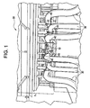
- Figure 1 illustrates a perspective view from an inlet side of a main steam tunnel 50.
- Figure 1 illustrates the plurality of main steam pipes 30 entering an inlet side of the main steam tunnel 50.
- Steam pipes 30 may be either main steam pipes carrying steam from the main steam outlet of the reactor pressure vessel to the turbine, and/or may include feed water piping which provides condensed reactor coolant (the steam is condensed at the turbine by a main condenser and is pumped by a feed water pump to the reactor vessel via feed water piping.)
- the main steam tunnel 50 may include an entrance or inlet side 5 and an outlet or exit side 10, for example.
- each steam pipe 30 and/or feed water pipe 30 may be supported by a plurality of pipe supports 40.
- the plurality of pipe supports 40 provide a pipe support structure, for example a Lungmen pipe support structure, throughout the main steam tunnel 50.
- the pipe supports 40 take up a substantial amount of space within the main steam tunnel 50. Particularly, a substantial number of pipe supports 40 are located at the tunnel exit 10. The location and number of these pipe supports 40 may cause at least a partial blockage of the main steam tunnel 50. In other words, the number of pipe supports 40 within the main steam tunnel 50 may be oriented over and around various pipes 30 at the tunnel exit 10 in order to support the pipes as they carry the steam out of the main steam tunnel 50 toward the turbine, for example. In a Lungmen pipe support structure, the pipes 30 do not bend until they are clear of the pipe supports 40.
- the partial blockage within the main steam tunnel 50 due to the number and locations of the pipe supports 40 may cause form (i.e. pressure) losses, as steam flows over the pipe supports 40 during a postulated pipe rupture accident. Further, the form losses may also lead to a reduced pressure in the steam flow.
- An exemplary embodiment of the present invention is an arrangement for improving steam flow of steam generated in a nuclear reactor, including a pipe support for supporting a pipe in a steam tunnel of the nuclear reactor, a diverter element operatively attached to the pipe support in a direction opposite of the steam flow, so as to divide steam flow over the pipe support, and a combiner element operatively attached to the pipe support in the direction of the steam flow, so as to combine the divided steam flow into a continuous steam flow.
- the arrangement may reduce pressure losses inside of a steam tunnel of the nuclear reactor.
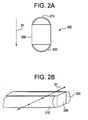
- Fig. 2A is a top view of an arrangement for improving steam flow in a nuclear reactor, in accordance with an exemplary embodiment of the present invention.
- Figure 2B is a perspective, exploded view illustrating the relationship of pipe halves to the pipe support in Figure 2A.
- Arrangement 200 may include a diverter element 210 and a combiner element 220 operatively attached or connected to a pipe support 230.
- the pipe support 230 may be one of a plurality of pipe supports in a pipe support structure supporting at least one of a plurality of main steam and/or feed water pipes in a steam tunnel of a boiling water reactor (BWR).
- Direction S1 may correspond to a direction of the steam flow in the steam tunnel.
- diverter element 210 is attached to the pipe support 230 so as to oppose the direction S1 of the steam flow.
- the combiner element 220 is attached to a side of the pipe support 230 in the direction S1 of the steam flow.
- the steam flow in the direction of S1 may thus be divided over diverter element 210 with reduced and/or minimal losses to steam flow pressure.
- part of the steam flow may flow over a first side of the pipe support 230 due to diverter element 210, and a remaining part of the steam flow may flow over a second side of the arrangement 200.
- the steam flow thus may pass over the pipe support 230 without incurring form (i.e. pressure) losses due to the pipe support, since the steam flow has been deflected slightly by diverter element 210, thus reducing turbulence and recirculation zones that may contribute to significant form losses.
- the divided steam flow may be combined by combiner element 220.
- combiner element 220 steam from along the first side and the second side of the arrangement 200 may be combined as a continuous steam flow.
- the diverter element 210 may be a portion of a pipe. As shown in Figs. 2A and 2B, the diverter element 210 is embodied as a half-pipe. However, it is understood that varying degrees of pipe may be used as the diverter element 210.
- the diverter element may be fabricated of steel or a steel alloy material, for example.
- the combiner element 220 may also be a portion of a pipe. As shown in Figs. 2A and 2B, the combiner element 220 is a half-pipe. However, it is understood that varying degrees of pipe may be used as the combiner element 220.
- the combiner element may also be fabricated of steel or a steel alloy material, for example.
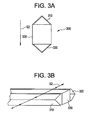
- Figs. 3A is a top view of an arrangement for improving steam flow in accordance with another exemplary embodiment.
- Fig. 3B is an exploded, perspective view showing diverter and combiner elements 310 and 320 in relation to pipe support 330.
- direction S2 may correspond to a direction of the steam flow in the steam tunnel.
- diverter element 310 is attached to a side of the pipe support 330 opposing the direction S2 of the steam flow
- the combiner element 320 is attached to a side of the pipe support 330 in the direction S2 of the steam flow.
- the steam flow in the direction of S2, may be divided over diverter element 310 with minimal losses to the pressure of the steam flow; namely, part of the steam flow may flow over a first side of the arrangement 300 and a remaining part of the steam flow may flow over a second side of the arrangement 300.
- the steam flow may pass over the pipe support 330 without incurring form losses by the pipe support.
- the diverter element 310 may be a portion of an angle iron made of steel or a steel alloy. As shown in Figs. 3A and 3B, the diverter element 310 is an angle iron including a right angle. However, it is understood that various angles in the angle iron may be used as the diverter element 310.
- the combiner element 320 may also be a portion of a steel or steel alloy angle iron including a right angle. However, it is understood that various angles in the angle iron may be used as the combiner element 320.
- diverter elements and combiner elements have been described as a portion of a pipe and/or a portion of an angle iron.
- any shape which may substantially divide a flow and then recombine a flow may be used.
- above-described embodiments of diverter elements and combiner elements have been described as being applied at a tunnel exit of a BWR.
- the diverter elements and combiner elements may be applied to any of the plurality of pipe supports in the steam tunnel.
- the angle iron in the diverter element and/or the combiner element may be fabricated from at least two flat plates. For example, two flat plates may be welded together, thus forming the angle iron.
- pipe support structure has been discussed above in terms of a generic pipe support structure.
- exemplary embodiments of the present invention may be employed in any pipe support structure, for example a Lungmen pipe support structure.
Landscapes
- Physics & Mathematics (AREA)
- Engineering & Computer Science (AREA)
- Plasma & Fusion (AREA)
- General Engineering & Computer Science (AREA)
- High Energy & Nuclear Physics (AREA)
- Structure Of Emergency Protection For Nuclear Reactors (AREA)
Abstract

Description
- The present invention relates generally to an apparatus for mitigating pressure loss in a steam tunnel of a boiling water reactor (BWR), and to a method of mitigating pressure loss in a steam tunnel of the BWR.
- A boiling water reactor (BWR) is a reactor in which water, used as both coolant and moderator, is allowed to boil in the reactor vessel. The resulting steam may be used directly to drive a turbine, which may in turn drive an electrical generator, for example through direct coupling, thereby producing electricity. In a typical BWR, the reactor core creates heat and a single loop both delivers steam to the turbine and returns water to the reactor core to cool it. The cooling water (i.e. working fluid) may be circulated by electrically powered and/or steam-driven pumps.
- A BWR typically includes a reactor pressure vessel, which houses the reactor core, and associated control blades, which control the fission reaction therein. The reactor pressure vessel is typically positioned within a containment or drywell of a reactor containment building, such as a reactor plant site, for example. Thus, a BWR boils the reactor coolant to convert the coolant into steam. The steam exits at an upper portion of the reactor vessel such as at a main steam outlet nozzle, and may travel through a series of steam pipes within a main steam tunnel adjacent to the containment building. The main steam tunnel provides a pathway for the main steam piping from the reactor pressure vessel to an inlet of the turbine, which would utilize the steam in order to generate electricity.
- Figure 1 illustrates a perspective view from an inlet side of a
main steam tunnel 50. Figure 1 illustrates the plurality ofmain steam pipes 30 entering an inlet side of themain steam tunnel 50.Steam pipes 30 may be either main steam pipes carrying steam from the main steam outlet of the reactor pressure vessel to the turbine, and/or may include feed water piping which provides condensed reactor coolant (the steam is condensed at the turbine by a main condenser and is pumped by a feed water pump to the reactor vessel via feed water piping.) - Referring now to Figure 1, the
main steam tunnel 50 may include an entrance orinlet side 5 and an outlet orexit side 10, for example. Within themain steam tunnel 50, eachsteam pipe 30 and/orfeed water pipe 30 may be supported by a plurality of pipe supports 40. The plurality of pipe supports 40 provide a pipe support structure, for example a Lungmen pipe support structure, throughout themain steam tunnel 50. - The pipe supports 40 take up a substantial amount of space within the
main steam tunnel 50. Particularly, a substantial number ofpipe supports 40 are located at thetunnel exit 10. The location and number of these pipe supports 40 may cause at least a partial blockage of themain steam tunnel 50. In other words, the number of pipe supports 40 within themain steam tunnel 50 may be oriented over and aroundvarious pipes 30 at thetunnel exit 10 in order to support the pipes as they carry the steam out of themain steam tunnel 50 toward the turbine, for example. In a Lungmen pipe support structure, thepipes 30 do not bend until they are clear of the pipe supports 40. - Thus, the partial blockage within the
main steam tunnel 50 due to the number and locations of the pipe supports 40 may cause form (i.e. pressure) losses, as steam flows over the pipe supports 40 during a postulated pipe rupture accident. Further, the form losses may also lead to a reduced pressure in the steam flow. - An exemplary embodiment of the present invention is an arrangement for improving steam flow of steam generated in a nuclear reactor, including a pipe support for supporting a pipe in a steam tunnel of the nuclear reactor, a diverter element operatively attached to the pipe support in a direction opposite of the steam flow, so as to divide steam flow over the pipe support, and a combiner element operatively attached to the pipe support in the direction of the steam flow, so as to combine the divided steam flow into a continuous steam flow. The arrangement may reduce pressure losses inside of a steam tunnel of the nuclear reactor.
- The invention will now be described in greater detail, by way of example, with reference to the drawings, in which:-
- Fig. 1 illustrates a steam tunnel with pipe supports according to conventional methods.
- Fig. 2A is a top view of an arrangement for improving steam flow in a nuclear reactor, in accordance with an exemplary embodiment of the present invention.
- Figure 2B is a perspective, exploded view illustrating the relationship of pipe halves to the pipe support in figure 2A.
- Fig. 3A is a top view of another arrangement for improving steam flow in a nuclear reactor, in accordance with an exemplary embodiment of the present invention.
- Figure 3B is a perspective, exploded view illustrating the relationship of angle irons to the pipe support in Figure 3A.
- Fig. 2A is a top view of an arrangement for improving steam flow in a nuclear reactor, in accordance with an exemplary embodiment of the present invention. Figure 2B is a perspective, exploded view illustrating the relationship of pipe halves to the pipe support in Figure 2A.
Arrangement 200 may include adiverter element 210 and acombiner element 220 operatively attached or connected to apipe support 230. Thepipe support 230 may be one of a plurality of pipe supports in a pipe support structure supporting at least one of a plurality of main steam and/or feed water pipes in a steam tunnel of a boiling water reactor (BWR). Direction S1 may correspond to a direction of the steam flow in the steam tunnel. As shown,diverter element 210 is attached to thepipe support 230 so as to oppose the direction S1 of the steam flow. Thecombiner element 220 is attached to a side of thepipe support 230 in the direction S1 of the steam flow. - The steam flow in the direction of S1 may thus be divided over
diverter element 210 with reduced and/or minimal losses to steam flow pressure. For example, part of the steam flow may flow over a first side of thepipe support 230 due todiverter element 210, and a remaining part of the steam flow may flow over a second side of thearrangement 200. The steam flow thus may pass over thepipe support 230 without incurring form (i.e. pressure) losses due to the pipe support, since the steam flow has been deflected slightly bydiverter element 210, thus reducing turbulence and recirculation zones that may contribute to significant form losses. - The divided steam flow may be combined by combiner
element 220. At thecombiner element 220, steam from along the first side and the second side of thearrangement 200 may be combined as a continuous steam flow. - The
diverter element 210 may be a portion of a pipe. As shown in Figs. 2A and 2B, thediverter element 210 is embodied as a half-pipe. However, it is understood that varying degrees of pipe may be used as thediverter element 210. The diverter element may be fabricated of steel or a steel alloy material, for example. - The
combiner element 220 may also be a portion of a pipe. As shown in Figs. 2A and 2B, thecombiner element 220 is a half-pipe. However, it is understood that varying degrees of pipe may be used as thecombiner element 220. The combiner element may also be fabricated of steel or a steel alloy material, for example. - Figs. 3A is a top view of an arrangement for improving steam flow in accordance with another exemplary embodiment. Fig. 3B is an exploded, perspective view showing diverter and combiner
elements pipe support 330. - Referring to Figs. 3A and 3B, direction S2 may correspond to a direction of the steam flow in the steam tunnel. As shown,
diverter element 310 is attached to a side of thepipe support 330 opposing the direction S2 of the steam flow, and thecombiner element 320 is attached to a side of thepipe support 330 in the direction S2 of the steam flow. - The steam flow, in the direction of S2, may be divided over
diverter element 310 with minimal losses to the pressure of the steam flow; namely, part of the steam flow may flow over a first side of thearrangement 300 and a remaining part of the steam flow may flow over a second side of thearrangement 300. After being divided overdiverter element 310, the steam flow may pass over thepipe support 330 without incurring form losses by the pipe support. - The
diverter element 310 may be a portion of an angle iron made of steel or a steel alloy. As shown in Figs. 3A and 3B, thediverter element 310 is an angle iron including a right angle. However, it is understood that various angles in the angle iron may be used as thediverter element 310. Thecombiner element 320 may also be a portion of a steel or steel alloy angle iron including a right angle. However, it is understood that various angles in the angle iron may be used as thecombiner element 320. - The exemplary embodiments of the present invention being thus described, it will be obvious that the same may be varied in many ways. For example, above-described embodiments of diverter elements and combiner elements have been described as a portion of a pipe and/or a portion of an angle iron. However, any shape which may substantially divide a flow and then recombine a flow may be used. Further, above-described embodiments of diverter elements and combiner elements have been described as being applied at a tunnel exit of a BWR. However, the diverter elements and combiner elements may be applied to any of the plurality of pipe supports in the steam tunnel. Further, for example, the angle iron in the diverter element and/or the combiner element may be fabricated from at least two flat plates. For example, two flat plates may be welded together, thus forming the angle iron.
- Further, the pipe support structure has been discussed above in terms of a generic pipe support structure. However, it is understood that the exemplary embodiments of the present invention may be employed in any pipe support structure, for example a Lungmen pipe support structure.
Claims (10)
- An arrangement (200, 300) for improving steam flow of steam generated in a nuclear reactor, comprising:a pipe support (230, 330) for supporting a pipe in a steam tunnel (50) of the nuclear reactor;a diverter element (210, 310) operatively attached to the pipe support (230, 330) in a direction opposite of the steam flow, so as to divide steam flow over the pipe support (230, 330); anda combiner element (220, 320) operatively attached to the pipe support (230, 330) in the direction of the steam flow, so as to combine the divided steam flow into a continuous steam flow.
- The arrangement (200, 300) of claim 1, wherein the diverter element (210, 310) is a portion of a pipe attached to a surface of the pipe support (230, 330).
- The arrangement (200, 300) of claim 1 or 2, wherein the combiner element (220, 320) is a portion of a pipe attached to a surface of the pipe support (230, 330).
- The arrangement (200, 300) of claim 1, wherein the diverter element (210, 310) is an angle iron attached to a surface of the pipe support (230, 330).
- The arrangement (200, 300) of claim 1, wherein the combiner element (220, 320) is an angle iron attached to a surface of the pipe support (230, 330).
- The arrangement (200, 300) of claim 1, wherein the pipe support (230, 330) is a portion of a Lungmen pipe support structure.
- The arrangement (200, 300) of claim 4, wherein the angle iron includes at least two flat plates.
- The arrangement (200, 300) of claim 7, wherein the at least two flat plates are welded together.
- The arrangement (200, 300) of claim 5, wherein the angle iron includes at least two flat plates.
- The arrangement (200, 300) of claim 9, wherein the at least two flat plates are welded together.
Applications Claiming Priority (1)
| Application Number | Priority Date | Filing Date | Title |
|---|---|---|---|
| US10/929,489 US20060045230A1 (en) | 2004-08-31 | 2004-08-31 | Method and apparatus for mitigating pressure loss in a steam tunnel of a boiling water reactor |
Publications (1)
| Publication Number | Publication Date |
|---|---|
| EP1630822A1 true EP1630822A1 (en) | 2006-03-01 |
Family
ID=35463779
Family Applications (1)
| Application Number | Title | Priority Date | Filing Date |
|---|---|---|---|
| EP05254711A Withdrawn EP1630822A1 (en) | 2004-08-31 | 2005-07-28 | Arrangement for mitigating pressure loss in a steam tunnel of a boiling water reactor |
Country Status (4)
| Country | Link |
|---|---|
| US (1) | US20060045230A1 (en) |
| EP (1) | EP1630822A1 (en) |
| JP (1) | JP2006071637A (en) |
| TW (1) | TW200620324A (en) |
Citations (5)
| Publication number | Priority date | Publication date | Assignee | Title |
|---|---|---|---|---|
| JPS57144489A (en) * | 1981-03-04 | 1982-09-07 | Hitachi Ltd | Pressure suppression device of nuclear reactor container |
| JPS58184488A (en) * | 1982-04-21 | 1983-10-27 | Mitsubishi Heavy Ind Ltd | Condenser |
| JPS63127089A (en) * | 1986-11-14 | 1988-05-30 | Hitachi Ltd | Thermal conducting pipe supporting structure |
| JPH01150798A (en) * | 1987-12-08 | 1989-06-13 | Hitachi Ltd | Heat transfer pipe support structure |
| JPH05164877A (en) * | 1991-12-17 | 1993-06-29 | Hitachi Ltd | Boiling water reactor |
Family Cites Families (5)
| Publication number | Priority date | Publication date | Assignee | Title |
|---|---|---|---|---|
| US3865688A (en) * | 1970-08-05 | 1975-02-11 | Frank W Kleimola | Passive containment system |
| US4644780A (en) * | 1983-10-19 | 1987-02-24 | Westinghouse Electric Corp. | Self-supporting pipe rupture and whip restraint |
| JPS61129596A (en) * | 1984-09-25 | 1986-06-17 | 株式会社日立製作所 | Main steam pipe tunnel room with horizontal radiation monitor |
| JPS6475993A (en) * | 1987-09-18 | 1989-03-22 | Toshiba Corp | Setting of embedded metal fixtures |
| JPH0216495A (en) * | 1988-07-04 | 1990-01-19 | Toshiba Corp | Blow-out device |
-
2004
- 2004-08-31 US US10/929,489 patent/US20060045230A1/en not_active Abandoned
-
2005
- 2005-07-28 EP EP05254711A patent/EP1630822A1/en not_active Withdrawn
- 2005-08-18 TW TW094128237A patent/TW200620324A/en unknown
- 2005-08-30 JP JP2005248564A patent/JP2006071637A/en active Pending
Patent Citations (5)
| Publication number | Priority date | Publication date | Assignee | Title |
|---|---|---|---|---|
| JPS57144489A (en) * | 1981-03-04 | 1982-09-07 | Hitachi Ltd | Pressure suppression device of nuclear reactor container |
| JPS58184488A (en) * | 1982-04-21 | 1983-10-27 | Mitsubishi Heavy Ind Ltd | Condenser |
| JPS63127089A (en) * | 1986-11-14 | 1988-05-30 | Hitachi Ltd | Thermal conducting pipe supporting structure |
| JPH01150798A (en) * | 1987-12-08 | 1989-06-13 | Hitachi Ltd | Heat transfer pipe support structure |
| JPH05164877A (en) * | 1991-12-17 | 1993-06-29 | Hitachi Ltd | Boiling water reactor |
Non-Patent Citations (5)
| Title |
|---|
| DATABASE WPI Section Ch Week 198918, Derwent World Patents Index; Class K06, AN 1989-136338, XP002360665 * |
| PATENT ABSTRACTS OF JAPAN vol. 008, no. 026 (M - 273) 3 February 1984 (1984-02-03) * |
| PATENT ABSTRACTS OF JAPAN vol. 012, no. 376 (M - 750) 7 October 1988 (1988-10-07) * |
| PATENT ABSTRACTS OF JAPAN vol. 013, no. 411 (M - 869) 11 September 1989 (1989-09-11) * |
| PATENT ABSTRACTS OF JAPAN vol. 017, no. 566 (P - 1629) 14 October 1993 (1993-10-14) * |
Also Published As
| Publication number | Publication date |
|---|---|
| US20060045230A1 (en) | 2006-03-02 |
| TW200620324A (en) | 2006-06-16 |
| JP2006071637A (en) | 2006-03-16 |
Similar Documents
| Publication | Publication Date | Title |
|---|---|---|
| US11145424B2 (en) | Direct heat exchanger for molten chloride fast reactor | |
| US8971477B2 (en) | Integral helical coil pressurized water nuclear reactor | |
| JP5542062B2 (en) | Neutron shielding panels for reactor pressure vessels. | |
| US8908822B2 (en) | Nuclear reactor | |
| KR20130118862A (en) | Compact nuclear reactor with integral steam generator | |
| EP2165339A1 (en) | Nuclear reactor downcomer flow deflector | |
| KR20110105375A (en) | Reactor Vessel Reflector with Integrated Flow Pass | |
| JP6791511B2 (en) | Reactor | |
| EP1630822A1 (en) | Arrangement for mitigating pressure loss in a steam tunnel of a boiling water reactor | |
| CA2352914C (en) | Supercritical water cooled reactor and power generation plant | |
| Duffey et al. | SCW pressure-channel nuclear reactors: some design features and concepts | |
| JP7416544B2 (en) | Molten salt fast reactor | |
| US4296713A (en) | Vapor generator | |
| Oriani et al. | Thermal hydraulic tradeoffs in the design of IRIS primary circuit | |
| KR102884047B1 (en) | Heat Exchanger and Reactor including the same | |
| US12512230B2 (en) | Passively-cooled spent nuclear fuel pool system | |
| KR100647808B1 (en) | Integral Reactor Flow Mixing Header | |
| RU2776940C2 (en) | Pool type liquid-metal fast neutron reactor using connection of plate heat exchanger with etched channels and power conversion system | |
| EP3324007A1 (en) | Moisture separation unit and vapor turbine plant | |
| Joo et al. | Concept Development of Boiling Condensing Small Modular Reactor (BCR) | |
| KR100900730B1 (en) | Steam generator cassette structure for flow mixing of integral reactor | |
| RU2355054C1 (en) | Emergency cooler of nuclear reactor | |
| Cinotti | The inherently safe immersed system (ISIS): Safety and economic aspects | |
| JP2942330B2 (en) | Boiling water reactor | |
| Cinotti | ISIS, safety and economic aspects in view of co-generation of heat and electricity |
Legal Events
| Date | Code | Title | Description |
|---|---|---|---|
| PUAI | Public reference made under article 153(3) epc to a published international application that has entered the european phase |
Free format text: ORIGINAL CODE: 0009012 |
|
| AK | Designated contracting states |
Kind code of ref document: A1 Designated state(s): AT BE BG CH CY CZ DE DK EE ES FI FR GB GR HU IE IS IT LI LT LU LV MC NL PL PT RO SE SI SK TR |
|
| AX | Request for extension of the european patent |
Extension state: AL BA HR MK YU |
|
| 17P | Request for examination filed |
Effective date: 20060901 |
|
| AKX | Designation fees paid |
Designated state(s): DE ES FI SE |
|
| R17C | First examination report despatched (corrected) |
Effective date: 20061010 |
|
| GRAP | Despatch of communication of intention to grant a patent |
Free format text: ORIGINAL CODE: EPIDOSNIGR1 |
|
| STAA | Information on the status of an ep patent application or granted ep patent |
Free format text: STATUS: THE APPLICATION IS DEEMED TO BE WITHDRAWN |
|
| 18D | Application deemed to be withdrawn |
Effective date: 20100615 |