EP1630293A1 - Rotationseinheit für Brücken - Google Patents
Rotationseinheit für Brücken Download PDFInfo
- Publication number
- EP1630293A1 EP1630293A1 EP05447191A EP05447191A EP1630293A1 EP 1630293 A1 EP1630293 A1 EP 1630293A1 EP 05447191 A EP05447191 A EP 05447191A EP 05447191 A EP05447191 A EP 05447191A EP 1630293 A1 EP1630293 A1 EP 1630293A1
- Authority
- EP
- European Patent Office
- Prior art keywords
- bridge
- rotary unit
- rotating
- section
- lifting means
- Prior art date
- Legal status (The legal status is an assumption and is not a legal conclusion. Google has not performed a legal analysis and makes no representation as to the accuracy of the status listed.)
- Granted
Links
Images


Classifications
-
- E—FIXED CONSTRUCTIONS
- E01—CONSTRUCTION OF ROADS, RAILWAYS, OR BRIDGES
- E01D—CONSTRUCTION OF BRIDGES, ELEVATED ROADWAYS OR VIADUCTS; ASSEMBLY OF BRIDGES
- E01D15/00—Movable or portable bridges; Floating bridges
- E01D15/04—Swing bridges
Definitions
- the present invention relates to moveable horizontal constructions. More particularly, the present invention relates to a rotary unit for a moveable horizontal construction such as e.g. a bridge like a swing bridge, to a construction, e.g. bridge, using such a rotary unit and to a method for operating such a moveable horizontal construction, such as e.g. a swing bridge.
- a rotary unit for a moveable horizontal construction such as e.g. a bridge like a swing bridge
- a construction e.g. bridge
- a method for operating such a moveable horizontal construction such as e.g. a swing bridge.
- a swing type bridge typically one bridge section is turned in a horizontal plane around a vertical pivot and when closed, its ends are supported at the proper level.
- the pivot can be positioned either in the centre of the rotatable bridge section, thus making typically two openings for water traffic, or it may be positioned rather at one side of the centre, thus making one larger opening for water traffic and one smaller opening for water traffic. In the latter case, typically a counterweight is used to balance the bridge about its pivot.
- two pivots are used and two bridge sections are rotated, typically such that, in closed position the sections meet in the centre of the waterway to be spanned.
- a locking arrangement then is needed to lock the bridge sections together in the centre and to lock the other ends of the bridge sections to the shores.
- swing type bridges typically need a lifting arrangement to lift the end of the bridge section or bridge sections near the shore so that the bridge sections make a continuous span with the surface on the shore, i.e. typically the road or railway.
- the end parts typically are lifted and Supporting means such as e.g. pins are introduced between the shore and the end parts of the bridge section(s).
- the lifting typically is done based on rollers, screws, cams, eccentrics, toggle joints, etc. Lifting the bridge from the centre typically is less preferred as it requires a larger power consumption.
- Known swing type bridges with a lifting arrangement in the centre furthermore have the disadvantage that a part of the truss, that carries the stress while swinging, is taken by the lifting means, thereby limiting the available top side of the carrying surface.
- the supporting means are pulled back or shifted away, whereby the end points of the bridge-sections are typically slightly lower in vertical position, due to the weight of the bridge sections.
- swing bridges are used as railway bridges or bridges to at least partly transfer vehicles running on tracks, which is often the case as swing bridges are best adapted for long and heavy spans, the issue of obtaining good connection between the tracks on the shore and the tracks on the bridge is very important.
- a small spacing between the tracks on the shore and the tracks on the bridge-section(s) is present, in this way reducing the comfort and safety of the track-based vehicles.
- the tracks typically are interrupted between the bridge sections and the shore making a gap oriented transverse the direction of the tracks, which increases the lack of comfort and safety.
- Another important issue for bridge construction is reliability of operation of the system. If a bridge fails, either the water traffic or the road traffic, e.g. railroad traffic, is blocked, which can lead to a significant economical cost, both in time and in money.
- the invention relates to a rotary unit for rotating a substantially horizontal construction, the rotary unit comprising a plurality of lifting means coupled to a means for rotating, whereby said plurality of lifting means are adapted for vertically moving said horizontal construction and said means for rotating is adapted for horizontally rotating said horizontal construction.
- the horizontal construction may be a bridge such as e.g. a swing bridge.
- the plurality of lifting means may be a plurality of hydraulic cylinders.
- the coupling of the plurality of lifting means to the means for rotating may be obtained by swivel joints.
- the means for rotating may have at least a bottom portion.
- the plurality of lifting means may be adapted for supporting said means for rotating substantially homogeneous over said bottom portion.
- Substantially homogeneous may mean that the lifting means may be positioned in a circular arrangement under the ring bearings or close to the ring bearings.
- the rotary unit may furthermore comprise a base, wherein said plurality of lifting means may be coupled to the base using swivel joints.
- the means for rotating may comprise an outer ring bearing, an inner ring bearing and at least one gear unit, whereby one of said inner ring bearing or outer ring bearing is connected to the substantially horizontal construction and is adapted to be driven by the at least one gear unit.
- the at least one gear unit may be a planar gear unit.
- the at least one gear unit may be a plurality of gear units.
- the plurality of lifting means may comprise preferably at least 2, more preferably at least 4, even more preferably at least 6, still more preferably at least 8 hydraulic cylinders.
- the rotary unit may furthermore comprise an additional guiding system for guiding said vertically movement.
- the additional guiding system may be based on vertical steel bars and wheels running on said vertical steel bars.
- the invention also relates to a rotatable bridge construction, the bridge construction comprising a substantially horizontal bridge-section and a rotary unit, the rotary unit comprising a plurality of lifting means and a means for rotating, wherein said plurality of lifting means are adapted for vertically moving said substantially horizontal bridge-section and said means for rotating is adapted for rotating said substantially horizontal bridge-section horizontally.
- the invention also relates to a rotatable horizontal construction, the horizontal construction comprising a horizontal section and a rotary unit, the rotary unit comprising a plurality of lifting means and a means for rotating, wherein said plurality of lifting means are adapted for vertically moving said substantially horizontal section and said means for rotating is adapted for rotating said substantially horizontal section horizontally, i.e. in a horizontal plane.
- the invention furthermore relates to a method for rotating a horizontal construction-section of a rotatable horizontal construction, the method comprising moving said horizontal construction-section in a vertical direction using at least two of a plurality of lifting means and rotating said horizontal construction-section horizontally using a means for rotating.
- the moving may be lifting or may be lowering the horizontal construction-section.
- the rotary unit comprises a plurality of lifting means, whereby upon failure of one or more lifting means the system's operation still may be guaranteed.
- the track interruption between the bridge-section and the shore side can be made different from transverse to the track direction, which diminishes the shock or impact on the track-based vehicle when crossing the interruption.
- teachings of the present invention permit the design of improved methods and apparatus for units for swing bridges and the swing bridges using these units, especially - but not limited to - swing bridges used at least partly as railway bridge.
- a device A coupled to a device B should not be limited to devices or systems wherein an output of device A is directly connected to an input of device B. It means that there exists a path between an output of A and an input of B which may be a path including other devices or means.
- the present invention relates to a system for use in a rotatable horizontal construction, such as a bridge, e.g. a swing bridge.
- a rotatable horizontal construction such as a bridge, e.g. a swing bridge.
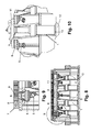
- the rotary unit 10 or parts thereof is shown in Fig. 1 to Fig. 5 for the situation whereby the rotatable horizontal construction, such as e.g. a bridge, is closed and in Fig. 6 to Fig. 10 for a rotatable bridge construction that is lifted, i.e. for example if a bridge moved by the rotary unit 10 is open such that water traffic can pass.
- the system consists of a rotary unit 10 comprising a plurality of lifting means 1 and a means for rotating 14 a section of a horizontal construction, e.g. a bridge section.
- the plurality of lifting means 1 typically are hydraulic lifting means such as e.g. hydraulic cylinders, although other lifting means which are suitable for lifting a horizontal construction, such as e.g. a bridge section also can be used.
- the number of lifting means 1 and the size thereof typically depends on the horizontal construction that is to be lifted, the length of the section, the width of the section and the used materials for the construction.
- the number of lifting means 1 is significantly high such that if one or possibly more of the lifting means 1 is not-operational anymore, sufficiently other operational lifting means 1 are available such that the horizontal construction, e.g. bridge, still can be operated. Redundancy may thus be provided.
- the system preferably has 2 or more lifting means, more preferably 4 or more lifting means, even more preferably 8 or more lifting means. Therefore, preferably the lifting means 1 are distributed over the means for rotating 14, e.g. over the bottom side thereof, which is in the present example supported by the lifting means 1. In this way, even upon failure and/or removal of a lifting means 1 the other lifting means 1 still can keep the horizontal construction such as e.g. the bridge-section in balance.
- the plurality of lifting means 1 are connected to the means for rotating 14 by means of a joint construction 3, as illustrated e.g. in Fig. 5 and Fig. 10.
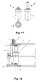
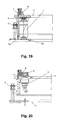
- Fig. 17 to Fig. 19 further illustrate by way of example a possible implementation of a lifting means 1 of the rotary unit 10.
- Fig. 17 shows a hydraulic cylinder as one of the lifting means 1, both in non-lifted position (S) and in lifted position (S') in side view, and in top view (T).
- Fig. 18 and Fig. 19 show one of the lifting means embedded in the rotary unit 10 in lifted position and in non-lifted position, respectively.
- the joint constructions 3 are also shown.
- these joint constructions 3 are swivel joint constructions such that they allow a certain misalignment for the horizontal construction such as e.g. the bridge-section, thereby preventing too large side forces acting on the plurality of lifting means 1, such as e.g. the hydraulic cylinders.
- the means for rotating 14 can be any means for rotating a horizontal construction such as e.g. a bridge-section, such as e.g. - but not limited to - a stack of discs, conical rollers or balls on a track and ring bearing, etc.
- the means for rotating 14 comprises a bottom portion 11, which is connected to the plurality of lifting means 1, a large inner ring bearing 8 and an outer ring bearing 7.
- One of these ring bearings 7, 8 is connected to the horizontal construction, e.g. the bridge section that is to be rotated horizontally, whereas the other one is fixed to the bottom portion 11 of the means for rotating 14.
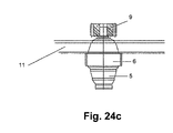
- Gear units 9, for gearing the ring bearing 8 can be driven in any suitable way, such as by e.g. hydraulical or electrical motors 5. Examples of ring bearings are shown in more detail in Fig. 21 a to Fig. 24b.
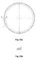
- Fig. 21 a and Fig. 21 b illustrate the combination of an outer ring bearing 7 and an inner ring bearing 8.
- Fig. 21 a shows a top view
- Fig. 21 b shows a cross section along line D-D'.
- Fig. 22a and Fig. 23a illustrate the inner ring bearing 8 respectively the outer ring bearing 7, whereas Fig. 22b and Fig.
- FIG. 23b illustrate cross sections along lines E-E' and F-F'.
- Fig. 24a and Fig. 24b illustrate the ring bearings 7, 8 and their relative position with respect to each other and to the surrounding components.
- Fig. 20 and Fig. 24c are illustrations of a driving gear 9 for creating rotation of the horizontal construction and the position and coupling of such a driving gear 9 to the surrounding parts of the rotary unit 10.
- the inner ring bearing 8 is shown to be driven by gear planar units 9, although other types of reduction gear units 9 also can be used. Transfer of the power generated by the motor 5 to the gear planar units 9 is in this example done indirectly via an intermediate planar unit 6 whereon the gear planar units 9 are mounted and which are driven by the motor 5.
- a number of Brevini EC4250 gear units may be used.
- the inner ring bearing 8 is fixedly connected to the horizontal construction, e.g. bridge section, as can be appreciated from Fig. 18 to 20, such that rotation of the inner ring bearing 8 will lead to rotation of the horizontal construction, e.g. the bridge section.
- the outer ring bearing 7 is connected to the remaining portion of the means for rotating 14, it is e.g. the bottom portion 11 of the means for rotating 14.
- the number of gear units 9 and the number of motors 5 preferably is larger than one, thus providing redundancy, such that upon failure of one of the elements, the system can further be operated.
- the base 12 typically will be connected to a pile, which is positioned under the horizontal construction, e.g. bridge section, such that the pile supports the rotary unit 10 and thus indirectly the horizontal construction, e.g. bridge section.
- the lifting means 1 could be immediately connected to the environment, i.e. for example to the pile supporting the structure.
- An advantage of the use of a base 12 is that support for the vertical movement can be provided by e.g. wheels 2 that are supported by the base 12 and run on vertical steel bars 4 mounted on the vertically moveable assembly of the construction, i.e. on the means for rotating 14, or vice versa.
- the preferred materials from which the rotary unit is built can be any material that has the strength to support a horizontal construction.
- the material choice may also be influenced from environmental circumstances.
- a typical material, although the invention is not limited thereto, that can be used is steel.
- the size of the components of the rotary unit 10 depends on the size and weight of the horizontal construction and can be easily calculated by a person skilled in the art.
- the invention also relates to a horizontal construction such as e.g. a swing bridge using the rotary unit 10 as described in the first embodiment.
- the swing bridge using the rotary unit 10 can be any type of swing bridge, e.g. in a centrally supported swing bridge-section whereby a double pathway is cleared for the water traffic or in an asymmetrically supported swing bridge whereby the rotary unit is positioned at one side of the centre of the bridge-section.
- the shortest arm of the bridge-section typically is provided with a counter weight to allow the bridge-section to be balanced around the rotary unit 10, as well known by a person skilled in the art.
- the invention is especially useful for railway bridges, i.e.
- any bridge that at least partly provides a throughway to track-based vehicle traffic as it allows to provide an improved transition between the tracks on the shore and the tracks on the bridge section.
- the bridge may have non-moveable sections, which in the present application will play the same role as the shore edges.
- the bridges are also especially useful on places where there is a lot of bridge operation, as it has a high degree of reliability for operation.
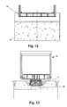
- a swing bridge 50 with a centrally supported swing bridge section 52 is illustrated in Fig. 11 to Fig. 15, the invention not being limited thereto.
- Fig. 11 a side view is shown of the swing bridge 50 in a position allowing traffic from one shore to the other.
- FIG. 14 are cross-sectional views of the bridge 50 and its environment along lines AA', BB' and CC'.
- the bridge section 52 is shown, in combination with part of the first shore 54.
- the bridge section 52 is shown in combination with the rotary unit 10 and the pile 56 supporting the rotary unit 10 and thus indirectly the bridge section 52.
- the bridge section 52 is shown in combination with part of the second shore 58.
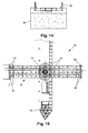
- a top view of the swing bridge 50 is shown, furthermore indicating a means for centering 60 the bridge 50 in an open position, i.e. for allowing traffic along the waterway or obstacle bridged by the swing bridge section 52, and buffering means 62 for buffering the swing bridge section 52 during rotating.
- FIG. 16 shows a cross-sectional top view of a rotary unit 10 according to the previous embodiment, as can be used in the horizontal swing construction according to the present embodiment. Besides the parts as shown in drawings Fig. 1 to Fig.10 and Fig. 17 to Fig. 24c, Fig. 16 also illustrates the possibility for using a base portion 20 which is rotatable and which is connected to the horizontal construction on the one hand and, in the present example, to the rotatable inner bearing 8 on the other hand.
- the present invention relates to a method for operating a horizontal construction such as e.g. a swing bridge using any of a rotary unit 10 as described above.
- a horizontal construction such as e.g. a swing bridge using any of a rotary unit 10 as described above.
- the method will be described with reference to a bridge.
- the bridge 50 is first unlocked so that it is given free for mechanical movement. Typically locking is done by a set of pins or a system of locks. After unlocking is done, the plurality of lifting means 1, i.e. e.g. the hydraulic cylinders, push the bridge-section 52 up to a certain position which is needed for turning the bridge 50.
- the distance over which the horizontally oriented bridge 50 is pushed up or down in the vertical direction typically is of the order of a few tens of centimetres, such as e.g. over 50cm. Supporting wheels 2 running in vertically steel bars 4 may provide additional support for this vertical movement. After this vertical movement, the rotary unit 10 is in a state as shown by way of example in Fig. 6 to Fig. 10.
- the bridge 50 is ready for turning.
- the rotational movement in the horizontal plane defined by the horizontal orientation of the bridge-section 52 or in other words the swing is done by driving the gear units 9 such that the geared ring bearing 8 rotates and the bridge-section, connected to this section also rotates.
- the inversion action is performed, i.e. the bridge 50 is rotated back in between the two shores and after this rotational movement, the bridge-section 52 is lowered.
- the bridge-section is first brought to another vertical height, preferably above the vertical height of the edge of the shore.
- parts can be mounted on the bridge section that extend over the edge of the bridge section. If e.g. railway tracks are placed on the bridge section, these can at least extend partly over the bridge section such that they allow to make a smooth transition to railway tracks on the shore.
- This furthermore allows to reduce the interruption in the railway tracks and to change the direction of the interruption from transverse to the railway track direction to diagonal, i.e. slightly in the length direction of the railway track. This results in a more smooth transition between the railway track parts.
- the invention also relates to a method for closing the swing bridge.
- the method then comprises first rotating the horizontal construction-section of the swing bridge substantially in a horizontal plane and then lowering or raising the horizontal construction-section substantially vertically.
- the method for rotating a horizontal construction-section of a rotatable horizontal construction comprises the steps of lifting the horizontal construction-section and rotating the lifted horizontal construction-section
- the method also could comprise lowering a horizontal construction-section and then rotating it.
- the system according to the present invention then should have lifting means, which in this case also could be referred to as lowering means, that are in a lifted state when the bridge can be used for allowing traffic from one shore to the other.
- the shore needs to be adapted such that it provides sufficient space for iowering the horizontal construction-section and for rotating the horizontal construction-section.
- the horizontal construction is a bridge comprising tracks
- the interruption between the tracks still may be slightly along the length direction of the tracks if the interruption is provided on the horizontal construction-section instead of at the shores.
Landscapes
- Engineering & Computer Science (AREA)
- Architecture (AREA)
- Civil Engineering (AREA)
- Structural Engineering (AREA)
- Bridges Or Land Bridges (AREA)
Applications Claiming Priority (1)
| Application Number | Priority Date | Filing Date | Title |
|---|---|---|---|
| GB0418951A GB0418951D0 (en) | 2004-08-25 | 2004-08-25 | Rotary unit for bridges |
Publications (2)
| Publication Number | Publication Date |
|---|---|
| EP1630293A1 true EP1630293A1 (de) | 2006-03-01 |
| EP1630293B1 EP1630293B1 (de) | 2016-03-16 |
Family
ID=33104616
Family Applications (1)
| Application Number | Title | Priority Date | Filing Date |
|---|---|---|---|
| EP05447191.7A Expired - Lifetime EP1630293B1 (de) | 2004-08-25 | 2005-08-25 | Rotierbare Brückenkonstruktion |
Country Status (2)
| Country | Link |
|---|---|
| EP (1) | EP1630293B1 (de) |
| GB (1) | GB0418951D0 (de) |
Cited By (1)
| Publication number | Priority date | Publication date | Assignee | Title |
|---|---|---|---|---|
| DE102022001746A1 (de) | 2022-05-18 | 2023-11-23 | Andreas Müller | Eine Bahnbrücke auf einem Brückenpfeiler, ein Walzendrehgleitkranz, ein Zahnrad-Motorantrieb, der die Bahnbrücke um 90-Grad dreht, eines Wasserschiffahrtkanales. |
Citations (3)
| Publication number | Priority date | Publication date | Assignee | Title |
|---|---|---|---|---|
| GB470982A (en) * | 1936-02-28 | 1937-08-26 | Reginald Alfred Charles Brie | Improvements in and relating to means for landing and launching aircraft |
| DE1163882B (de) * | 1961-07-05 | 1964-02-27 | Gutehoffnungshuette Sterkrade | Schwenkvorrichtung fuer Hubdrehbruecken |
| US4036377A (en) * | 1974-04-05 | 1977-07-19 | Fried. Krupp Gesellschaft Mit Beschrankter Haftung | Device for transporting loads, especially for belt driving stations in open pit mining |
-
2004
- 2004-08-25 GB GB0418951A patent/GB0418951D0/en not_active Ceased
-
2005
- 2005-08-25 EP EP05447191.7A patent/EP1630293B1/de not_active Expired - Lifetime
Patent Citations (3)
| Publication number | Priority date | Publication date | Assignee | Title |
|---|---|---|---|---|
| GB470982A (en) * | 1936-02-28 | 1937-08-26 | Reginald Alfred Charles Brie | Improvements in and relating to means for landing and launching aircraft |
| DE1163882B (de) * | 1961-07-05 | 1964-02-27 | Gutehoffnungshuette Sterkrade | Schwenkvorrichtung fuer Hubdrehbruecken |
| US4036377A (en) * | 1974-04-05 | 1977-07-19 | Fried. Krupp Gesellschaft Mit Beschrankter Haftung | Device for transporting loads, especially for belt driving stations in open pit mining |
Cited By (1)
| Publication number | Priority date | Publication date | Assignee | Title |
|---|---|---|---|---|
| DE102022001746A1 (de) | 2022-05-18 | 2023-11-23 | Andreas Müller | Eine Bahnbrücke auf einem Brückenpfeiler, ein Walzendrehgleitkranz, ein Zahnrad-Motorantrieb, der die Bahnbrücke um 90-Grad dreht, eines Wasserschiffahrtkanales. |
Also Published As
| Publication number | Publication date |
|---|---|
| EP1630293B1 (de) | 2016-03-16 |
| GB0418951D0 (en) | 2004-09-29 |
Similar Documents
| Publication | Publication Date | Title |
|---|---|---|
| CN109826110A (zh) | 一种带边跨地滑道的连续梁转体系统 | |
| CN105155366A (zh) | 替换梁道岔结构及道岔转辙的方法 | |
| US6851149B2 (en) | Lift-slide drawbridge | |
| CN104153297A (zh) | 铁路t梁现浇桥面板成型机 | |
| CN116043715A (zh) | 一种用于复杂工况的预制节段梁施工的施工方法 | |
| CN110468741A (zh) | 一种减少转体阻力的滚动支撑转体系统及方法 | |
| EP1630293B1 (de) | Rotierbare Brückenkonstruktion | |
| CN116122087A (zh) | 磁浮道岔系统 | |
| KR101769903B1 (ko) | 선개교 | |
| CN112411399A (zh) | 一种简支梁桥的竖转施工方法 | |
| CN205688342U (zh) | 一种桥梁检查车 | |
| CN115992489A (zh) | 一种桥梁转体装置及其施工方法 | |
| US5421051A (en) | Bascule bridge with hinged section | |
| CN110468740A (zh) | 一种拉索牵引辅助支撑的桥梁转体系统及方法 | |
| CN212714579U (zh) | 桥梁转体施工装置 | |
| KR100443343B1 (ko) | 교량상판의 회전을 위한 회전수용받침장치 | |
| KR101769902B1 (ko) | 선개교 | |
| JP2002302387A (ja) | ボートリフター装置 | |
| KR100876675B1 (ko) | 발전기 교체용 갠트리 크레인 및 이를 이용한 발전기교체방법 | |
| KR20060091615A (ko) | 철도 크레인 및 이를 이용한 철도교의 상부구조물 교체 시공방법 | |
| CN212153076U (zh) | 一种具有开合式桥墩桥面可升降式梁桥 | |
| Fuchs et al. | El Ferdan Bridge, Egypt: the world's longest swing bridge | |
| CN214026212U (zh) | 一种预制曲线节段梁调整侧模姿态的轨道车 | |
| CN222771317U (zh) | 一种桥梁梁底下弦检查车 | |
| US383880A (en) | Bridge |
Legal Events
| Date | Code | Title | Description |
|---|---|---|---|
| PUAI | Public reference made under article 153(3) epc to a published international application that has entered the european phase |
Free format text: ORIGINAL CODE: 0009012 |
|
| AK | Designated contracting states |
Kind code of ref document: A1 Designated state(s): AT BE BG CH CY CZ DE DK EE ES FI FR GB GR HU IE IS IT LI LT LU LV MC NL PL PT RO SE SI SK TR |
|
| AX | Request for extension of the european patent |
Extension state: AL BA HR MK YU |
|
| 17P | Request for examination filed |
Effective date: 20060829 |
|
| AKX | Designation fees paid |
Designated state(s): AT BE BG CH CY CZ DE DK EE ES FI FR GB GR HU IE IS IT LI LT LU LV MC NL PL PT RO SE SI SK TR |
|
| GRAP | Despatch of communication of intention to grant a patent |
Free format text: ORIGINAL CODE: EPIDOSNIGR1 |
|
| INTG | Intention to grant announced |
Effective date: 20150810 |
|
| GRAS | Grant fee paid |
Free format text: ORIGINAL CODE: EPIDOSNIGR3 |
|
| GRAA | (expected) grant |
Free format text: ORIGINAL CODE: 0009210 |
|
| AK | Designated contracting states |
Kind code of ref document: B1 Designated state(s): AT BE BG CH CY CZ DE DK EE ES FI FR GB GR HU IE IS IT LI LT LU LV MC NL PL PT RO SE SI SK TR |
|
| REG | Reference to a national code |
Ref country code: GB Ref legal event code: FG4D |
|
| REG | Reference to a national code |
Ref country code: CH Ref legal event code: EP |
|
| REG | Reference to a national code |
Ref country code: IE Ref legal event code: FG4D |
|
| REG | Reference to a national code |
Ref country code: AT Ref legal event code: REF Ref document number: 781387 Country of ref document: AT Kind code of ref document: T Effective date: 20160415 |
|
| REG | Reference to a national code |
Ref country code: DE Ref legal event code: R096 Ref document number: 602005048658 Country of ref document: DE |
|
| REG | Reference to a national code |
Ref country code: NL Ref legal event code: FP |
|
| REG | Reference to a national code |
Ref country code: LT Ref legal event code: MG4D |
|
| PG25 | Lapsed in a contracting state [announced via postgrant information from national office to epo] |
Ref country code: FI Free format text: LAPSE BECAUSE OF FAILURE TO SUBMIT A TRANSLATION OF THE DESCRIPTION OR TO PAY THE FEE WITHIN THE PRESCRIBED TIME-LIMIT Effective date: 20160316 Ref country code: GR Free format text: LAPSE BECAUSE OF FAILURE TO SUBMIT A TRANSLATION OF THE DESCRIPTION OR TO PAY THE FEE WITHIN THE PRESCRIBED TIME-LIMIT Effective date: 20160617 |
|
| REG | Reference to a national code |
Ref country code: AT Ref legal event code: MK05 Ref document number: 781387 Country of ref document: AT Kind code of ref document: T Effective date: 20160316 |
|
| REG | Reference to a national code |
Ref country code: FR Ref legal event code: PLFP Year of fee payment: 12 |
|
| PG25 | Lapsed in a contracting state [announced via postgrant information from national office to epo] |
Ref country code: SE Free format text: LAPSE BECAUSE OF FAILURE TO SUBMIT A TRANSLATION OF THE DESCRIPTION OR TO PAY THE FEE WITHIN THE PRESCRIBED TIME-LIMIT Effective date: 20160316 Ref country code: LT Free format text: LAPSE BECAUSE OF FAILURE TO SUBMIT A TRANSLATION OF THE DESCRIPTION OR TO PAY THE FEE WITHIN THE PRESCRIBED TIME-LIMIT Effective date: 20160316 Ref country code: LV Free format text: LAPSE BECAUSE OF FAILURE TO SUBMIT A TRANSLATION OF THE DESCRIPTION OR TO PAY THE FEE WITHIN THE PRESCRIBED TIME-LIMIT Effective date: 20160316 |
|
| PG25 | Lapsed in a contracting state [announced via postgrant information from national office to epo] |
Ref country code: PL Free format text: LAPSE BECAUSE OF FAILURE TO SUBMIT A TRANSLATION OF THE DESCRIPTION OR TO PAY THE FEE WITHIN THE PRESCRIBED TIME-LIMIT Effective date: 20160316 Ref country code: IS Free format text: LAPSE BECAUSE OF FAILURE TO SUBMIT A TRANSLATION OF THE DESCRIPTION OR TO PAY THE FEE WITHIN THE PRESCRIBED TIME-LIMIT Effective date: 20160716 Ref country code: EE Free format text: LAPSE BECAUSE OF FAILURE TO SUBMIT A TRANSLATION OF THE DESCRIPTION OR TO PAY THE FEE WITHIN THE PRESCRIBED TIME-LIMIT Effective date: 20160316 |
|
| PG25 | Lapsed in a contracting state [announced via postgrant information from national office to epo] |
Ref country code: SK Free format text: LAPSE BECAUSE OF FAILURE TO SUBMIT A TRANSLATION OF THE DESCRIPTION OR TO PAY THE FEE WITHIN THE PRESCRIBED TIME-LIMIT Effective date: 20160316 Ref country code: CZ Free format text: LAPSE BECAUSE OF FAILURE TO SUBMIT A TRANSLATION OF THE DESCRIPTION OR TO PAY THE FEE WITHIN THE PRESCRIBED TIME-LIMIT Effective date: 20160316 Ref country code: AT Free format text: LAPSE BECAUSE OF FAILURE TO SUBMIT A TRANSLATION OF THE DESCRIPTION OR TO PAY THE FEE WITHIN THE PRESCRIBED TIME-LIMIT Effective date: 20160316 Ref country code: ES Free format text: LAPSE BECAUSE OF FAILURE TO SUBMIT A TRANSLATION OF THE DESCRIPTION OR TO PAY THE FEE WITHIN THE PRESCRIBED TIME-LIMIT Effective date: 20160316 Ref country code: PT Free format text: LAPSE BECAUSE OF FAILURE TO SUBMIT A TRANSLATION OF THE DESCRIPTION OR TO PAY THE FEE WITHIN THE PRESCRIBED TIME-LIMIT Effective date: 20160718 Ref country code: RO Free format text: LAPSE BECAUSE OF FAILURE TO SUBMIT A TRANSLATION OF THE DESCRIPTION OR TO PAY THE FEE WITHIN THE PRESCRIBED TIME-LIMIT Effective date: 20160316 |
|
| REG | Reference to a national code |
Ref country code: DE Ref legal event code: R097 Ref document number: 602005048658 Country of ref document: DE |
|
| PG25 | Lapsed in a contracting state [announced via postgrant information from national office to epo] |
Ref country code: IT Free format text: LAPSE BECAUSE OF FAILURE TO SUBMIT A TRANSLATION OF THE DESCRIPTION OR TO PAY THE FEE WITHIN THE PRESCRIBED TIME-LIMIT Effective date: 20160316 |
|
| PLBE | No opposition filed within time limit |
Free format text: ORIGINAL CODE: 0009261 |
|
| STAA | Information on the status of an ep patent application or granted ep patent |
Free format text: STATUS: NO OPPOSITION FILED WITHIN TIME LIMIT |
|
| PG25 | Lapsed in a contracting state [announced via postgrant information from national office to epo] |
Ref country code: DK Free format text: LAPSE BECAUSE OF FAILURE TO SUBMIT A TRANSLATION OF THE DESCRIPTION OR TO PAY THE FEE WITHIN THE PRESCRIBED TIME-LIMIT Effective date: 20160316 |
|
| 26N | No opposition filed |
Effective date: 20161219 |
|
| PG25 | Lapsed in a contracting state [announced via postgrant information from national office to epo] |
Ref country code: BG Free format text: LAPSE BECAUSE OF FAILURE TO SUBMIT A TRANSLATION OF THE DESCRIPTION OR TO PAY THE FEE WITHIN THE PRESCRIBED TIME-LIMIT Effective date: 20160616 |
|
| PG25 | Lapsed in a contracting state [announced via postgrant information from national office to epo] |
Ref country code: MC Free format text: LAPSE BECAUSE OF FAILURE TO SUBMIT A TRANSLATION OF THE DESCRIPTION OR TO PAY THE FEE WITHIN THE PRESCRIBED TIME-LIMIT Effective date: 20160316 |
|
| REG | Reference to a national code |
Ref country code: CH Ref legal event code: PL |
|
| PG25 | Lapsed in a contracting state [announced via postgrant information from national office to epo] |
Ref country code: CH Free format text: LAPSE BECAUSE OF NON-PAYMENT OF DUE FEES Effective date: 20160831 Ref country code: LI Free format text: LAPSE BECAUSE OF NON-PAYMENT OF DUE FEES Effective date: 20160831 |
|
| PG25 | Lapsed in a contracting state [announced via postgrant information from national office to epo] |
Ref country code: SI Free format text: LAPSE BECAUSE OF FAILURE TO SUBMIT A TRANSLATION OF THE DESCRIPTION OR TO PAY THE FEE WITHIN THE PRESCRIBED TIME-LIMIT Effective date: 20160316 |
|
| REG | Reference to a national code |
Ref country code: IE Ref legal event code: MM4A |
|
| PG25 | Lapsed in a contracting state [announced via postgrant information from national office to epo] |
Ref country code: IE Free format text: LAPSE BECAUSE OF NON-PAYMENT OF DUE FEES Effective date: 20160825 |
|
| REG | Reference to a national code |
Ref country code: FR Ref legal event code: PLFP Year of fee payment: 13 |
|
| PG25 | Lapsed in a contracting state [announced via postgrant information from national office to epo] |
Ref country code: LU Free format text: LAPSE BECAUSE OF NON-PAYMENT OF DUE FEES Effective date: 20160825 |
|
| PG25 | Lapsed in a contracting state [announced via postgrant information from national office to epo] |
Ref country code: HU Free format text: LAPSE BECAUSE OF FAILURE TO SUBMIT A TRANSLATION OF THE DESCRIPTION OR TO PAY THE FEE WITHIN THE PRESCRIBED TIME-LIMIT; INVALID AB INITIO Effective date: 20050825 Ref country code: CY Free format text: LAPSE BECAUSE OF FAILURE TO SUBMIT A TRANSLATION OF THE DESCRIPTION OR TO PAY THE FEE WITHIN THE PRESCRIBED TIME-LIMIT Effective date: 20160316 |
|
| PG25 | Lapsed in a contracting state [announced via postgrant information from national office to epo] |
Ref country code: TR Free format text: LAPSE BECAUSE OF FAILURE TO SUBMIT A TRANSLATION OF THE DESCRIPTION OR TO PAY THE FEE WITHIN THE PRESCRIBED TIME-LIMIT Effective date: 20160316 |
|
| REG | Reference to a national code |
Ref country code: FR Ref legal event code: PLFP Year of fee payment: 14 |
|
| PGFP | Annual fee paid to national office [announced via postgrant information from national office to epo] |
Ref country code: FR Payment date: 20180817 Year of fee payment: 15 |
|
| PGFP | Annual fee paid to national office [announced via postgrant information from national office to epo] |
Ref country code: GB Payment date: 20180822 Year of fee payment: 14 |
|
| REG | Reference to a national code |
Ref country code: DE Ref legal event code: R119 Ref document number: 602005048658 Country of ref document: DE |
|
| GBPC | Gb: european patent ceased through non-payment of renewal fee |
Effective date: 20190825 |
|
| PG25 | Lapsed in a contracting state [announced via postgrant information from national office to epo] |
Ref country code: FR Free format text: LAPSE BECAUSE OF NON-PAYMENT OF DUE FEES Effective date: 20190831 Ref country code: DE Free format text: LAPSE BECAUSE OF NON-PAYMENT OF DUE FEES Effective date: 20200303 |
|
| PG25 | Lapsed in a contracting state [announced via postgrant information from national office to epo] |
Ref country code: GB Free format text: LAPSE BECAUSE OF NON-PAYMENT OF DUE FEES Effective date: 20190825 |
|
| PGFP | Annual fee paid to national office [announced via postgrant information from national office to epo] |
Ref country code: NL Payment date: 20240821 Year of fee payment: 20 |
|
| PGFP | Annual fee paid to national office [announced via postgrant information from national office to epo] |
Ref country code: BE Payment date: 20240821 Year of fee payment: 20 |
|
| REG | Reference to a national code |
Ref country code: NL Ref legal event code: MK Effective date: 20250824 |
|
| REG | Reference to a national code |
Ref country code: BE Ref legal event code: MK Effective date: 20250825 |