EP1630044A1 - Airbag and airbag system - Google Patents
Airbag and airbag system Download PDFInfo
- Publication number
- EP1630044A1 EP1630044A1 EP05014877A EP05014877A EP1630044A1 EP 1630044 A1 EP1630044 A1 EP 1630044A1 EP 05014877 A EP05014877 A EP 05014877A EP 05014877 A EP05014877 A EP 05014877A EP 1630044 A1 EP1630044 A1 EP 1630044A1
- Authority
- EP
- European Patent Office
- Prior art keywords
- airbag
- section
- airbag section
- inflated
- occupant
- Prior art date
- Legal status (The legal status is an assumption and is not a legal conclusion. Google has not performed a legal analysis and makes no representation as to the accuracy of the status listed.)
- Granted
Links
Images


Classifications
-
- B—PERFORMING OPERATIONS; TRANSPORTING
- B60—VEHICLES IN GENERAL
- B60R—VEHICLES, VEHICLE FITTINGS, OR VEHICLE PARTS, NOT OTHERWISE PROVIDED FOR
- B60R21/00—Arrangements or fittings on vehicles for protecting or preventing injuries to occupants or pedestrians in case of accidents or other traffic risks
- B60R21/02—Occupant safety arrangements or fittings, e.g. crash pads
- B60R21/16—Inflatable occupant restraints or confinements designed to inflate upon impact or impending impact, e.g. air bags
- B60R21/23—Inflatable members
- B60R21/231—Inflatable members characterised by their shape, construction or spatial configuration
- B60R21/233—Inflatable members characterised by their shape, construction or spatial configuration comprising a plurality of individual compartments; comprising two or more bag-like members, one within the other
-
- B—PERFORMING OPERATIONS; TRANSPORTING
- B60—VEHICLES IN GENERAL
- B60R—VEHICLES, VEHICLE FITTINGS, OR VEHICLE PARTS, NOT OTHERWISE PROVIDED FOR
- B60R21/00—Arrangements or fittings on vehicles for protecting or preventing injuries to occupants or pedestrians in case of accidents or other traffic risks
- B60R21/02—Occupant safety arrangements or fittings, e.g. crash pads
- B60R21/16—Inflatable occupant restraints or confinements designed to inflate upon impact or impending impact, e.g. air bags
- B60R21/23—Inflatable members
- B60R21/231—Inflatable members characterised by their shape, construction or spatial configuration
- B60R21/2334—Expansion control features
- B60R21/2338—Tethers
- B60R2021/23382—Internal tether means
-
- B—PERFORMING OPERATIONS; TRANSPORTING
- B60—VEHICLES IN GENERAL
- B60R—VEHICLES, VEHICLE FITTINGS, OR VEHICLE PARTS, NOT OTHERWISE PROVIDED FOR
- B60R21/00—Arrangements or fittings on vehicles for protecting or preventing injuries to occupants or pedestrians in case of accidents or other traffic risks
- B60R21/02—Occupant safety arrangements or fittings, e.g. crash pads
- B60R21/16—Inflatable occupant restraints or confinements designed to inflate upon impact or impending impact, e.g. air bags
- B60R21/23—Inflatable members
- B60R21/231—Inflatable members characterised by their shape, construction or spatial configuration
- B60R21/2334—Expansion control features
- B60R21/2338—Tethers
- B60R2021/23386—External tether means
Definitions
- the present invention relates to an airbag and an airbag system for protecting an occupant in a car crash and so on, and in particular, it relates to an airbag and an airbag system including a left airbag section and a right airbag section that are inflated on the left front and right front of an occupant, respectively.
- Patent Document 1 JP-A-4-292239 discloses an airbag for protecting an occupant in a car crash and so on, which includes a left airbag section and a right airbag section that are inflated on the left front and right front of an occupant, respectively, by a common inflator.
- the distal ends of the left airbag section and the right airbag section are joined together with a tie panel.
- the airbag is housed in a casing in a folded condition and covered with a cover.
- an inflator gas generator
- the airbag pushes the cover open to inflate toward the front of an occupant.
- the inflator is arranged on the inside or outside of the base end of the airbag.
- the gas emitted from the inflator is supplied into the airbag through a gas inlet at the base end of the airbag.
- the whole of the inflator may be arranged in the airbag, or alternatively, part of the inflator may be arranged in the airbag.
- the later example includes a structure in which a pair of slit-like openings is provided to the airbag, in which a rod-like inflator is inserted with both ends of the inflator projecting to the exterior of the airbag.
- the distal ends of the left airbag section and the right airbag section are joined together with a tie panel. Accordingly, when the airbag inflates, the tie panel receives the lateral center of an occupant's body.
- the left airbag section and the right airbag section are joined together with a tie panel. Accordingly, even if one of the airbag sections inflates later than the other, the first inflating airbag section may draw the late inflating airbag section in the inflating direction with the tie panel to accelerate its inflation. However, since the tie panel connects the distal ends of the left airbag section and the right airbag section together, the first inflating airbag section cannot sufficiently draw the late inflating airbag with the tie panel until it inflates to the distal end.
- An airbag according to the invention (Claim 1) is an airbag that is inflated in the direction in which the distal end moves away from the base end with gas emitted from an inflator disposed on the base end thereof.
- the airbag includes a left airbag section that is inflated toward the left front of an occupant, and a right airbag section that is inflated toward the right front of the occupant.
- the airbag further includes width limiting means for limiting the lateral widths of the left airbag section and the right airbag section during inflation. In at least one of the left airbag section and the right airbag section, the width limiting means draws the upper part of the bag adjacent to the car body inward and downward.
- the width limiting means is a tether that joins the upper part of the bag adjacent to the car body with the vertical intermediate portion or the lower part of the bag opposite thereto.
- the airbag according to Claim 3 in Claims 1 or 2, the distal ends of the left airbag section and the right airbag section are not joined with each other, and a space open to the occupant is formed between the distal ends of the left airbag section and the right airbag section with the airbag in an inflated state.
- the airbag according to Claim 4 in one of Claims 1 to 3, the intermediate portions of the left airbag section and the right airbag section in the inflating direction are joined with each other.
- An airbag system according to the invention (Claim 6) includes the airbag according to the invention and an inflator for inflating the airbag.
- the lateral widths of the airbags in an inflated condition are limited. Accordingly, even if a low-capacity inflator is adopted, the right airbag section and the left airbag section can be inflated sufficiently early. According to the invention, the upper part of the bag adjacent to the car body is drawn inward and downward. This prevents the upper part of the inflated bag adjacent to the car body from interfering with the A-pillar and adjacent members.
- the width limiting means be a tether that joins the upper part of the bag adjacent to the car body with the intermediate portion or the lower part of the bag opposite thereto.
- the distal ends of the left airbag section and the right airbag section may not be joined with each other; and a space open to the occupant may be formed between the distal ends of the left airbag section and the right airbag section with the airbag in an inflated state.
- the left airbag section When the airbag is inflated, the left airbag section receives the left chest of the occupant and the right airbag section received the right chest.
- the left and right chest has hard and strong ribs.
- the airbag receives and absorbs the impact of the occupant via the ribs.
- With the airbag in an inflated state a space is produced between the distal ends of the right airbag section and the left airbag section.
- the breastbone in the center of the breast of the occupant faces the space. Accordingly, when the body of the occupant strikes against the airbag, the breastbone receives little reaction force from the airbag, thus receiving little load.
- the intermediate portions of the left airbag section and the right airbag section in the inflating direction are joined with each other.
- the first inflating airbag section draws the other late inflating airbag section to accelerate its inflation.
- the intermediate portions of the left airbag section and the right airbag section in the inflating direction are joined with each other. Accordingly, the bag that has first started inflation draws the other late inflating bag in the inflating direction at the initial stage of inflation halfway through inflation.
- both of the left airbag section and the right airbag section can be inflated smoothly and substantially evenly from the initial stage of inflation.
- the opposing portions of the left airbag section and the right airbag section may be joined with each other with a connecting member extending in the direction of connection thereof.
- the distance between the left airbag section and the right airbag section in an inflated state can be limited by the length of the connecting member.
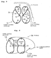
- Fig. 1(a) is a perspective view of an airbag according to an embodiment of the present invention, in an inflated state;
- Fig. 1(b) is a sectional view of the airbag, taken along ling B-B of Fig. 1(a);
- Fig. 2 is a sectional view of the airbag, taken along ling II-II of Fig. 1(b);
- Fig. 3 is a sectional view of the airbag, taken along ling III-III of Fig. 1(b);
- Fig. 4(a) is an exploded perspective view of the airbag;
- Fig. 4(b) is an enlarged view of part B of Fig. 4(a);
- Fig. 5 is a sectional view of an airbag according to another embodiment; and
- FIG. 6 is a sectional perspective view of an airbag according to yet another embodiment.
- the airbag is a passenger airbag to be mounted to the instrument panel of a car in which the left front seat is a passenger seat.
- the left airbag section and the right airbag section are each sometimes simply referred to as a bag.
- the airbag 10 includes a right airbag section 12 that is inflated toward the right front of an occupant (adjacent to the console in this embodiment of Figs. 1 to 4), a left airbag section 14 that is inflated toward the left front of the occupant (adjacent to the car body, and a communicating part 16 that communicates the ends of the right airbag section 12 and the left airbag section 14 with each other.
- the communicating part 16 constructs the base end of the airbag 10.
- the bags 12 and 14 each inflate in the direction remote from the communicating part 16.
- the bags 12 and 14 each include a tether 70 as means for limiting the lateral width of the bags 12 and 14 during inflation.
- the tethers 70 are joined to front inner panels 22 and 24 and front outer panels 26 and 28 that construct the left and right sides of the bags 12 and 14, respectively, with seams 72.
- the tethers 70 are arranged in the vicinity of the vertical center of the bags 12 and 14. In the left airbag section 12, the tether 70 joins the vertical centers of the panels 22 and 26. In the left airbag section 14, a first end of the tether 70 is joined with the vertical center of the panel 24, and a second end is joined with the upper part of the vehicle-side panel 28. In the left airbag section 14, the first end of the tether 70 may be joined with the lower part of the panel 24.
- the part that joins the panel 24 with the first end of the tether 70 range from 40% to 70% from the highest part in the longitudinal section when the height of the longitudinal section (see Fig. 2) of the bag 14 which passes through the tether 70 in a fully inflated condition is H. It is also preferable that the part that joins the panel 28 with the second end of the tether 70 range from 40% to 80% from the lowest part in the longitudinal section. The same applies to a case in which the tether 70 of the right airbag section is inclined, as shown later in Fig. 5.
- the intermediate portion of the right airbag section 12 in the inflating direction and the intermediate portion of the left airbag section 14 in the inflating direction are joined together with seams 52.
- the outer shell of the airbag 10 is constructed of panels 18, 20, 22, 24, 26, and 28.
- the panel 18 constructs the opposing surfaces of the bags 12 and 14 adjacent to the base end and the surface of the communicating part 16 adjacent to the occupant.
- the panel 20 constructs the surface of the bags 12 and 14 opposite to the opposing surfaces thereof and the surface of the communicating part 16 opposite to the occupant.
- the panels 22 and 24 construct the opposing surfaces of the bags 12 and 14.
- the panels 26 and 28 construct the surfaces of the bags 12 and 14 opposite to the opposing surfaces.
- Reference numeral 30 denotes a seam (sewing thread) that stitches up the rear inner panel 18 and the rear outer panel 20 together.
- Reference numerals 32 and 34 denotes seams that sew the rear inner panel 18 on the front inner panels 22 and 24, respectively.
- Reference numerals 36 and 38 denote seams that sew the rear outer panel 20 on the front outer panels 26 and 28, respectively.
- the front outer panels 26 and 28 each have a vent hole 27.
- the stitching tabs (connecting tabs) 44 and 46 for the rear inner panel 18 and the front inner panels 22 and 24 are disposed such that they are exposed to the outer surfaces of the bags 12 and 14.
- tongue-shaped connecting tabs 48 and 50 project from the stitching tabs 44 and 46.
- the connecting tabs 48 and 50 are stitched up together with seams 52.
- the rear outer panel 20 that constructs the outer surface of the communicating part 16 has a pair of slits 54 for an inflator to pass through.
- a rod-like inflator 56 is disposed through the slits 54.
- the airbag 10 is manufactured by the following procedure.
- the rear inner panel 18 and the front inner panels 22 and 24 are stitched up together with seams 32 and 34, respectively, and the rear outer panel 20 and the front outer panels 26 and 28 are stitched up together with seams 36 and 38, respectively.
- the stitching tabs 44 and 46 of the rear inner panel 18 and the front inner panels 22 and 24 are disposed in an airbag product such that they are exposed outside the airbag.
- the stitching tabs 44 of the rear inner panel 18 and the front inner panel 22 are stitched up together only at the both ends with seams 32 (32a and 32b), respectively, as shown in Fig. 4(b). Between the seams 32a and 32b, an opening 60 for the airbag to be reversed is formed.
- the airbag-product intermediate is then turned inside out through the opening 60 of the connecting tabs 44. Thereafter, the connecting tabs 48 and 50 of the stitching tabs 44 and 46 are stitched up together with seams 52, thus completing the airbag 10.
- the airbag 10 is accommodated in the casing in a folded state and joined to the casing with bolts (not shown) inserted in bolt insertion holes 58 (see Fig. 1(b)).
- a lid is mounted on the casing so as to cover the folded airbag 10.
- the airbag system is mounted to an instrument panel ahead of the passenger seat of a car.
- the inflator 56 emits a jet of gas to inflate the right airbag section 12 and the left airbag section 14 on the right and left front of the occupant.
- the lateral widths of the right airbag section 12 and the left airbag section 14 in an inflated condition are limited by the tethers 70 and as such, the inner volumes of the right airbag section 12 and the left airbag section 14 are relatively low. Accordingly, even if the capacity of the inflator 56 is low, the right airbag section 12 and the left airbag section 14 can be inflated sufficiently early.
- the upper part of the left airbag section 14 adjacent to the car body is drawn inward and downward by the tether 70 when inflated. This prevents, as shown in Fig. 2, the upper part of the left airbag section 14 from interfering with the A-pillar and the adjacent windshield, side door, and so forth.
- the intermediate portions of the right airbag section 12 and the left airbag section 14 are joined together with the seams 52. Accordingly, even if one of the bags 12 and 14 inflates first and the other inflates later at the inflation of the airbag 10, the first inflating bag starts to draw the other late inflating bag in the inflating direction relatively early after the start of inflation. Thus, the bags 12 and 14 can be inflated smoothly and substantially evenly from the initial stage of inflation.
- a space 13 is produced between the distal ends of the right airbag section 12 and the left airbag section 14.
- the space 13 is open to the occupant.
- the inflated right airbag section 12 receives the right chest of the occupant, the inflated left airbag section 14 received the left chest, and the space 13 faces the breastbone. Accordingly, the reaction force applied to the breastbone at reception of the airbag is small.
- the distance W between the extreme end 12t of the right airbag section 12 and the extreme end 14t of the left airbag section 14 be in the range from 150 to 450 mm, particularly, from 170 to 430 mm.
- one end of the tether 70 is joined with the upper part of the outer panel (adjacent to the car body) 28 only in the left airbag section 14.
- the tether 70 may be joined with the upper part of the outer panel 26 adjacent to the console, as in a right airbag section 12' of Fig. 5.
- the airbag system can be mounted to both of a car with a lefthand steering and a car with a right-hand steering.
- the volume of the left and right bags may be equal so that the inner pressures during inflation are equal.
- the intermediate portions of the left and right bags 12 and 14 are joined with each other by stitching up the connecting tabs 48 and 50 together.
- the intermediate portions of the left and right bags 12A and 14A may be joined with each other with a belt 80.
- the other numerals of Fig. 6 indicate the same parts as in Figs. 1 to 5.
- a strap, a net, or a panel may be used.
- each of the right airbag section 12 and the left airbag section 14 are each joined together with one tether 70.
- the sides may be joined together with two or more tethers. It is also possible to provide tethers that join the upper surface and the lower surface of each of the right airbag section 12 and the left airbag section 14 to limit the vertical widths of the bags 12 and 14 during inflation.
- the above embodiments are only examples of the invention and so the invention is not limited to the embodiments in the drawings.
- the bags may be separate.
- the left airbag section and the right airbag section may be inflated by separate inflators.
Abstract
Description
- The present invention relates to an airbag and an airbag system for protecting an occupant in a car crash and so on, and in particular, it relates to an airbag and an airbag system including a left airbag section and a right airbag section that are inflated on the left front and right front of an occupant, respectively.
- JP-A-4-292239 (Patent Document 1) discloses an airbag for protecting an occupant in a car crash and so on, which includes a left airbag section and a right airbag section that are inflated on the left front and right front of an occupant, respectively, by a common inflator. In the airbag of the reference, the distal ends of the left airbag section and the right airbag section are joined together with a tie panel.
- The airbag is housed in a casing in a folded condition and covered with a cover. When an inflator (gas generator) is activated to emit a jet of gas in a car crash, the airbag pushes the cover open to inflate toward the front of an occupant.
- The inflator is arranged on the inside or outside of the base end of the airbag. In an airbag system in which the inflator is arranged outside the base end of the airbag, the gas emitted from the inflator is supplied into the airbag through a gas inlet at the base end of the airbag.
- When the inflator is arranged inside the base end of the airbag, the whole of the inflator may be arranged in the airbag, or alternatively, part of the inflator may be arranged in the airbag. The later example includes a structure in which a pair of slit-like openings is provided to the airbag, in which a rod-like inflator is inserted with both ends of the inflator projecting to the exterior of the airbag.
- I. In the airbag including the left airbag section and the right airbag section, disclosed in JP-A-4-292239, when the volumes of the left airbag section and the right airbag section in an inflated condition are high, a high-capacity inflator is required to inflate the airbag early. Accordingly, it is an object of the present invention to provide an airbag and an airbag system in which the left airbag section and the right airbag section are inflated sufficiently early even when the capacity of the inflator is relatively low and in which interference with an A-pillar can be prevented during the inflation.
- II. In the airbag disclosed in JP-A-4-292239, the distal ends of the left airbag section and the right airbag section are joined together with a tie panel. Accordingly, when the airbag inflates, the tie panel receives the lateral center of an occupant's body.
- Accordingly to an embodiment, it is an object of the invention to provide an airbag and an airbag system in which the inflated left airbag section receives the left chest of an occupant and the right airbag section receives the right chest and in which the space of the inflated airbag faces the lateral center of the occupant's chest.
- III. In the airbag disclosed in JP-A-4-292239, when the left airbag section and the right airbag section inflate, the gas from the inflator flows more into one of the airbag sections than the other, so that the other airbag section might inflate later than the first airbag section.
- In the airbag disclosed in the reference, the left airbag section and the right airbag section are joined together with a tie panel. Accordingly, even if one of the airbag sections inflates later than the other, the first inflating airbag section may draw the late inflating airbag section in the inflating direction with the tie panel to accelerate its inflation. However, since the tie panel connects the distal ends of the left airbag section and the right airbag section together, the first inflating airbag section cannot sufficiently draw the late inflating airbag with the tie panel until it inflates to the distal end.
- According to another embodiment, it is an object of the invention to provide an airbag and an airbag system in which both of the left airbag section and the right airbag section are inflated smoothly and substantially evenly from the initial stage of inflation.
- An airbag according to the invention (Claim 1) is an airbag that is inflated in the direction in which the distal end moves away from the base end with gas emitted from an inflator disposed on the base end thereof. The airbag includes a left airbag section that is inflated toward the left front of an occupant, and a right airbag section that is inflated toward the right front of the occupant. The airbag further includes width limiting means for limiting the lateral widths of the left airbag section and the right airbag section during inflation. In at least one of the left airbag section and the right airbag section, the width limiting means draws the upper part of the bag adjacent to the car body inward and downward.
- The airbag according to Claim 2, in
Claim 1, the width limiting means is a tether that joins the upper part of the bag adjacent to the car body with the vertical intermediate portion or the lower part of the bag opposite thereto. - The airbag according to Claim 3, in
Claims 1 or 2, the distal ends of the left airbag section and the right airbag section are not joined with each other, and a space open to the occupant is formed between the distal ends of the left airbag section and the right airbag section with the airbag in an inflated state. - The airbag according to Claim 4, in one of
Claims 1 to 3, the intermediate portions of the left airbag section and the right airbag section in the inflating direction are joined with each other. - The airbag according to Claim 5, in Claim 4, the opposing portions of the left airbag section and the right airbag section are joined with each other with a connecting member extending in the direction of connection thereof.
- An airbag system according to the invention (Claim 6) includes the airbag according to the invention and an inflator for inflating the airbag.
- With the airbag and the airbag system according to embodiments of the invention, the lateral widths of the airbags in an inflated condition are limited. Accordingly, even if a low-capacity inflator is adopted, the right airbag section and the left airbag section can be inflated sufficiently early. According to the invention, the upper part of the bag adjacent to the car body is drawn inward and downward. This prevents the upper part of the inflated bag adjacent to the car body from interfering with the A-pillar and adjacent members.
- It is preferable that the width limiting means be a tether that joins the upper part of the bag adjacent to the car body with the intermediate portion or the lower part of the bag opposite thereto. By controlling the length of the tether, the inward and downward drawing amount of the upper part of the inflated airbag adjacent to the car body can be easily set.
- According to the invention, the distal ends of the left airbag section and the right airbag section may not be joined with each other; and a space open to the occupant may be formed between the distal ends of the left airbag section and the right airbag section with the airbag in an inflated state.
- When the airbag is inflated, the left airbag section receives the left chest of the occupant and the right airbag section received the right chest. The left and right chest has hard and strong ribs. The airbag receives and absorbs the impact of the occupant via the ribs. With the airbag in an inflated state, a space is produced between the distal ends of the right airbag section and the left airbag section. The breastbone in the center of the breast of the occupant faces the space. Accordingly, when the body of the occupant strikes against the airbag, the breastbone receives little reaction force from the airbag, thus receiving little load.
- According to an embodiment of the invention, the intermediate portions of the left airbag section and the right airbag section in the inflating direction are joined with each other.
- With the intermediate portions joined together, even if one of the airbag sections inflates later than the other, the first inflating airbag section draws the other late inflating airbag section to accelerate its inflation. Moreover, the intermediate portions of the left airbag section and the right airbag section in the inflating direction are joined with each other. Accordingly, the bag that has first started inflation draws the other late inflating bag in the inflating direction at the initial stage of inflation halfway through inflation. Thus, both of the left airbag section and the right airbag section can be inflated smoothly and substantially evenly from the initial stage of inflation.
- In the airbag in which the intermediate portions of the left airbag section and the right airbag section in the inflating direction are joined together, the opposing portions of the left airbag section and the right airbag section may be joined with each other with a connecting member extending in the direction of connection thereof. With such a structure, the distance between the left airbag section and the right airbag section in an inflated state can be limited by the length of the connecting member.
- The present invention is described in detail below based on embodiments, with reference to the attached drawings.
-
Fig. 1(a) is a perspective view of an airbag according to an embodiment of the present invention, in an inflated state;
Fig. 1(b) is a sectional view of the airbag, taken along ling B-B of Fig. 1(a);
Fig. 2 is a sectional view of the airbag, taken along ling II-II of Fig. 1(b);
Fig. 3 is a sectional view of the airbag, taken along ling III-III of Fig. 1(b);
Fig. 4(a) is an exploded perspective view of the airbag;
Fig. 4(b) is an enlarged view of part B of Fig. 4(a);
Fig. 5 is a sectional view of an airbag according to another embodiment; and
Fig. 6 is a sectional perspective view of an airbag according to yet another embodiment.
The airbag is a passenger airbag to be mounted to the instrument panel of a car in which the left front seat is a passenger seat. Hereinafter, the left airbag section and the right airbag section are each sometimes simply referred to as a bag. - The
airbag 10 includes aright airbag section 12 that is inflated toward the right front of an occupant (adjacent to the console in this embodiment of Figs. 1 to 4), aleft airbag section 14 that is inflated toward the left front of the occupant (adjacent to the car body, and a communicatingpart 16 that communicates the ends of theright airbag section 12 and theleft airbag section 14 with each other. The communicatingpart 16 constructs the base end of theairbag 10. Thebags part 16. - The
bags tether 70 as means for limiting the lateral width of thebags tethers 70 are joined to frontinner panels outer panels bags - The
tethers 70 are arranged in the vicinity of the vertical center of thebags left airbag section 12, thetether 70 joins the vertical centers of thepanels left airbag section 14, a first end of thetether 70 is joined with the vertical center of thepanel 24, and a second end is joined with the upper part of the vehicle-side panel 28. In theleft airbag section 14, the first end of thetether 70 may be joined with the lower part of thepanel 24. - It is preferable that the part that joins the
panel 24 with the first end of thetether 70 range from 40% to 70% from the highest part in the longitudinal section when the height of the longitudinal section (see Fig. 2) of thebag 14 which passes through thetether 70 in a fully inflated condition is H. It is also preferable that the part that joins thepanel 28 with the second end of thetether 70 range from 40% to 80% from the lowest part in the longitudinal section. The same applies to a case in which thetether 70 of the right airbag section is inclined, as shown later in Fig. 5. - When the
right airbag section 12 and theleft airbag section 14 are inflated, the widths are limited by thetethers 70. - In the
airbag 10, the intermediate portion of theright airbag section 12 in the inflating direction and the intermediate portion of theleft airbag section 14 in the inflating direction are joined together withseams 52. - In this embodiment, the outer shell of the
airbag 10 is constructed ofpanels - The panel 18 (rear inner panel) constructs the opposing surfaces of the
bags part 16 adjacent to the occupant. The panel 20 (rear outer panel) constructs the surface of thebags part 16 opposite to the occupant. - The
panels 22 and 24 (front inner panels) construct the opposing surfaces of thebags - The
panels 26 and 28 (front outer panels) construct the surfaces of thebags -
Reference numeral 30 denotes a seam (sewing thread) that stitches up the rearinner panel 18 and the rearouter panel 20 together.Reference numerals inner panel 18 on the frontinner panels Reference numerals outer panel 20 on the frontouter panels - The front
outer panels vent hole 27. - As shown in Fig. 1(a), the stitching tabs (connecting tabs) 44 and 46 for the rear
inner panel 18 and the frontinner panels bags tabs stitching tabs tabs seams 52. - The rear
outer panel 20 that constructs the outer surface of the communicatingpart 16 has a pair ofslits 54 for an inflator to pass through. A rod-like inflator 56 is disposed through theslits 54. - The
airbag 10 is manufactured by the following procedure. - As shown in Fig. 4(a), the rear
inner panel 18 and the frontinner panels seams outer panel 20 and the frontouter panels seams stitching tabs inner panel 18 and the frontinner panels - In this embodiment, the
stitching tabs 44 of the rearinner panel 18 and the frontinner panel 22 are stitched up together only at the both ends with seams 32 (32a and 32b), respectively, as shown in Fig. 4(b). Between theseams opening 60 for the airbag to be reversed is formed. - Then the stitched body of the rear
inner panel 18 and the frontinner panels outer panel 20 and the frontouter panels seams tether 70 are sewn on thepanels panels - The airbag-product intermediate is then turned inside out through the
opening 60 of the connectingtabs 44. Thereafter, the connectingtabs stitching tabs seams 52, thus completing theairbag 10. - When the connecting
tabs opening 60 is closed by theseams 52. - The
airbag 10 is accommodated in the casing in a folded state and joined to the casing with bolts (not shown) inserted in bolt insertion holes 58 (see Fig. 1(b)). A lid is mounted on the casing so as to cover the foldedairbag 10. - The airbag system is mounted to an instrument panel ahead of the passenger seat of a car. In a car crash, the
inflator 56 emits a jet of gas to inflate theright airbag section 12 and theleft airbag section 14 on the right and left front of the occupant. - In the
airbag 10, the lateral widths of theright airbag section 12 and theleft airbag section 14 in an inflated condition are limited by thetethers 70 and as such, the inner volumes of theright airbag section 12 and theleft airbag section 14 are relatively low. Accordingly, even if the capacity of the inflator 56 is low, theright airbag section 12 and theleft airbag section 14 can be inflated sufficiently early. - In this embodiment, the upper part of the
left airbag section 14 adjacent to the car body is drawn inward and downward by thetether 70 when inflated. This prevents, as shown in Fig. 2, the upper part of theleft airbag section 14 from interfering with the A-pillar and the adjacent windshield, side door, and so forth. - The intermediate portions of the
right airbag section 12 and theleft airbag section 14 are joined together with theseams 52. Accordingly, even if one of thebags airbag 10, the first inflating bag starts to draw the other late inflating bag in the inflating direction relatively early after the start of inflation. Thus, thebags - With the
airbag 10 in a fully inflated state, aspace 13 is produced between the distal ends of theright airbag section 12 and theleft airbag section 14. Thespace 13 is open to the occupant. The inflatedright airbag section 12 receives the right chest of the occupant, the inflatedleft airbag section 14 received the left chest, and thespace 13 faces the breastbone. Accordingly, the reaction force applied to the breastbone at reception of the airbag is small. - With the
airbag 10 in a fully inflated state, it is preferable that the distance W between theextreme end 12t of theright airbag section 12 and theextreme end 14t of theleft airbag section 14 be in the range from 150 to 450 mm, particularly, from 170 to 430 mm. - In the foregoing embodiments, one end of the
tether 70 is joined with the upper part of the outer panel (adjacent to the car body) 28 only in theleft airbag section 14. However, thetether 70 may be joined with the upper part of theouter panel 26 adjacent to the console, as in a right airbag section 12' of Fig. 5. With such a structure, the airbag system can be mounted to both of a car with a lefthand steering and a car with a right-hand steering. The volume of the left and right bags may be equal so that the inner pressures during inflation are equal. - In the foregoing embodiments, the intermediate portions of the left and
right bags tabs right bags belt 80. The other numerals of Fig. 6 indicate the same parts as in Figs. 1 to 5. In place of thebelt 80, a strap, a net, or a panel may be used. - In the foregoing embodiments, the left and right sides of each of the
right airbag section 12 and theleft airbag section 14 are each joined together with onetether 70. Alternatively, the sides may be joined together with two or more tethers. It is also possible to provide tethers that join the upper surface and the lower surface of each of theright airbag section 12 and theleft airbag section 14 to limit the vertical widths of thebags - The above embodiments are only examples of the invention and so the invention is not limited to the embodiments in the drawings. For example, although the right airbag section and the left airbag section of the embodiment connect to each other at the base ends, the bags may be separate. The left airbag section and the right airbag section may be inflated by separate inflators.
Claims (6)
- An airbag that is inflated in the direction in which the distal end moves away from the base end with gas emitted from an inflator disposed on the base end thereof, the airbag comprising:a left airbag section that is inflated toward the left front of an occupant; anda right airbag section that is inflated toward the right front of the occupant; the airbag includingwidth limiting means for limiting the lateral widths of the left airbag section and the right airbag section during inflation, whereinin at least one of the left airbag section and the right airbag section, the width limiting means draws the upper part of the bag adjacent to the car body inward and downward.
- The airbag according to Claim 1, wherein the width limiting means is a tether that joins the upper part of the bag adjacent to the car body with the vertical intermediate portion or the lower part of the bag opposite thereto.
- The airbag according to Claim 1 or 2, wherein
the distal ends of the left airbag section and the right airbag section are not joined with each other; and
a space open to the occupant is formed between the distal ends of the left airbag section and the right airbag section with the airbag in an inflated state. - The airbag according to one of Claims 1 to 3, wherein the intermediate portions of the left airbag section and the right airbag section in the inflating direction are joined with each other.
- The airbag according to Claim 4, wherein the opposing portions of the left airbag section and the right airbag section are joined with each other with a connecting member extending in the direction of connection thereof.
- An airbag system including an airbag and an inflator for inflating the airbag, wherein
the airbag is the airbag according to one of Claims 1 to 5.
Applications Claiming Priority (1)
| Application Number | Priority Date | Filing Date | Title |
|---|---|---|---|
| JP2004243936A JP4622386B2 (en) | 2004-08-24 | 2004-08-24 | Air bag and air bag device |
Publications (2)
| Publication Number | Publication Date |
|---|---|
| EP1630044A1 true EP1630044A1 (en) | 2006-03-01 |
| EP1630044B1 EP1630044B1 (en) | 2008-06-25 |
Family
ID=35106912
Family Applications (1)
| Application Number | Title | Priority Date | Filing Date |
|---|---|---|---|
| EP05014877A Expired - Fee Related EP1630044B1 (en) | 2004-08-24 | 2005-07-08 | Airbag and airbag system |
Country Status (5)
| Country | Link |
|---|---|
| US (1) | US7461862B2 (en) |
| EP (1) | EP1630044B1 (en) |
| JP (1) | JP4622386B2 (en) |
| CN (1) | CN1740011A (en) |
| DE (1) | DE602005007666D1 (en) |
Cited By (1)
| Publication number | Priority date | Publication date | Assignee | Title |
|---|---|---|---|---|
| CN101626922B (en) * | 2007-03-14 | 2012-04-18 | 高田株式会社 | Method of manufacturing airbag |
Families Citing this family (18)
| Publication number | Priority date | Publication date | Assignee | Title |
|---|---|---|---|---|
| US6703897B2 (en) * | 2001-12-26 | 2004-03-09 | Nortel Networks Limited | Methods of optimising power amplifier efficiency and closed-loop power amplifier controllers |
| JP4760158B2 (en) * | 2005-06-24 | 2011-08-31 | タカタ株式会社 | Air bag and air bag device |
| US7152880B1 (en) | 2005-10-17 | 2006-12-26 | Key Safety Systems, Inc. | Grooved air bag |
| US7625008B2 (en) * | 2005-10-17 | 2009-12-01 | Key Safety Systems, Inc. | Air bag with groove or recess, open or partially covered |
| JP4954577B2 (en) * | 2006-03-15 | 2012-06-20 | 本田技研工業株式会社 | Vehicle airbag device |
| JP4793104B2 (en) * | 2006-06-01 | 2011-10-12 | 豊田合成株式会社 | Side airbag device |
| JP4743014B2 (en) * | 2006-06-21 | 2011-08-10 | 豊田合成株式会社 | Passenger airbag |
| JP4847258B2 (en) * | 2006-09-07 | 2011-12-28 | タカタ株式会社 | Airbag device |
| EP2090474B1 (en) * | 2006-09-22 | 2012-06-27 | Autoliv Development AB | Method of manufacturing airbag and airbag |
| US7946619B2 (en) * | 2008-01-31 | 2011-05-24 | Tk Holdings Inc. | Airbag |
| US8047564B2 (en) * | 2009-09-02 | 2011-11-01 | Tk Holdings Inc. | Airbag |
| US8657334B2 (en) | 2011-02-11 | 2014-02-25 | Key Safety Systems, Inc. | Airbag cushion |
| JP2012179956A (en) | 2011-02-28 | 2012-09-20 | Fuji Heavy Ind Ltd | Occupant protection apparatus and occupant protection method |
| JP6075935B2 (en) * | 2011-02-28 | 2017-02-08 | 富士重工業株式会社 | Occupant protection device and occupant protection method |
| JP5401495B2 (en) * | 2011-03-17 | 2014-01-29 | 富士重工業株式会社 | Side airbag device, occupant protection device, and occupant protection method |
| JP2016040155A (en) * | 2014-08-12 | 2016-03-24 | 豊田合成株式会社 | Airbag device for front passenger seat |
| US9937890B2 (en) | 2014-12-24 | 2018-04-10 | Tk Holdings Inc. | Side impact airbag module |
| US9789844B2 (en) * | 2015-11-02 | 2017-10-17 | Ford Global Technologies, Llc | Dual chamber airbag with asymmetrically tunable parameters and method of manufacturing the same |
Citations (3)
| Publication number | Priority date | Publication date | Assignee | Title |
|---|---|---|---|---|
| JPH04292239A (en) | 1991-03-20 | 1992-10-16 | Asahi Chem Ind Co Ltd | Air bag for vehicle |
| US20040160048A1 (en) * | 2003-02-18 | 2004-08-19 | Takata Corporation | Airbag device |
| EP1452403A1 (en) * | 2003-02-26 | 2004-09-01 | Takata Corporation | Airbag |
Family Cites Families (22)
| Publication number | Priority date | Publication date | Assignee | Title |
|---|---|---|---|---|
| JPS4923176B1 (en) * | 1970-09-24 | 1974-06-13 | ||
| US3879056A (en) * | 1972-02-21 | 1975-04-22 | Toyoda Boshoku Kk | Safety gas bag structure |
| JPS4923176A (en) | 1972-06-26 | 1974-03-01 | ||
| JPH0332956A (en) * | 1989-06-30 | 1991-02-13 | Mazda Motor Corp | Air bag device for automobile |
| JPH0456655A (en) * | 1990-06-27 | 1992-02-24 | Takata Kk | Air bag |
| US5290061A (en) * | 1992-10-14 | 1994-03-01 | Trw Vehicle Safety Systems Inc. | Folded air bag |
| JP2603245Y2 (en) * | 1993-02-19 | 2000-03-06 | 日産車体株式会社 | Passenger airbag |
| JP3124651B2 (en) | 1993-03-29 | 2001-01-15 | 日産車体株式会社 | Passenger airbag |
| US5380038A (en) * | 1993-11-01 | 1995-01-10 | General Motors Corporation | Offset inflatable restraint system |
| JP3760424B2 (en) | 1996-08-30 | 2006-03-29 | 本田技研工業株式会社 | Airbag device for vehicle |
| JP3591289B2 (en) * | 1998-03-30 | 2004-11-17 | 日産自動車株式会社 | Airbag device for automobile side collision |
| JP4608072B2 (en) * | 2000-02-25 | 2011-01-05 | タカタ株式会社 | Airbag device |
| DE10033937C2 (en) * | 2000-07-05 | 2002-09-26 | Takata Petri Ag | Airbag for an occupant protection device |
| EP1172263B1 (en) * | 2000-07-13 | 2005-12-14 | TRW Automotive Safety Systems GmbH | Airbag module with an airbag front wall comprising a recess |
| JP2002104119A (en) * | 2000-09-28 | 2002-04-10 | Nippon Plast Co Ltd | Air bag device for automobile |
| DE20022018U1 (en) * | 2000-12-28 | 2001-11-08 | Trw Automotive Safety Sys Gmbh | Airbag restraint |
| DE20022020U1 (en) * | 2000-12-28 | 2001-11-08 | Trw Automotive Safety Sys Gmbh | Airbag module |
| JP2003170796A (en) * | 2001-12-06 | 2003-06-17 | Takata Corp | Airbag |
| US6883832B2 (en) * | 2002-01-30 | 2005-04-26 | Trw Automotive Safety Systems Gmbh | Gas bag for a vehicle occupant restraint system and a gas bag module |
| JP4274742B2 (en) * | 2002-05-22 | 2009-06-10 | タカタ株式会社 | Air bag and air bag device |
| US7121584B2 (en) * | 2003-01-24 | 2006-10-17 | Takata Corporation | Airbag and airbag apparatus |
| JP4388313B2 (en) * | 2003-06-19 | 2009-12-24 | タカタ株式会社 | Airbag device, motorcycle with airbag device |
-
2004
- 2004-08-24 JP JP2004243936A patent/JP4622386B2/en not_active Expired - Fee Related
-
2005
- 2005-07-08 DE DE602005007666T patent/DE602005007666D1/en active Active
- 2005-07-08 EP EP05014877A patent/EP1630044B1/en not_active Expired - Fee Related
- 2005-08-18 US US11/206,204 patent/US7461862B2/en not_active Expired - Fee Related
- 2005-08-24 CN CNA2005100965458A patent/CN1740011A/en active Pending
Patent Citations (3)
| Publication number | Priority date | Publication date | Assignee | Title |
|---|---|---|---|---|
| JPH04292239A (en) | 1991-03-20 | 1992-10-16 | Asahi Chem Ind Co Ltd | Air bag for vehicle |
| US20040160048A1 (en) * | 2003-02-18 | 2004-08-19 | Takata Corporation | Airbag device |
| EP1452403A1 (en) * | 2003-02-26 | 2004-09-01 | Takata Corporation | Airbag |
Non-Patent Citations (1)
| Title |
|---|
| PATENT ABSTRACTS OF JAPAN vol. 017, no. 099 (M - 1373) 26 February 1993 (1993-02-26) * |
Cited By (1)
| Publication number | Priority date | Publication date | Assignee | Title |
|---|---|---|---|---|
| CN101626922B (en) * | 2007-03-14 | 2012-04-18 | 高田株式会社 | Method of manufacturing airbag |
Also Published As
| Publication number | Publication date |
|---|---|
| DE602005007666D1 (en) | 2008-08-07 |
| EP1630044B1 (en) | 2008-06-25 |
| JP2006062394A (en) | 2006-03-09 |
| US20060043707A1 (en) | 2006-03-02 |
| CN1740011A (en) | 2006-03-01 |
| US7461862B2 (en) | 2008-12-09 |
| JP4622386B2 (en) | 2011-02-02 |
Similar Documents
| Publication | Publication Date | Title |
|---|---|---|
| EP1630044B1 (en) | Airbag and airbag system | |
| US7390020B2 (en) | Airbag and airbag apparatus | |
| JP4400188B2 (en) | Air bag, air bag device and vehicle | |
| US7458605B2 (en) | Airbag, airbag system and vehicle | |
| US7648158B2 (en) | Twin airbag | |
| EP1671852B1 (en) | Airbag and airbag system | |
| US7152877B2 (en) | Airbag and airbag apparatus | |
| JP4760158B2 (en) | Air bag and air bag device | |
| US7267366B2 (en) | Airbag, airbag device and vehicle | |
| US6394487B1 (en) | Inflatable airbag | |
| EP1452403B1 (en) | Airbag | |
| US20060103118A1 (en) | Twin airbag | |
| US6969086B2 (en) | Airbag and airbag device | |
| US7163229B2 (en) | Occupant protection device and vehicle | |
| US20040145161A1 (en) | Airbag and airbag apparatus | |
| CN109693635B (en) | Airbag device | |
| US20070045998A1 (en) | Driver leg restraint apparatus | |
| JP2000142303A (en) | Air bag device for head protection | |
| JP4337519B2 (en) | Air bag and air bag device | |
| JP3772742B2 (en) | Air bag device for knee protection | |
| JP2000159045A (en) | Air bag and its manufacture | |
| JP4367120B2 (en) | Passenger seat airbag, passenger seat airbag apparatus and vehicle | |
| JP2017149178A (en) | Side airbag device | |
| JP5424947B2 (en) | Airbag | |
| EP1630047B1 (en) | Airbag and airbag apparatus |
Legal Events
| Date | Code | Title | Description |
|---|---|---|---|
| PUAI | Public reference made under article 153(3) epc to a published international application that has entered the european phase |
Free format text: ORIGINAL CODE: 0009012 |
|
| AK | Designated contracting states |
Kind code of ref document: A1 Designated state(s): AT BE BG CH CY CZ DE DK EE ES FI FR GB GR HU IE IS IT LI LT LU LV MC NL PL PT RO SE SI SK TR |
|
| AX | Request for extension of the european patent |
Extension state: AL BA HR MK YU |
|
| 17P | Request for examination filed |
Effective date: 20060801 |
|
| 17Q | First examination report despatched |
Effective date: 20061009 |
|
| AKX | Designation fees paid |
Designated state(s): DE FR GB SE |
|
| 17Q | First examination report despatched |
Effective date: 20061009 |
|
| GRAP | Despatch of communication of intention to grant a patent |
Free format text: ORIGINAL CODE: EPIDOSNIGR1 |
|
| GRAS | Grant fee paid |
Free format text: ORIGINAL CODE: EPIDOSNIGR3 |
|
| GRAA | (expected) grant |
Free format text: ORIGINAL CODE: 0009210 |
|
| RIN1 | Information on inventor provided before grant (corrected) |
Inventor name: HASEBE, MASAHIROTAKATA CORPORATION Inventor name: NARIMOTO, YUKITOSHITAKATA CORPORATION |
|
| AK | Designated contracting states |
Kind code of ref document: B1 Designated state(s): DE FR GB SE |
|
| REG | Reference to a national code |
Ref country code: GB Ref legal event code: FG4D |
|
| REF | Corresponds to: |
Ref document number: 602005007666 Country of ref document: DE Date of ref document: 20080807 Kind code of ref document: P |
|
| PG25 | Lapsed in a contracting state [announced via postgrant information from national office to epo] |
Ref country code: SE Free format text: LAPSE BECAUSE OF FAILURE TO SUBMIT A TRANSLATION OF THE DESCRIPTION OR TO PAY THE FEE WITHIN THE PRESCRIBED TIME-LIMIT Effective date: 20080925 |
|
| PLBE | No opposition filed within time limit |
Free format text: ORIGINAL CODE: 0009261 |
|
| STAA | Information on the status of an ep patent application or granted ep patent |
Free format text: STATUS: NO OPPOSITION FILED WITHIN TIME LIMIT |
|
| 26N | No opposition filed |
Effective date: 20090326 |
|
| REG | Reference to a national code |
Ref country code: FR Ref legal event code: ST Effective date: 20090529 |
|
| PG25 | Lapsed in a contracting state [announced via postgrant information from national office to epo] |
Ref country code: FR Free format text: LAPSE BECAUSE OF NON-PAYMENT OF DUE FEES Effective date: 20080731 |
|
| PGFP | Annual fee paid to national office [announced via postgrant information from national office to epo] |
Ref country code: DE Payment date: 20130703 Year of fee payment: 9 |
|
| PGFP | Annual fee paid to national office [announced via postgrant information from national office to epo] |
Ref country code: GB Payment date: 20130703 Year of fee payment: 9 |
|
| REG | Reference to a national code |
Ref country code: DE Ref legal event code: R119 Ref document number: 602005007666 Country of ref document: DE |
|
| GBPC | Gb: european patent ceased through non-payment of renewal fee |
Effective date: 20140708 |
|
| PG25 | Lapsed in a contracting state [announced via postgrant information from national office to epo] |
Ref country code: DE Free format text: LAPSE BECAUSE OF NON-PAYMENT OF DUE FEES Effective date: 20150203 |
|
| REG | Reference to a national code |
Ref country code: DE Ref legal event code: R119 Ref document number: 602005007666 Country of ref document: DE Effective date: 20150203 |
|
| PG25 | Lapsed in a contracting state [announced via postgrant information from national office to epo] |
Ref country code: GB Free format text: LAPSE BECAUSE OF NON-PAYMENT OF DUE FEES Effective date: 20140708 |