EP1630029A1 - Vorrichtung zur Messung des Drehmoments am Abtrieb eines Verteilergetriebes eines Kraftfahrzeuges - Google Patents
Vorrichtung zur Messung des Drehmoments am Abtrieb eines Verteilergetriebes eines Kraftfahrzeuges Download PDFInfo
- Publication number
- EP1630029A1 EP1630029A1 EP05103682A EP05103682A EP1630029A1 EP 1630029 A1 EP1630029 A1 EP 1630029A1 EP 05103682 A EP05103682 A EP 05103682A EP 05103682 A EP05103682 A EP 05103682A EP 1630029 A1 EP1630029 A1 EP 1630029A1
- Authority
- EP
- European Patent Office
- Prior art keywords
- transfer case
- sensor means
- measuring
- output shaft
- force
- Prior art date
- Legal status (The legal status is an assumption and is not a legal conclusion. Google has not performed a legal analysis and makes no representation as to the accuracy of the status listed.)
- Granted
Links
- 238000012546 transfer Methods 0.000 title claims description 31
- 238000005259 measurement Methods 0.000 claims abstract description 17
- 238000011156 evaluation Methods 0.000 claims description 17
- 239000000919 ceramic Substances 0.000 claims description 2
- 239000000758 substrate Substances 0.000 claims description 2
- 230000008878 coupling Effects 0.000 description 5
- 238000010168 coupling process Methods 0.000 description 5
- 238000005859 coupling reaction Methods 0.000 description 5
- 230000001133 acceleration Effects 0.000 description 3
- 230000005540 biological transmission Effects 0.000 description 3
- 238000006243 chemical reaction Methods 0.000 description 3
- 238000012937 correction Methods 0.000 description 3
- 238000009434 installation Methods 0.000 description 2
- 238000000691 measurement method Methods 0.000 description 2
- 238000000034 method Methods 0.000 description 2
- 238000005452 bending Methods 0.000 description 1
- 238000002485 combustion reaction Methods 0.000 description 1
- 230000001419 dependent effect Effects 0.000 description 1
- 238000010586 diagram Methods 0.000 description 1
- 230000000694 effects Effects 0.000 description 1
- 238000005516 engineering process Methods 0.000 description 1
- 230000007613 environmental effect Effects 0.000 description 1
- 239000000463 material Substances 0.000 description 1
- ZMRUPTIKESYGQW-UHFFFAOYSA-N propranolol hydrochloride Chemical compound [H+].[Cl-].C1=CC=C2C(OCC(O)CNC(C)C)=CC=CC2=C1 ZMRUPTIKESYGQW-UHFFFAOYSA-N 0.000 description 1
- 230000002277 temperature effect Effects 0.000 description 1
Images



Classifications
-
- F—MECHANICAL ENGINEERING; LIGHTING; HEATING; WEAPONS; BLASTING
- F16—ENGINEERING ELEMENTS AND UNITS; GENERAL MEASURES FOR PRODUCING AND MAINTAINING EFFECTIVE FUNCTIONING OF MACHINES OR INSTALLATIONS; THERMAL INSULATION IN GENERAL
- F16H—GEARING
- F16H59/00—Control inputs to control units of change-speed- or reversing-gearings for conveying rotary motion
- F16H59/14—Inputs being a function of torque or torque demand
- F16H59/16—Dynamometric measurement of torque
-
- G—PHYSICS
- G01—MEASURING; TESTING
- G01L—MEASURING FORCE, STRESS, TORQUE, WORK, MECHANICAL POWER, MECHANICAL EFFICIENCY, OR FLUID PRESSURE
- G01L5/00—Apparatus for, or methods of, measuring force, work, mechanical power, or torque, specially adapted for specific purposes
- G01L5/0009—Force sensors associated with a bearing
- G01L5/0019—Force sensors associated with a bearing by using strain gages, piezoelectric, piezo-resistive or other ohmic-resistance based sensors
-
- B—PERFORMING OPERATIONS; TRANSPORTING
- B60—VEHICLES IN GENERAL
- B60K—ARRANGEMENT OR MOUNTING OF PROPULSION UNITS OR OF TRANSMISSIONS IN VEHICLES; ARRANGEMENT OR MOUNTING OF PLURAL DIVERSE PRIME-MOVERS IN VEHICLES; AUXILIARY DRIVES FOR VEHICLES; INSTRUMENTATION OR DASHBOARDS FOR VEHICLES; ARRANGEMENTS IN CONNECTION WITH COOLING, AIR INTAKE, GAS EXHAUST OR FUEL SUPPLY OF PROPULSION UNITS IN VEHICLES
- B60K23/00—Arrangement or mounting of control devices for vehicle transmissions, or parts thereof, not otherwise provided for
- B60K23/08—Arrangement or mounting of control devices for vehicle transmissions, or parts thereof, not otherwise provided for for changing number of driven wheels, for switching from driving one axle to driving two or more axles
- B60K23/0808—Arrangement or mounting of control devices for vehicle transmissions, or parts thereof, not otherwise provided for for changing number of driven wheels, for switching from driving one axle to driving two or more axles for varying torque distribution between driven axles, e.g. by transfer clutch
-
- B—PERFORMING OPERATIONS; TRANSPORTING
- B60—VEHICLES IN GENERAL
- B60W—CONJOINT CONTROL OF VEHICLE SUB-UNITS OF DIFFERENT TYPE OR DIFFERENT FUNCTION; CONTROL SYSTEMS SPECIALLY ADAPTED FOR HYBRID VEHICLES; ROAD VEHICLE DRIVE CONTROL SYSTEMS FOR PURPOSES NOT RELATED TO THE CONTROL OF A PARTICULAR SUB-UNIT
- B60W2510/00—Input parameters relating to a particular sub-units
- B60W2510/10—Change speed gearings
- B60W2510/105—Output torque
-
- F—MECHANICAL ENGINEERING; LIGHTING; HEATING; WEAPONS; BLASTING
- F16—ENGINEERING ELEMENTS AND UNITS; GENERAL MEASURES FOR PRODUCING AND MAINTAINING EFFECTIVE FUNCTIONING OF MACHINES OR INSTALLATIONS; THERMAL INSULATION IN GENERAL
- F16H—GEARING
- F16H7/00—Gearings for conveying rotary motion by endless flexible members
- F16H7/06—Gearings for conveying rotary motion by endless flexible members with chains
Definitions
- the invention relates to a device for measuring the torque at the output of a transfer case of a motor vehicle, wherein an input shaft and an output shaft are respectively mounted end support bearings in the transfer case, wherein a belt drive is guided over the input shaft and the output shaft, so that the path of the power flow to Supporting the tensile force of the belt drive occurring during operation is guided via these support bearings and via force-conducting regions of the transfer case housing.
- a transfer case of a motor vehicle has the task of dividing the total drive power generated by the engine into two partial drive powers between the front axle and the rear axle of the four-wheel drive vehicle. This division of the total drive power corresponds to a variable torque distribution, which must be adapted to the prevailing driving conditions and to the desired performance of the vehicle driver.
- the transfer case has an actuator, which is usually operated by an electromechanical actuator.
- the electromechanical actuator usually consists of a DC actuator, which is in a closed loop control.
- For the electronic control in the control loop that at the output of the transfer case actually issued Torque is an input that can be determined by an indirect or direct measurement method.
- An indirect measuring method is, for example, the measurement of the armature current of the direct current servomotor, from which the desired torque at the output of the transfer case is then determined.
- the problem arises that, due to the very short positioning movements, the armature current of the direct-current servo motor primarily reflects the mechanical torque required for the rotational acceleration and not the required actuating force.
- the measurement result is distorted by tolerances of the actuating mechanism and by the wear of the entire transfer case.
- a direct measurement method as proposed for example in US 4619 6 29 for the torque measurement on an input shaft and an output shaft of an automatic transmission, but is correspondingly expensive and prone to failure.
- the invention is based on the object to provide a torque measuring device, with the aid of which the torque at the output of a transfer case can be detected easily and with high reliability and which can be produced with reasonable effort.
- the measurement of the torque at the output of a Transfer case via a measurement of the tensile force is provided.
- a sensor means is provided for detecting this tensile force, which is arranged in the path of the force flow of the supporting force.
- the sensor means generates at the output an electrical signal, which is supplied to an evaluation unit.
- the evaluation unit has a suitable arithmetic unit, for example a microcomputer, so that the emitted mechanical torque can be calculated from this measurement signal.
- a significant advantage of the invention is that the measurement signal does not have to be removed from moving parts, such as from a torque shaft, but by a stationary mounted force transducer. This allows a simple and largely interference-free signal evaluation. Compared with the indirect measuring method of the armature current of the DC servo motor, the invention achieves a much more accurate result.
- the force transducer is arranged in the path of the power flow of the support between input and output shaft.
- a preferred embodiment of the invention provides that the sensor means is formed by a trained as a measuring bearing support bearing of the output shaft.
- a measuring bearing is a shaft bearing with load cell, which can be structurally implemented, for example, according to DE 43 13 862 C1 or DE 36 03 187 C2.
- Such bearings are commercially available.
- a further preferred embodiment of the invention is characterized in that the sensor means comprises a strain gauge, which is arranged in a bearing retaining ring of the support bearing of the output shaft. This can be used as a support bearing commercial bearings.
- a structural embodiment of such a measuring unit is known for example from DE 30 09 454 A1.
- the elastically deformable measuring zone can be structurally different. It can for example consist of a bending beam, which is formed by a recess in the housing wall and which is provided with strain gauges exist.
- the sensor means comprises a force transducer, which operates on a resistive, capacitive or piezoelectric measuring principle.
- the force transmitter and the evaluation unit are advantageously arranged in local proximity to the measurement zone. Due to the short connection cables and the Sinal evaluation on site, the measurement result is less susceptible to electromagnetic interference.
- the evaluation unit is arranged on a plate-shaped circuit carrier, which is housed in a housing space and extends substantially parallel and adjacent to the end face of a support bearing or a recess in the transfer case.
- the measuring signal can be supplied via connecting lines between circuit carrier and plug-in device and via a CAN, LIN or similar bus to a transfer case control or a stability control.
- FR-4 printed circuit board or a ceramic substrate is suitable as the material for the circuit carrier.
- an accelerometer is provided whose output signal is used by the microcomputer for correction in the determination of the torque. This can be done, for example, by adding or subtracting from the measured tensile force this correction signal corresponding to the size and the direction. Particularly in the case of strong impacts, such as occur in off-road driving, the torque measurement can be carried out with better accuracy by this vectorial consideration of the acceleration.
- a temperature sensor may be provided whose signal the microcomputer also uses as a correction signal for drift compensation.
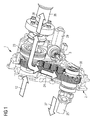
- FIG. 1 shows a perspective view of a transfer case 1.
- the total drive power 12 of an internal combustion engine of a motor vehicle, not shown, is fed to an input shaft 13.
- the input shaft 13 is in operative connection with a coupling member 23.
- the coupling member 23 is actuated by an actuator, such as a DC servo motor 29 via an actuating mechanism 3.
- the total drive power 12, or total torque, added to the input shaft 13 is divided by the coupling member 23 between the output shafts 25 and 26.
- the output side support bearing of the shaft 25 is designated in the transfer case 2.
- the power flow in the transfer case is shown in Figure 1 by the arrows 12, 27, 28.
- the arrow 12 indicates the total drive power supplied, the arrows 27 and 28, the partial drive powers for the front axle and rear axle of the four-wheel drive vehicle.
- the modulation of the power flow is performed by the DC actuator motor 29, which receives control signals from a transmission control unit, not shown, and transmits them via a gearbox mechanism 3 to the coupling member 23.
- the belt drive 24 is drawn in the embodiment shown as a positive toothed belt drive.
- the belt drive 24 can also be formed by any other traction means, such as by a chain drive or a belt body made of plastic or the like.
- FIG. 2 shows a schematic diagram of the measuring principle of the torque measuring device according to the invention.
- the drive torque M A (direction of rotation arrow 7) of the input shaft 13 is transmitted via the belt drive 24 to the output shaft 25 and calls in the drive means 24 a tensile force F k (arrow 5), which equal to the drive torque M A divided by the radius r (reference numeral 9 ) is the wrap on the output shaft 25.
- the result of this is a reaction moment (direction of rotation arrow 8) or in the drive 24 a reaction force (arrow 6)
- F r M r / r.
- the mechanical torque on the output shaft 25 is determined from the supporting force acting on the support bearing 30.
- the invention provides sensor means, which are arranged in the force flow of the supporting force between the shafts 13 and 25.
- the power flow of the support leads over the bearing of the input shaft 13 and the bearing of the output shaft 25 and via the supporting regions 32 (see FIGS. 3 to 7) of the transfer case 2 (FIG. 1).
- an elastically deformable measuring zone is formed in this way 32, in which a force transducer is arranged. This transforms the supporting force into an electrical measuring signal, which is evaluated in an evaluation unit.
- the evaluation unit contains various components, preferably digital technology, including a microprocessor 10 (FIG.
- the sensor means can be located in the path of the power flow at different locations. Three preferred measuring locations are explained in more detail below.
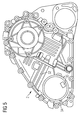
- FIG. 3 shows a first variant of the invention.
- the support bearing 30 (FIG. 1) of the output shaft 25 is designed here as a measuring bearing 31.
- the measuring bearing 31 detects the supporting force in the force-conducting region 32 between the shafts 13 and 25 (FIG. 1) which are supported in the housing 2.
- the installation space of this measuring bearing 31 is covered by the plate-shaped circuit carrier of the evaluation unit 33 (FIG. 4).
- a housing cover 34 seals the installation space.
- the housing cover 34 has a plug-in devices 35 (Fig. 5), by means of which a signal-conducting connection to a transfer case control, not shown, or to a likewise not shown stability control can be produced.
- FIG. 6 shows a second variant of the invention.
- the support bearing of the output shaft 25 (FIG. 1) is held by a bearing support ring 36, which in the path of the power flow 32 of the transfer case 2 a Strain gauge 37 carries, through which the traction means 24 (Fig. 1) caused supporting force is measured. From the measurement of this supporting force, as explained above, the mechanical torque output at the output shaft 25 is determined.
- the evaluation unit is formed by electronic components, which are housed on a plate-shaped support parallel to the bearing retainer in the housing space. The housing space is also closed here with a housing cover which has a plug-in device to the outside.
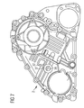
- FIG. 1 A third variant of the invention is shown in FIG.
- an elastically deformable measuring zone 38 is provided in the force-conducting region 32 between the input shaft 13 and the output shaft 25 (FIG. 1) of the transfer case 2, in which there is a force sensor, for example a suitably arranged arrangement of strain gauges 37.
- the evaluation of this measurement signal and the forwarding corresponds to the above.
Landscapes
- Engineering & Computer Science (AREA)
- General Engineering & Computer Science (AREA)
- Chemical & Material Sciences (AREA)
- Analytical Chemistry (AREA)
- Physics & Mathematics (AREA)
- General Physics & Mathematics (AREA)
- Mechanical Engineering (AREA)
- Force Measurement Appropriate To Specific Purposes (AREA)
Abstract
Description
- Die Erfindung betrifft eine Vorrichtung zur Messung des Drehmoments am Abtrieb eines Verteilergetriebes eines Kraftfahrzeugs, wobei eine Eingangswelle und eine Ausgangswelle jeweils endseitig durch Stützlager im Verteilergetriebegehäuse gelagert sind, wobei ein Umschlingungstrieb über die Eingangswelle und die Ausgangswelle geführt ist, so dass der Weg des Kraftflusses zur Abstützung der bei Betrieb auftretenden Zugkraft des Umschlingungstriebes über diese Stützlager und über kraftleitende Bereiche des Verteilergetriebegehäuses geführt ist.
- Ein Verteilergetriebe eines Kraftfahrzeuges hat die Aufgabe, die vom Motor erzeugte Gesamtantriebsleistung in zwei Teilantriebsleistungen zwischen der Vorderachse und der Hinterachse des Allradfahrzeuges aufzuteilen. Diese Aufteilung der Gesamtantriebsleistung entspricht einer variablen Momentverteilung, welche an die jeweils vorliegenden Fahrverhältnisse und an den Leistungswunsch des Fahrzeuglenkers angepasst werden muss. Zur Modulation der Momentverteilung besitzt das Verteilergetriebe eine Stellvorrichtung, die meist von einem elektromechanischen Stellantrieb betätigt wird. Der elektromechanische Stellantrieb besteht zumeist aus einem Gleichstromstellmotor, der in einer geschlossenen Regelschleife liegt. Für die elektronische Steuerung in der Regelschleife stellt das am Abtrieb des Verteilergetriebes tatsächlich abgegebene Drehmoment eine Eingangsgröße dar, die durch eine indirekte oder direkte Messmethode ermittelt werden kann.
- Eine indirekte Messmethode ist beispielsweise die Messung des Ankerstroms des Gleichstromstellmotors, aus dem dann das gesuchte Drehmoment am Abtrieb des Verteilergetriebes ermittelt wird. Hierbei taucht aber das Problem auf, dass auf Grund der sehr kurzen Stellbewegungen der Ankerstrom des Gleichstromstellmotors in erster Linie das zur Drehbeschleunigung erforderliche mechanische Moment widerspiegelt und nicht die erforderliche Stellkraft. Außerdem wird das Messergebnis durch Toleranzen der Stellmechanik und durch den Verschleiß des gesamten Verteilergetriebes verfälscht.
- Eine direkte Messmethode, wie sie beispielsweise in US 4619 6 29 für die Drehmomentmessung an einer Eingangswelle und an einer Ausgangswelle eines Automatikgetriebes vorgeschlagen wird, ist aber entsprechend aufwendig und störanfällig.
- Der Erfindung liegt die Aufgabe zu Grunde, eine Drehmomentmesseinrichtung anzugeben, mit deren Hilfe das Drehmoment am Abtrieb eines Verteilergetriebes einfach und mit hoher Funktionssicherheit erfasst werden kann und die mit vertretbarem Aufwand herstellbar ist.
- Die Lösung dieser Aufgabe erfolgt durch eine Drehmomentmesseinrichtung mit den Merkmalen des Anspruchs 1. Vorteilhafte Ausgestaltungen der Erfindung sind Gegenstand von abhängigen Ansprüchen.
- Gemäß einem Grundgedanken der vorliegenden Erfindung erfolgt die Messung des Drehmoments am Abtrieb eines Verteilergetriebes über eine Messung der Zugkraft. Erfindungsgemäß ist zur Erfassung dieser Zugkraft ein Sensormittel vorgesehen, das im Weg des Kraftflusses der Abstützkraft angeordnet ist. Das Sensormittel erzeugt am Ausgang ein elektrisches Signal, das einer Auswerteeinheit zugeführt wird. Die Auswerteeinheit besitzt ein geeignetes Rechenwerk, z.B einen Mikrorechner, so dass aus diesem Messsignal das abgegebene mechanische Moment errechnet werden kann. Ein wesentlicher Vorteil der Erfindung liegt darin, dass das Messsignal nicht von bewegten Teilen, wie beispielsweise von einer Drehmomentwelle abgenommen werden muss, sondern durch einen ortsfest angebrachten Kraftaufnehmer. Dies ermöglicht eine einfache und weitgehend störsichere Signalauswertung. Verglichen mit der indirekten Messmethode des Ankerstroms des Gleichstromstellmotors erreicht die Erfindung ein wesentlich genaueres Ergebnis. Der Kraftaufnehmer ist im Weg des Kraftflusses der Abstützung zwischen Ein- und Ausgangswelle angeordnet.
- Eine bevorzugte Ausführungsform der Erfindung sieht vor, dass das Sensormittel durch ein als Messlager ausgebildetes Stützlager der Ausgangswelle gebildet ist. Ein derartiges Messlager ist ein Wellenlager mit Kraftaufnehmer, das konstruktiv beispielsweise gemäß DE 43 13 862 C1 oder DE 36 03 187 C2 realisiert sein kann. Derartige Lager sind kommerziell verfügbar.
- Eine weitere bevorzugte Ausführungsform der Erfindung ist dadurch gekennzeichnet, dass das Sensormittel einen Dehnungsmessstreifen umfasst, der in einem Lagerhaltering des Stützlagers der Ausgangswelle angeordnet ist. Dadurch können als Stützlager handelsübliche Wälzlager verwendet werden. Eine konstruktive Ausführungsform einer derartigen Messeinheit ist beispielsweise aus DE 30 09 454 A 1 bekannt.
- Eine andere bevorzugte Ausgestaltung der Erfindung sieht vor, dass das Sensormittel in einer elastisch verformbaren Messzone, die im kraftleitenden Bereich des Verteilergetriebegehäuses ausgebildet ist, angeordnet ist. Die elastisch verformbare Messzone kann konstruktiv unterschiedlich ausgeführt sein. Sie kann z.B. aus einem Biegebalken, der durch eine Ausnehmung in der Gehäusewand gebildet ist und der mit Dehnungsmessstreifen versehen ist, bestehen.
- Besonders bevorzugt umfasst bei obigen Ausgestaltungen der Erfindung das Sensormittel einen Kraft-Messumformer, der nach einem resistiven, kapazitiven oder piezoelektrischen Messprinzip arbeitet.
- Mit Vorteil ist der Kraft-Messumformer und die Auswerteeinheit in örtlicher Nähe zur Messzone angeordnet. Aufgrund der kurzen Verbindungsleitungen und der Sinalauswertung vor Ort ist das Messergebnis weniger anfällig gegenüber elektromagnetischen Störeinflüssen.
- Konstruktiv vorteilhaft ist es, wenn die Auswerteeinheit auf einem plattenförmigen Schaltungsträger angeordnet ist, der in einem Gehäuseraum untergebracht und sich im Wesentlichen parallel und angrenzend an die Stirnfläche eines Stützlagers bzw. einer Ausnehmung im Verteilergetriebegehäuse erstreckt.
- Zum Schutz der elektronischen Bauteile und des Kraft-Sensors ist der Gehäuseraum vorteilhaft durch einen Gehäusedeckel abgeschlossen, der eine Steckvorrichtung aufweist. Dadurch kann das Messsignal über Verbindungsleitungen zwischen Schaltungsträger und Steckvorrichtung und über einen CAN-, LIN oder ähnlichen Bus einer Verteilergetriebesteuerung oder einer Stabilitätsregelung zugeführt werden.
- Für den Schaltungsträger ist je nach Temperatur und Umwelteinflüssen eine FR-4-Leiterplatte oder ein Keramiksubstrat als Werkstoff geeignet.
- Um Messfehler, die durch Vibrationen hervorgerufen werden, zu minimieren, ist ein Beschleunigungsaufnehmer vorgesehen, dessen Ausgangsignal der Mikrorechner zur Korrektur bei der Ermittlung des Drehmomentes verwendet. Dies kann beispielsweise dadurch erfolgen, dass von der gemessenen Zugkraft dieses Korrektursignal entsprechend der Größe und der Richtung addiert bzw. subtrahiert wird. Insbesondere bei starken Stößen, wie sie bei einer Geländefahrt auftreten, kann durch diese vektorielle Berücksichtigung der Beschleunigung die Drehmomentmessung mit einer besseren Genauigkeit erfolgen.
- Um Temperatureinflüsse zu kompensieren kann ein Temperatursensor vorgesehen sein, dessen Signal der Mikrorechner ebenfalls als Korrektursignal zur Driftkompensation verwendet.
- Zur weiteren Erläuterung der Erfindung wird im nachfolgenden Teil der Beschreibung auf die Zeichnungen Bezug genommen in denen weitere vorteilhafte Ausgestaltungen, Einzelheiten und Wirkungen der Erfindung zu entnehmen sind. Es zeigen:
- Figur 1
- ein Verteilergetriebe in einer geöffneten Perspektive wobei der Leistungsfluss durch Pfeile dargestellt ist;
- Figur 2
- eine schematische Darstellung des Messprinzips der erfindungsgemäßen Drehmomentmesseinrichtung;
- Figur 3
- eine erste Variante der Erfindung mit Sicht auf den Verteilergetriebegehäusedeckel bei der das Stützlager der Ausgangswelle als Messlager ausgebildet ist;
- Figur 4
- die Ausführung der Erfindung gemäß Figur 3 mit einer Auswerteeinheit, die auf einem Schaltungsträger angeordnet ist, der das Messlager abdeckt;
- Figur 5
- die Ausführung der Erfindung gemäß Figur 3, in einer Darstellung, in welcher der Aufnahmeraum für die Auswerteeinheit durch einen Gehäusedeckel dichtend verschlossen ist;
- Figur 6
- eine zweite Variante der Erfindung bei der das Sensormittel durch einen Dehnungsmessstreifen in einem Lagerhaltering eines Stützlagers der Ausgangswelle angeordnet ist;
- Figur 7
- eine dritte Variante der Erfindung, bei der das Sensormittel in einer Messzone in einem kraftleitenden Bereich zwischen der Eingangswelle und der Ausgangswelle des Verteilergetriebegehäuses angeordnet ist.
- Die Figur 1 zeigt eine perspektivische Darstellung eines Verteilergetriebes 1. Die Gesamtantriebsleistung 12 einer nicht näher dargestellten Brennkraftmaschine eines Kraftfahrzeuges wird einer Eingangswelle 13 zugeführt. Die Eingangswelle 13 steht in einer Wirkverbindung mit einem Kupplungsglied 23. Das Kupplungsglied 23 wird von einem Aktuator, beispielsweise einem Gleichstromstellmotor 29 über eine Stellmechanik 3 betätigt. Auf diese Weise wird die an der Eingangswelle 13 zugefügte Gesamtantriebsleistung 12, bzw. Gesamtmoment, durch das Kupplungsglied 23 zwischen den Ausgangswellen 25 und 26 aufgeteilt. Mit dem Bezugszeichen 30 ist das abtriebsseitige Stützlager der Welle 25 im Verteilergetriebegehäuse 2 bezeichnet. Die Kraftübertragung auf die Ausgangswelle 25 erfolgt über einen Umschlingungstrieb 24. Der Leistungsfluss im Verteilergetriebe ist in Figur 1 durch die Pfeile 12, 27, 28 dargestellt. Der Pfeil 12 kennzeichnet die zugeführte Gesamtantriebsleistung, die Pfeile 27 bzw. 28 die Teilantriebsleistungen für die Vorderachse bzw. Hinterachse des Allradfahrzeuges. Die Modulation des Leistungsflusses erfolgt durch den Gleichstromstellmotor 29, der von einer nicht näher dargestellten Getriebesteuereinheit Steuersignale erhält und diese über eine Getriebestellmechanik 3 auf das Kupplungsglied 23 überträgt. Der Umschlingungstrieb 24 ist in der gezeigten Ausführung als formschlüssiger Zahnriementrieb gezeichnet. Der Umschlingungstrieb 24 kann aber auch durch ein beliebig anderes Zugmittel, wie beispielsweise durch einen Kettentrieb oder einem Riemenkörper aus Kunststoff oder ähnlichem gebildet sein.
- In Figur 2 ist das Messprinzip der erfindungsgemäßen Drehmomentmesseinrichtung in einer Prinzipdarstellung gezeigt. Das Antriebsmoment MA (Drehrichtungspfeil 7) der Eingangswelle 13 wird über den Umschlingungstrieb 24 auf die Ausgangswelle 25 übertragen und ruft im Triebmittel 24 eine Zugkraft Fk (Pfeil 5) hervor, welche gleich dem Antriebsmoment MA dividiert durch den Radius r (Bezugszeichen 9) der Umschlingung auf der Ausgangswelle 25 ist. Folge davon ist ein Reaktionsmoment (Drehrichtungspfeil 8) bzw. im Trieb 24 eine Reaktionskraft (Pfeil 6) Fr= Mr/r. Auf das Stützlager 30 der Ausgangswelle 25 wirkt die doppelte Zugkraft (Pfeil 4), Abstützkraft FLager = Fk + Fr. Erfindungsgemäß wird das mechanische Moment an der Ausgangswelle 25 aus der auf das Stützlager 30 wirkenden Abstützkraft ermittelt. Hierzu sieht die Erfindung Sensormittel vor, die im Kraftfluss der Abstützkraft zwischen den Wellen 13 und 25 angeordnet sind. Der Kraftfluss der Abstützung führt über die Lagerung der Eingangswelle 13 und die Lagerung der Ausgangswelle 25 sowie über die tragenden Bereiche 32 (siehe Fig. 3 bis Fig. 7) des Verteilergetriebegehäuses 2 (Fig. 1). Gemäß der Erfindung ist auf diesem Weg 32 eine elastisch verformbare Messzone ausgebildet, in welcher ein Kraft-Messumformer angeordnet ist. Dieser formt die Abstützkraft in ein elektrisches Messsignal um, welches in einer Auswerteeinheit ausgewertet wird. Die Auswerteeinheit beinhaltet verschiedene Bauteile bevorzugt der Digitaltechnik darunter einen Mikroprozessor 10 (Fig. 4), der die für die Auswertung entsprechende Rechenoperationen durchführt. Bei der Berechnung des mechanischen Moments berücksichtigt er auch weitere Messsignale, die er vom einem Temperatursensor und einem Beschleunigungssensor erhält, so dass durch Temperatur oder Erschütterung verursachte Störeinflüsse durch die Berechnung kompensiert werden können.
Die Sensormittel können im Weg des Kraftflusses an verschiedenen Orten lokalisiert sein. Drei bevorzugte Messorte werden im folgenden näher erläutert. - Die Figur 3 zeigt eine erste Variante der Erfindung. Das Stützlager 30 (Fig. 1) der Ausgangswelle 25 ist hier als Messlager 31 ausgebildet. Das Messlager 31 erfasst die Abstützkraft, im kraftleitenden Bereich 32 zwischen den Wellen 13 und 25 (Fig. 1) die im Gehäuse 2 abgestützt sind. Außenseitig ist der Einbauraum dieses Messlagers 31 vom plattenförmigen Schaltungsträger der Auswerteeinheit 33 abgedeckt (Figur 4). Ein Gehäusedeckel 34 schließt den Einbauraum dichtend ab. Der Gehäusedeckel 34 weist eine Steckvorrichtungen 35 auf (Fig. 5), mittels derer eine signalleitende Verbindung zu einer nicht näher dargestellten Verteilergetriebesteuerung oder zu einer ebenfalls nicht gezeichnete Stabilitätsregelung hergestellt werden kann.
- In Figur 6 ist eine zweite Variante der Erfindung dargestellt. Das Stützlager der Ausgangswelle 25 (Fig. 1) wird von einem Lagerhaltering 36 gehalten, der im Weg des Kraftflusses 32 des Verteilergetriebes 2 einen Dehnungsmessstreifen 37 trägt, durch welchen die vom Zugmittel 24 (Fig. 1) hervorgerufene Abstützkraft gemessen wird. Aus der Messung dieser Abstützkraft wird wie oben erläutert, das an der Ausgangswelle 25 abgegebene mechanische Moment ermittelt. Auch hier wird die Auswerteeinheit durch elektronische Bauteile gebildet, die auf einem plattenförmigen Träger parallel zum Lagerhaltering im Gehäuseraum untergebracht sind. Der Gehäuseraum ist auch hier mit einem Gehäusedeckel, der nach außen eine Steckvorrichtung aufweist, verschlossen.
- Eine dritte Variante der Erfindung ist in Figur 7 dargestellt. Zur Erfassung der Abstützkraft ist im kraftleitenden Bereich 32 zwischen der Eingangswelle 13 und der Ausgangswelle 25 (Fig. 1) des Verteilergetriebegehäuses 2 mit einer elastisch verformbaren Messzone 38 versehen, in welcher sich ein Kraftsensor, beispielsweise eine geeignet angebrachte Anordnung von Dehnungsmessstreifen 37, befindet. Die Auswertung dieses Messsignals sowie die Weiterleitung entspricht dem oben Dargestellten.
-
- 1
- Verteilergetriebe
- 2
- Verteilergetriebegehäuses
- 3
- Stellmechanik zur Betätigung der Kupplung
- 4
- Abstützkraft
- 5
- Zugkraft
- 6
- Reaktionskraft
- 7
- Pfeil
- 8
- Pfeil
- 9
- Radius
- 10
- Mikroprozessor, elektronische Bauteile
- 12
- Gesamtantriebsleistung
- 13
- Eingangswelle
- 23
- Kupplungsglied
- 24
- Umschlingungstrieb
- 25
- Ausgangswelle, zur Vorderachse
- 26
- Ausgangswelle, zu Hinterachse
- 27
- Teilantriebsleistung zur Vorderachse
- 28
- Teilantriebsleistung zur Hinterachse
- 29
- Gleichstromstellmotor
- 30
- Stützlager abtriebseitig
- 31
- Messlager
- 32
- Weg des Kraftflusses, Kraftleitender Bereich von 2
- 33
- Auswerteeinheit, elektronische Schaltung
- 34
- Gehäusedeckel
- 35
- Steckvorrichtung
- 36
- Lagerhaltering
- 37
- Dehnungsmessstreifen
- 38
- elastisch verformbare Messzone
Claims (11)
- Vorrichtung zur Messung des Drehmomentes am Abtrieb eines Verteilergetriebes eines Kraftfahrzeuges, wobei eine Eingangswelle (13) und eine Ausgangswelle (25) jeweils endseitig durch Stützlager (30) im Verteilergetriebegehäuse (2) gelagert sind, wobei ein Umschlingungstrieb (24) über die Eingangswelle (13) und die Ausgangswelle (25) geführt ist, so dass der Weg des Kraftflusses zur Abstützung der bei Betrieb auftretenden Zugkraft des Umschlingungstriebes über diese Stützlager und über kraftleitende Bereiche (32) des Verteilergetriebegehäuses geführt ist, dadurch gekennzeichnet, dass die Zugkraft durch Sensormittel (31, 36, 37, 38) erfasst wird, die im weg des Kraftflusses angeordnet sind und ein Ausgangssignal erzeugen, das einer Auswerteeinheit (33) zugeführt ist.
- Vorrichtung nach Anspruch 1, dadurch gekennzeichnet, dass das Sensormittel durch ein als Messlager (31) ausgebildetes Stützlager der Ausgangswelle gebildet ist.
- Vorrichtung nach Anspruch 1, dadurch gekennzeichnet, dass das Sensormittel einen Dehnungsmessstreifen (37) umfasst, der in einem Lagerhaltering (36) des Stützlagers der Ausgangswelle angeordnet ist.
- Vorrichtung nach Anspruch 1, dadurch gekennzeichnet, dass das Sensormittel in einer elastisch verformbaren Messzone (38), die durch eine Ausnehmung im kraftleitenden Bereich des Verteilergetriebegehäuses ausgebildet ist, angeordnet ist.
- Vorrichtung nach einem der Ansprüche 2, 3 oder 4, dadurch gekennzeichnet, dass das Sensormittel einen resistiven, kapazitiven oder piezoelektrischen Kraft-Messumformer umfasst.
- Vorrichtung nach Anspruch 5, dadurch gekennzeichnet dass der Kraft-Messumformer mit einer elektronischen Schaltung auf einem plattenförmigen Schaltungsträger verbunden ist.
- Vorrichtung nach Anspruch 6, dadurch gekennzeichnet, dass der Schaltungsträger in einem Gehäuseraum untergebracht ist und sich im Wesentlichen parallel und angrenzend an die Stirnfläche eines Stützlagers bzw. der Ausnehmung erstreckt.
- Vorrichtung nach Anspruch 7, dadurch gekennzeichnet, dass der Gehäuseraum durch einen Gehäusedeckel (34) abgeschlossen ist, der eine Steckvorrichtung 35) aufweist welche über Verbindungsleitungen mit dem Schaltungsträger verbunden ist.
- Vorrichtung nach einem der Ansprüche 6 bis 8, dadurch gekennzeichnet, dass für den Schaltungsträger eine FR 4-Leiterplatte oder ein Keramiksubstrat verwendet wird.
- Vorrichtung nach einem der vorstehenden Ansprüche, dadurch gekennzeichnet, dass die Auswerteeinheit einen Mikroprozessor (10) enthält, dem das Messsignal des Sensormittels und zumindest ein weiteres Messsignal eines zumindest weiteren Sensormittels zugeführt ist, und dass der Mikroprozessor bei der Berechnung des Drehmoments das zumindest eine weitere Messsignal dazu verwendet, um Fehlereinflüsse, die durch Vibrationen und Temperaturschwankungen verursacht werden, zu berücksichtigen.
- Vorrichtung nach Anspruch 10, dadurch gekennzeichnet, dass der vom Mikrorechner (10) ermittelt Wert des Drehmoments über die Steckvorrichtung und einem CAN-, einem LIN- oder einem ähnlichen Bus an eine Verteilergetriebesteuerung oder eine Stabilitätsregelung übermittelt wird.
Applications Claiming Priority (1)
| Application Number | Priority Date | Filing Date | Title |
|---|---|---|---|
| AT0062904U AT8410U1 (de) | 2004-08-26 | 2004-08-26 | Vorrichtung zur messung des drehmoments am abtrieb eines verteilergetriebes eines kraftfahrzeuges |
Publications (2)
| Publication Number | Publication Date |
|---|---|
| EP1630029A1 true EP1630029A1 (de) | 2006-03-01 |
| EP1630029B1 EP1630029B1 (de) | 2011-10-05 |
Family
ID=44741038
Family Applications (1)
| Application Number | Title | Priority Date | Filing Date |
|---|---|---|---|
| EP05103682A Expired - Lifetime EP1630029B1 (de) | 2004-08-26 | 2005-05-03 | Vorrichtung zur Messung des Drehmoments am Abtrieb eines Verteilergetriebes eines Kraftfahrzeuges |
Country Status (2)
| Country | Link |
|---|---|
| EP (1) | EP1630029B1 (de) |
| AT (2) | AT8410U1 (de) |
Families Citing this family (1)
| Publication number | Priority date | Publication date | Assignee | Title |
|---|---|---|---|---|
| DE102010024806B4 (de) * | 2010-06-23 | 2014-03-13 | Deutsches Zentrum für Luft- und Raumfahrt e.V. | Drehmoment-Messeinrichtung und Verfahren zur Drehmomentmessung |
Citations (2)
| Publication number | Priority date | Publication date | Assignee | Title |
|---|---|---|---|---|
| US4619629A (en) | 1984-05-03 | 1986-10-28 | Toyota Jidosha Kabushiki Kaisha | Hydraulic pressure control apparatus for a continuously variable transmission |
| US5992243A (en) | 1996-12-21 | 1999-11-30 | Dana Corporation | Four-wheel drive transfer case with torque sensing |
Family Cites Families (5)
| Publication number | Priority date | Publication date | Assignee | Title |
|---|---|---|---|---|
| DE3009454A1 (de) * | 1980-03-12 | 1981-09-24 | Fried. Krupp Gmbh, 4300 Essen | Messeinheit zur ermittlung der belastung von wellen |
| DE3603187A1 (de) * | 1986-02-03 | 1987-08-06 | Erhardt & Leimer Gmbh | Vorrichtung zur linearkraftmessung |
| DE4313862C1 (de) * | 1993-04-28 | 1994-07-28 | Hottinger Messtechnik Baldwin | Wellenlagerung mit Kraftaufnehmer |
| JP3427529B2 (ja) * | 1994-12-26 | 2003-07-22 | 日産自動車株式会社 | 四輪駆動車の駆動力分配制御装置 |
| US6490935B1 (en) * | 1999-09-28 | 2002-12-10 | The Timken Company | System for monitoring the operating conditions of a bearing |
-
2004
- 2004-08-26 AT AT0062904U patent/AT8410U1/de not_active IP Right Cessation
-
2005
- 2005-05-03 EP EP05103682A patent/EP1630029B1/de not_active Expired - Lifetime
- 2005-05-03 AT AT05103682T patent/ATE527132T1/de active
Patent Citations (2)
| Publication number | Priority date | Publication date | Assignee | Title |
|---|---|---|---|---|
| US4619629A (en) | 1984-05-03 | 1986-10-28 | Toyota Jidosha Kabushiki Kaisha | Hydraulic pressure control apparatus for a continuously variable transmission |
| US5992243A (en) | 1996-12-21 | 1999-11-30 | Dana Corporation | Four-wheel drive transfer case with torque sensing |
Also Published As
| Publication number | Publication date |
|---|---|
| AT8410U1 (de) | 2006-07-15 |
| ATE527132T1 (de) | 2011-10-15 |
| EP1630029B1 (de) | 2011-10-05 |
Similar Documents
| Publication | Publication Date | Title |
|---|---|---|
| DE102014009746A1 (de) | Anhänger für ein Fahrrad | |
| DE102021201229A1 (de) | Feedback-Aktuator und Steer-by-wire-Lenksystem für ein Kraftfahrzeug | |
| DE102015224337A1 (de) | Elektrisches Antriebssystem | |
| DE19811869A1 (de) | Vorrichtung zur elektronischen Steuerung eines Drosselventils in einem Motor mit innerer Verbrennung | |
| EP1503196B1 (de) | Verfahren und Einrichtung zum Messen des Abtriebsdrehmoments eines Elektromotors mit einem diesem nachgeordneten Getriebe | |
| DE3842037A1 (de) | Einrichtung zur erfassung einer axialkraft einer deichselkupplung | |
| DE2554519C3 (de) | Antriebsvorrichtung für einen Rotor | |
| DE102005018708B4 (de) | Wägevorrichtung, insbesondere Mehrspur-Wägevorrichtung | |
| EP1630029B1 (de) | Vorrichtung zur Messung des Drehmoments am Abtrieb eines Verteilergetriebes eines Kraftfahrzeuges | |
| DE102019216027A1 (de) | Dehnungsdrehmoment-messsystem | |
| DE102017125584A1 (de) | Verfahren zur Filterung eines Wegsignals eines Wegsensors einer Kupplungs-betätigungsvorrichtung | |
| EP4026753B1 (de) | Verfahren zur bestimmung des verschleisses eines lenksystems eines fahrzeugs | |
| DE102017110165B3 (de) | Verfahren zur Ansteuerung einer Kupplung mit einem Kupplungsbetätigungssystem und ein Kupplungsbetätigungssystem | |
| DE19756239A1 (de) | Vorgelege für Vierradantrieb | |
| DE202009006490U1 (de) | Abgasturbolader | |
| DE102011000331A1 (de) | Verfahren und Vorrichtung zur Bestimmung eines auf eine Antriebswelle eines Kraftfahrzeugs wirkenden Drehmoments | |
| EP2715191B1 (de) | Vorrichtung zum überwachen eines schmierölkreislaufs eines automatisierten fahrzeuggetriebes | |
| DE102004041733B4 (de) | Vorrichtung und Verfahren zur Erfassung von Kraft und Weg an einem Pedalwerk | |
| DE102019100323A1 (de) | Diagnose eines Verdrehspiels im Antriebsstrang | |
| DE19754523A1 (de) | Anordnung zur Ermittlung des Verschleißes einer Fahrzeugkupplung | |
| DE102006037958A1 (de) | Kupplungseinrichtung | |
| DE102020133576A1 (de) | Lenkanordnung und Fahrzeug sowie Verfahren zum Bestimmen eines Lenkmomentes einer Lenkung | |
| DE102023100473B3 (de) | Lagereinheit mit integriertem Sensor | |
| DE102004059081A1 (de) | Kraftsensor zur Bremskraftbestimmung an einer Reibbremse für rotierende Körper | |
| DE102015208225A1 (de) | Absolutwegmesseinrichtung für einen Spindelaktor einer hydraulischen Gebereinheit und Verfahren zum Bestimmen einer Winkelstellung eines zweiten Messmagenten einer Absolutwegmesseinrichtung |
Legal Events
| Date | Code | Title | Description |
|---|---|---|---|
| PUAI | Public reference made under article 153(3) epc to a published international application that has entered the european phase |
Free format text: ORIGINAL CODE: 0009012 |
|
| AK | Designated contracting states |
Kind code of ref document: A1 Designated state(s): AT BE BG CH CY CZ DE DK EE ES FI FR GB GR HU IE IS IT LI LT LU MC NL PL PT RO SE SI SK TR |
|
| AX | Request for extension of the european patent |
Extension state: AL BA HR LV MK YU |
|
| 17P | Request for examination filed |
Effective date: 20060831 |
|
| AKX | Designation fees paid |
Designated state(s): AT BE BG CH CY CZ DE DK EE ES FI FR GB GR HU IE IS IT LI LT LU MC NL PL PT RO SE SI SK TR |
|
| 17Q | First examination report despatched |
Effective date: 20100518 |
|
| RAP1 | Party data changed (applicant data changed or rights of an application transferred) |
Owner name: MELECS EWS GMBH & CO KG |
|
| GRAP | Despatch of communication of intention to grant a patent |
Free format text: ORIGINAL CODE: EPIDOSNIGR1 |
|
| GRAS | Grant fee paid |
Free format text: ORIGINAL CODE: EPIDOSNIGR3 |
|
| GRAA | (expected) grant |
Free format text: ORIGINAL CODE: 0009210 |
|
| AK | Designated contracting states |
Kind code of ref document: B1 Designated state(s): AT BE BG CH CY CZ DE DK EE ES FI FR GB GR HU IE IS IT LI LT LU MC NL PL PT RO SE SI SK TR |
|
| REG | Reference to a national code |
Ref country code: GB Ref legal event code: FG4D Free format text: NOT ENGLISH |
|
| REG | Reference to a national code |
Ref country code: CH Ref legal event code: EP |
|
| REG | Reference to a national code |
Ref country code: IE Ref legal event code: FG4D |
|
| REG | Reference to a national code |
Ref country code: DE Ref legal event code: R096 Ref document number: 502005011959 Country of ref document: DE Effective date: 20111201 |
|
| REG | Reference to a national code |
Ref country code: NL Ref legal event code: VDEP Effective date: 20111005 |
|
| PG25 | Lapsed in a contracting state [announced via postgrant information from national office to epo] |
Ref country code: SI Free format text: LAPSE BECAUSE OF FAILURE TO SUBMIT A TRANSLATION OF THE DESCRIPTION OR TO PAY THE FEE WITHIN THE PRESCRIBED TIME-LIMIT Effective date: 20111005 |
|
| LTIE | Lt: invalidation of european patent or patent extension |
Effective date: 20111005 |
|
| PG25 | Lapsed in a contracting state [announced via postgrant information from national office to epo] |
Ref country code: IS Free format text: LAPSE BECAUSE OF FAILURE TO SUBMIT A TRANSLATION OF THE DESCRIPTION OR TO PAY THE FEE WITHIN THE PRESCRIBED TIME-LIMIT Effective date: 20120205 Ref country code: LT Free format text: LAPSE BECAUSE OF FAILURE TO SUBMIT A TRANSLATION OF THE DESCRIPTION OR TO PAY THE FEE WITHIN THE PRESCRIBED TIME-LIMIT Effective date: 20111005 |
|
| REG | Reference to a national code |
Ref country code: IE Ref legal event code: FD4D |
|
| PG25 | Lapsed in a contracting state [announced via postgrant information from national office to epo] |
Ref country code: NL Free format text: LAPSE BECAUSE OF FAILURE TO SUBMIT A TRANSLATION OF THE DESCRIPTION OR TO PAY THE FEE WITHIN THE PRESCRIBED TIME-LIMIT Effective date: 20111005 Ref country code: SE Free format text: LAPSE BECAUSE OF FAILURE TO SUBMIT A TRANSLATION OF THE DESCRIPTION OR TO PAY THE FEE WITHIN THE PRESCRIBED TIME-LIMIT Effective date: 20111005 Ref country code: GR Free format text: LAPSE BECAUSE OF FAILURE TO SUBMIT A TRANSLATION OF THE DESCRIPTION OR TO PAY THE FEE WITHIN THE PRESCRIBED TIME-LIMIT Effective date: 20120106 Ref country code: PT Free format text: LAPSE BECAUSE OF FAILURE TO SUBMIT A TRANSLATION OF THE DESCRIPTION OR TO PAY THE FEE WITHIN THE PRESCRIBED TIME-LIMIT Effective date: 20120206 |
|
| PG25 | Lapsed in a contracting state [announced via postgrant information from national office to epo] |
Ref country code: CY Free format text: LAPSE BECAUSE OF FAILURE TO SUBMIT A TRANSLATION OF THE DESCRIPTION OR TO PAY THE FEE WITHIN THE PRESCRIBED TIME-LIMIT Effective date: 20111005 |
|
| PG25 | Lapsed in a contracting state [announced via postgrant information from national office to epo] |
Ref country code: CZ Free format text: LAPSE BECAUSE OF FAILURE TO SUBMIT A TRANSLATION OF THE DESCRIPTION OR TO PAY THE FEE WITHIN THE PRESCRIBED TIME-LIMIT Effective date: 20111005 Ref country code: SK Free format text: LAPSE BECAUSE OF FAILURE TO SUBMIT A TRANSLATION OF THE DESCRIPTION OR TO PAY THE FEE WITHIN THE PRESCRIBED TIME-LIMIT Effective date: 20111005 Ref country code: BG Free format text: LAPSE BECAUSE OF FAILURE TO SUBMIT A TRANSLATION OF THE DESCRIPTION OR TO PAY THE FEE WITHIN THE PRESCRIBED TIME-LIMIT Effective date: 20120105 Ref country code: DK Free format text: LAPSE BECAUSE OF FAILURE TO SUBMIT A TRANSLATION OF THE DESCRIPTION OR TO PAY THE FEE WITHIN THE PRESCRIBED TIME-LIMIT Effective date: 20111005 Ref country code: EE Free format text: LAPSE BECAUSE OF FAILURE TO SUBMIT A TRANSLATION OF THE DESCRIPTION OR TO PAY THE FEE WITHIN THE PRESCRIBED TIME-LIMIT Effective date: 20111005 Ref country code: IE Free format text: LAPSE BECAUSE OF FAILURE TO SUBMIT A TRANSLATION OF THE DESCRIPTION OR TO PAY THE FEE WITHIN THE PRESCRIBED TIME-LIMIT Effective date: 20111005 |
|
| PLBE | No opposition filed within time limit |
Free format text: ORIGINAL CODE: 0009261 |
|
| STAA | Information on the status of an ep patent application or granted ep patent |
Free format text: STATUS: NO OPPOSITION FILED WITHIN TIME LIMIT |
|
| PG25 | Lapsed in a contracting state [announced via postgrant information from national office to epo] |
Ref country code: RO Free format text: LAPSE BECAUSE OF FAILURE TO SUBMIT A TRANSLATION OF THE DESCRIPTION OR TO PAY THE FEE WITHIN THE PRESCRIBED TIME-LIMIT Effective date: 20111005 Ref country code: IT Free format text: LAPSE BECAUSE OF FAILURE TO SUBMIT A TRANSLATION OF THE DESCRIPTION OR TO PAY THE FEE WITHIN THE PRESCRIBED TIME-LIMIT Effective date: 20111005 Ref country code: PL Free format text: LAPSE BECAUSE OF FAILURE TO SUBMIT A TRANSLATION OF THE DESCRIPTION OR TO PAY THE FEE WITHIN THE PRESCRIBED TIME-LIMIT Effective date: 20111005 |
|
| 26N | No opposition filed |
Effective date: 20120706 |
|
| REG | Reference to a national code |
Ref country code: DE Ref legal event code: R097 Ref document number: 502005011959 Country of ref document: DE Effective date: 20120706 |
|
| BERE | Be: lapsed |
Owner name: MELECS EWS GMBH & CO KG Effective date: 20120531 |
|
| PG25 | Lapsed in a contracting state [announced via postgrant information from national office to epo] |
Ref country code: MC Free format text: LAPSE BECAUSE OF NON-PAYMENT OF DUE FEES Effective date: 20120531 |
|
| PGFP | Annual fee paid to national office [announced via postgrant information from national office to epo] |
Ref country code: DE Payment date: 20120720 Year of fee payment: 8 |
|
| REG | Reference to a national code |
Ref country code: CH Ref legal event code: PL |
|
| GBPC | Gb: european patent ceased through non-payment of renewal fee |
Effective date: 20120503 |
|
| PG25 | Lapsed in a contracting state [announced via postgrant information from national office to epo] |
Ref country code: LI Free format text: LAPSE BECAUSE OF NON-PAYMENT OF DUE FEES Effective date: 20120531 Ref country code: CH Free format text: LAPSE BECAUSE OF NON-PAYMENT OF DUE FEES Effective date: 20120531 |
|
| PG25 | Lapsed in a contracting state [announced via postgrant information from national office to epo] |
Ref country code: BE Free format text: LAPSE BECAUSE OF NON-PAYMENT OF DUE FEES Effective date: 20120531 |
|
| REG | Reference to a national code |
Ref country code: FR Ref legal event code: ST Effective date: 20130131 |
|
| PG25 | Lapsed in a contracting state [announced via postgrant information from national office to epo] |
Ref country code: GB Free format text: LAPSE BECAUSE OF NON-PAYMENT OF DUE FEES Effective date: 20120503 Ref country code: FR Free format text: LAPSE BECAUSE OF NON-PAYMENT OF DUE FEES Effective date: 20120531 Ref country code: ES Free format text: LAPSE BECAUSE OF FAILURE TO SUBMIT A TRANSLATION OF THE DESCRIPTION OR TO PAY THE FEE WITHIN THE PRESCRIBED TIME-LIMIT Effective date: 20120116 |
|
| PG25 | Lapsed in a contracting state [announced via postgrant information from national office to epo] |
Ref country code: FI Free format text: LAPSE BECAUSE OF FAILURE TO SUBMIT A TRANSLATION OF THE DESCRIPTION OR TO PAY THE FEE WITHIN THE PRESCRIBED TIME-LIMIT Effective date: 20111005 |
|
| REG | Reference to a national code |
Ref country code: AT Ref legal event code: MM01 Ref document number: 527132 Country of ref document: AT Kind code of ref document: T Effective date: 20120503 |
|
| PG25 | Lapsed in a contracting state [announced via postgrant information from national office to epo] |
Ref country code: AT Free format text: LAPSE BECAUSE OF NON-PAYMENT OF DUE FEES Effective date: 20120503 |
|
| PG25 | Lapsed in a contracting state [announced via postgrant information from national office to epo] |
Ref country code: DE Free format text: LAPSE BECAUSE OF NON-PAYMENT OF DUE FEES Effective date: 20131203 |
|
| REG | Reference to a national code |
Ref country code: DE Ref legal event code: R119 Ref document number: 502005011959 Country of ref document: DE Effective date: 20131203 |
|
| PG25 | Lapsed in a contracting state [announced via postgrant information from national office to epo] |
Ref country code: TR Free format text: LAPSE BECAUSE OF FAILURE TO SUBMIT A TRANSLATION OF THE DESCRIPTION OR TO PAY THE FEE WITHIN THE PRESCRIBED TIME-LIMIT Effective date: 20111005 |
|
| PG25 | Lapsed in a contracting state [announced via postgrant information from national office to epo] |
Ref country code: LU Free format text: LAPSE BECAUSE OF NON-PAYMENT OF DUE FEES Effective date: 20120503 |
|
| PG25 | Lapsed in a contracting state [announced via postgrant information from national office to epo] |
Ref country code: HU Free format text: LAPSE BECAUSE OF FAILURE TO SUBMIT A TRANSLATION OF THE DESCRIPTION OR TO PAY THE FEE WITHIN THE PRESCRIBED TIME-LIMIT Effective date: 20050503 |