EP1629761A2 - Dust collection unit and vacuum cleaner comprising same - Google Patents
Dust collection unit and vacuum cleaner comprising same Download PDFInfo
- Publication number
- EP1629761A2 EP1629761A2 EP05107844A EP05107844A EP1629761A2 EP 1629761 A2 EP1629761 A2 EP 1629761A2 EP 05107844 A EP05107844 A EP 05107844A EP 05107844 A EP05107844 A EP 05107844A EP 1629761 A2 EP1629761 A2 EP 1629761A2
- Authority
- EP
- European Patent Office
- Prior art keywords
- dust collection
- filter
- unit
- collection unit
- unit according
- Prior art date
- Legal status (The legal status is an assumption and is not a legal conclusion. Google has not performed a legal analysis and makes no representation as to the accuracy of the status listed.)
- Granted
Links
- 239000000428 dust Substances 0.000 title claims abstract description 81
- 238000004140 cleaning Methods 0.000 claims abstract description 64
- 238000001914 filtration Methods 0.000 claims description 6
- 239000013013 elastic material Substances 0.000 claims description 2
- 239000002245 particle Substances 0.000 description 9
- 238000000926 separation method Methods 0.000 description 7
- 230000004048 modification Effects 0.000 description 2
- 238000012986 modification Methods 0.000 description 2
- 239000000853 adhesive Substances 0.000 description 1
- 230000001070 adhesive effect Effects 0.000 description 1
- 230000002238 attenuated effect Effects 0.000 description 1
- 230000001680 brushing effect Effects 0.000 description 1
- 230000000994 depressogenic effect Effects 0.000 description 1
- 230000006866 deterioration Effects 0.000 description 1
- 239000000463 material Substances 0.000 description 1
Images


Classifications
-
- A—HUMAN NECESSITIES
- A47—FURNITURE; DOMESTIC ARTICLES OR APPLIANCES; COFFEE MILLS; SPICE MILLS; SUCTION CLEANERS IN GENERAL
- A47L—DOMESTIC WASHING OR CLEANING; SUCTION CLEANERS IN GENERAL
- A47L9/00—Details or accessories of suction cleaners, e.g. mechanical means for controlling the suction or for effecting pulsating action; Storing devices specially adapted to suction cleaners or parts thereof; Carrying-vehicles specially adapted for suction cleaners
- A47L9/0081—Means for exhaust-air diffusion; Means for sound or vibration damping
-
- A—HUMAN NECESSITIES
- A47—FURNITURE; DOMESTIC ARTICLES OR APPLIANCES; COFFEE MILLS; SPICE MILLS; SUCTION CLEANERS IN GENERAL
- A47L—DOMESTIC WASHING OR CLEANING; SUCTION CLEANERS IN GENERAL
- A47L9/00—Details or accessories of suction cleaners, e.g. mechanical means for controlling the suction or for effecting pulsating action; Storing devices specially adapted to suction cleaners or parts thereof; Carrying-vehicles specially adapted for suction cleaners
- A47L9/20—Means for cleaning filters
-
- Y—GENERAL TAGGING OF NEW TECHNOLOGICAL DEVELOPMENTS; GENERAL TAGGING OF CROSS-SECTIONAL TECHNOLOGIES SPANNING OVER SEVERAL SECTIONS OF THE IPC; TECHNICAL SUBJECTS COVERED BY FORMER USPC CROSS-REFERENCE ART COLLECTIONS [XRACs] AND DIGESTS
- Y10—TECHNICAL SUBJECTS COVERED BY FORMER USPC
- Y10S—TECHNICAL SUBJECTS COVERED BY FORMER USPC CROSS-REFERENCE ART COLLECTIONS [XRACs] AND DIGESTS
- Y10S55/00—Gas separation
- Y10S55/02—Vacuum cleaner bags
-
- Y—GENERAL TAGGING OF NEW TECHNOLOGICAL DEVELOPMENTS; GENERAL TAGGING OF CROSS-SECTIONAL TECHNOLOGIES SPANNING OVER SEVERAL SECTIONS OF THE IPC; TECHNICAL SUBJECTS COVERED BY FORMER USPC CROSS-REFERENCE ART COLLECTIONS [XRACs] AND DIGESTS
- Y10—TECHNICAL SUBJECTS COVERED BY FORMER USPC
- Y10S—TECHNICAL SUBJECTS COVERED BY FORMER USPC CROSS-REFERENCE ART COLLECTIONS [XRACs] AND DIGESTS
- Y10S55/00—Gas separation
- Y10S55/03—Vacuum cleaner
Definitions
- a filtering unit is provided on an inner surface of the dust collection container to filter off dirt particles among the foreign objects sucked into the dust collection container.
- the filter unit is classified into a cyclone type separating foreign objects having heavy self-weight in cyclone airflow and a porous filter type for filtering off foreign objects greater than a predetermined volume while air containing the foreign objects passes through a porous filter.
- both of these two types of filter units are generally provided in the dust collection unit. That is, the porous type filter unit is installed in the cyclone type filter unit. Therefore, the relatively large-sized foreign objects are first filtered off by the cyclone type filter unit and the relatively small-sized foreign objects are secondary filtered off by the porous type filter unit.
- the outer filter 150b is provided at a top with a plurality of fixing projections 154 for fixing the porous filter unit 150 on the top cover 120.
- the fixing projections 154 are coupled to the inner bottom of the top cover 120, the outer filter 150b is fixed on the inner bottom of the top cover 120 in a state where the inner filter 150a is received in the outer filter 150b so that the porous filter unit 150 can filter the foreign objects in the dust collection container 110.
- each of the top and bottom rotation guides 162a and 162b is greater than the outer diameter of the outer filter 150b so that no interference between the filter-cleaning unit 160 and the outer filter 150b is incurred during the outer cleaning unit 160 rotates around the outer filter 150b.
- a plurality of connecting projections 163 are provided on outer circumferences of the rotation guides 162a and 162b.
- the connecting projections 163 are designed having a size that can allow a brush support unit 164 (see FIG. 2) to interconnect the top and bottom rotation guides 162a and 162b in a state where the brush support unit 164 is spaced away from the outer circumference of the outer filter 150b.
- a noise-preventing pad 170 having a predetermined thickness is formed on a top surface of the top rotation guide 162a between the top of the filter-cleaning unit 160 and the outer filter 150b.
- the noise-preventing pad 170 includes an attaching member 172 attached on the top surface of the top rotation guide 162a and a contacting member 174 formed on the attaching member 172 to sliding-contact a surface of the outer filter 150b when the filter-cleaning unit 160.
- the attaching and contacting members 172 and 174 may be formed of elastic material so that they can be restored to their initial shapes even when the filter-cleaning unit 160 contacts the bottom of the fixing projections 154, thereby reducing the friction and noise. Furthermore, in order to reduce the friction, the contacting surface 174 is slippery processed.
- the operation of the filter-cleaning unit 160 for removing the foreign object clogging the outer circumference of the outer filter 150b will be described with reference to FIG. 1.
Abstract
Description
- The present invention relates to a vacuum cleaner, and particularly, to a dust collection unit for a vacuum cleaner, which can automatically remove foreign objects clogging the filter unit. More particularly, the present invention relates to a dust collection unit for a vacuum cleaner, which can efficiently remove foreign objects adhered to a surface of a porous filter unit while air passes through the dust collection unit and reduce noise generated during the cleaning of the porous filter unit.
- A vacuum cleanser is classified into a canister type and an upright type. The former includes a suction nozzle unit sucking air containing foreign object while moving along a floor, a main body with a unit for generating air suctioning force through the suction nozzle unit, a dust collection unit for filtering foreign object contained in the air sucked into the main body, and an operating unit mounted on the main body so that a user grasps the operating unit in use. The suction nozzle unit, the main body, the dust collection unit, and the operating unit are integrated in a single body. The latter includes a suction nozzle unit and a main body receiving a dust collection unit. The suction nozzle unit and the main body are provided in separated units. A flexible hose is provided to interconnect the suction unit and the main body. Therefore, the cleaning is performed while moving the suction nozzle unit in a state where the main body is fixed at a location.
- That is, the dust collection unit includes a cylindrical dust collection container and upper and lower covers that defines a top and bottom of the dust collection container, respectively. A suction guide is formed on a portion of the dust collection container to suck outer air and an outlet guide is provided on another portion of the dust collection container to exhaust the air from which foreign objects are removed.
- In addition, a filtering unit is provided on an inner surface of the dust collection container to filter off dirt particles among the foreign objects sucked into the dust collection container. The filter unit is classified into a cyclone type separating foreign objects having heavy self-weight in cyclone airflow and a porous filter type for filtering off foreign objects greater than a predetermined volume while air containing the foreign objects passes through a porous filter. In order to improve the foreign object removal efficiency, both of these two types of filter units are generally provided in the dust collection unit. That is, the porous type filter unit is installed in the cyclone type filter unit. Therefore, the relatively large-sized foreign objects are first filtered off by the cyclone type filter unit and the relatively small-sized foreign objects are secondary filtered off by the porous type filter unit.
- The constitution and operation of the filter unit will be described in more detail hereinafter.
- The cyclone type filter unit is provided in the dust collection container and the porous type filter unit is installed in the cyclone type filter unit. When the air is introduced into the dust collection unit, the air flows in cyclone pattern in the cyclone type filter unit. At this point, the foreign objects heavier than the air fall down to be stored a separated foreign object-storing chamber. The foreign objects that are not removed by the cyclone type filter unit are filtered off by the porous filter unit while the air passes through the porous filter unit.
- At this point, dirt particles may clog the surface of the porous filter unit. When the amount of the dirt particles clogging the surface of the porous filter unit is increased, airflow resistance is increased to deteriorate the air suctioning force. Furthermore, the motor may be overloaded. When the dirt particles are tightly adhered to the surface of the porous filter unit, it is difficult to remove the same from the porous filter even when the cleaning operation is performed.
- Accordingly, the present invention is directed to a dust collection unit and a vacuum cleaner with the same that substantially obviates one or more problems due to limitations and disadvantages of the related art.
- An object of the present invention is to provide a dust collection unit of a vacuum cleaner, which can improve the dust removal efficiency and prevent the overload of a motor by providing a filter-cleaning unit on an outer surface of a filter unit for filtering off foreign objects contained in air introduced into a main body of the vacuum cleaner.
- Another object of the present invention is to provide a dust collection unit of a vacuum cleaner, which can enhance cleaning efficiency of a filter-cleaning unit provided on an outer surface of a filter unit.
- Still another object of the present invention is to provide a dust collection unit of a vacuum cleaner, which can attenuate noise generated during the operation of a filter-cleaning unit, thereby reducing unpleasant feeling of a user.
- Still yet another object of the present invention is to provide a dust collection unit of a vacuum cleaner, which can improve dust collection efficiency and prevent the overload of a motor by preventing foreign object from excessively clogging an outer surface of the porous filter unit.
- Additional advantages, objects, and features of the invention will be set forth in part in the description which follows and in part will become apparent to those having ordinary skill in the art upon examination of the following or may be learned from practice of the invention. The objectives and other advantages of the invention may be realized and attained by the structure particularly pointed out in the written description and claims hereof as well as the appended drawings.
- To achieve these objects and other advantages and in accordance with the purpose of the invention, as embodied and broadly described herein, there is provided a dust collection unit for a vacuum cleaner, including: a dust collection container for collecting foreign objects contained in air introduced therein; covers defining a top and bottom of the dust collection container; and a filter-cleaning unit having a plurality of brushes rotating around the porous filter unit to remove the foreign objects clogging the outer surface of the porous filter unit.
- According to another aspect of the present invention, there is provided a dust collection for a vacuum cleaner, including: a dust collection container for collecting foreign objects contained in air introduced therein; a porous filter unit for filtering off the foreign objects in the dust collection container; and a filter-cleaning unit for removing the foreign objects clogging an outer surface of the porous filter unit by rotating around the porous filter unit, wherein the filter-cleaning unit comprises rotation guides formed on a top and bottom of the porous filter unit; a plurality of brush supports interconnecting the rotation guides; a plurality of brushes attached on inner surfaces of the brush supports; and blades alternatively disposed with the rotation guides and connected to the rotation guides.
- According to still another aspect of the present invention, there is provided a dust collection unit for a vacuum cleaner, including: a dust collection container for collecting foreign objects contained in air introduced therein; covers defining a top and bottom of the dust collection container; a filter-cleaning unit having a plurality of brushes rotating around the porous filter unit to remove the foreign objects clogging the outer surface of the porous filter unit; and a noise-preventing pad formed between the filter-cleaning unit and the porous filter unit.
- According to the present invention, since the foreign objects clogging the outer surface of the porous filter unit can be effectively removed, the air effectively flows, thereby improving the dust removal efficiency of the vacuum cleaner and preventing the overload of the motor.
- In addition, since the noise that may be caused by a collision between components during the operation of the filter-cleaning unit is attenuated, the pleasant feeling can be provided for the user.
- The accompanying drawings, which are included to provide a further understanding of the invention and are incorporated in and constitute a part of this application, illustrate embodiment(s) of the invention and together with the description serve to explain the principle of the invention. In the drawings:
- FIG. 1 is an exploded perspective view of a dust collection unit of a vacuum cleaner according to an embodiment of the present invention;
- FIG. 2 is an exploded perspective view of a porous filter unit depicted in FIG. 1; and
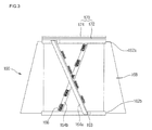
- FIG. 3 is a perspective view of a filter-cleaning unit depicted in FIG. 2.
- Reference will now be made in detail to the preferred embodiments of the present invention, examples of which are illustrated in the accompanying drawings. Wherever possible, the same reference numbers will be used throughout the drawings to refer to the same or like parts.
- FIG. 1 shows a dust collection unit according to an embodiment of the present invention.
- Referring to FIG. 1, the inventive vacuum cleaner includes a
dust collection container 110 and upper andlower cover 120 defining a top and bottom of thedust collection container 110. Asuction guide 112 is provided on a portion of an outer circumference of thedust collection container 110. The suction guide extends from the outer circumference of thedust collection container 110 to guide the air into thedust collection container 110 along an inner wall of thedust collection container 110 in a tangential direction. In addition, thesuction guide 112 extends along an outer surface tangential line of thedust collection container 110. Therefore, cyclone airflow is generated in thedust collection container 110. - In addition, a
handle 114 is formed on a portion of the outer circumference of thedust collection container 110, which is opposite to the portion where thesuction guide 112 is formed. A bottom of thehandle 114 is depressed upward so that the user can move thedust collection unit 100 using thehandle 114. - In addition, a
separation plate 140 is provided in thedust collection container 110 to divide an inner space of thedust collection container 110 into upper and lower chambers. Theseparation plate 140 is provided at an edge with a droppingportion 142 communicating the upper chamber with the lower chamber. The upper chamber functions as a foreign object removal chamber while the lower chamber functions as a foreign object-storing chamber. The foreign object removed by the foreign object-storing chamber and stored in the foreign object removal chamber cannot return to the foreign object removal chamber by theseparation plate 140. Theseparation plate 140 further functions to prevent the cyclone airflow from being transmitted to the foreign object-storing chamber. - An air
outlet guide tube 116 is provided in a lower portion of thedust collection container 110. The airoutlet guide tube 116 is provided to guide the air purified by aporous filter unit 150 to a lower portion of thedust collection container 110. Anair outlet 180 is provided on an extreme end of the airoutlet guide tube 116 to exhaust the air directed along the airoutlet guide tube 116 to an external side. - The
porous filter unit 150 is provided between theupper cover 120 and theseparation plate 140 to filter off dirt particles contained in the air. Theporous filter unit 150 is fixed on an inner bottom of theupper cover 120. That is, the air that has passed through the cyclone filter unit further passes through theporous filter unit 150 so that the dirt particles contained therein can be filtered off by theporous filter unit 150. - The operation of the dust collection unit will be described hereinafter.
- The air introduced through the
suction guide 112 flows in a cyclone airflow pattern along the inner wall of thedust collection container 110. The foreign objects removed from the air by the cyclone airflow are stored in the foreign object-storing chamber (the lower chamber). At this point, since the cyclone airflow is not transmitted to the foreign object-storing chamber by theseparation plate 140, the foreign objects stored in the foreign object-storing chamber cannot return to the foreign object removal chamber. - The air that has passed through the cyclone airflow further passes through the
porous filter unit 150 so that the dirt particles contained therein can be filtered off by theporous filter unit 150. The air that has passed through theporous filter unit 150 is exhausted to the external side via the airoutlet guide tube 116. - Meanwhile, a filter-cleaning unit (refer to the
reference numeral 160 in FIG. 2) is formed around theporous filter unit 150 to remove the foreign objects that clog the surface of theporous filter unit 150 when the air passes through theporous filter unit 150. By the filter-cleaning unit, the foreign objects clogging the outer surface of theporous filter unit 150 can be removed. The filter-cleaning unit will be described in more detail hereinafter. - FIG. 2 shows the porous filter unit.
- Referring to FIG. 2, the
porous filter unit 150 includes aninner filter 150a, anouter filter 150b, and a filter-cleaning unit 160. The inner space of theporous filter unit 150 communicates with the airoutlet guide tube 116 so that the air introduced into thefilter unit 150 can be exhausted out of thedust collection unit 100 through theair outlet tube 116. - The
inner filter 150a is formed in a hollow cylindrical shape and inserted in theouter filter 150b. Theinner filter 150a may be formed of an air permeable material such as sponge to filter off the dirt particles that has passed through theouter filter 150a. - The
outer filter 150b is formed in a cylindrical shape having an inner diameter slightly greater than an outer diameter of theinner filter 150a. Amesh filter 152 is disposed on an outer circumference of theouter filter 150b. Although the shape of themesh filter 152 is depicted in detail in the drawing, it may be adhered to the outer circumference of theouter filter 150b by adhesive. - The
outer filter 150b is provided at a top with a plurality of fixingprojections 154 for fixing theporous filter unit 150 on thetop cover 120. When the fixingprojections 154 are coupled to the inner bottom of thetop cover 120, theouter filter 150b is fixed on the inner bottom of thetop cover 120 in a state where theinner filter 150a is received in theouter filter 150b so that theporous filter unit 150 can filter the foreign objects in thedust collection container 110. - A circular supporting
plate 156 is provided on a bottom of theouter filter 150b. The supportingplate 156 functions to support the filter-cleaning unit 160 upward, thereby preventing the filter-cleaning unit 160 from being removed downward. The top surface of the supportingplate 156 may be smoothly processed so that no noise is generated when the filter-cleaning unit 160 rotates. A diameter of the supportingplate 156 is determined not to allow the filter-cleaning unit 160 to be removed downward and to be coupled to theouter filter 150b. - The filter-
cleaning unit 160 is formed around theouter filter 150b to remove the foreign objects clogging the outer circumference of theouter filter 150b. - FIG. 3 shows the filter-cleaning unit.
- Referring to FIG. 3, the filter-
cleaning unit 160 is provided with a rotation guide unit 162 (see FIG. 2) spaced away from the top and bottom of theouter filter 150b to guide the rotation of the filter-cleaning unit 160 around theouter filter 150b. That is, as shown in FIG. 3, therotation guide 162 include top and bottom rotation guides 162a and 162b that are identical in a diameter. Each of the rotation guides 162a and 162b has a geometrical center identical to that of theouter filter 150b. In addition, it is preferable that an inner diameter of each of the top and bottom rotation guides 162a and 162b is greater than the outer diameter of theouter filter 150b so that no interference between the filter-cleaning unit 160 and theouter filter 150b is incurred during theouter cleaning unit 160 rotates around theouter filter 150b. A plurality of connectingprojections 163 are provided on outer circumferences of the rotation guides 162a and 162b. The connectingprojections 163 are designed having a size that can allow a brush support unit 164 (see FIG. 2) to interconnect the top and bottom rotation guides 162a and 162b in a state where thebrush support unit 164 is spaced away from the outer circumference of theouter filter 150b. - That is, as shown in FIG. 3, the
brush support unit 164 includes first and second brush supports 164a and 164b each having opposite ends that are respectively coupled to each one of the connectingprojections 163 formed on thetop rotation guide 162a and each one of the connectingprojections 163 formed on thebottom rotation guide 162b to interconnect the top and bottom rotation guides 162a and 162b. The first and second brush supports 164a and 164b are inclined, facing each other while crossing each other. That is, the first and second brush supports 164a and 164b function to support the top and bottom rotation guides 162a and 162b. - A plurality of
brushes 166 are provided on inner surfaces of the first and second brush supports 164a and 164b. Each of thebrushes 166 has a first end fixed on the inner surface of the correspondingbrush support 164a (or 164b) and a second end contacting the outer circumference of theouter filter 150b. As a result, thebrushes 166 removes the foreign objects clogging the outer circumference of theouter filter 150b. Thebrushes 166 attached on each of the first and second brush supports 164a and 164b are arranged in a zigzag shape so that thebrushes 166 can brush the entire outer circumference of theouter filter 150b when the filter-cleaning unit 160 rotates, thereby more effectively removing the foreign objects clogging the outer circumference of theouter filter 150b. Thebrushes 166 are discontinuously provided so that the foreign objects removed by thebrushes 166 can get out through spaces between thebrushes 166. More preferably, portions of thefirst brush support 164a, which face the brushes attached on thesecond brush support 164b, are not provided with thebrushes 166, thereby completely brushing the entire outer surface of theouter filter 150b. - Furthermore, since the first and second brush supports 164a and 164b are symmetrically disposed with respect to the rotational center, the cleaning reliability can be improved. In addition, the first and second brush supports 164a and 164b are inclined such that upper portions thereof are first advanced with respect to the rotational direction of the filter-
cleaning unit 160. Therefore, the foreign objects brushed by thebrushes 166 are directed downward and the area of theouter filter 150b, which contacts thebrushes 166, can be enlarged. In addition, the first and second brush supports 164 function to guide the shape of the filter-cleaning unit 160. -
Blades 168 are provided between the top and bottom rotation guides 162a and 162b. Theblades 168 are projected outward to rotate the filter-cleaning unit 160 by airflow. That is, theblades 168 rotate by rotational force generated when the air introduced through thesuction guide 112 formed on thedust collection container 110 rotates along the inner circumference of thedust collection container 110. - The
blades 168 and the brush supports 164a and 164b are alternately formed. That is, one of theblades 168 is disposed adjacent to corresponding one of the brush supports 164a and 164b. Likewise the brush supports 164a and 164b, theblades 168 are symmetrically disposed with respect to the geometrical rotational center. Therefore, since the force generated by the introduced air is uniformly applied to theblades 168, force for the vertical and advancing movements of the filter-cleaning unit 160 is reduced. As a result, the noise can be reduced when the filter-cleaning unit 160 rotates. Widths of theblades 168 are gradually reduced as they go upward so as to lower the generation of the turbulent airflow of air whose foreign objects are not removed as being located on an upper portion. As a result, the cyclone airflow are into interfered by the filter-cleaning unit 160. - A noise-preventing
pad 170 having a predetermined thickness is formed on a top surface of thetop rotation guide 162a between the top of the filter-cleaning unit 160 and theouter filter 150b. The noise-preventingpad 170 includes an attachingmember 172 attached on the top surface of thetop rotation guide 162a and a contactingmember 174 formed on the attachingmember 172 to sliding-contact a surface of theouter filter 150b when the filter-cleaning unit 160. The attaching and contactingmembers cleaning unit 160 contacts the bottom of the fixingprojections 154, thereby reducing the friction and noise. Furthermore, in order to reduce the friction, the contactingsurface 174 is slippery processed. - When too
many brushes 166 are provided, the frictional force between thebrushes 166 and the outer circumference of theouter filter 150b is increased to reduce the rotational force of the filter-cleaning unit 160. In this case, the foreign objects are excessively adhered to thebrushes 166. When thebrush 166 is provided in a single body, the removal efficiency of the foreign objects is deteriorated and vibration is increased since the rotational center of the filter-cleaning unit 160 does not coincide with a weight center of the filter-cleaning unit 160. - The operation of the filter-
cleaning unit 160 for removing the foreign object clogging the outer circumference of theouter filter 150b will be described with reference to FIG. 1. - When the vacuum cleaner is operated, the air containing the foreign objects is introduced into the
dust collection container 110 through thesuction guide 112 and the introduced air rotates along the inner circumference of thedust collection container 110. - Relatively heavy foreign objects among the foreign objects contained in the introduced air falls down by their self-weight and are collected under the separation plate. In addition, the dirt particles are filtered off by the
mesh filer 152 while the air passes through theporous filter unit 150. At this point, foreign object that is lightweight but has a relatively large volume cannot falls down but clogs themesh filter 152 while circulating around the outer filter. - Meanwhile, the
blades 168 rotate the filter-cleaning unit 160 by receiving force of the airflow in thedust collection container 110. As the filter-cleaning unit 160 rotates, the foreign objects clogging the outer circumference of themesh filter 152 are removed from themesh filter 152 by thebrushes 166 and dropt down. - At this point, the noise-preventing
pad 170 attached on the top of thetop rotation guide 162a rotates together with the rotation of the filter-cleaning unit 160. Therefore, the contactingmember 174 minimizes the friction with the bottom of the fixingprojections 154, thereby reducing the noise that may be caused by the friction. - According to the present invention, since the filter-cleaning unit is provided around the porous filter unit, the foreign objects clogging the outer surface of the porous filter unit can be effectively removed.
- By removing the foreign objects from the outer circumference of the porous filter unit, the overload of the motor and the deterioration of the dust collection efficiency can be prevented.
- In addition, since the noise-preventing pad is provided, the noise that may be caused by the friction generated when the filter-cleaning unit rotates can be reduced and the frictional resistance can be also reduced.
- It will be apparent to those skilled in the art that various modifications and variations can be made in the present invention. Thus, it is intended that the present invention covers the modifications and variations of this invention provided they come within the scope of the appended claims and their equivalents.
- For example, the noise-preventing
pad 160 may be further provided on a bottom of the filter-cleaning unit 160. As a result, the noise-preventingpad 160 provided on the top of the filter-cleaning unit 160 prevents the noise that is caused when the filter-cleaning unit 160 is lifted upward by the rotation of theblades 168. In addition, the noise-preventing pad provided on the top of the filter-cleaning unit 160 prevents the noise that is caused when the filter-cleaning unit 160 is descended, thereby more effectively reducing the noise generated by the filter-cleaning unit 160. - In addition, although the blades and the brush supports are symmetrically disposed with respect to the geometrical rotational center, the present invention is not limited to this case. That is, as far as the blades and the brush supports are provided at an equal distance from the rotational centers thereof, the rotation of the filter-cleaning unit can be reliably realized.
Claims (13)
- A dust collection unit for a vacuum cleaner having a dust collection container generating airflow, a porous filter unit for filtering off foreign objects contained in air, and covers defining a top and bottom of the dust collection container,
characterized in that the dust collection unit further comprises a filter-cleaning unit having a plurality of brushes rotating around the porous filter unit to remove the foreign objects clogging the outer surface of the porous filter unit. - The dust collection unit according to claim 1, characterized in that the filter-cleaning unit comprises top and bottom rotation guides defining top and bottom portions of the filter-cleaning unit and brush supports supporting the rotation guides, the brushes being attached on the brush supports.
- The dust collection unit according to claim 2, the filter-cleaning unit further comprises blades for providing rotational force using airflow, the blades being mounted at a rotational center identical to that of the brushes.
- The dust collection unit according to claim 3, characterized in that each of the blades is reduced in a width as it goes upward.
- The dust collection unit according to claim 3, characterized in that the blades and/or the brush supports are symmetrically disposed with respect to a geometrical rotational center.
- The dust collection unit according to any one of claims 1 through 5, characterized in that the dust collection unit further comprises a supporting plate provided on a lower portion of the filter-cleaning unit to prevent the removal of the filter-cleaning unit.
- The dust collection unit according to claim 6, characterized in that the supporting plate has a smooth surface.
- The dust collection unit according to claim 2, characterized in that the brush support is inclined toward an advancing direction of the brushes.
- The dust collection unit according to any one of claims 1 through 8, characterized in that the dust collection unit further comprises a noise-preventing pad provided on one of top and bottom portions of the filter-cleaning unit.
- The dust collection unit according to claim 9, characterized in that the noise-preventing pad is fixed on the filter-cleaning unit.
- The dust collection unit according to one of claims 9 and 10, characterized in that the noise-preventing unit is formed of an elastic material.
- The dust collection unit according to any one of claims 1 through 11, characterized in that the brush supports are provided by two in number.
- The dust collection unit according to claim 12, characterized in that the brush supports are paired and portions of one of the brush supports, which face the brushes attached on the other of the brush supports, are not provided with the brushes.
Applications Claiming Priority (2)
| Application Number | Priority Date | Filing Date | Title |
|---|---|---|---|
| KR1020040068818A KR20060020078A (en) | 2004-08-31 | 2004-08-31 | Dust and dirt collecting unit for vacuum cleaner |
| KR1020040087097A KR20060037982A (en) | 2004-10-29 | 2004-10-29 | Filter device for vacuum cleaner |
Publications (3)
| Publication Number | Publication Date |
|---|---|
| EP1629761A2 true EP1629761A2 (en) | 2006-03-01 |
| EP1629761A3 EP1629761A3 (en) | 2007-11-14 |
| EP1629761B1 EP1629761B1 (en) | 2012-05-09 |
Family
ID=35285643
Family Applications (1)
| Application Number | Title | Priority Date | Filing Date |
|---|---|---|---|
| EP05107844A Expired - Fee Related EP1629761B1 (en) | 2004-08-31 | 2005-08-26 | Dust collection unit for vacuum cleaner |
Country Status (3)
| Country | Link |
|---|---|
| US (1) | US7419520B2 (en) |
| EP (1) | EP1629761B1 (en) |
| RU (1) | RU2314012C2 (en) |
Cited By (15)
| Publication number | Priority date | Publication date | Assignee | Title |
|---|---|---|---|---|
| ES2268998A1 (en) * | 2006-05-08 | 2007-03-16 | Sistema De Aspiracion Centralizada Del Hogar, S.L. | Vacuum cleaning equipment |
| EP1836942A2 (en) * | 2006-03-24 | 2007-09-26 | Samsung Gwangju Electronics Co., Ltd. | Cyclone dust collecting apparatus for vacuum cleaner |
| EP2255710A1 (en) | 2009-05-28 | 2010-12-01 | De' Longhi Appliances Srl Con Unico Socio | Bagless vacuum cleaner with filtration unit with automatic cleaning capacity |
| CN104000540A (en) * | 2014-05-23 | 2014-08-27 | 宁海凯特立电器有限公司 | Dust collector with retractable dust collection barrel |
| WO2016090924A1 (en) * | 2014-12-12 | 2016-06-16 | 江苏美的清洁电器股份有限公司 | Device for beating dust and dust collector using same |
| WO2017001840A1 (en) * | 2015-07-01 | 2017-01-05 | Dyson Technology Limited | A separating apparatus |
| CN107890323A (en) * | 2017-12-19 | 2018-04-10 | 江苏美的清洁电器股份有限公司 | For the cyclone filter of dust catcher, dirt cup and dust catcher |
| WO2018104721A1 (en) * | 2016-12-05 | 2018-06-14 | Beacon Group (International) Ltd | A filter system and a vacuum cleaner incorporating a filter system |
| CN111110107A (en) * | 2019-12-18 | 2020-05-08 | 南京视莱尔汽车电子有限公司 | Dust collection robot for industrial production workshop and use method |
| US10842332B2 (en) | 2015-07-01 | 2020-11-24 | Dyson Technology Limited | Separating apparatus |
| CN112203569A (en) * | 2018-05-30 | 2021-01-08 | 奥马克罗知识产权有限公司 | Surface cleaning apparatus |
| US10953359B2 (en) | 2015-07-01 | 2021-03-23 | Dyson Technology Limited | Separating apparatus |
| EP3653096A4 (en) * | 2017-07-12 | 2021-04-07 | LG Electronics Inc. | Vacuum cleaner |
| EP3653097A4 (en) * | 2017-07-12 | 2021-04-21 | LG Electronics Inc. | Vacuum cleaner |
| CN113017469A (en) * | 2021-03-19 | 2021-06-25 | 苏州凯丽达电器有限公司 | Dust collector |
Families Citing this family (45)
| Publication number | Priority date | Publication date | Assignee | Title |
|---|---|---|---|---|
| KR100585692B1 (en) * | 2004-04-06 | 2006-06-07 | 엘지전자 주식회사 | Dust case for vacuum cleaner |
| US7318848B2 (en) * | 2004-12-28 | 2008-01-15 | Tsann Kuen Enterprise Co., Ltd. | Dust collector for a vacuum cleaner |
| KR100802377B1 (en) * | 2005-07-13 | 2008-02-14 | 도시바 테크 가부시키가이샤 | Electric cleaner |
| US20070144116A1 (en) * | 2005-12-23 | 2007-06-28 | Samsung Electronics Co., Ltd. | Cyclonic cleaner |
| US7594941B2 (en) * | 2006-08-23 | 2009-09-29 | University Of New Brunswick | Rotary gas cyclone separator |
| EP1977672B1 (en) * | 2007-04-04 | 2011-06-29 | Black & Decker, Inc. | Filter cleaning mechanisms |
| US20080282656A1 (en) * | 2007-05-16 | 2008-11-20 | Sage Environmental Consulting, Inc. | Rotating filament separator |
| WO2009066843A1 (en) * | 2007-11-19 | 2009-05-28 | Lg Electronics Inc. | Air cleaner and controlling method thereof |
| US20090165240A1 (en) * | 2007-12-27 | 2009-07-02 | Daewoo Electronics Corporation | Vacuum cleaner |
| US20090205498A1 (en) * | 2008-02-14 | 2009-08-20 | Chi-Hsiang Wang | Air cleaner |
| US8167964B2 (en) * | 2009-04-09 | 2012-05-01 | Lau Ying Wai | Cyclonic chamber for air filtration devices |
| US8167981B2 (en) * | 2009-04-21 | 2012-05-01 | Spx Corporation | Vacuum filter assembly |
| KR100931642B1 (en) * | 2009-07-14 | 2009-12-14 | (주)성심 | Cyclone dust collector |
| GB2526949B (en) * | 2011-01-19 | 2016-06-08 | Hoover Ltd | Hand-held vacuum cleaner |
| US11534043B2 (en) | 2011-03-04 | 2022-12-27 | Omachron Intellectual Property Inc. | Surface cleaning apparatus |
| CN102805599B (en) * | 2011-06-01 | 2016-06-29 | 乐金电子(天津)电器有限公司 | Cyclone separator |
| US11445874B2 (en) | 2014-12-17 | 2022-09-20 | Omachron Intellectual Property Inc. | Hand carryable surface cleaning apparatus |
| US11445873B2 (en) | 2014-12-17 | 2022-09-20 | Omachron Intellectual Property Inc. | Hand carryable surface cleaning apparatus |
| US9756999B2 (en) | 2014-12-22 | 2017-09-12 | Aktiebolaget Electrolux | Vacuum cleaner filtration system with filter cleaning mode |
| KR102308501B1 (en) * | 2015-03-27 | 2021-10-06 | 삼성전자주식회사 | Cyclone dust collector and vacuum cleaner having the same |
| KR102409218B1 (en) * | 2015-10-21 | 2022-06-16 | 삼성전자주식회사 | Cyclone dust collector and vacuum cleaner having the same |
| AU2016353054B2 (en) | 2015-11-10 | 2019-07-25 | Techtronic Industries Co. Ltd. | Handheld vacuum cleaner |
| GB2546542B (en) | 2016-01-22 | 2018-07-04 | Dyson Technology Ltd | Vacuum cleaner |
| GB2546543B (en) | 2016-01-22 | 2019-01-02 | Dyson Technology Ltd | Separating apparatus and vacuum cleaner |
| GB2546541B (en) | 2016-01-22 | 2018-07-04 | Dyson Technology Ltd | Vacuum cleaning apparatus |
| CN208677275U (en) | 2016-12-22 | 2019-04-02 | 碧洁家庭护理有限公司 | Vacuum cleaner |
| WO2018148802A1 (en) * | 2017-02-17 | 2018-08-23 | MAX XP Pty Ltd | An air filter cleaning device and parts and methods of use thereof |
| US11548034B2 (en) * | 2017-06-21 | 2023-01-10 | Biodryingtech Spa | Accelerating cyclone that separates solids particles |
| US11745190B2 (en) * | 2019-01-23 | 2023-09-05 | Omachron Intellectual Property Inc. | Surface cleaning apparatus |
| US11219906B2 (en) * | 2019-01-23 | 2022-01-11 | Omachron Intellectual Property Inc. | Surface cleaning apparatus, cyclonic air treatment member and surface cleaning apparatus including the same |
| US10966583B2 (en) * | 2019-01-23 | 2021-04-06 | Omachron Intellectual Property Inc. | Surface cleaning apparatus, cyclonic air treatment member and surface cleaning apparatus including the same |
| KR102438130B1 (en) * | 2017-08-28 | 2022-08-31 | 삼성전자주식회사 | Air purifier |
| US11375861B2 (en) | 2018-04-20 | 2022-07-05 | Omachron Intellectual Property Inc. | Surface cleaning apparatus |
| CN112004449B (en) | 2018-05-01 | 2021-05-25 | 尚科宁家运营有限公司 | Docking station for robot cleaner |
| CN115089055B (en) | 2018-07-20 | 2024-02-13 | 尚科宁家运营有限公司 | Docking station and cleaning system for robotic cleaner |
| US10974258B2 (en) * | 2019-01-23 | 2021-04-13 | Omachron Intellectual Property Inc. | Surface cleaning apparatus, cyclonic air treatment member and surface cleaning apparatus including the same |
| US10925451B2 (en) * | 2019-01-23 | 2021-02-23 | Omachron Intellectual Property Inc. | Surface cleaning apparatus, cyclonic air treatment member and surface cleaning apparatus including the same |
| US11129510B2 (en) * | 2019-01-23 | 2021-09-28 | Omachron Intellectual Property Inc. | Surface cleaning apparatus, cyclonic air treatment member and surface cleaning apparatus including the same |
| US11135602B2 (en) * | 2019-01-23 | 2021-10-05 | Omachron Intellectual Property Inc. | Surface cleaning apparatus, cyclonic air treatment member and surface cleaning apparatus including the same |
| US11213832B2 (en) * | 2019-01-23 | 2022-01-04 | Omachron Intellectual Property Inc. | Surface cleaning apparatus, cyclonic air treatment member and surface cleaning apparatus including the same |
| US11484818B2 (en) * | 2019-02-11 | 2022-11-01 | North Carolina State University | Self-cleaning screen |
| WO2020246720A1 (en) * | 2019-06-05 | 2020-12-10 | 엘지전자 주식회사 | Cleaner |
| KR20210080115A (en) * | 2019-12-20 | 2021-06-30 | 엘지전자 주식회사 | Clearner |
| CN113576318A (en) * | 2020-04-30 | 2021-11-02 | 添可智能科技有限公司 | Filter device, cleaning apparatus and cleaning method |
| DE102021205492B4 (en) * | 2021-05-31 | 2023-11-23 | BSH Hausgeräte GmbH | Filter unit for a vacuum cleaner |
Citations (1)
| Publication number | Priority date | Publication date | Assignee | Title |
|---|---|---|---|---|
| WO2002038025A1 (en) | 2000-11-13 | 2002-05-16 | Matsushita Electric Corporation Of America | Cyclonic vacuum cleaner with filter and filter sweeper |
Family Cites Families (13)
| Publication number | Priority date | Publication date | Assignee | Title |
|---|---|---|---|---|
| DE970604C (en) * | 1942-04-14 | 1958-10-09 | Siemens Ag | Vacuum cleaner with rattle device for the filter bag |
| DE1059636B (en) * | 1954-07-08 | 1959-06-18 | Siemens Elektrogeraete Gmbh | Vacuum cleaner with a cleaning device for the dust filter |
| US3145164A (en) * | 1960-02-12 | 1964-08-18 | Stamicarbon | Apparatus for wet-screening a mixture of fine abrasive particles |
| US3246754A (en) * | 1963-03-25 | 1966-04-19 | Sackett & Sons Co A J | Screen classifier with brush cleaners |
| GB1597332A (en) * | 1977-05-26 | 1981-09-03 | Weiss V | Filtering apparatus and methods of exchanging particulate filter materials |
| FR2558712A1 (en) * | 1984-01-31 | 1985-08-02 | Begasse Ambroise | Device for cleaning the filter of industrial suction cleaners |
| SE452850B (en) * | 1986-04-10 | 1987-12-21 | Pullman Ab | SUCKER |
| DE8817043U1 (en) * | 1988-07-08 | 1992-03-05 | Hein, Lehmann Trenn- Und Foerdertechnik Gmbh, 4000 Duesseldorf, De | |
| GB9726676D0 (en) * | 1997-12-17 | 1998-02-18 | Notetry Ltd | A vacuum cleaner |
| EP1136028B1 (en) * | 2000-03-24 | 2006-07-26 | Sharp Kabushiki Kaisha | Electric vacuum cleaner |
| JP2003038398A (en) * | 2001-07-31 | 2003-02-12 | Sanyo Electric Co Ltd | Cyclone type vacuum cleaner |
| KR100437107B1 (en) * | 2002-05-31 | 2004-06-23 | 삼성광주전자 주식회사 | Vacuum cleaner |
| KR100485715B1 (en) * | 2003-02-26 | 2005-04-28 | 삼성광주전자 주식회사 | A dust-collecting apparatus for cyclone-type vaccum cleaner |
-
2005
- 2005-08-26 EP EP05107844A patent/EP1629761B1/en not_active Expired - Fee Related
- 2005-08-30 US US11/213,781 patent/US7419520B2/en active Active
- 2005-08-30 RU RU2005127359/12A patent/RU2314012C2/en not_active IP Right Cessation
Patent Citations (1)
| Publication number | Priority date | Publication date | Assignee | Title |
|---|---|---|---|---|
| WO2002038025A1 (en) | 2000-11-13 | 2002-05-16 | Matsushita Electric Corporation Of America | Cyclonic vacuum cleaner with filter and filter sweeper |
Cited By (25)
| Publication number | Priority date | Publication date | Assignee | Title |
|---|---|---|---|---|
| EP1836942A2 (en) * | 2006-03-24 | 2007-09-26 | Samsung Gwangju Electronics Co., Ltd. | Cyclone dust collecting apparatus for vacuum cleaner |
| EP1836942A3 (en) * | 2006-03-24 | 2008-07-23 | Samsung Gwangju Electronics Co., Ltd. | Cyclone dust collecting apparatus for vacuum cleaner |
| US7704290B2 (en) | 2006-03-24 | 2010-04-27 | Samsung Gwangju Electronics Co., Ltd. | Cyclone dust collecting apparatus for vacuum cleaner |
| ES2268998A1 (en) * | 2006-05-08 | 2007-03-16 | Sistema De Aspiracion Centralizada Del Hogar, S.L. | Vacuum cleaning equipment |
| EP1854391A1 (en) * | 2006-05-08 | 2007-11-14 | Sistemas de aspiracion centralizada del hogar, S.L | Vacuum cleaning equipment |
| EP2255710A1 (en) | 2009-05-28 | 2010-12-01 | De' Longhi Appliances Srl Con Unico Socio | Bagless vacuum cleaner with filtration unit with automatic cleaning capacity |
| CN104000540A (en) * | 2014-05-23 | 2014-08-27 | 宁海凯特立电器有限公司 | Dust collector with retractable dust collection barrel |
| WO2016090924A1 (en) * | 2014-12-12 | 2016-06-16 | 江苏美的清洁电器股份有限公司 | Device for beating dust and dust collector using same |
| WO2017001840A1 (en) * | 2015-07-01 | 2017-01-05 | Dyson Technology Limited | A separating apparatus |
| CN108024676B (en) * | 2015-07-01 | 2022-11-22 | 戴森技术有限公司 | Separating device |
| CN108024676A (en) * | 2015-07-01 | 2018-05-11 | 戴森技术有限公司 | Separator |
| US10953359B2 (en) | 2015-07-01 | 2021-03-23 | Dyson Technology Limited | Separating apparatus |
| US10842332B2 (en) | 2015-07-01 | 2020-11-24 | Dyson Technology Limited | Separating apparatus |
| CN110290736A (en) * | 2016-12-05 | 2019-09-27 | 信标集团(国际)有限公司 | Filtration system and vacuum cleaner comprising filtration system |
| WO2018104721A1 (en) * | 2016-12-05 | 2018-06-14 | Beacon Group (International) Ltd | A filter system and a vacuum cleaner incorporating a filter system |
| CN110290736B (en) * | 2016-12-05 | 2021-10-26 | 信标集团(国际)有限公司 | Filter system and vacuum cleaner comprising a filter system |
| US11559180B2 (en) | 2016-12-05 | 2023-01-24 | Beacon Group (International) Ltd | Filter system and a vacuum cleaner incorporating a filter system |
| EP3653096A4 (en) * | 2017-07-12 | 2021-04-07 | LG Electronics Inc. | Vacuum cleaner |
| EP3653097A4 (en) * | 2017-07-12 | 2021-04-21 | LG Electronics Inc. | Vacuum cleaner |
| CN107890323B (en) * | 2017-12-19 | 2021-03-05 | 江苏美的清洁电器股份有限公司 | Cyclone filter for dust collector, dust cup and dust collector |
| CN107890323A (en) * | 2017-12-19 | 2018-04-10 | 江苏美的清洁电器股份有限公司 | For the cyclone filter of dust catcher, dirt cup and dust catcher |
| CN112203569A (en) * | 2018-05-30 | 2021-01-08 | 奥马克罗知识产权有限公司 | Surface cleaning apparatus |
| CN112203569B (en) * | 2018-05-30 | 2022-02-08 | 奥马克罗知识产权有限公司 | Surface cleaning apparatus |
| CN111110107A (en) * | 2019-12-18 | 2020-05-08 | 南京视莱尔汽车电子有限公司 | Dust collection robot for industrial production workshop and use method |
| CN113017469A (en) * | 2021-03-19 | 2021-06-25 | 苏州凯丽达电器有限公司 | Dust collector |
Also Published As
| Publication number | Publication date |
|---|---|
| EP1629761A3 (en) | 2007-11-14 |
| US7419520B2 (en) | 2008-09-02 |
| RU2314012C2 (en) | 2008-01-10 |
| RU2005127359A (en) | 2007-03-10 |
| EP1629761B1 (en) | 2012-05-09 |
| US20060042202A1 (en) | 2006-03-02 |
Similar Documents
| Publication | Publication Date | Title |
|---|---|---|
| US7419520B2 (en) | Dust collection unit and vacuum cleaner with the same | |
| US6398834B2 (en) | Cyclone type dust collecting apparatus for a vacuum cleaner | |
| EP1674022B1 (en) | Dust collection unit and vacuum cleaner with the same | |
| JP3612650B2 (en) | Cyclone dust collector of vacuum cleaner | |
| AU2004202434B2 (en) | Cyclone Dust-collector | |
| RU2312577C2 (en) | Dust collecting apparatus for vacuum cleaner (versions) | |
| US7404231B2 (en) | Dust container of upright type vacuum cleaner and supporting structure for cover thereof | |
| KR101130033B1 (en) | Dust collecting unit | |
| CN1245139C (en) | Cyclone-type dust collecting apparatus for use in a vacuum cleaner | |
| US20060102005A1 (en) | Cyclone dust-collecting apparatus | |
| JP2004321777A (en) | Cyclone dust collecting device for vacuum cleaner | |
| KR100470558B1 (en) | Vacuum cleaner having cyclone dust-collecting apparatus | |
| JP2001269297A (en) | Electric vacuum cleaner | |
| CA2342993A1 (en) | Air cleaner with washable filter | |
| KR100647896B1 (en) | Mesh filter of cyclone dust collecting device for vacuum cleaner | |
| KR20060020772A (en) | Dust and dirt collecting unit for vacuum cleaner | |
| KR100606795B1 (en) | Cyclone Collector | |
| KR20060125951A (en) | Dust collecting unit | |
| KR200344841Y1 (en) | A structure installing of sealing for vacuum cleaner | |
| KR101196029B1 (en) | Dust collecting unit | |
| CN1729915A (en) | Structure for fixing air-exhaust filter of vacuum cleaner | |
| KR100602244B1 (en) | Vacuum cleaner with cyclone dust collecting device | |
| KR20040080093A (en) | Exhausting filter structure for vacuum cleaner | |
| KR20060064768A (en) | Vacuum cleaner | |
| KR20050057912A (en) | A mounting structure of suction unit for vacuum cleaner |
Legal Events
| Date | Code | Title | Description |
|---|---|---|---|
| PUAI | Public reference made under article 153(3) epc to a published international application that has entered the european phase |
Free format text: ORIGINAL CODE: 0009012 |
|
| 17P | Request for examination filed |
Effective date: 20050826 |
|
| AK | Designated contracting states |
Kind code of ref document: A2 Designated state(s): AT BE BG CH CY CZ DE DK EE ES FI FR GB GR HU IE IS IT LI LT LU LV MC NL PL PT RO SE SI SK TR |
|
| AX | Request for extension of the european patent |
Extension state: AL BA HR MK YU |
|
| PUAL | Search report despatched |
Free format text: ORIGINAL CODE: 0009013 |
|
| AK | Designated contracting states |
Kind code of ref document: A3 Designated state(s): AT BE BG CH CY CZ DE DK EE ES FI FR GB GR HU IE IS IT LI LT LU LV MC NL PL PT RO SE SI SK TR |
|
| AX | Request for extension of the european patent |
Extension state: AL BA HR MK YU |
|
| 17Q | First examination report despatched |
Effective date: 20080619 |
|
| AKX | Designation fees paid |
Designated state(s): DE FR GB |
|
| GRAP | Despatch of communication of intention to grant a patent |
Free format text: ORIGINAL CODE: EPIDOSNIGR1 |
|
| RTI1 | Title (correction) |
Free format text: DUST COLLECTION UNIT FOR VACUUM CLEANER |
|
| GRAS | Grant fee paid |
Free format text: ORIGINAL CODE: EPIDOSNIGR3 |
|
| GRAA | (expected) grant |
Free format text: ORIGINAL CODE: 0009210 |
|
| AK | Designated contracting states |
Kind code of ref document: B1 Designated state(s): DE FR GB |
|
| REG | Reference to a national code |
Ref country code: GB Ref legal event code: FG4D |
|
| REG | Reference to a national code |
Ref country code: DE Ref legal event code: R096 Ref document number: 602005034077 Country of ref document: DE Effective date: 20120712 |
|
| PLBE | No opposition filed within time limit |
Free format text: ORIGINAL CODE: 0009261 |
|
| STAA | Information on the status of an ep patent application or granted ep patent |
Free format text: STATUS: NO OPPOSITION FILED WITHIN TIME LIMIT |
|
| 26N | No opposition filed |
Effective date: 20130212 |
|
| REG | Reference to a national code |
Ref country code: DE Ref legal event code: R097 Ref document number: 602005034077 Country of ref document: DE Effective date: 20130212 |
|
| REG | Reference to a national code |
Ref country code: FR Ref legal event code: PLFP Year of fee payment: 12 |
|
| REG | Reference to a national code |
Ref country code: FR Ref legal event code: PLFP Year of fee payment: 13 |
|
| REG | Reference to a national code |
Ref country code: FR Ref legal event code: PLFP Year of fee payment: 14 |
|
| PGFP | Annual fee paid to national office [announced via postgrant information from national office to epo] |
Ref country code: FR Payment date: 20180710 Year of fee payment: 14 Ref country code: DE Payment date: 20180705 Year of fee payment: 14 |
|
| PGFP | Annual fee paid to national office [announced via postgrant information from national office to epo] |
Ref country code: GB Payment date: 20180706 Year of fee payment: 14 |
|
| REG | Reference to a national code |
Ref country code: DE Ref legal event code: R119 Ref document number: 602005034077 Country of ref document: DE |
|
| GBPC | Gb: european patent ceased through non-payment of renewal fee |
Effective date: 20190826 |
|
| PG25 | Lapsed in a contracting state [announced via postgrant information from national office to epo] |
Ref country code: FR Free format text: LAPSE BECAUSE OF NON-PAYMENT OF DUE FEES Effective date: 20190831 Ref country code: DE Free format text: LAPSE BECAUSE OF NON-PAYMENT OF DUE FEES Effective date: 20200303 |
|
| PG25 | Lapsed in a contracting state [announced via postgrant information from national office to epo] |
Ref country code: GB Free format text: LAPSE BECAUSE OF NON-PAYMENT OF DUE FEES Effective date: 20190826 |