EP1629751B1 - Synthetic resin clip and hanger with synthetic resin clips - Google Patents
Synthetic resin clip and hanger with synthetic resin clips Download PDFInfo
- Publication number
- EP1629751B1 EP1629751B1 EP05255071A EP05255071A EP1629751B1 EP 1629751 B1 EP1629751 B1 EP 1629751B1 EP 05255071 A EP05255071 A EP 05255071A EP 05255071 A EP05255071 A EP 05255071A EP 1629751 B1 EP1629751 B1 EP 1629751B1
- Authority
- EP
- European Patent Office
- Prior art keywords
- synthetic resin
- portions
- clip
- clip members
- engaging
- Prior art date
- Legal status (The legal status is an assumption and is not a legal conclusion. Google has not performed a legal analysis and makes no representation as to the accuracy of the status listed.)
- Not-in-force
Links
Images


Classifications
-
- A—HUMAN NECESSITIES
- A47—FURNITURE; DOMESTIC ARTICLES OR APPLIANCES; COFFEE MILLS; SPICE MILLS; SUCTION CLEANERS IN GENERAL
- A47G—HOUSEHOLD OR TABLE EQUIPMENT
- A47G25/00—Household implements used in connection with wearing apparel; Dress, hat or umbrella holders
- A47G25/14—Clothing hangers, e.g. suit hangers
- A47G25/48—Hangers with clamps or the like, e.g. for trousers or skirts
- A47G25/483—Hangers with clamps or the like, e.g. for trousers or skirts with pivoting clamps or clips having axis of rotation parallel with the hanger arms
- A47G25/485—Hangers with clamps or the like, e.g. for trousers or skirts with pivoting clamps or clips having axis of rotation parallel with the hanger arms with a plurality of clips integral with, or supported by, the trouser-supporting bar
-
- D—TEXTILES; PAPER
- D06—TREATMENT OF TEXTILES OR THE LIKE; LAUNDERING; FLEXIBLE MATERIALS NOT OTHERWISE PROVIDED FOR
- D06F—LAUNDERING, DRYING, IRONING, PRESSING OR FOLDING TEXTILE ARTICLES
- D06F55/00—Clothes-pegs
- D06F55/02—Clothes-pegs with pivoted independent clamping members
-
- Y—GENERAL TAGGING OF NEW TECHNOLOGICAL DEVELOPMENTS; GENERAL TAGGING OF CROSS-SECTIONAL TECHNOLOGIES SPANNING OVER SEVERAL SECTIONS OF THE IPC; TECHNICAL SUBJECTS COVERED BY FORMER USPC CROSS-REFERENCE ART COLLECTIONS [XRACs] AND DIGESTS
- Y10—TECHNICAL SUBJECTS COVERED BY FORMER USPC
- Y10T—TECHNICAL SUBJECTS COVERED BY FORMER US CLASSIFICATION
- Y10T24/00—Buckles, buttons, clasps, etc.
- Y10T24/13—Article holder attachable to apparel or body
-
- Y—GENERAL TAGGING OF NEW TECHNOLOGICAL DEVELOPMENTS; GENERAL TAGGING OF CROSS-SECTIONAL TECHNOLOGIES SPANNING OVER SEVERAL SECTIONS OF THE IPC; TECHNICAL SUBJECTS COVERED BY FORMER USPC CROSS-REFERENCE ART COLLECTIONS [XRACs] AND DIGESTS
- Y10—TECHNICAL SUBJECTS COVERED BY FORMER USPC
- Y10T—TECHNICAL SUBJECTS COVERED BY FORMER US CLASSIFICATION
- Y10T24/00—Buckles, buttons, clasps, etc.
- Y10T24/34—Combined diverse multipart fasteners
- Y10T24/3427—Clasp
- Y10T24/3428—Clasp having pivoted members
-
- Y—GENERAL TAGGING OF NEW TECHNOLOGICAL DEVELOPMENTS; GENERAL TAGGING OF CROSS-SECTIONAL TECHNOLOGIES SPANNING OVER SEVERAL SECTIONS OF THE IPC; TECHNICAL SUBJECTS COVERED BY FORMER USPC CROSS-REFERENCE ART COLLECTIONS [XRACs] AND DIGESTS
- Y10—TECHNICAL SUBJECTS COVERED BY FORMER USPC
- Y10T—TECHNICAL SUBJECTS COVERED BY FORMER US CLASSIFICATION
- Y10T24/00—Buckles, buttons, clasps, etc.
- Y10T24/34—Combined diverse multipart fasteners
- Y10T24/3427—Clasp
- Y10T24/3439—Plural clasps
- Y10T24/344—Resilient type clasp
- Y10T24/3443—Spring biased jaw
Definitions
- This invention relates to a synthetic resin clip and a hanger with synthetic resin clips.
- clothes, etc. are delivered in the state of being hung on an above-mentioned hanger when being delivered from a manufacturer of the clothes, etc., to a trading firm or from a trading firm to a retail shop, and recently, in accordance with product liability laws, that is, so-called "PL laws," deliveries are made upon confirming by a metal detector that needles, etc., are not remaining in the clothes and other sewn products.
- PL laws product liability laws
- a synthetic resin spring which has elasticity, is folded back to a "U" shape at a central portion, and is formed of a composite material having high-density carbonate resin as the main component, is fitted into a synthetic resin clip, and such clips are mounted onto a hanger.
- the covering of the synthetic resin spring in the process of molding the clip members may be considered, this may disable the release from a molding die or make the molding die become complicated in structure or increase the number of dies (number of die parts) etc., and thereby increase the initial cost or the running cost.
- the applicant of the present invention has priorly proposed in a synthetic resin clip, wherein clip members, each having a clamping portion formed at one end, are made to face each other, a synthetic resin spring, which is folded back and formed to a "U" shape, is fitted across the clip members, and the clip members are elastically urged in the direction in which clamping portions of both the clip members press against each other by the elastic force of the synthetic resin spring, an arrangement wherein engaging portions are formed on inner surface portions of tips of the synthetic resin spring, the clip members are provided with receiving portions, which engage with the engaging portions, and fly-apart preventing portions, each formed so as to extend from an operating portion to a position near the tip of the receiving portion, spaces for insertion of the engaging portions of the synthetic resin spring are formed between the tip portion sides of the receiving portions and the tip portion sides of the fly-apart preventing portions, and the tips of the receiving portions and the tips of the f ly-apart preventing portions are formed so as not to overlap in a manner wherein there are no gaps
- This invention has been made in view of the above problem and an object thereof is to present a synthetic resin clip and a hanger with synthetic resin clips that are high in safety and yet can be produced at low cost.
- this invention provides a synthetic resin clip according to claim 1, wherein engaging portions are formed on inner surface portions of tips of a synthetic resin spring, formed to a "U" shape by being folded back at an intermediate portion, window holes for sliding of molding dies are formed on outer portions of clip members, receiving portions, which engage with the engaging portions, formed at inner portions of the clip members, insertion spaces, into which the tip portions of the synthetic resin spring are inserted, are formed in the direction of sliding of the dies between upper edges of the window holes and upper end portions of the receiving portions, fly-apart preventing bars are disposed across the upper and lower edges of the window holes, and the engaging portions of the synthetic resin spring are engaged with the receiving portions of the pair of clipmembers that are made to oppose each other face-to-face.
- This invention's synthetic resin clip is further characterized in that die sliding slits are formed at the receiving portions opposing the fly-apart preventing bars and the pair of clip members are connected by a bendable thin member and are thereby made moldable integrally.
- this invention's hanger according to claim 4 equipped with synthetic resin clip is most mainly characterized in being provided, at an arm having a hanging hook formed on a central portion, with synthetic resin clips, each arranged with engagingportions being formed on inner surface portions of tips of a synthetic resin spring, formed to a "U" shape by being folded back at an intermediate portion, window holes for sliding of molding dies being formed on outer portions of clip members, receiving portions, which engage with the engaging portions, and formed at inner portions of the clip members, insertion spaces, into which the tip portions of the synthetic resin spring are inserted, being formed in the direction of sliding of the dies between upper edges of the window holes and upper end portions of the receiving portions, fly-apart preventing bars being disposed across the upper and lower edges of the window holes, and the engaging portions of the synthetic resin spring being engaged with the receiving portions of the pair of clip members that are made to oppose each other face-to-face.
- This invention's hanger equipped with synthetic resin clip is further characterized in that of each pair of clip members, connected by a bendable thin member, one clip member is integrally molded to a tip portion of the arm on the central portion of which the hanging hook is formed.
- the synthetic resin clip comprising the pair of clip members and the synthetic resin spring
- the fly-apart preventing bars disposed across the upper and lower edges of the window holes in which the dies for forming the receiving portions of the clip members slide
- the synthetic resin spring breaks, the broken pieces thereof are received securely by the fly-apart preventing bars, the respective ends of which are connected to the window holes, and the flying apart of the broken pieces from the window holes can thus be prevented without fail.
- a synthetic resin clip of a high degree of safety can thus be provided and a hanger with synthetic resin clips that is equipped with the above synthetic resin clips can also be made high in safety.
- the molding can be performed simply in a single step, and since the clip members can be made to oppose each other accurately by bending at the thin member, a synthetic resin clip, synthetic resin clips that are integrally formed on an arm having a hanging hook formed at a central portion, and a hanger with synthetic resin clips can be assembled quickly and easily in a short time to enable the trouble and cost of production to be reduced significantly.
- a synthetic resin clip by this invention and a hanger with clips, provided with the synthetic resin clips, shall be described as Embodiment 1 and Embodiment 2, respectively, based on the drawings.
- FIG. 1 is a perspective view of a synthetic resin clip
- FIG. 2 is a front view of the synthetic resin clip
- FIG. 3 is a longitudinal sectional view of the synthetic resin clip
- FIG. 4 is a plan view of the synthetic resin clip
- FIG. 5 is a right side view of the synthetic resin clip
- FIG. 6 is a left side view of the synthetic resin clip
- FIG. 7 is an exploded view of the synthetic resin clip prior to assembly, and in the FIGURES, symbol 1 indicates the synthetic resin clip in its entirety.
- This synthetic resin clip 1 is arranged by making a pair of clip members 2 and 2, formed of synthetic resin and to be of substantially the same shape, oppose each other face-to-face and fitting a synthetic resin spring 3 across clip members 2 and 2.
- synthetic resin spring 3 is formed of a composite material synthetic resin having high-density carbonate resin as the main component and to have an inverted "U" shape that is thick at a folded-back portion 3a and becomes gradually thinner at the tips 3b, and at the inner surface of each tip 3b portion, a latching protrusion 4 is protruded to form a hook-like engaging portion 5.
- clip members 2 and 2 onto which synthetic resin spring 3 is fitted, are molded in a state wherein opposing surfaces 2a and 2a are laid side-by-side and are connected by a thin portion 6.
- each of clip members 2 and 2 has a clamping portion 7, which clampingly hold clothes, etc., formed at one end portion (the lower end portion), has a receiving portion 8, which receives an engaging portion 5 of the above-mentioned synthetic resin spring 3, formed at a substantially central portion, and has an operating portion 9, by which synthetic resin clip 1 is operated to open against the springing force of synthetic resin spring 3, formed at the other end portion.
- fulcrum portions 10 which are formed so that the tip portions thereof contact each other as shown in FIGS. 4 and 5, and at the contacting tip portions of fulcrum portions 10 is formed a positioning portion 13, comprising protrusions 11, which are formed on one of clip members 2 and 2, and holes 12, which are formed in the other clip member 2 and into which the above-mentioned protrusions 11 are fitted.
- the above-mentioned thin portion 6, which connects the pair of clip members 2 and 2, is formed at a position to the side of positioning portion 13.
- the pair of clip members 2 and 2 that form the assembled synthetic resin clip 1 are prevented from shifting with respect to each other in the upper, lower, left, and right directions.
- each receiving portion 8 is formed by a hook-like protruding portion 14 that receives an engaging portion 5 of synthetic resin spring 3.
- clip members 2 and 2 that are connected at thin portion 6 are formed by a pair of male and female dies (not shown), for forming the above-mentioned receiving portions 8, window holes 15 for sliding the molding dies are required for forming hook-like protruding portions 14.
- each of window holes 15 of clipmembers 2 and 2 that oppose receivingportions 8 is provided with a fly-apart preventing bar 16 that prevents the flying apart of broken pieces of synthetic resin spring 3 when it breaks.
- This fly-apart preventing bar 16 is positioned so as to cross a window hole 15 vertically at a substantially central position and at a thin width, and upper and lower end portions 16a and 16b thereof are respectively connected to upper and lower edges 15a and 15b of window hole 15.
- a fly-apart preventing portion 17 is formed by this fly-apart preventing bar 16 and a portion, extending from upper edge 15a of window hole 15, which is connected to upper end portion 16a of fly-apart preventing bar 16, to operating portion 9 and covering the folded-back portion 3a side of synthetic resin spring 3.
- Sliding slits 18, for the dies that form the receiving portion 8 side surface of fly-apart preventing bar 16, are formed in receiving portion 8 that opposes fly-apart preventing bar 16.
- insertion spaces 19, for inserting the tip portions of synthetic resin spring 3 are formed in the direction of sliding of the dies (the horizontal direction in the FIGURE) between upper end portions 8a of receiving portions 8 and upper edges 15a of window holes 15 and fly-apart preventing bars 16.
- symbol 20 indicates reinforcing ribs that are formed as two strips extending from the vicinity of lower edge 15b of the above-mentioned window hole 15 to the vicinity of an end portion (vertical end portion in the FIGURE) of clamping portion 7.
- operating portions 9 are operated to push apart clamping portions 7 against the elastic force of synthetic resin spring 3 and upon clamping a garment (not shown) here, the garment is passed through a needle inspector to perform needle inspection.
- synthetic resin spring 3 becomes cracked due to secular change, etc., and becomes broken in some cases.
- the flying apart of broken pieces can thereby be prevented and synthetic resin clip 1 of a high degree of safety can be provided.
- the pair of synthetic resin clip members 2 and 2 are enabled to be formed integrally by connecting with thin portion 6, this invention is not limited thereto, and each of clip members 2 and 2 may obviously be formed individually and then assembled.
- the present invention can be applied as a clothespin in the case of a small clip and as a futon clip, used for drying a futon, in the case of a large clip.
- this embodiment is a hanger 30, equipped with synthetic resin clips 1 of the above-described embodiment.
- one clip member 2, of the pair of clip members 2 and 2 connected by thin portion 6 as described with Embodiment 1 is integrally formed at each of both tip portions (left and right tip portions in the FIGURE) of an arm 32, having a hanging hook 31 formed at a central portion.
- a fly-apart preventing bar 16 is then disposed across upper and lower edges 15a and 15b of each window hole 15, and engaging portions 5 of synthetic resin spring 3 are engaged with receiving portions 8 of the pair of clip members 2 and 2 that are made to oppose each other face-to-face.
- hanger 30 With hanger 30 with synthetic resin clips of the above-described arrangement, hanger 30, in a state wherein a skirt, a pair of trousers, or other garment is clamped at the synthetic resin clip 1 portions, can be inspected by a needle inspector (not shown) at a manufacturer of the garments.
- symbol 33 indicates a size indicator mounting portion, by which the size of the garment that is hung upon being clamped by synthetic resin clips 1 is indicated.
Abstract
Description
- This invention relates to a synthetic resin clip and a hanger with synthetic resin clips.
- In general, clothes, etc., are delivered in the state of being hung on an above-mentioned hanger when being delivered from a manufacturer of the clothes, etc., to a trading firm or from a trading firm to a retail shop, and recently, in accordance with product liability laws, that is, so-called "PL laws," deliveries are made upon confirming by a metal detector that needles, etc., are not remaining in the clothes and other sewn products. With a synthetic resin clip, with which clamping portions of clip members are elastically urged in the direction of pressing against each other by a "U" shaped metal spring, the metal detector responds to the metal spring.
- In order to accommodate for such a metal detector, an arrangement is used wherein a synthetic resin spring, which has elasticity, is folded back to a "U" shape at a central portion, and is formed of a composite material having high-density carbonate resin as the main component, is fitted into a synthetic resin clip, and such clips are mounted onto a hanger.
- However, with this synthetic resin clip fitted with the synthetic resin spring made of a composite material having high-density carbonate resin as the main component, the synthetic resin spring breaks at the folded-back portion occasionally upon repeated use of the clip, and since pieces of the broken synthetic resin spring that fly apart may injure a hand, face, etc., there was an issue in terms of safety.
- Though the covering of the synthetic resin spring in the process of molding the clip members may be considered, this may disable the release from a molding die or make the molding die become complicated in structure or increase the number of dies (number of die parts) etc., and thereby increase the initial cost or the running cost.
- In view of these problems, the applicant of the present invention has priorly proposed in a synthetic resin clip, wherein clip members, each having a clamping portion formed at one end, are made to face each other, a synthetic resin spring, which is folded back and formed to a "U" shape, is fitted across the clip members, and the clip members are elastically urged in the direction in which clamping portions of both the clip members press against each other by the elastic force of the synthetic resin spring, an arrangement wherein engaging portions are formed on inner surface portions of tips of the synthetic resin spring, the clip members are provided with receiving portions, which engage with the engaging portions, and fly-apart preventing portions, each formed so as to extend from an operating portion to a position near the tip of the receiving portion, spaces for insertion of the engaging portions of the synthetic resin spring are formed between the tip portion sides of the receiving portions and the tip portion sides of the fly-apart preventing portions, and the tips of the receiving portions and the tips of the f ly-apart preventing portions are formed so as not to overlap in a manner wherein there are no gaps or there are only slight gaps for enabling the sliding of dies for molding the clip members in a direction orthogonal to the direction of sliding the dies. The synthetic resin clip is shown in Japanese Patent No. 2956956.
- With the synthetic resin clip proposed by the applicant of the present invention, since an opening that opens below each fly-apart preventing portion is opened across its entire width, when the synthetic resin spring breaks, the broken pieces thereof can fly out of the opening and fly apart to the surroundings. There was thus the possibility that safety could not be secured adequately.
- This invention has been made in view of the above problem and an object thereof is to present a synthetic resin clip and a hanger with synthetic resin clips that are high in safety and yet can be produced at low cost.
- In order to achieve the above object, this invention provides a synthetic resin clip according to
claim 1, wherein engaging portions are formed on inner surface portions of tips of a synthetic resin spring, formed to a "U" shape by being folded back at an intermediate portion, window holes for sliding of molding dies are formed on outer portions of clip members, receiving portions, which engage with the engaging portions, formed at inner portions of the clip members, insertion spaces, into which the tip portions of the synthetic resin spring are inserted, are formed in the direction of sliding of the dies between upper edges of the window holes and upper end portions of the receiving portions, fly-apart preventing bars are disposed across the upper and lower edges of the window holes, and the engaging portions of the synthetic resin spring are engaged with the receiving portions of the pair of clipmembers that are made to oppose each other face-to-face. - This invention's synthetic resin clip is further characterized in that die sliding slits are formed at the receiving portions opposing the fly-apart preventing bars and the pair of clip members are connected by a bendable thin member and are thereby made moldable integrally.
- Also, this invention's hanger according to
claim 4 equipped with synthetic resin clip is most mainly characterized in being provided, at an arm having a hanging hook formed on a central portion, with synthetic resin clips, each arranged with engagingportions being formed on inner surface portions of tips of a synthetic resin spring, formed to a "U" shape by being folded back at an intermediate portion, window holes for sliding of molding dies being formed on outer portions of clip members, receiving portions, which engage with the engaging portions, and formed at inner portions of the clip members, insertion spaces, into which the tip portions of the synthetic resin spring are inserted, being formed in the direction of sliding of the dies between upper edges of the window holes and upper end portions of the receiving portions, fly-apart preventing bars being disposed across the upper and lower edges of the window holes, and the engaging portions of the synthetic resin spring being engaged with the receiving portions of the pair of clip members that are made to oppose each other face-to-face. - This invention's hanger equipped with synthetic resin clip is further characterized in that of each pair of clip members, connected by a bendable thin member, one clip member is integrally molded to a tip portion of the arm on the central portion of which the hanging hook is formed.
- With the present invention, since the synthetic resin clip, comprising the pair of clip members and the synthetic resin spring, has the fly-apart preventing bars disposed across the upper and lower edges of the window holes in which the dies for forming the receiving portions of the clip members slide, when the synthetic resin spring breaks, the broken pieces thereof are received securely by the fly-apart preventing bars, the respective ends of which are connected to the window holes, and the flying apart of the broken pieces from the window holes can thus be prevented without fail.
- A synthetic resin clip of a high degree of safety can thus be provided and a hanger with synthetic resin clips that is equipped with the above synthetic resin clips can also be made high in safety.
- Also, with the arrangement wherein the pair of clip members of the synthetic resin clip are connected by a bendable thin member and enabled to be integrally molded in a state in which the clip members are laid side-by-side, the molding can be performed simply in a single step, and since the clip members can be made to oppose each other accurately by bending at the thin member, a synthetic resin clip, synthetic resin clips that are integrally formed on an arm having a hanging hook formed at a central portion, and a hanger with synthetic resin clips can be assembled quickly and easily in a short time to enable the trouble and cost of production to be reduced significantly.
-
- FIG. 1 is a perspective view of a synthetic resin clip;
- FIG. 2 is a front view of the synthetic resin clip;
- FIG. 3 is a longitudinal sectional view of the synthetic resin clip;
- FIG. 4 is a plan view of the synthetic resin clip;
- FIG. 5 is a right side view of the synthetic resin clip;
- FIG. 6 is a left side view of the synthetic resin clip;
- FIG. 7 is an exploded view of the synthetic resin clip prior to assembly;
- FIG. 8 is a perspective view of a synthetic resin hanger equipped with synthetic resin clips;
- FIG. 9 is a front view of the synthetic resin hanger equipped with synthetic resin clips;
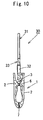
- FIG. 10 is a side view of the synthetic resin hanger equipped with synthetic resin clips; and
- FIG. 11 is a plan view of the synthetic resin hanger equipped with synthetic resin clips.
- A synthetic resin clip by this invention and a hanger with clips, provided with the synthetic resin clips, shall be described as
Embodiment 1 andEmbodiment 2, respectively, based on the drawings. - FIG. 1 is a perspective view of a synthetic resin clip, FIG. 2 is a front view of the synthetic resin clip, FIG. 3 is a longitudinal sectional view of the synthetic resin clip, FIG. 4 is a plan view of the synthetic resin clip, FIG. 5 is a right side view of the synthetic resin clip, FIG. 6 is a left side view of the synthetic resin clip, and FIG. 7 is an exploded view of the synthetic resin clip prior to assembly, and in the FIGURES,
symbol 1 indicates the synthetic resin clip in its entirety. - This
synthetic resin clip 1 is arranged by making a pair ofclip members synthetic resin spring 3 acrossclip members - As shown in FIGS. 3 and 7,
synthetic resin spring 3 is formed of a composite material synthetic resin having high-density carbonate resin as the main component and to have an inverted "U" shape that is thick at a folded-back portion 3a and becomes gradually thinner at thetips 3b, and at the inner surface of eachtip 3b portion, alatching protrusion 4 is protruded to form a hook-likeengaging portion 5. - As shown in FIG. 7,
clip members synthetic resin spring 3 is fitted, are molded in a state wherein opposingsurfaces thin portion 6. - As shown in FIGS. 3, 5, and 6, each of
clip members clamping portion 7, which clampingly hold clothes, etc., formed at one end portion (the lower end portion), has a receivingportion 8, which receives anengaging portion 5 of the above-mentionedsynthetic resin spring 3, formed at a substantially central portion, and has anoperating portion 9, by whichsynthetic resin clip 1 is operated to open against the springing force ofsynthetic resin spring 3, formed at the other end portion. - At side edge portions between the above-mentioned
operating portion 9 and receivingportion 6 are formedfulcrum portions 10, which are formed so that the tip portions thereof contact each other as shown in FIGS. 4 and 5, and at the contacting tip portions offulcrum portions 10 is formed apositioning portion 13, comprisingprotrusions 11, which are formed on one ofclip members holes 12, which are formed in theother clip member 2 and into which the above-mentionedprotrusions 11 are fitted. - The above-mentioned
thin portion 6, which connects the pair ofclip members positioning portion 13. - By the fitting of this
positioning portion 13, the pair ofclip members synthetic resin clip 1 are prevented from shifting with respect to each other in the upper, lower, left, and right directions. - Also as shown in FIG. 3, each receiving
portion 8 is formed by a hook-like protrudingportion 14 that receives anengaging portion 5 ofsynthetic resin spring 3. - Here, since
clip members thin portion 6 are formed by a pair of male and female dies (not shown), for forming the above-mentionedreceiving portions 8,window holes 15 for sliding the molding dies are required for forming hook-like protrudingportions 14. - As shown in FIGS. 1 to 3 and 7, each of
window holes 15 ofclipmembers receivingportions 8 is provided with a fly-apart preventingbar 16 that prevents the flying apart of broken pieces ofsynthetic resin spring 3 when it breaks. - This fly-apart preventing
bar 16 is positioned so as to cross awindow hole 15 vertically at a substantially central position and at a thin width, and upper andlower end portions lower edges window hole 15. A fly-apart preventingportion 17 is formed by this fly-apart preventingbar 16 and a portion, extending fromupper edge 15a ofwindow hole 15, which is connected toupper end portion 16a of fly-apart preventingbar 16, to operatingportion 9 and covering the folded-back portion 3a side ofsynthetic resin spring 3. - Sliding slits 18, for the dies that form the
receiving portion 8 side surface of fly-apart preventingbar 16, are formed in receivingportion 8 that opposes fly-apart preventingbar 16. - As shown in FIG. 3,
insertion spaces 19, for inserting the tip portions ofsynthetic resin spring 3, are formed in the direction of sliding of the dies (the horizontal direction in the FIGURE) between upper end portions 8a of receivingportions 8 andupper edges 15a ofwindow holes 15 and fly-apart preventingbars 16. - In the FIGURE,
symbol 20 indicates reinforcing ribs that are formed as two strips extending from the vicinity oflower edge 15b of the above-mentionedwindow hole 15 to the vicinity of an end portion (vertical end portion in the FIGURE) ofclamping portion 7. - With
synthetic resin clip 1, formed as described above, first, therespective clip members thin portion 6, are bent atthin portion 6 andsurface portions portions 7 ofsynthetic resin clip 1 are made to contact each other. - And when
synthetic resin spring 3 is then inserted from above bothclip members latching protrusions 4, formed on the inner surfaces of tip portions, are engaged with the respective receivingportions 8 ofclipmembers synthetic resin clip 1 is assembled. - With
synthetic resin clip 1 that is thus assembled, operatingportions 9 are operated to push apart clampingportions 7 against the elastic force ofsynthetic resin spring 3 and upon clamping a garment (not shown) here, the garment is passed through a needle inspector to perform needle inspection. - As such use of
synthetic resin clips 1 is repeated,synthetic resin spring 3 becomes cracked due to secular change, etc., and becomes broken in some cases. - In regard to the location of such breakage, breakage tends to occur readily at
portions 3c at whichsynthetic resin spring 3 becomes straight from folded-back portion 3a, the constricted base end portions ofengaging portions 5 from the inner surface of which latchingprotrusions 4 are protruded, and other portions at which the shape ofsynthetic resin spring 3 changes since stress tends to concentrate at such locations. However, in all cases, broken pieces that tend to fly apart fromwindow holes 15 due to breakage will be stopped definitely by fly-apart preventingbars 16 formed inwindow holes 15. - The flying apart of broken pieces can thereby be prevented and
synthetic resin clip 1 of a high degree of safety can be provided. - Though in the present example, the pair of synthetic
resin clip members thin portion 6, this invention is not limited thereto, and each ofclip members - With the above-described embodiment, the present invention can be applied as a clothespin in the case of a small clip and as a futon clip, used for drying a futon, in the case of a large clip.
- As shown in FIGS. 8 to 11, this embodiment is a
hanger 30, equipped withsynthetic resin clips 1 of the above-described embodiment. - With this
hanger 30, equipped withsynthetic resin clips 1, oneclip member 2, of the pair ofclip members thin portion 6 as described withEmbodiment 1, is integrally formed at each of both tip portions (left and right tip portions in the FIGURE) of anarm 32, having a hanginghook 31 formed at a central portion. - That is as described above, with
synthetic resin clip 1, engagingportions 5 are formed on inner surface portions of the tips ofsynthetic resin spring 3, which is formed to a "U" shape by being folded back at an intermediate portion, window holes 15 for sliding of molding dies are formed on outer portions ofclip members portions 8, which engage with engagingportions 5, at inner portions ofclip members insertion spaces 19, into which the tip portions ofsynthetic resin spring 3 are inserted, are formed in the direction of sliding of the dies betweenupper edges 15a of window holes 15 and upper end portions 8a of receivingportions 8. - A fly-apart preventing
bar 16 is then disposed across upper andlower edges window hole 15, and engagingportions 5 ofsynthetic resin spring 3 are engaged with receivingportions 8 of the pair ofclip members - With
hanger 30 with synthetic resin clips of the above-described arrangement,hanger 30, in a state wherein a skirt, a pair of trousers, or other garment is clamped at thesynthetic resin clip 1 portions, can be inspected by a needle inspector (not shown) at a manufacturer of the garments. - The actions and effects, especially the fly-apart preventing function of
synthetic resin clips 1 provided onhanger 30 are the same as those of the above-describedEmbodiment 1. - In the FIGURES,
symbol 33 indicates a size indicator mounting portion, by which the size of the garment that is hung upon being clamped bysynthetic resin clips 1 is indicated. - Though with the present embodiment, an example where the
hook 31 portion ofhanger 30 is formed integral toarm 32 is illustrated, this inventionisnotlimited thereto, and obviously these components may be formed separately to make thehook 31 portion rotatable.
Claims (5)
- A synthetic resin clip (1), comprising:a synthetic resin spring (3) formed to a "U" shape by being folded back at an intermediate portion;engaging portions (5) formed on inner surface portions of tips of the synthetic resin spring;clip members (2);receiving portions (8) engaging with the engaging portions and formed at inner portions of the clip members;window holes (15) for sliding of molding dies formed on outer portions of the clip members; andinsertion spaces (19) for inserting the tip portions of the synthetic resin spring and formed in the direction of sliding of the dies between upper edges of the window holes and upper end portions of the receiving portions,wherein the engaging portions of the synthetic resin spring are engaged with the receiving portions of the pair of clip members that are made to oppose each other face-to-face,
characterized by
fly-apart preventing bars (16) disposed across the upper and lower edges of the window holes. - The synthetic resin clip according to Claim 1, wherein slits for the sliding of dies are formed at the receiving portions opposing the fly-apart preventing bars.
- The synthetic resin clip according to Claim 1 or 2, wherein the pair of clip members are connected by a bendable thin member (6).
- A hanger (30) provided, at an arm (32) having a hanging hook (31) formed on a central portion, with synthetic resin clips (1), each synthetic resin clip comprising:a synthetic resin spring (3) formed to a "U" shape by being folded back at an intermediate portion;engaging portions (5) formed on inner surface portions of tips of the synthetic resin spring;clip members (2);receiving portions (8) engaging with the engaging portions and formed at inner portions of the clip members;window holes (15) for sliding of molding dies formed on outer portions of the clip members; andinsertion spaces (19) for inserting the tip portions of the synthetic resin spring and formed in the direction of sliding of the dies between upper edges of the window holes and upper end portions of the receiving portions,wherein the engaging portions of the synthetic resin spring are engaged with the receiving portions of the pair of clipmembers that are made to oppose each other face-to-face,
characterized by
fly-apart preventing bars (16) disposed across the upper and lower edges of the window holes. - The hanger with synthetic resin clips according to Claim 4, wherein of each pair of clip members, connected by a bendable thin member (6), one clip member is integrally molded to a tip portion of the arm on the central portion of which the hanging hook is formed.
Applications Claiming Priority (1)
| Application Number | Priority Date | Filing Date | Title |
|---|---|---|---|
| JP2004246786A JP4101216B2 (en) | 2004-08-26 | 2004-08-26 | Synthetic resin clip and hanger with synthetic resin clip |
Publications (2)
| Publication Number | Publication Date |
|---|---|
| EP1629751A1 EP1629751A1 (en) | 2006-03-01 |
| EP1629751B1 true EP1629751B1 (en) | 2007-02-21 |
Family
ID=35064479
Family Applications (1)
| Application Number | Title | Priority Date | Filing Date |
|---|---|---|---|
| EP05255071A Not-in-force EP1629751B1 (en) | 2004-08-26 | 2005-08-17 | Synthetic resin clip and hanger with synthetic resin clips |
Country Status (7)
| Country | Link |
|---|---|
| US (1) | US7387223B2 (en) |
| EP (1) | EP1629751B1 (en) |
| JP (1) | JP4101216B2 (en) |
| CN (1) | CN1739425B (en) |
| AT (1) | ATE354305T1 (en) |
| DE (1) | DE602005000587D1 (en) |
| ES (1) | ES2282980T3 (en) |
Families Citing this family (24)
| Publication number | Priority date | Publication date | Assignee | Title |
|---|---|---|---|---|
| EP1494556B1 (en) * | 2002-02-15 | 2015-04-22 | Stanley F. Gouldson | Improved pinch grip hangers |
| JP2004167141A (en) * | 2002-11-22 | 2004-06-17 | Hideo Misumi | Hanger with clips and its manufacturing method |
| US7537142B2 (en) * | 2006-04-12 | 2009-05-26 | Wai Shing Plastic Products Ltd. | Pinch clip garment hanger with modular friction pads |
| US20070247819A1 (en) * | 2006-04-24 | 2007-10-25 | Foxconn Technology Co., Ltd. | Memory module assembly including heat dissipating members |
| DE102006033382B4 (en) * | 2006-07-12 | 2010-09-30 | Inpac Medizintechnik Gmbh | Holding and packaging device for a dental implant |
| JP2008080836A (en) * | 2006-09-26 | 2008-04-10 | Suruga Co Ltd | Object attaching tool and its removing method |
| JP4612644B2 (en) | 2007-02-23 | 2011-01-12 | 英雄 三角 | Synthetic resin clip and hanger with synthetic resin clip |
| TW201221788A (en) * | 2010-11-25 | 2012-06-01 | Pan-Chi Hong | Clip |
| CN102892260B (en) * | 2011-03-23 | 2015-09-02 | 深圳市福智软件技术有限公司 | A kind of clip of media player |
| JP5860645B2 (en) * | 2011-09-15 | 2016-02-16 | レック株式会社 | clothes hanger |
| CA153807S (en) * | 2013-05-13 | 2014-06-10 | Mainetti Uk Ltd | Garment hanger |
| JP6247335B2 (en) * | 2016-05-19 | 2017-12-13 | クロバー株式会社 | Sewing clip |
| CN106245286A (en) * | 2016-09-23 | 2016-12-21 | 广东工业大学 | A kind of clip |
| USD815845S1 (en) | 2017-05-12 | 2018-04-24 | Target Brands, Inc. | Hanger |
| US10918139B2 (en) * | 2017-06-06 | 2021-02-16 | Dina Sue Toth | Undergarment clip |
| USD831987S1 (en) | 2017-10-04 | 2018-10-30 | Target Brands, Inc. | Hanger |
| USD866200S1 (en) * | 2018-08-13 | 2019-11-12 | Target Brands, Inc. | Hanger |
| US11304553B2 (en) | 2018-09-17 | 2022-04-19 | Target Brands, Inc. | Hanger system with hanger coupling member |
| USD882969S1 (en) * | 2018-09-17 | 2020-05-05 | Target Brands, Inc. | Hanger |
| US20220389644A1 (en) * | 2019-11-07 | 2022-12-08 | Jenna Hally Rubenstein | Clothes hanger clips |
| CN112776251A (en) * | 2019-11-08 | 2021-05-11 | 宜家供应有限公司 | Clothes peg and manufacturing method thereof |
| USD929134S1 (en) * | 2020-05-04 | 2021-08-31 | Target Brands, Inc. | Hanger |
| USD929753S1 (en) * | 2020-05-04 | 2021-09-07 | Target Brands, Inc. | Hanger |
| DE102020007469A1 (en) * | 2020-08-17 | 2022-02-17 | Richard Rudolf Sepp | Wear protection with profile for a collar point |
Family Cites Families (16)
| Publication number | Priority date | Publication date | Assignee | Title |
|---|---|---|---|---|
| US3456262A (en) * | 1967-09-15 | 1969-07-15 | Hercules Clip Corp | Clamping device |
| US3946915A (en) * | 1974-12-05 | 1976-03-30 | A & E Plastik Pak Co., Inc. | Garment hanger with clamp guard |
| US4382531A (en) * | 1980-04-07 | 1983-05-10 | Independent Products Company, Inc. | Hanger with swivel hook and skirt and trouser clips |
| US4878276A (en) * | 1987-06-25 | 1989-11-07 | Peter G. A. Morrish | Spring clip |
| US5241728A (en) * | 1992-06-08 | 1993-09-07 | Selfix, Inc. | Resilient clip |
| US5318292A (en) * | 1992-07-31 | 1994-06-07 | Marco Nicholas A De | Towel clamp golf accessory |
| US5402558A (en) * | 1994-05-09 | 1995-04-04 | Selfix, Inc. | Resilient clip |
| JP2956956B2 (en) * | 1995-02-03 | 1999-10-04 | 英雄 三角 | Synthetic resin clip |
| JPH10147A (en) * | 1996-06-17 | 1998-01-06 | Chiyoda Shokai:Kk | Clip and hanger with it |
| US6098254A (en) * | 1998-07-14 | 2000-08-08 | Randy Hangers | Garment hanger clip release guard |
| US6119906A (en) * | 1999-02-25 | 2000-09-19 | Red Wing Products, Inc. | Hanger with integrated clips |
| US6422438B1 (en) * | 1999-03-01 | 2002-07-23 | Batts, Inc. | Garment hanger having one piece molded pinch clip with clip protection |
| US6050462A (en) * | 1999-04-27 | 2000-04-18 | Petrou; Nicoleon | Garment hanger with pinch clips |
| CN2388891Y (en) * | 1999-08-14 | 2000-07-26 | 洪礼表 | Hanger |
| JP2003204859A (en) * | 2002-01-15 | 2003-07-22 | Tosu:Kk | Synthetic resin-made pinch |
| JP2004167141A (en) * | 2002-11-22 | 2004-06-17 | Hideo Misumi | Hanger with clips and its manufacturing method |
-
2004
- 2004-08-26 JP JP2004246786A patent/JP4101216B2/en active Active
-
2005
- 2005-08-17 ES ES05255071T patent/ES2282980T3/en active Active
- 2005-08-17 EP EP05255071A patent/EP1629751B1/en not_active Not-in-force
- 2005-08-17 AT AT05255071T patent/ATE354305T1/en not_active IP Right Cessation
- 2005-08-17 DE DE602005000587T patent/DE602005000587D1/en active Active
- 2005-08-24 US US11/209,821 patent/US7387223B2/en active Active
- 2005-08-24 CN CN200510097753XA patent/CN1739425B/en active Active
Also Published As
| Publication number | Publication date |
|---|---|
| CN1739425B (en) | 2010-09-01 |
| ES2282980T3 (en) | 2007-10-16 |
| CN1739425A (en) | 2006-03-01 |
| JP2006061365A (en) | 2006-03-09 |
| ATE354305T1 (en) | 2007-03-15 |
| US20060042050A1 (en) | 2006-03-02 |
| JP4101216B2 (en) | 2008-06-18 |
| US7387223B2 (en) | 2008-06-17 |
| DE602005000587D1 (en) | 2007-04-05 |
| EP1629751A1 (en) | 2006-03-01 |
Similar Documents
| Publication | Publication Date | Title |
|---|---|---|
| EP1629751B1 (en) | Synthetic resin clip and hanger with synthetic resin clips | |
| EP0130165B1 (en) | Clip | |
| US20040099700A1 (en) | Hanger with clips and method of manufacturing the same | |
| CA1116378A (en) | Clamp construction for article hangers | |
| EP1961347B1 (en) | Synthetic resin clip and hanger comprising synthetic resin clip | |
| US4274564A (en) | Unitary garment retaining hanger | |
| EP1197908A2 (en) | Smart card connector and switch contact elements for it | |
| US10588383B2 (en) | Buckle | |
| TW201420900A (en) | A connector | |
| JP4838457B2 (en) | Watch band fastener | |
| US7708174B1 (en) | Top sizer for garment hanger | |
| JP3989875B2 (en) | Plastic hook | |
| JP3929530B2 (en) | Clothes hanger | |
| JP3408421B2 (en) | Clothes hanging clip | |
| KR100334385B1 (en) | Device for adjusting shoulder width in hanger | |
| KR200231529Y1 (en) | Buckle | |
| US2188534A (en) | Loop fastener | |
| CN209759856U (en) | Garment steamer support and garment steamer | |
| KR102191891B1 (en) | Clip and connector assembly | |
| KR200313805Y1 (en) | A medal-shaped tag which is easily assembled | |
| JP2003204859A (en) | Synthetic resin-made pinch | |
| JP3020807U (en) | Resin clip hook for clothing | |
| KR101172176B1 (en) | Hanger for a hanger tag | |
| CN114929073A (en) | Clothes hanger clamp | |
| JP3116916U (en) | Protruding clip and suspension structure |
Legal Events
| Date | Code | Title | Description |
|---|---|---|---|
| PUAI | Public reference made under article 153(3) epc to a published international application that has entered the european phase |
Free format text: ORIGINAL CODE: 0009012 |
|
| AK | Designated contracting states |
Kind code of ref document: A1 Designated state(s): AT BE BG CH CY CZ DE DK EE ES FI FR GB GR HU IE IS IT LI LT LU LV MC NL PL PT RO SE SI SK TR |
|
| AX | Request for extension of the european patent |
Extension state: AL BA HR MK YU |
|
| 17P | Request for examination filed |
Effective date: 20060519 |
|
| GRAP | Despatch of communication of intention to grant a patent |
Free format text: ORIGINAL CODE: EPIDOSNIGR1 |
|
| AKX | Designation fees paid |
Designated state(s): AT BE BG CH CY CZ DE DK EE ES FI FR GB GR HU IE IS IT LI LT LU LV MC NL PL PT RO SE SI SK TR |
|
| GRAS | Grant fee paid |
Free format text: ORIGINAL CODE: EPIDOSNIGR3 |
|
| GRAA | (expected) grant |
Free format text: ORIGINAL CODE: 0009210 |
|
| AK | Designated contracting states |
Kind code of ref document: B1 Designated state(s): AT BE BG CH CY CZ DE DK EE ES FI FR GB GR HU IE IS IT LI LT LU LV MC NL PL PT RO SE SI SK TR |
|
| PG25 | Lapsed in a contracting state [announced via postgrant information from national office to epo] |
Ref country code: SI Free format text: LAPSE BECAUSE OF FAILURE TO SUBMIT A TRANSLATION OF THE DESCRIPTION OR TO PAY THE FEE WITHIN THE PRESCRIBED TIME-LIMIT Effective date: 20070221 Ref country code: CH Free format text: LAPSE BECAUSE OF FAILURE TO SUBMIT A TRANSLATION OF THE DESCRIPTION OR TO PAY THE FEE WITHIN THE PRESCRIBED TIME-LIMIT Effective date: 20070221 Ref country code: PL Free format text: LAPSE BECAUSE OF FAILURE TO SUBMIT A TRANSLATION OF THE DESCRIPTION OR TO PAY THE FEE WITHIN THE PRESCRIBED TIME-LIMIT Effective date: 20070221 Ref country code: LI Free format text: LAPSE BECAUSE OF FAILURE TO SUBMIT A TRANSLATION OF THE DESCRIPTION OR TO PAY THE FEE WITHIN THE PRESCRIBED TIME-LIMIT Effective date: 20070221 Ref country code: BE Free format text: LAPSE BECAUSE OF FAILURE TO SUBMIT A TRANSLATION OF THE DESCRIPTION OR TO PAY THE FEE WITHIN THE PRESCRIBED TIME-LIMIT Effective date: 20070221 Ref country code: FI Free format text: LAPSE BECAUSE OF FAILURE TO SUBMIT A TRANSLATION OF THE DESCRIPTION OR TO PAY THE FEE WITHIN THE PRESCRIBED TIME-LIMIT Effective date: 20070221 Ref country code: NL Free format text: LAPSE BECAUSE OF FAILURE TO SUBMIT A TRANSLATION OF THE DESCRIPTION OR TO PAY THE FEE WITHIN THE PRESCRIBED TIME-LIMIT Effective date: 20070221 Ref country code: DK Free format text: LAPSE BECAUSE OF FAILURE TO SUBMIT A TRANSLATION OF THE DESCRIPTION OR TO PAY THE FEE WITHIN THE PRESCRIBED TIME-LIMIT Effective date: 20070221 Ref country code: AT Free format text: LAPSE BECAUSE OF FAILURE TO SUBMIT A TRANSLATION OF THE DESCRIPTION OR TO PAY THE FEE WITHIN THE PRESCRIBED TIME-LIMIT Effective date: 20070221 |
|
| REG | Reference to a national code |
Ref country code: GB Ref legal event code: FG4D |
|
| REG | Reference to a national code |
Ref country code: CH Ref legal event code: EP |
|
| REF | Corresponds to: |
Ref document number: 602005000587 Country of ref document: DE Date of ref document: 20070405 Kind code of ref document: P |
|
| REG | Reference to a national code |
Ref country code: IE Ref legal event code: FG4D |
|
| PG25 | Lapsed in a contracting state [announced via postgrant information from national office to epo] |
Ref country code: BG Free format text: LAPSE BECAUSE OF FAILURE TO SUBMIT A TRANSLATION OF THE DESCRIPTION OR TO PAY THE FEE WITHIN THE PRESCRIBED TIME-LIMIT Effective date: 20070521 Ref country code: SE Free format text: LAPSE BECAUSE OF FAILURE TO SUBMIT A TRANSLATION OF THE DESCRIPTION OR TO PAY THE FEE WITHIN THE PRESCRIBED TIME-LIMIT Effective date: 20070521 |
|
| PG25 | Lapsed in a contracting state [announced via postgrant information from national office to epo] |
Ref country code: IS Free format text: LAPSE BECAUSE OF FAILURE TO SUBMIT A TRANSLATION OF THE DESCRIPTION OR TO PAY THE FEE WITHIN THE PRESCRIBED TIME-LIMIT Effective date: 20070621 |
|
| PG25 | Lapsed in a contracting state [announced via postgrant information from national office to epo] |
Ref country code: PT Free format text: LAPSE BECAUSE OF FAILURE TO SUBMIT A TRANSLATION OF THE DESCRIPTION OR TO PAY THE FEE WITHIN THE PRESCRIBED TIME-LIMIT Effective date: 20070723 |
|
| NLV1 | Nl: lapsed or annulled due to failure to fulfill the requirements of art. 29p and 29m of the patents act | ||
| REG | Reference to a national code |
Ref country code: CH Ref legal event code: PL |
|
| REG | Reference to a national code |
Ref country code: ES Ref legal event code: FG2A Ref document number: 2282980 Country of ref document: ES Kind code of ref document: T3 |
|
| PG25 | Lapsed in a contracting state [announced via postgrant information from national office to epo] |
Ref country code: SK Free format text: LAPSE BECAUSE OF FAILURE TO SUBMIT A TRANSLATION OF THE DESCRIPTION OR TO PAY THE FEE WITHIN THE PRESCRIBED TIME-LIMIT Effective date: 20070221 |
|
| PLBE | No opposition filed within time limit |
Free format text: ORIGINAL CODE: 0009261 |
|
| STAA | Information on the status of an ep patent application or granted ep patent |
Free format text: STATUS: NO OPPOSITION FILED WITHIN TIME LIMIT |
|
| PG25 | Lapsed in a contracting state [announced via postgrant information from national office to epo] |
Ref country code: CZ Free format text: LAPSE BECAUSE OF FAILURE TO SUBMIT A TRANSLATION OF THE DESCRIPTION OR TO PAY THE FEE WITHIN THE PRESCRIBED TIME-LIMIT Effective date: 20070221 Ref country code: RO Free format text: LAPSE BECAUSE OF FAILURE TO SUBMIT A TRANSLATION OF THE DESCRIPTION OR TO PAY THE FEE WITHIN THE PRESCRIBED TIME-LIMIT Effective date: 20070221 |
|
| 26N | No opposition filed |
Effective date: 20071122 |
|
| PG25 | Lapsed in a contracting state [announced via postgrant information from national office to epo] |
Ref country code: DE Free format text: LAPSE BECAUSE OF FAILURE TO SUBMIT A TRANSLATION OF THE DESCRIPTION OR TO PAY THE FEE WITHIN THE PRESCRIBED TIME-LIMIT Effective date: 20070522 Ref country code: LV Free format text: LAPSE BECAUSE OF FAILURE TO SUBMIT A TRANSLATION OF THE DESCRIPTION OR TO PAY THE FEE WITHIN THE PRESCRIBED TIME-LIMIT Effective date: 20070221 |
|
| PG25 | Lapsed in a contracting state [announced via postgrant information from national office to epo] |
Ref country code: LT Free format text: LAPSE BECAUSE OF FAILURE TO SUBMIT A TRANSLATION OF THE DESCRIPTION OR TO PAY THE FEE WITHIN THE PRESCRIBED TIME-LIMIT Effective date: 20070221 |
|
| PG25 | Lapsed in a contracting state [announced via postgrant information from national office to epo] |
Ref country code: MC Free format text: LAPSE BECAUSE OF NON-PAYMENT OF DUE FEES Effective date: 20070831 Ref country code: GR Free format text: LAPSE BECAUSE OF FAILURE TO SUBMIT A TRANSLATION OF THE DESCRIPTION OR TO PAY THE FEE WITHIN THE PRESCRIBED TIME-LIMIT Effective date: 20070522 |
|
| PG25 | Lapsed in a contracting state [announced via postgrant information from national office to epo] |
Ref country code: IE Free format text: LAPSE BECAUSE OF NON-PAYMENT OF DUE FEES Effective date: 20070817 |
|
| PG25 | Lapsed in a contracting state [announced via postgrant information from national office to epo] |
Ref country code: EE Free format text: LAPSE BECAUSE OF FAILURE TO SUBMIT A TRANSLATION OF THE DESCRIPTION OR TO PAY THE FEE WITHIN THE PRESCRIBED TIME-LIMIT Effective date: 20070221 |
|
| PG25 | Lapsed in a contracting state [announced via postgrant information from national office to epo] |
Ref country code: CY Free format text: LAPSE BECAUSE OF FAILURE TO SUBMIT A TRANSLATION OF THE DESCRIPTION OR TO PAY THE FEE WITHIN THE PRESCRIBED TIME-LIMIT Effective date: 20070221 |
|
| PG25 | Lapsed in a contracting state [announced via postgrant information from national office to epo] |
Ref country code: LU Free format text: LAPSE BECAUSE OF NON-PAYMENT OF DUE FEES Effective date: 20070817 |
|
| PG25 | Lapsed in a contracting state [announced via postgrant information from national office to epo] |
Ref country code: HU Free format text: LAPSE BECAUSE OF FAILURE TO SUBMIT A TRANSLATION OF THE DESCRIPTION OR TO PAY THE FEE WITHIN THE PRESCRIBED TIME-LIMIT Effective date: 20070822 Ref country code: TR Free format text: LAPSE BECAUSE OF FAILURE TO SUBMIT A TRANSLATION OF THE DESCRIPTION OR TO PAY THE FEE WITHIN THE PRESCRIBED TIME-LIMIT Effective date: 20070221 |
|
| REG | Reference to a national code |
Ref country code: FR Ref legal event code: PLFP Year of fee payment: 12 |
|
| REG | Reference to a national code |
Ref country code: FR Ref legal event code: PLFP Year of fee payment: 13 |
|
| REG | Reference to a national code |
Ref country code: FR Ref legal event code: PLFP Year of fee payment: 14 |
|
| PGFP | Annual fee paid to national office [announced via postgrant information from national office to epo] |
Ref country code: IT Payment date: 20210712 Year of fee payment: 17 Ref country code: FR Payment date: 20210714 Year of fee payment: 17 |
|
| PGFP | Annual fee paid to national office [announced via postgrant information from national office to epo] |
Ref country code: ES Payment date: 20210907 Year of fee payment: 17 Ref country code: GB Payment date: 20210707 Year of fee payment: 17 |
|
| GBPC | Gb: european patent ceased through non-payment of renewal fee |
Effective date: 20220817 |
|
| PG25 | Lapsed in a contracting state [announced via postgrant information from national office to epo] |
Ref country code: IT Free format text: LAPSE BECAUSE OF NON-PAYMENT OF DUE FEES Effective date: 20220817 Ref country code: FR Free format text: LAPSE BECAUSE OF NON-PAYMENT OF DUE FEES Effective date: 20220831 |
|
| REG | Reference to a national code |
Ref country code: ES Ref legal event code: FD2A Effective date: 20230928 |
|
| PG25 | Lapsed in a contracting state [announced via postgrant information from national office to epo] |
Ref country code: GB Free format text: LAPSE BECAUSE OF NON-PAYMENT OF DUE FEES Effective date: 20220817 Ref country code: ES Free format text: LAPSE BECAUSE OF NON-PAYMENT OF DUE FEES Effective date: 20220818 |