EP1629191B1 - Pump assembly - Google Patents
Pump assembly Download PDFInfo
- Publication number
- EP1629191B1 EP1629191B1 EP04734539.2A EP04734539A EP1629191B1 EP 1629191 B1 EP1629191 B1 EP 1629191B1 EP 04734539 A EP04734539 A EP 04734539A EP 1629191 B1 EP1629191 B1 EP 1629191B1
- Authority
- EP
- European Patent Office
- Prior art keywords
- pump
- plunger
- pump assembly
- tappet
- radially extending
- Prior art date
- Legal status (The legal status is an assumption and is not a legal conclusion. Google has not performed a legal analysis and makes no representation as to the accuracy of the status listed.)
- Active
Links
Images

Classifications
-
- F—MECHANICAL ENGINEERING; LIGHTING; HEATING; WEAPONS; BLASTING
- F02—COMBUSTION ENGINES; HOT-GAS OR COMBUSTION-PRODUCT ENGINE PLANTS
- F02M—SUPPLYING COMBUSTION ENGINES IN GENERAL WITH COMBUSTIBLE MIXTURES OR CONSTITUENTS THEREOF
- F02M59/00—Pumps specially adapted for fuel-injection and not provided for in groups F02M39/00 -F02M57/00, e.g. rotary cylinder-block type of pumps
- F02M59/02—Pumps specially adapted for fuel-injection and not provided for in groups F02M39/00 -F02M57/00, e.g. rotary cylinder-block type of pumps of reciprocating-piston or reciprocating-cylinder type
- F02M59/10—Pumps specially adapted for fuel-injection and not provided for in groups F02M39/00 -F02M57/00, e.g. rotary cylinder-block type of pumps of reciprocating-piston or reciprocating-cylinder type characterised by the piston-drive
- F02M59/102—Mechanical drive, e.g. tappets or cams
-
- F—MECHANICAL ENGINEERING; LIGHTING; HEATING; WEAPONS; BLASTING
- F02—COMBUSTION ENGINES; HOT-GAS OR COMBUSTION-PRODUCT ENGINE PLANTS
- F02M—SUPPLYING COMBUSTION ENGINES IN GENERAL WITH COMBUSTIBLE MIXTURES OR CONSTITUENTS THEREOF
- F02M59/00—Pumps specially adapted for fuel-injection and not provided for in groups F02M39/00 -F02M57/00, e.g. rotary cylinder-block type of pumps
- F02M59/44—Details, components parts, or accessories not provided for in, or of interest apart from, the apparatus of groups F02M59/02 - F02M59/42; Pumps having transducers, e.g. to measure displacement of pump rack or piston
- F02M59/46—Valves
- F02M59/462—Delivery valves
-
- F—MECHANICAL ENGINEERING; LIGHTING; HEATING; WEAPONS; BLASTING
- F02—COMBUSTION ENGINES; HOT-GAS OR COMBUSTION-PRODUCT ENGINE PLANTS
- F02M—SUPPLYING COMBUSTION ENGINES IN GENERAL WITH COMBUSTIBLE MIXTURES OR CONSTITUENTS THEREOF
- F02M63/00—Other fuel-injection apparatus having pertinent characteristics not provided for in groups F02M39/00 - F02M57/00 or F02M67/00; Details, component parts, or accessories of fuel-injection apparatus, not provided for in, or of interest apart from, the apparatus of groups F02M39/00 - F02M61/00 or F02M67/00; Combination of fuel pump with other devices, e.g. lubricating oil pump
- F02M63/0012—Valves
- F02M63/007—Details not provided for in, or of interest apart from, the apparatus of the groups F02M63/0014 - F02M63/0059
- F02M63/0075—Stop members in valves, e.g. plates or disks limiting the movement of armature, valve or spring
-
- F—MECHANICAL ENGINEERING; LIGHTING; HEATING; WEAPONS; BLASTING
- F04—POSITIVE - DISPLACEMENT MACHINES FOR LIQUIDS; PUMPS FOR LIQUIDS OR ELASTIC FLUIDS
- F04B—POSITIVE-DISPLACEMENT MACHINES FOR LIQUIDS; PUMPS
- F04B1/00—Multi-cylinder machines or pumps characterised by number or arrangement of cylinders
- F04B1/04—Multi-cylinder machines or pumps characterised by number or arrangement of cylinders having cylinders in star- or fan-arrangement
- F04B1/0404—Details or component parts
- F04B1/0426—Arrangements for pressing the pistons against the actuated cam; Arrangements for connecting the pistons to the actuated cam
-
- F—MECHANICAL ENGINEERING; LIGHTING; HEATING; WEAPONS; BLASTING
- F02—COMBUSTION ENGINES; HOT-GAS OR COMBUSTION-PRODUCT ENGINE PLANTS
- F02M—SUPPLYING COMBUSTION ENGINES IN GENERAL WITH COMBUSTIBLE MIXTURES OR CONSTITUENTS THEREOF
- F02M63/00—Other fuel-injection apparatus having pertinent characteristics not provided for in groups F02M39/00 - F02M57/00 or F02M67/00; Details, component parts, or accessories of fuel-injection apparatus, not provided for in, or of interest apart from, the apparatus of groups F02M39/00 - F02M61/00 or F02M67/00; Combination of fuel pump with other devices, e.g. lubricating oil pump
- F02M63/02—Fuel-injection apparatus having several injectors fed by a common pumping element, or having several pumping elements feeding a common injector; Fuel-injection apparatus having provisions for cutting-out pumps, pumping elements, or injectors; Fuel-injection apparatus having provisions for variably interconnecting pumping elements and injectors alternatively
- F02M63/0225—Fuel-injection apparatus having a common rail feeding several injectors ; Means for varying pressure in common rails; Pumps feeding common rails
Definitions
- the invention relates to a pump assembly suitable for use in a common rail fuel injection system for supplying high pressure fuel to a compression ignition internal combustion engine.
- the invention relates to a pump assembly of the type having a cam rider mounted upon an engine driven cam and an intermediate drive member which is coupled to a pumping plunger and which co-operates with the cam rider, in use, so as to impart reciprocating, pumping motion to the plunger.
- a known common rail fuel pump of radial pump design three pumping plungers are arranged at equi-angularly spaced locations around an engine driven cam. Each plunger is mounted within a plunger bore provided in a main pump housing. As the cam is driven in use, the plungers are caused to reciprocate within their bores in a phased, cyclical manner. As the plungers reciprocate, each causes pressurisation of fuel within a pump chamber defined at one end of the associated plunger bore. The delivery of fuel from the pump chambers to a common high pressure supply line is controlled by means of delivery valves. The high pressure line supplies fuel to a common rail, or other accumulator volume, for delivery to the downstream injectors of the common rail fuel system.
- the cam carries a cam rider which extends co-axially with the drive shaft and is provided with a plurality of flats, one for each of the plungers.
- An intermediate drive member in the form of a tappet co-operates with the flat on the cam rider and couples to the plunger so that, as the tappet is driven upon rotation of the cam, drive is imparted to the plunger.
- a common rail fuel pump of radial pump design is described in US Patent No. 6250893 .
- This pump has an eccentrically driven shaft supported in a pump housing, around which a ring with three flat faces is disposed to impart drive to three radially mounted pistons. These pistons are disposed in cylinder chambers and are reciprocated by the motion of the drive shaft.
- a tappet is mounted around each cylinder, the tappet being guided in a bore of the main pump housing.
- Each cylinder chamber is mounted between the main pump housing and a composite head part containing an inlet and an outlet valve.
- a pump assembly for use in delivering fuel to a common rail of an internal combustion engine, the pump assembly comprising: a pumping plunger, an intermediate drive member and an engine-driven cam, wherein the pumping plunger is co-operable with the intermediate drive member, and the intermediate drive member is further co-operable with the engine-drive cam, in use, so as to impart drive to the pumping plunger.
- the pump assembly further comprises a cam rider member having an inner surface which is co-operable with the cam and an outer surface which is co-operable with the intermediate drive member, a main pump housing provided with a radially extending opening within which is received, at a first end thereof, a separate pump head and, at a second end thereof, the intermediate drive member so that the main pump housing serves to guide movement of the intermediate drive member, in use, characterised in that the separate pump head is an integral unit having a head portion and an extension which projects into the radially extending opening and which defines a plunger bore, which serves to guide movement of the pumping plunger, the extension providing an increased sealing length for the pumping plunger, and wherein the head portion defines a blind end of the plunger bore which, together with a radially outer face of the pumping plunger, defines a pump chamber in which fuel is pressurised as the pumping plunger is driven.
- the pump assembly comprises first, second and third plungers which are equi-angularly spaced around the engine drive cam, the cam rider member being provided with first, second and third surfaces for co-operation with first, second and third intermediate drive members, respectively, each intermediate drive member being coupled to an associated one of the plungers and wherein each of the intermediate drive members is guided within a respective one of first, second or third radially extending openings provided in the main pump housing, each of the first, second and third plungers being guided within a respective one of first, second or third plunger bores provided within a respective one of first, second or third pump heads mounted upon the main pump housing.
- This preferred embodiment of the pump assembly may therefore be considered as having three pump 'units' radially spaced around the cam, each pump unit having a pump head and a plunger coupled to an intermediate drive member for mounting within a radially extending opening in the main pump housing.
- the radially extending opening defines a chamber which is flooded with fuel and within which the intermediate drive member reciprocates, in use.
- the pump assembly of this preferred embodiment of the invention is not limited to having three pump units, and a greater number of pump units may be provided, if required.
- the intermediate drive member takes the form of a tappet, typically a bucket-shaped tappet, having facing tappet sidewalls and a tappet base, wherein the tappet side walls are guided within the main pump housing and the tappet base co-operates with a flat on the outer surface of the cam rider member.
- the pump assembly with means for allowing fuel to be displaced from, and supplied to, the chamber defined by the radially extending opening in the main pump housing.
- each tappet sidewall may be provided with a sidewall opening in the form of a window to allow fuel to flow into the chamber and around the tappet during the plunger return stroke, and also to allow fuel to be displaced from the chamber during the plunger pumping stroke.
- the pump assembly has several benefits over known pump assemblies. As each plunger is guided within a separate pump head (i.e. a housing part separate from the other pump heads), and each tappet is guided within the main pump housing which is separate from the pump heads, the guidance bores are much easier to machine than in an assembly in which the plunger and the tappet are both guided within the main pump housing. This may pose another problem as any misalignment or 'tilt' of the pump heads relative to the main pump housing can lead to off-axis side loading of the plungers and/or tappets, resulting in an undesirable degree of wear. With this in mind, it is a preferable feature of the invention that the tappets are guided within the main pump housing, which is that part of the pump assembly carrying and locating both the drive shaft and the cam rider member.
- each tappet is provided with a roller which co-operates with the outer surface of the cam.
- the benefit is achieved as the requirement for individual rollers for each tappet is avoided by the use of the single cam rider which drives all three plungers and tappets.
- the cam rider In use, as the cam is rotated by the drive shaft, the cam rider is caused to ride over the cam surface.
- the flat, or flattened region, of the surface of the cam rider member co-operates with the base of the tappet with the result that the tappet is driven axially, radially outward from the cam shaft, whilst a degree of relative sliding movement between the rider flat and the tappet occurs in a lateral direction (as the cam rider is able to slide relative to the axially guided tappet).
- the main pump housing is provided with an axially extending opening for receiving the drive shaft.
- each of first, second and third radially extending openings communicate, at respective inner ends thereof, with the axially extending opening in the main pump housing.
- the cam rider preferable takes the form of a generally tubular member arranged co-axially with the drive shaft.
- the main pump housing includes an insert means which defines a guide path for the tappet.
- an insert member may be received within the inner end of each of the first, second and third radially extending openings so that each insert member defines a guide path for a respective one of the tappets.
- the insert member may be of generally cylindrical form such that it takes the form of a sleeve.
- the plunger bore and the insert member are substantially co-axially aligned.
- the insert means may alternatively take the form of a hardened coating e.g. a steel coating. This is particularly advantageous if the main pump housing is to be formed from cast iron, which is convenient and relatively light, as the hardness of the steel insert means (e.g. sleeve member or coating) avoids wear of the main pump housing.
- a hardened coating e.g. a steel coating.
- an internal surface of the radially extending opening may define the guide path for the tappet.
- each pump head is provided with an extension which projects into the respective radially extending opening to define an increased plunger sealing length. This has the benefit of improving pump efficiency as losses due to leakage are reduced.
- each pump unit has an outlet valve arrangement including a valve member which is engageable with a valve seating to open and close communication between the pump chamber and the common rail, whereby opening movement of the valve member is limited by means of a stop plug which defines at least two flow paths for fuel.
- the stop plug has an outer surface provided with at least two axially extending recesses to define a flow path for high pressure fuel.
- An outlet valve of this construction is particularly convenient to manufacture.
- the advantageous features of the present invention are applicable not only to a pump assembly having three pump units (i.e. three plungers) but also to pump assemblies having just two pump units.
- the pump assembly may include only first and second pump units.
- the pump assembly may comprise a first plunger which is reciprocable within a first plunger bore provided in a first pump head and co-operable with a first intermediate drive member which is reciprocable within a first radially extending opening provided in the main pump housing, the pump assembly further comprising a second plunger which is reciprocable within a second plunger bore provided in a second pump head and co-operable with a second intermediate drive member which is reciprocable within a second radially extending opening provided in the main pump housing, wherein the first and second pump heads are received within a respective one of the first and second radially extending openings, at radially outermost ends thereof, said openings being located substantially diametrically opposite one another within the main pump housing.
- a pump assembly includes a first housing part in the form of a main pump housing 10 provided with an axially extending opening 17.
- a cam drive shaft 12 is mounted within, and extends through, the axially extending opening 17 when the assembly is installed in the engine within which it is to be used.
- the central axis 13 of the drive shaft 12 is identified, although the drive shaft itself is not visible in this view.
- the drive shaft 12 co-operates with a cam arrangement including an eccentrically mounted cam 11.
- the main pump housing 10 projects, at its front end, to accommodate the near full length of the drive shaft 12.
- the assembly is closed at its back end by a rear closure plate (not visible in the drawings) and at its front end by a front closure plate 15 having three ears or flanges 16, each provided with a respective opening 14 for receiving a suitable fixing for mounting the pump assembly to the engine.
- the front closure plate 15 has an rearwardly directed nose (not visible) which projects into the main pump housing 10.
- the main pump housing 10 is typically formed from cast iron and is provided with first, second and third radially extending openings or through bores 18a, 18b, 18c respectively, each of which communicates, at a radially inner end thereof, with the axially extending opening 17 through the housing 10.
- a radially outer end of each opening 18a, 18b, 18c receives a pump head, first, second and third ones of which are identified by numerals 20a, 20b and 20c respectively.
- Each pump head 20a, 20b, 20c is substantially identical to the others and so only the first pump head 20a will be described in detail below.
- the first pump head 20a includes a head portion 22 and a downwardly extending extension 24 (in the orientation shown) which projects into a radially outer end of the opening 18a in the main pump housing 10.
- the extension 24 is provided with a plunger bore 26 within which a pumping plunger 28 is received.
- a blind end of the plunger bore 26 is located within the head portion 22 of the first pump head 20a.
- the blind end of the plunger bore 26 defines, together with a radially outer end face of the plunger 28, a pump chamber 30 to which fuel at relatively low pressure is delivered and within which pressurisation of fuel to a relatively high level suitable for injection takes place as the plunger 28 is driven to perform a pumping stroke, in use, upon rotation of the drive shaft 12.
- extension 24 of the pump head 22 provides an increased sealing length for the plunger bore 26, which tends to reduce high pressure fuel leakage from the chamber 30.
- a radially inner end of the radially extending opening 18a receives an intermediate drive member for the plunger 28 in the form of a tappet 34.
- the tappet is of U-shaped or channelled cross section, having first and second opposing sidewalls interconnected by a tappet base. Because of its construction, the tappet may be referred to as a "bucket tappet".
- the tappet 34 locates within a radially inner end of the opening 18a so that an internal surface of the opening 18a serves to guide axial movement of the tappet 34, in use. It is therefore the main pump housing 10 which defines the guide surface for axial tappet motion and which constrains lateral tappet motion across the cam rider 38.
- the bucket tappet 34 is coupled to the plunger 28 by means of a circlip 29, as shown in Figure 3 .
- other coupling means may be provided for connecting the tappet 34 and the plunger 28 together, providing that the coupling is such that motion of one (e.g. the tappet) results in motion of the other (e.g. the plunger) during at least a part of the plunger's stroke.
- the tappet 34 and the plunger 28 may be coupled together so that a degree of relative movement between them, along the main plunger axis, is permitted.
- the upper surface of the tappet base is provided with recess for locating one end of a plunger return spring 36.
- the spring 36 is mounted concentrically with both the plunger 28 and the extension 24 and occupies a clearance region or chamber defined between the internal surface of the opening 18a and the extension 24.
- the other end of the plunger return spring 36 abuts the head portion 22 of the first pump head 20a so that the spring 36 serves to apply a return biasing force to the plunger 28, and hence to the tappet 34, to drive a plunger return stroke.
- the drive shaft 12 co-operates with the cam 11 which, in turn, is co-operable with a generally tubular cam rider member 38 which extends co-axially with the shaft 12.
- the cam rider 38 On its outer surface the cam rider 38 is provided with first, second and third flattened surfaces 38a, 38b, 38c, referred to as flats.
- Each one of the flats 38a, 38b, 38c co-operates with the base surface of the tappet 34 for a respective one of the plungers 28.
- the tappet 34 for the plunger 28 of the first pump head 20a co-operates with the first flat 38a on the cam rider 38.
- the tappet 34 is caused to reciprocate within the opening 18a and the plunger 28 is caused to reciprocate within the plunger bore 26.
- the tappet 34 and the pumping plunger 28 are therefore driven together causing the plunger 28 to perform a pumping cycle including a pumping stroke, during which the tappet 34 and the plunger 28 are driven radially outward from the shaft (i.e. for the first pump head 20a, vertically upwards in Figures 1 to 3 ) to reduce the volume of the pump chamber 30.
- the pumping plunger 28 is driven inwardly within its plunger bore 26 and fuel within the pump chamber 30 is pressurised to a relatively high level in a manner which would be familiar to those skilled in this technology field.
- the tappet 34 and the plunger 28 are urged in a radially inward direction (i.e. for the first pump head 20a, vertically downwards in Figures 1 to 3 ) to increase the volume of the pump chamber 30.
- the plunger 28 is urged outwardly from the plunger bore 26 and fuel at relatively low pressure fills the associated pump chamber 30.
- plunger return spring 36 serves to urge the plunger 28 to perform its return stroke and additionally ensures contact is maintained between the tappet 34 and the flat 38a of the rider 38 at all times throughout the pumping cycle.
- the tappet 34 and the plunger 28 perform cyclical sinusoidal motion and are driven at a maximum frequency of about 120 Hz.
- the tappet 34 typically has a range of travel, between bottom-dead-centre and top-dead-centre, of around 10 millimetres.
- plunger movement is guided by the pump head 18a (i.e. within the plunger bore 26), whereas tappet moment is guided by the main pump housing 10 (i.e. within the radially extending opening 18a).
- the side walls of the tappet 34 have outer surfaces of generally cylindrical form, and it is these outer surfaces which cooperate with a substantially cylindrical internal surface of the opening 18a such that motion of the tappet 34 is guided as it reciprocates.
- Tilt problems may otherwise arise, for example, if surface to surface contact between the head portion 22 of the pump head and the main pump housing 10 is not exactly flat.
- the main pump housing 10 is machined so as to minimise geometric deviations which would affect the ability of the flat 'sliding' surface of the tappet base to be properly in contact with the corresponding flat 38a on the cam rider 38. Deviations possibly arise due to the need for accurate perpendicularity between the axis of the opening 18a, 18b, 18c and that of the shaft bearing installations, and the angular spacing of the openings 18a, 18b, 18c in their common plane at right angles to the shaft axis.
- the main pump housing 10 also supports the shaft bearings as precisely as is practical.
- the rear bearing is fitted directly into the main housing 10, while the front bearing is in the front closure plate 15.
- the main pump housing 10 locates the front closure plate 15 so that the front and rear bearings are substantially concentric.
- All the relevant features e.g. the radially extending openings 18a, 18b, 18c, the bore in the front closure plate 15 for the front bearing, the diameter of the inner nose of the front closure plate 15
- the critical features are all machined precisely, both in size and relative position.
- Having the critical features mostly in a single part i.e. the main pump housing 10) enables errors to be minimised by machining dependent features so that the predominant feature is used as a datum or reference.
- the reference is the bore for the rear bearing in the main pump housing 10. This is helped further by minimising the number of times that the main pump housing 10 needs to be mounted in a machine tool during manufacture (preferably only once).
- windows or sidewall openings 35 are formed in the sidewalls to provide a means for allowing fuel to flow into and out of the clearance region, or chamber, defined within the opening 18a.
- windows or sidewall openings 35 are formed in the sidewalls to provide a means for allowing fuel to flow into and out of the clearance region, or chamber, defined within the opening 18a.
- Figure 4 shows an alternative plunger 128 to that shown in Figures 1 to 3 .
- the plunger 128 is formed in two parts; a main plunger body 128a and a plunger base 128b.
- the plunger base 128b forms an interference fit with the lower end of the plunger body 128a and defines a platform for a washer (not shown) or other abutment piece against which the plunger return spring sits.
- the two-part construction of the plunger 128 is beneficial as machining of the uniform diameter plunger body 128a is relatively easy to achieve and material wastage during machining is minimised.
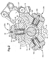
- the pump assembly is further provided with an inlet metering valve 37 (as shown in Figure 2 , but not visible in Figures 1 and 3 ) which supplies fuel at relatively low pressure, typically "transfer pressure", to each of the pump chambers 30.
- Inlet and outlet valve arrangements 40, 42 are provided for each pump chamber 30.
- the inlet and outlet valves 40, 42 for the first pump head 20a are visible in the section shown in Figure 3 and the inlet valve 40 of the first pump head 20a is also visible in the section view of Figure 2 (due to the position of the plunger 28).
- the inlet and outlet valves 40, 42 are located one on either side of the pump chamber 30 as this is beneficial in terms of pump size. Both the inlet and outlet valves 40, 42 therefore locate within fuel passages defined within the pump head 20a and, thus, within the same housing part of the pump assembly which guides tappet movement.
- the outlet valve 40 may take the form of a ball valve including a ball 41 which is engageable with a valve seating (not identified) to control whether fuel is delivered from the pump chamber 30 to a delivery passage 43 and, hence, to the common rail.
- the ball 41 is movable under hydraulic forces in dependence upon the pressure differential across it.
- the inlet metering valve 37 and the pump chamber inlet valve 40 control the supply of low pressure fuel delivery into the pump chamber 30. Primarily, it is the inlet metering valve 37 that controls the quantity of fuel delivered during each filing stage. Delivery of pressurised fuel out of the pump chamber 30 to the delivery passage 43 (as shown in Figure 3 ) and, hence, to the downstream common rail or accumulator volume, is controlled by the pump chamber outlet valve 42, as described previously.
- Pressurisation of fuel within the pump chamber 30 occurs during the pumping stroke of the associated plunger, during the period for which both the inlet and outlet valves 40, 42 are closed.
- fuel within the chamber 30 is pressurised to a level that is sufficient to open the outlet valve 42, pressurised fuel is supplied through the delivery passage 43 to the common rail.
- the pressure of fuel supplied through the outlet valve is in the range of between 1500 and 2000 bar.
- the outlet valve arrangement 40 shown in Figure 3 may alternatively be of the form shown in Figures 5 and 6 , in which the ball 41 is engageable with a valve seating 47 to control the flow of fuel between the pump chamber 30 and the common rail.
- the ball 41 is co-operable with an insert member or stop plug 46 which is received within the delivery passage 43 to limit the extent of opening movement of the ball 41.
- a compressible metal sealing washer 48 is located within an enlarged region of the passage 43 to provide a high pressure seal.
- the outer surface of the stop plug 46 is provided with four axially extending recesses, grooves or flutes 48, each of which defines, together with the internal surface of the delivery passage 43, a path for high pressure fuel flow to the common rail when the outlet valve 40 is open.
- the provision of the recesses 48 means that the stop plug 46 is generally of cruciform-like construction having two mutually orthogonal arms arranged in a cross-like configuration.
- the recesses 48 are equi-angularly spaced around the stop plug circumference to define four separate flow paths for high pressure fuel.
- a lower end of the stop plug 46 is tapered, or rounded, to define a smaller cross section than the upper portion of the stop plug 46.
- the outlet valve design in Figures 5 and 6 provides the benefit that the area for high pressure fuel flow through the open valve 40 is relatively large, without there being a requirement to provide drillings through a stop piece to define said flow paths, as is known in the art.
- inlet and outlet valves 40, 42 which may be used in the pump assembly can be found in our co-pending European patent application EP 1184568 A and British patent application GB 2384529 A .
- the pump assembly of the present invention is intended for use with a low pressure fuel pump, such as a transfer pump 44.
- the transfer pump 44 is mounted at the rear of the pump assembly for supplying fuel through the inlet metering valve and the inlet valves to their respective pump chambers 30. It is convenient to mount the transfer pump 44 upon the closure plate of the main pump housing 10, and to drive the transfer pump by means of a shaft extension in connection with the drive shaft 12.
- the main pump housing 10 is provided with an insert means within each of its radially extending openings 18a, 18b, 18c.
- the insert means may take the form of an insert member or sleeve of substantially cylindrical form which locates within its respective opening 18a, 18b, 18c, at its radially innermost end, so as to be substantially co-axially aligned with the plunger bore 26 and such that an end region of the extension 24 projects part way into the sleeve.
- a sleeve for guiding a tappet in a pump generally of the type described here is found in our co-pending patent application, GB 0308107.2 .
- the sleeve defines the axial guide surface for the tappet 34, instead of the internal surface of the opening 18a directly. This may provide the advantage that wear of the main pump housing 10 due to side loading of the tappets, is reduced. For this reason the requirement to form the main pump housing 10 from a hardened material, such as cast iron, is avoided, and only the sleeve need be formed so as to sustain the loading.
- the sleeve may be formed from hardened steel.
- the insert means may be provided by a steel coating which is applied to the internal surfaces of the openings 18a, 18b, 18c.
Description
- The invention relates to a pump assembly suitable for use in a common rail fuel injection system for supplying high pressure fuel to a compression ignition internal combustion engine. In particular, the invention relates to a pump assembly of the type having a cam rider mounted upon an engine driven cam and an intermediate drive member which is coupled to a pumping plunger and which co-operates with the cam rider, in use, so as to impart reciprocating, pumping motion to the plunger.
- In a known common rail fuel pump of radial pump design, three pumping plungers are arranged at equi-angularly spaced locations around an engine driven cam. Each plunger is mounted within a plunger bore provided in a main pump housing. As the cam is driven in use, the plungers are caused to reciprocate within their bores in a phased, cyclical manner. As the plungers reciprocate, each causes pressurisation of fuel within a pump chamber defined at one end of the associated plunger bore. The delivery of fuel from the pump chambers to a common high pressure supply line is controlled by means of delivery valves. The high pressure line supplies fuel to a common rail, or other accumulator volume, for delivery to the downstream injectors of the common rail fuel system.
- The cam carries a cam rider which extends co-axially with the drive shaft and is provided with a plurality of flats, one for each of the plungers. An intermediate drive member in the form of a tappet co-operates with the flat on the cam rider and couples to the plunger so that, as the tappet is driven upon rotation of the cam, drive is imparted to the plunger.
- It is important in pumps of this type that movement of both the plunger and of the tappet is guided as the parts are driven. However, from a manufacturing point of view, this is difficult to achieve in a pump assembly in which the main pump housing defines the guide path for both parts.
- It is with a view to addressing this incompatibility that we provide a fuel pump assembly of improved construction.
- A common rail fuel pump of radial pump design is described in
US Patent No. 6250893 . This pump has an eccentrically driven shaft supported in a pump housing, around which a ring with three flat faces is disposed to impart drive to three radially mounted pistons. These pistons are disposed in cylinder chambers and are reciprocated by the motion of the drive shaft. A tappet is mounted around each cylinder, the tappet being guided in a bore of the main pump housing. Each cylinder chamber is mounted between the main pump housing and a composite head part containing an inlet and an outlet valve. - According to the present invention, there is provided a pump assembly for use in delivering fuel to a common rail of an internal combustion engine, the pump assembly comprising: a pumping plunger, an intermediate drive member and an engine-driven cam, wherein the pumping plunger is co-operable with the intermediate drive member, and the intermediate drive member is further co-operable with the engine-drive cam, in use, so as to impart drive to the pumping plunger. The pump assembly further comprisesa cam rider member having an inner surface which is co-operable with the cam and an outer surface which is co-operable with the intermediate drive member, a main pump housing provided with a radially extending opening within which is received, at a first end thereof, a separate pump head and, at a second end thereof, the intermediate drive member so that the main pump housing serves to guide movement of the intermediate drive member, in use, characterised in that the separate pump head is an integral unit having a head portion and an extension which projects into the radially extending opening and which defines a plunger bore, which serves to guide movement of the pumping plunger, the extension providing an increased sealing length for the pumping plunger, and wherein the head portion defines a blind end of the plunger bore which, together with a radially outer face of the pumping plunger, defines a pump chamber in which fuel is pressurised as the pumping plunger is driven..
- In one preferred embodiment of the invention, the pump assembly comprises first, second and third plungers which are equi-angularly spaced around the engine drive cam, the cam rider member being provided with first, second and third surfaces for co-operation with first, second and third intermediate drive members, respectively, each intermediate drive member being coupled to an associated one of the plungers and wherein each of the intermediate drive members is guided within a respective one of first, second or third radially extending openings provided in the main pump housing, each of the first, second and third plungers being guided within a respective one of first, second or third plunger bores provided within a respective one of first, second or third pump heads mounted upon the main pump housing.
- This preferred embodiment of the pump assembly may therefore be considered as having three pump 'units' radially spaced around the cam, each pump unit having a pump head and a plunger coupled to an intermediate drive member for mounting within a radially extending opening in the main pump housing. The radially extending opening defines a chamber which is flooded with fuel and within which the intermediate drive member reciprocates, in use.
- It will be appreciated that the pump assembly of this preferred embodiment of the invention is not limited to having three pump units, and a greater number of pump units may be provided, if required.
- Preferably, the intermediate drive member takes the form of a tappet, typically a bucket-shaped tappet, having facing tappet sidewalls and a tappet base, wherein the tappet side walls are guided within the main pump housing and the tappet base co-operates with a flat on the outer surface of the cam rider member. It is further preferable to provide the pump assembly with means for allowing fuel to be displaced from, and supplied to, the chamber defined by the radially extending opening in the main pump housing. For example, each tappet sidewall may be provided with a sidewall opening in the form of a window to allow fuel to flow into the chamber and around the tappet during the plunger return stroke, and also to allow fuel to be displaced from the chamber during the plunger pumping stroke.
- The pump assembly has several benefits over known pump assemblies. As each plunger is guided within a separate pump head (i.e. a housing part separate from the other pump heads), and each tappet is guided within the main pump housing which is separate from the pump heads, the guidance bores are much easier to machine than in an assembly in which the plunger and the tappet are both guided within the main pump housing. This may pose another problem as any misalignment or 'tilt' of the pump heads relative to the main pump housing can lead to off-axis side loading of the plungers and/or tappets, resulting in an undesirable degree of wear. With this in mind, it is a preferable feature of the invention that the tappets are guided within the main pump housing, which is that part of the pump assembly carrying and locating both the drive shaft and the cam rider member.
- A benefit is also provided over other known pumps in which each tappet is provided with a roller which co-operates with the outer surface of the cam. The benefit is achieved as the requirement for individual rollers for each tappet is avoided by the use of the single cam rider which drives all three plungers and tappets.
- In use, as the cam is rotated by the drive shaft, the cam rider is caused to ride over the cam surface. The flat, or flattened region, of the surface of the cam rider member co-operates with the base of the tappet with the result that the tappet is driven axially, radially outward from the cam shaft, whilst a degree of relative sliding movement between the rider flat and the tappet occurs in a lateral direction (as the cam rider is able to slide relative to the axially guided tappet).
- Preferably, the main pump housing is provided with an axially extending opening for receiving the drive shaft. In a three plunger pump, each of first, second and third radially extending openings communicate, at respective inner ends thereof, with the axially extending opening in the main pump housing. The cam rider preferable takes the form of a generally tubular member arranged co-axially with the drive shaft.
- In one embodiment, the main pump housing includes an insert means which defines a guide path for the tappet. For example, an insert member may be received within the inner end of each of the first, second and third radially extending openings so that each insert member defines a guide path for a respective one of the tappets. The insert member may be of generally cylindrical form such that it takes the form of a sleeve. Preferably, the plunger bore and the insert member are substantially co-axially aligned.
- The insert means may alternatively take the form of a hardened coating e.g. a steel coating. This is particularly advantageous if the main pump housing is to be formed from cast iron, which is convenient and relatively light, as the hardness of the steel insert means (e.g. sleeve member or coating) avoids wear of the main pump housing.
- Alternatively, an internal surface of the radially extending opening may define the guide path for the tappet.
- As is described above, each pump head is provided with an extension which projects into the respective radially extending opening to define an increased plunger sealing length. This has the benefit of improving pump efficiency as losses due to leakage are reduced.
- The pump chamber of each pump unit has an outlet valve arrangement including a valve member which is engageable with a valve seating to open and close communication between the pump chamber and the common rail, whereby opening movement of the valve member is limited by means of a stop plug which defines at least two flow paths for fuel.
- Preferably, the stop plug has an outer surface provided with at least two axially extending recesses to define a flow path for high pressure fuel. An outlet valve of this construction is particularly convenient to manufacture.
- The advantageous features of the present invention are applicable not only to a pump assembly having three pump units (i.e. three plungers) but also to pump assemblies having just two pump units. In another preferred embodiment, therefore, the pump assembly may include only first and second pump units.
- In other words, the pump assembly may comprise a first plunger which is reciprocable within a first plunger bore provided in a first pump head and co-operable with a first intermediate drive member which is reciprocable within a first radially extending opening provided in the main pump housing, the pump assembly further comprising a second plunger which is reciprocable within a second plunger bore provided in a second pump head and co-operable with a second intermediate drive member which is reciprocable within a second radially extending opening provided in the main pump housing, wherein the first and second pump heads are received within a respective one of the first and second radially extending openings, at radially outermost ends thereof, said openings being located substantially diametrically opposite one another within the main pump housing.
- The present invention will now be described, by way of example only, with reference to the accompanying drawings in which:
-
Figure 1 is a perspective view of the pump assembly of the present invention, -
Figure 2 is a sectional view, from the rear, of the pump assembly inFigure 1 , -
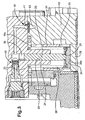
Figure 3 is a sectional view of a pump head component of the pump assembly inFigures 1 and2 , to show inlet and outlet valves for an associated pump chamber, -
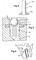
Figure 4 is a schematic view of an alternative plunger to that shown inFigures 1 to 3 , and -
Figures 5 and 6 show enlarged views of one type of outlet valve arrangement for use in the pump assembly ofFigures 1 to 3 . - Referring to
Figures 1 to 3 , a pump assembly includes a first housing part in the form of amain pump housing 10 provided with an axially extending opening 17. Acam drive shaft 12 is mounted within, and extends through, the axially extending opening 17 when the assembly is installed in the engine within which it is to be used. In the section shown inFigure 2 , thecentral axis 13 of thedrive shaft 12 is identified, although the drive shaft itself is not visible in this view. - The
drive shaft 12 co-operates with a cam arrangement including an eccentrically mountedcam 11. The main pump housing 10 projects, at its front end, to accommodate the near full length of thedrive shaft 12. The assembly is closed at its back end by a rear closure plate (not visible in the drawings) and at its front end by afront closure plate 15 having three ears orflanges 16, each provided with arespective opening 14 for receiving a suitable fixing for mounting the pump assembly to the engine. Thefront closure plate 15 has an rearwardly directed nose (not visible) which projects into themain pump housing 10. - The
main pump housing 10 is typically formed from cast iron and is provided with first, second and third radially extending openings or throughbores axially extending opening 17 through thehousing 10. A radially outer end of eachopening numerals pump head first pump head 20a will be described in detail below. - The
first pump head 20a includes ahead portion 22 and a downwardly extending extension 24 (in the orientation shown) which projects into a radially outer end of theopening 18a in themain pump housing 10. Theextension 24 is provided with a plunger bore 26 within which apumping plunger 28 is received. A blind end of the plunger bore 26 is located within thehead portion 22 of thefirst pump head 20a. The blind end of the plunger bore 26 defines, together with a radially outer end face of theplunger 28, apump chamber 30 to which fuel at relatively low pressure is delivered and within which pressurisation of fuel to a relatively high level suitable for injection takes place as theplunger 28 is driven to perform a pumping stroke, in use, upon rotation of thedrive shaft 12. - It is one benefit of this arrangement that the
extension 24 of thepump head 22 provides an increased sealing length for the plunger bore 26, which tends to reduce high pressure fuel leakage from thechamber 30. - A radially inner end of the
radially extending opening 18a receives an intermediate drive member for theplunger 28 in the form of atappet 34. The tappet is of U-shaped or channelled cross section, having first and second opposing sidewalls interconnected by a tappet base. Because of its construction, the tappet may be referred to as a "bucket tappet". Thetappet 34 locates within a radially inner end of theopening 18a so that an internal surface of theopening 18a serves to guide axial movement of thetappet 34, in use. It is therefore themain pump housing 10 which defines the guide surface for axial tappet motion and which constrains lateral tappet motion across thecam rider 38. - The
bucket tappet 34 is coupled to theplunger 28 by means of acirclip 29, as shown inFigure 3 . In practice, other coupling means may be provided for connecting thetappet 34 and theplunger 28 together, providing that the coupling is such that motion of one (e.g. the tappet) results in motion of the other (e.g. the plunger) during at least a part of the plunger's stroke. For example, thetappet 34 and theplunger 28 may be coupled together so that a degree of relative movement between them, along the main plunger axis, is permitted. - The upper surface of the tappet base is provided with recess for locating one end of a
plunger return spring 36. Thespring 36 is mounted concentrically with both theplunger 28 and theextension 24 and occupies a clearance region or chamber defined between the internal surface of theopening 18a and theextension 24. The other end of theplunger return spring 36 abuts thehead portion 22 of thefirst pump head 20a so that thespring 36 serves to apply a return biasing force to theplunger 28, and hence to thetappet 34, to drive a plunger return stroke. - The
drive shaft 12 co-operates with thecam 11 which, in turn, is co-operable with a generally tubularcam rider member 38 which extends co-axially with theshaft 12. On its outer surface thecam rider 38 is provided with first, second and third flattenedsurfaces flats tappet 34 for a respective one of theplungers 28. For example, thetappet 34 for theplunger 28 of thefirst pump head 20a co-operates with the first flat 38a on thecam rider 38. As thetappet 34 is coupled to theplunger 28, rotation of theshaft 12 causes thecam rider 38 to ride over the surface of thecam 11, thereby imparting drive to both thetappet 34 and theplunger 28. As thetappet 34 is driven, a degree of lateral sliding movement is permitted between the lower surface of the tappet base and the first flat 38a of therider 38 as thecam rider 38 is able to translate relative to the axially guidedtappet 34. A lubricating fluid, such as fuel, is provided between these sliding surfaces to limit wear due to friction. - As the
cam 11 is driven, thetappet 34 is caused to reciprocate within theopening 18a and theplunger 28 is caused to reciprocate within the plunger bore 26. Thetappet 34 and the pumpingplunger 28 are therefore driven together causing theplunger 28 to perform a pumping cycle including a pumping stroke, during which thetappet 34 and theplunger 28 are driven radially outward from the shaft (i.e. for thefirst pump head 20a, vertically upwards inFigures 1 to 3 ) to reduce the volume of thepump chamber 30. During this pumping stroke the pumpingplunger 28 is driven inwardly within its plunger bore 26 and fuel within thepump chamber 30 is pressurised to a relatively high level in a manner which would be familiar to those skilled in this technology field. - During a subsequent plunger return stroke, the
tappet 34 and theplunger 28 are urged in a radially inward direction (i.e. for thefirst pump head 20a, vertically downwards inFigures 1 to 3 ) to increase the volume of thepump chamber 30. During the return stroke of theplunger 28 and itstappet 34, theplunger 28 is urged outwardly from the plunger bore 26 and fuel at relatively low pressure fills the associatedpump chamber 30. - The provision of the
plunger return spring 36 serves to urge theplunger 28 to perform its return stroke and additionally ensures contact is maintained between thetappet 34 and the flat 38a of therider 38 at all times throughout the pumping cycle. - The
tappet 34 and theplunger 28 perform cyclical sinusoidal motion and are driven at a maximum frequency of about 120 Hz. Thetappet 34 typically has a range of travel, between bottom-dead-centre and top-dead-centre, of around 10 millimetres. - It is a particular feature of the pump assembly of the present invention that plunger movement is guided by the
pump head 18a (i.e. within the plunger bore 26), whereas tappet moment is guided by the main pump housing 10 (i.e. within theradially extending opening 18a). The side walls of thetappet 34 have outer surfaces of generally cylindrical form, and it is these outer surfaces which cooperate with a substantially cylindrical internal surface of theopening 18a such that motion of thetappet 34 is guided as it reciprocates. By guiding movement of theplunger 28 within a separate part of the pump (i.e.pump head 18a) to themain pump housing 10 which guides the tappet, a manufacturing advantage is achieved as alignment between theopenings - Problems of tilt between the pump heads 18a, 18b, 18c and the
main pump housing 10 are avoided as the guide surface for thetappet 34 is defined by the same housing (i.e. the main pump housing) which supports and locates thedrive shaft 12 and thecam rider 38. Tilt problems may otherwise arise, for example, if surface to surface contact between thehead portion 22 of the pump head and themain pump housing 10 is not exactly flat. - The
main pump housing 10 is machined so as to minimise geometric deviations which would affect the ability of the flat 'sliding' surface of the tappet base to be properly in contact with the corresponding flat 38a on thecam rider 38. Deviations possibly arise due to the need for accurate perpendicularity between the axis of theopening openings main pump housing 10 also supports the shaft bearings as precisely as is practical. The rear bearing is fitted directly into themain housing 10, while the front bearing is in thefront closure plate 15. Themain pump housing 10 locates thefront closure plate 15 so that the front and rear bearings are substantially concentric. All the relevant features (e.g. theradially extending openings front closure plate 15 for the front bearing, the diameter of the inner nose of the front closure plate 15) are all machined precisely, both in size and relative position. Having the critical features mostly in a single part (i.e. the main pump housing 10) enables errors to be minimised by machining dependent features so that the predominant feature is used as a datum or reference. In this case, the reference is the bore for the rear bearing in themain pump housing 10. This is helped further by minimising the number of times that themain pump housing 10 needs to be mounted in a machine tool during manufacture (preferably only once). - It is another feature of the
tappet 34 in the present invention that windows orsidewall openings 35 are formed in the sidewalls to provide a means for allowing fuel to flow into and out of the clearance region, or chamber, defined within theopening 18a. As thetappet 34 andplunger 28 are driven through the pumping stroke, fuel is dispelled from the clearance region through thewindows 35. As thetappet 34 andplunger 28 perform the return stroke, fuel is drawn into the clearance region through thewindows 35. -
Figure 4 shows analternative plunger 128 to that shown inFigures 1 to 3 . InFigure 4 , theplunger 128 is formed in two parts; amain plunger body 128a and aplunger base 128b. Theplunger base 128b forms an interference fit with the lower end of theplunger body 128a and defines a platform for a washer (not shown) or other abutment piece against which the plunger return spring sits. The two-part construction of theplunger 128 is beneficial as machining of the uniformdiameter plunger body 128a is relatively easy to achieve and material wastage during machining is minimised. - Referring again to
Figures 1 to 3 , the pump assembly is further provided with an inlet metering valve 37 (as shown inFigure 2 , but not visible inFigures 1 and3 ) which supplies fuel at relatively low pressure, typically "transfer pressure", to each of thepump chambers 30. Inlet andoutlet valve arrangements pump chamber 30. The inlet andoutlet valves first pump head 20a are visible in the section shown inFigure 3 and theinlet valve 40 of thefirst pump head 20a is also visible in the section view ofFigure 2 (due to the position of the plunger 28). The inlet andoutlet valves pump chamber 30 as this is beneficial in terms of pump size. Both the inlet andoutlet valves pump head 20a and, thus, within the same housing part of the pump assembly which guides tappet movement. - The
outlet valve 40 may take the form of a ball valve including aball 41 which is engageable with a valve seating (not identified) to control whether fuel is delivered from thepump chamber 30 to adelivery passage 43 and, hence, to the common rail. Theball 41 is movable under hydraulic forces in dependence upon the pressure differential across it. - The
inlet metering valve 37 and the pumpchamber inlet valve 40 control the supply of low pressure fuel delivery into thepump chamber 30. Primarily, it is theinlet metering valve 37 that controls the quantity of fuel delivered during each filing stage. Delivery of pressurised fuel out of thepump chamber 30 to the delivery passage 43 (as shown inFigure 3 ) and, hence, to the downstream common rail or accumulator volume, is controlled by the pumpchamber outlet valve 42, as described previously. - Pressurisation of fuel within the
pump chamber 30 occurs during the pumping stroke of the associated plunger, during the period for which both the inlet andoutlet valves chamber 30 is pressurised to a level that is sufficient to open theoutlet valve 42, pressurised fuel is supplied through thedelivery passage 43 to the common rail. Typically, the pressure of fuel supplied through the outlet valve is in the range of between 1500 and 2000 bar. - During the return stroke of the
plunger 28, fuel pressure downstream of thepump chamber 30 is higher than that within thepump chamber 30 and the outlet valve is urged closed. During the period of the return stroke for which theinlet valve 40 is urged open, fuel at relatively low pressure is supplied to thepump chamber 30 ready for commencement of the following pumping stroke. This cycle of pumping is described in further detail in the aforementioned patent applications, and in any case would be familiar to those skilled in this field. - The
outlet valve arrangement 40 shown inFigure 3 may alternatively be of the form shown inFigures 5 and 6 , in which theball 41 is engageable with avalve seating 47 to control the flow of fuel between thepump chamber 30 and the common rail. Theball 41 is co-operable with an insert member or stopplug 46 which is received within thedelivery passage 43 to limit the extent of opening movement of theball 41. A compressiblemetal sealing washer 48 is located within an enlarged region of thepassage 43 to provide a high pressure seal. - The outer surface of the
stop plug 46 is provided with four axially extending recesses, grooves orflutes 48, each of which defines, together with the internal surface of thedelivery passage 43, a path for high pressure fuel flow to the common rail when theoutlet valve 40 is open. The provision of therecesses 48 means that thestop plug 46 is generally of cruciform-like construction having two mutually orthogonal arms arranged in a cross-like configuration. Therecesses 48 are equi-angularly spaced around the stop plug circumference to define four separate flow paths for high pressure fuel. A lower end of thestop plug 46 is tapered, or rounded, to define a smaller cross section than the upper portion of thestop plug 46. The outlet valve design inFigures 5 and 6 provides the benefit that the area for high pressure fuel flow through theopen valve 40 is relatively large, without there being a requirement to provide drillings through a stop piece to define said flow paths, as is known in the art. - Examples of other inlet and
outlet valves EP 1184568 A and British patent applicationGB 2384529 A - The pump assembly of the present invention is intended for use with a low pressure fuel pump, such as a
transfer pump 44. Thetransfer pump 44 is mounted at the rear of the pump assembly for supplying fuel through the inlet metering valve and the inlet valves to theirrespective pump chambers 30. It is convenient to mount thetransfer pump 44 upon the closure plate of themain pump housing 10, and to drive the transfer pump by means of a shaft extension in connection with thedrive shaft 12. - In a further alternative embodiment of the pump assembly (not shown), the
main pump housing 10 is provided with an insert means within each of itsradially extending openings respective opening extension 24 projects part way into the sleeve. A sleeve for guiding a tappet in a pump generally of the type described here is found in our co-pending patent application,GB 0308107.2 tappet 34, instead of the internal surface of theopening 18a directly. This may provide the advantage that wear of themain pump housing 10 due to side loading of the tappets, is reduced. For this reason the requirement to form themain pump housing 10 from a hardened material, such as cast iron, is avoided, and only the sleeve need be formed so as to sustain the loading. Typically, for example, the sleeve may be formed from hardened steel. - Alternatively, the insert means may be provided by a steel coating which is applied to the internal surfaces of the
openings
Claims (14)
- A pump assembly for use in delivering fuel to a common rail of an internal combustion engine, the pump assembly comprising:a pumping plunger (28; 128), an intermediate drive member (34) and an engine-driven cam (11), wherein the pumping plunger (28; 128) is co-operable with the intermediate drive member (34), and the intermediate drive member (34) is further co-operable with the engine-drive cam (11), in use, so as to impart drive to the pumping plunger (28; 128),a cam rider member (38) having an inner surface which is co-operable with the cam (11) and an outer surface which is co-operable with the intermediate drive member (34),a main pump housing (10) provided with a radially extending opening (18a) within which is received, at a first end thereof, a separate pump head (20a) and, at a second end thereof, the intermediate drive member (34) so that the main pump housing (10) serves to guide movement of the intermediate drive member (34), in use,characterised in that the separate pump head (20a) is an integral unit having a head portion and an extension (24) which projects into the radially extending opening (18a, 18b, 18c) and which defines a plunger bore (26), which serves to guide movement of the pumping plunger (28; 128), the extension providing an increased sealing length for the pumping plunger, and wherein the head portion defines a blind end of the plunger bore which, together with a radially outer face of the pumping plunger (28; 128), defines a pump chamber (30) in which fuel is pressurised as the pumping plunger (28; 128) is driven.
- The pump assembly as claimed in claim 1, wherein the main pump housing (10) is provided with an axially extending opening (17) for receiving an engine drive shaft (12), in use, and wherein an innermost end of the radially extending opening (18a) opens into the axially extending opening (17).
- The pump assembly as claimed in claim 1 or claim 2, the pump assembly comprising first, second and third pump units (20a, 20b, 20c) equi-angularly spaced around the cam (11), each of the first, second and third pump units (20a, 20b, 20c) including a pumping plunger (28) and an intermediate drive member (34) which is received within a respective one of a first, second or third radially extending opening (18a, 18b, 18c) provided in the main pump housing (10).
- The pump assembly as claimed in claim 1 or claim 2, the pump assembly comprising first and second pump units (20a, 20b) only, each of the first and second pump units including a pumping plunger (28) and an intermediate drive member (34) which is received within a respective one of a first or second radially extending opening provided in the main pump housing (10), the first and second radially extending openings being arranged substantially diametrically opposite one another.
- The pump assembly as claimed in any one of claims 1 to 4, wherein the intermediate drive member takes the form of a tappet (34) having opposed tappet sidewalls and a tappet base, wherein the tappet side walls are guided within the radially extending opening (18a) in the main pump housing (10) and the tappet base co-operates with a flat (38a) on the outer surface of the cam rider member (38).
- The pump assembly as claimed in claim 5, further comprising means (35) for allowing fuel to be displaced from, and supplied to, the radially extending opening (18a) in the main pump housing (10) as the tappet (34) reciprocates, in use.
- The pump assembly as claimed in claim 6, wherein said means for allowing fuel to be displaced from, and supplied to, the radially extending opening (18a) includes a sidewall opening (35) provided in the tappet sidewall.
- The pump assembly as claimed in any one of claims 1 to 7, wherein the main pump housing (10) includes an insert means which defines a guide path for the intermediate drive member (34).
- The pump assembly as claimed in claim 8, wherein the insert means is one of an insert sleeve of generally cylindrical form or a coating applied to an internal surface of the opening (18a, 18b, 18c).
- The pump assembly as claimed in claim 9, wherein the plunger bore and the insert member are substantially co-axially aligned.
- The pump assembly as claimed in any one of claims 1 to 7, wherein an internal surface of the radially extending opening (18a, 18b, 18c) defines the guide path for the intermediate drive member (34).
- The pump assembly as claimed in any one of claims 1 to 11, wherein the pump chamber (30) has an outlet valve arrangement including a valve member (41) which is engageable with a valve seating (47) to open and close communication between the pump chamber (30) and the common rail, wherein opening movement of the valve member (41) is limited by means of a stop plug (46) which defines, at least in part, at least two flow paths for fuel.
- The pump assembly as claimed in claim 12, wherein the stop plug (46) has an outer surface provided with at least two axially extending recesses to define a flow path for high pressure fuel.
- The pump assembly as claimed in claim 13, wherein the stop plug (46) has an outer surface provided with four axially extending recesses, equi-angularly spaced around the outer surface of the stop plug, to define four separate flow paths for high pressure fuel.
Applications Claiming Priority (2)
| Application Number | Priority Date | Filing Date | Title |
|---|---|---|---|
| GBGB0311814.8A GB0311814D0 (en) | 2003-05-22 | 2003-05-22 | Pump assembly |
| PCT/GB2004/002235 WO2004104409A1 (en) | 2003-05-22 | 2004-05-24 | Pump assembly |
Publications (2)
| Publication Number | Publication Date |
|---|---|
| EP1629191A1 EP1629191A1 (en) | 2006-03-01 |
| EP1629191B1 true EP1629191B1 (en) | 2014-04-23 |
Family
ID=9958600
Family Applications (1)
| Application Number | Title | Priority Date | Filing Date |
|---|---|---|---|
| EP04734539.2A Active EP1629191B1 (en) | 2003-05-22 | 2004-05-24 | Pump assembly |
Country Status (6)
| Country | Link |
|---|---|
| US (1) | US20070041848A1 (en) |
| EP (1) | EP1629191B1 (en) |
| JP (1) | JP2007500312A (en) |
| ES (1) | ES2466247T3 (en) |
| GB (1) | GB0311814D0 (en) |
| WO (1) | WO2004104409A1 (en) |
Families Citing this family (38)
| Publication number | Priority date | Publication date | Assignee | Title |
|---|---|---|---|---|
| EP2113653A1 (en) | 2008-04-30 | 2009-11-04 | Delphi Technologies, Inc. | Fluid Pump |
| EP2184491A1 (en) | 2008-11-07 | 2010-05-12 | Delphi Technologies Holding S.à.r.l. | Pump head for fuel pump assembly |
| EP2189658B1 (en) | 2008-11-24 | 2017-11-22 | Delphi International Operations Luxembourg S.à r.l. | Fluid Pump Assembly |
| EP2278163A1 (en) | 2009-07-20 | 2011-01-26 | Delphi Technologies Holding S.à.r.l. | Pump assembly |
| GB201012634D0 (en) * | 2010-07-28 | 2010-09-15 | Delphi Technologies Holding | Intermediate drive assembly |
| US9567960B2 (en) * | 2014-03-25 | 2017-02-14 | Cummins Inc. | Fuel pump tappet assembly |
| CN105584661A (en) * | 2016-02-24 | 2016-05-18 | 浙江章氏护栏科技有限公司 | Discharging and packaging device of plastic edge sealing strip |
| IT201600132423A1 (en) * | 2016-12-29 | 2018-06-29 | Bosch Gmbh Robert | HYBRID PROPULSION SYSTEM FOR VEHICLES |
| US11624326B2 (en) | 2017-05-21 | 2023-04-11 | Bj Energy Solutions, Llc | Methods and systems for supplying fuel to gas turbine engines |
| US11560845B2 (en) | 2019-05-15 | 2023-01-24 | Bj Energy Solutions, Llc | Mobile gas turbine inlet air conditioning system and associated methods |
| CA3197583A1 (en) | 2019-09-13 | 2021-03-13 | Bj Energy Solutions, Llc | Fuel, communications, and power connection systems and related methods |
| US11015594B2 (en) | 2019-09-13 | 2021-05-25 | Bj Energy Solutions, Llc | Systems and method for use of single mass flywheel alongside torsional vibration damper assembly for single acting reciprocating pump |
| US11002189B2 (en) | 2019-09-13 | 2021-05-11 | Bj Energy Solutions, Llc | Mobile gas turbine inlet air conditioning system and associated methods |
| US10961914B1 (en) | 2019-09-13 | 2021-03-30 | BJ Energy Solutions, LLC Houston | Turbine engine exhaust duct system and methods for noise dampening and attenuation |
| US11555756B2 (en) | 2019-09-13 | 2023-01-17 | Bj Energy Solutions, Llc | Fuel, communications, and power connection systems and related methods |
| US10895202B1 (en) | 2019-09-13 | 2021-01-19 | Bj Energy Solutions, Llc | Direct drive unit removal system and associated methods |
| CA3092829C (en) | 2019-09-13 | 2023-08-15 | Bj Energy Solutions, Llc | Methods and systems for supplying fuel to gas turbine engines |
| CA3092865C (en) | 2019-09-13 | 2023-07-04 | Bj Energy Solutions, Llc | Power sources and transmission networks for auxiliary equipment onboard hydraulic fracturing units and associated methods |
| US10815764B1 (en) | 2019-09-13 | 2020-10-27 | Bj Energy Solutions, Llc | Methods and systems for operating a fleet of pumps |
| US11708829B2 (en) | 2020-05-12 | 2023-07-25 | Bj Energy Solutions, Llc | Cover for fluid systems and related methods |
| US10968837B1 (en) | 2020-05-14 | 2021-04-06 | Bj Energy Solutions, Llc | Systems and methods utilizing turbine compressor discharge for hydrostatic manifold purge |
| US11428165B2 (en) | 2020-05-15 | 2022-08-30 | Bj Energy Solutions, Llc | Onboard heater of auxiliary systems using exhaust gases and associated methods |
| US11208880B2 (en) | 2020-05-28 | 2021-12-28 | Bj Energy Solutions, Llc | Bi-fuel reciprocating engine to power direct drive turbine fracturing pumps onboard auxiliary systems and related methods |
| US11208953B1 (en) | 2020-06-05 | 2021-12-28 | Bj Energy Solutions, Llc | Systems and methods to enhance intake air flow to a gas turbine engine of a hydraulic fracturing unit |
| US11109508B1 (en) | 2020-06-05 | 2021-08-31 | Bj Energy Solutions, Llc | Enclosure assembly for enhanced cooling of direct drive unit and related methods |
| US11111768B1 (en) | 2020-06-09 | 2021-09-07 | Bj Energy Solutions, Llc | Drive equipment and methods for mobile fracturing transportation platforms |
| US10954770B1 (en) | 2020-06-09 | 2021-03-23 | Bj Energy Solutions, Llc | Systems and methods for exchanging fracturing components of a hydraulic fracturing unit |
| US11066915B1 (en) | 2020-06-09 | 2021-07-20 | Bj Energy Solutions, Llc | Methods for detection and mitigation of well screen out |
| US11028677B1 (en) | 2020-06-22 | 2021-06-08 | Bj Energy Solutions, Llc | Stage profiles for operations of hydraulic systems and associated methods |
| US11125066B1 (en) | 2020-06-22 | 2021-09-21 | Bj Energy Solutions, Llc | Systems and methods to operate a dual-shaft gas turbine engine for hydraulic fracturing |
| US11939853B2 (en) | 2020-06-22 | 2024-03-26 | Bj Energy Solutions, Llc | Systems and methods providing a configurable staged rate increase function to operate hydraulic fracturing units |
| US11933153B2 (en) | 2020-06-22 | 2024-03-19 | Bj Energy Solutions, Llc | Systems and methods to operate hydraulic fracturing units using automatic flow rate and/or pressure control |
| US11473413B2 (en) | 2020-06-23 | 2022-10-18 | Bj Energy Solutions, Llc | Systems and methods to autonomously operate hydraulic fracturing units |
| US11466680B2 (en) | 2020-06-23 | 2022-10-11 | Bj Energy Solutions, Llc | Systems and methods of utilization of a hydraulic fracturing unit profile to operate hydraulic fracturing units |
| US11220895B1 (en) | 2020-06-24 | 2022-01-11 | Bj Energy Solutions, Llc | Automated diagnostics of electronic instrumentation in a system for fracturing a well and associated methods |
| US11149533B1 (en) | 2020-06-24 | 2021-10-19 | Bj Energy Solutions, Llc | Systems to monitor, detect, and/or intervene relative to cavitation and pulsation events during a hydraulic fracturing operation |
| US11193360B1 (en) | 2020-07-17 | 2021-12-07 | Bj Energy Solutions, Llc | Methods, systems, and devices to enhance fracturing fluid delivery to subsurface formations during high-pressure fracturing operations |
| US11639654B2 (en) * | 2021-05-24 | 2023-05-02 | Bj Energy Solutions, Llc | Hydraulic fracturing pumps to enhance flow of fracturing fluid into wellheads and related methods |
Family Cites Families (11)
| Publication number | Priority date | Publication date | Assignee | Title |
|---|---|---|---|---|
| DE4227853C2 (en) * | 1992-08-22 | 1996-05-30 | Bosch Gmbh Robert | Fuel injection pump for internal combustion engines |
| US5382140A (en) * | 1993-02-11 | 1995-01-17 | Elasis Sistema Ricerca Fiat Nel Mezzogiorno | Radial-piston pump |
| DE19729790C2 (en) * | 1997-07-11 | 2002-08-29 | Bosch Gmbh Robert | Radial piston pump for high-pressure fuel supply |
| DE19729788A1 (en) * | 1997-07-11 | 1999-01-14 | Bosch Gmbh Robert | Radial piston pump for high-pressure fuel supply |
| DE19753593A1 (en) * | 1997-12-03 | 1999-06-17 | Bosch Gmbh Robert | Radial piston pump for high-pressure fuel supply |
| EP0979353B1 (en) * | 1998-02-27 | 2004-09-29 | Stanadyne Corporation | Supply pump for gasoline common rail |
| DE19814506A1 (en) * | 1998-04-01 | 1999-10-14 | Bosch Gmbh Robert | Radial piston pump for high-pressure fuel supply |
| JP3852756B2 (en) * | 2001-02-07 | 2006-12-06 | 株式会社デンソー | Fuel injection pump |
| DE10117600C1 (en) * | 2001-04-07 | 2002-08-22 | Bosch Gmbh Robert | High-pressure fuel pump for a fuel system of a direct-injection internal combustion engine, fuel system and internal combustion engine |
| JP2003074439A (en) * | 2001-06-19 | 2003-03-12 | Denso Corp | Fuel injection pump |
| JP2003161227A (en) * | 2001-11-29 | 2003-06-06 | Denso Corp | Fuel injection pump and assembling method of its check valve device |
-
2003
- 2003-05-22 GB GBGB0311814.8A patent/GB0311814D0/en not_active Ceased
-
2004
- 2004-05-24 WO PCT/GB2004/002235 patent/WO2004104409A1/en active Application Filing
- 2004-05-24 US US10/558,180 patent/US20070041848A1/en not_active Abandoned
- 2004-05-24 ES ES04734539.2T patent/ES2466247T3/en active Active
- 2004-05-24 EP EP04734539.2A patent/EP1629191B1/en active Active
- 2004-05-24 JP JP2006530536A patent/JP2007500312A/en active Pending
Also Published As
| Publication number | Publication date |
|---|---|
| ES2466247T3 (en) | 2014-06-09 |
| JP2007500312A (en) | 2007-01-11 |
| GB0311814D0 (en) | 2003-06-25 |
| US20070041848A1 (en) | 2007-02-22 |
| WO2004104409A1 (en) | 2004-12-02 |
| EP1629191A1 (en) | 2006-03-01 |
Similar Documents
| Publication | Publication Date | Title |
|---|---|---|
| EP1629191B1 (en) | Pump assembly | |
| US5775203A (en) | High pressure fuel pump assembly | |
| US20100037865A1 (en) | Tappet assembly for a high-pressure pump and high-pressure pump comprising at least one tappet assembly | |
| KR101120709B1 (en) | High-pressure pump piston/cylinder unit | |
| US8272856B2 (en) | High-pressure pump, in particular for a fuel injection apparatus of an internal combustion engine | |
| EP2530315A1 (en) | Fuel pump lubrication | |
| EP1651863B1 (en) | Common rail fuel pump | |
| KR19990066798A (en) | High Pressure Fuel Supply Pump | |
| US8215925B2 (en) | Pump assembly and tappet therefor | |
| EP1413749B1 (en) | Fuel pump assembly | |
| GB2366336A (en) | Fuel pump | |
| KR0167112B1 (en) | Fuel distribution injection pump for internal combustion engine | |
| JP3945005B2 (en) | pump | |
| US4842496A (en) | Fuel injection pump for internal combustion engines including onset of supply control means | |
| US4840161A (en) | Fuel injection pump for internal combustion engines | |
| US7395815B2 (en) | Fuel injection pump | |
| EP2299114B1 (en) | Pump assembly | |
| EP3085944B1 (en) | Externally sprung tappet with head turret guide for a fuel pump | |
| EP1363016A2 (en) | Fuel pump | |
| JP2000145572A (en) | Fuel injection pump | |
| EP1705368B1 (en) | Fuel pump | |
| EP1489301B1 (en) | Drive arrangement for a pump | |
| EP3064759B1 (en) | High temperature fuel deflector for a fuel pump drive assembly | |
| GB2400418A (en) | Liner for a pump assembly | |
| WO2023287709A1 (en) | Fuel pump assembly |
Legal Events
| Date | Code | Title | Description |
|---|---|---|---|
| PUAI | Public reference made under article 153(3) epc to a published international application that has entered the european phase |
Free format text: ORIGINAL CODE: 0009012 |
|
| 17P | Request for examination filed |
Effective date: 20051220 |
|
| AK | Designated contracting states |
Kind code of ref document: A1 Designated state(s): AT BE BG CH CY CZ DE DK EE ES FI FR GB GR HU IE IT LI LU MC NL PL PT RO SE SI SK TR |
|
| DAX | Request for extension of the european patent (deleted) | ||
| 17Q | First examination report despatched |
Effective date: 20080908 |
|
| RAP1 | Party data changed (applicant data changed or rights of an application transferred) |
Owner name: DELPHI TECHNOLOGIES HOLDING S.A.R.L. |
|
| REG | Reference to a national code |
Ref country code: DE Ref legal event code: R079 Ref document number: 602004044901 Country of ref document: DE Free format text: PREVIOUS MAIN CLASS: F02M0063020000 Ipc: F04B0001040000 |
|
| RIC1 | Information provided on ipc code assigned before grant |
Ipc: F02M 63/00 20060101ALI20131010BHEP Ipc: F02M 63/02 20060101ALI20131010BHEP Ipc: F02M 59/10 20060101ALI20131010BHEP Ipc: F04B 1/04 20060101AFI20131010BHEP Ipc: F02M 59/46 20060101ALI20131010BHEP |
|
| GRAP | Despatch of communication of intention to grant a patent |
Free format text: ORIGINAL CODE: EPIDOSNIGR1 |
|
| INTG | Intention to grant announced |
Effective date: 20131217 |
|
| GRAS | Grant fee paid |
Free format text: ORIGINAL CODE: EPIDOSNIGR3 |
|
| RAP1 | Party data changed (applicant data changed or rights of an application transferred) |
Owner name: DELPHI INTERNATIONAL OPERATIONS LUXEMBOURG S.A.R.L |
|
| GRAA | (expected) grant |
Free format text: ORIGINAL CODE: 0009210 |
|
| AK | Designated contracting states |
Kind code of ref document: B1 Designated state(s): AT BE BG CH CY CZ DE DK EE ES FI FR GB GR HU IE IT LI LU MC NL PL PT RO SE SI SK TR |
|
| REG | Reference to a national code |
Ref country code: GB Ref legal event code: FG4D |
|
| REG | Reference to a national code |
Ref country code: CH Ref legal event code: EP |
|
| REG | Reference to a national code |
Ref country code: AT Ref legal event code: REF Ref document number: 664027 Country of ref document: AT Kind code of ref document: T Effective date: 20140515 |
|
| REG | Reference to a national code |
Ref country code: IE Ref legal event code: FG4D |
|
| REG | Reference to a national code |
Ref country code: DE Ref legal event code: R096 Ref document number: 602004044901 Country of ref document: DE Effective date: 20140605 |
|
| REG | Reference to a national code |
Ref country code: ES Ref legal event code: FG2A Ref document number: 2466247 Country of ref document: ES Kind code of ref document: T3 Effective date: 20140609 |
|
| REG | Reference to a national code |
Ref country code: AT Ref legal event code: MK05 Ref document number: 664027 Country of ref document: AT Kind code of ref document: T Effective date: 20140423 |
|
| REG | Reference to a national code |
Ref country code: NL Ref legal event code: VDEP Effective date: 20140423 |
|
| REG | Reference to a national code |
Ref country code: HU Ref legal event code: AG4A Ref document number: E020388 Country of ref document: HU |
|
| PG25 | Lapsed in a contracting state [announced via postgrant information from national office to epo] |
Ref country code: CY Free format text: LAPSE BECAUSE OF FAILURE TO SUBMIT A TRANSLATION OF THE DESCRIPTION OR TO PAY THE FEE WITHIN THE PRESCRIBED TIME-LIMIT Effective date: 20140423 Ref country code: FI Free format text: LAPSE BECAUSE OF FAILURE TO SUBMIT A TRANSLATION OF THE DESCRIPTION OR TO PAY THE FEE WITHIN THE PRESCRIBED TIME-LIMIT Effective date: 20140423 Ref country code: NL Free format text: LAPSE BECAUSE OF FAILURE TO SUBMIT A TRANSLATION OF THE DESCRIPTION OR TO PAY THE FEE WITHIN THE PRESCRIBED TIME-LIMIT Effective date: 20140423 Ref country code: BG Free format text: LAPSE BECAUSE OF FAILURE TO SUBMIT A TRANSLATION OF THE DESCRIPTION OR TO PAY THE FEE WITHIN THE PRESCRIBED TIME-LIMIT Effective date: 20140723 Ref country code: GR Free format text: LAPSE BECAUSE OF FAILURE TO SUBMIT A TRANSLATION OF THE DESCRIPTION OR TO PAY THE FEE WITHIN THE PRESCRIBED TIME-LIMIT Effective date: 20140724 |
|
| PG25 | Lapsed in a contracting state [announced via postgrant information from national office to epo] |
Ref country code: AT Free format text: LAPSE BECAUSE OF FAILURE TO SUBMIT A TRANSLATION OF THE DESCRIPTION OR TO PAY THE FEE WITHIN THE PRESCRIBED TIME-LIMIT Effective date: 20140423 Ref country code: PL Free format text: LAPSE BECAUSE OF FAILURE TO SUBMIT A TRANSLATION OF THE DESCRIPTION OR TO PAY THE FEE WITHIN THE PRESCRIBED TIME-LIMIT Effective date: 20140423 Ref country code: SE Free format text: LAPSE BECAUSE OF FAILURE TO SUBMIT A TRANSLATION OF THE DESCRIPTION OR TO PAY THE FEE WITHIN THE PRESCRIBED TIME-LIMIT Effective date: 20140423 |
|
| PG25 | Lapsed in a contracting state [announced via postgrant information from national office to epo] |
Ref country code: PT Free format text: LAPSE BECAUSE OF FAILURE TO SUBMIT A TRANSLATION OF THE DESCRIPTION OR TO PAY THE FEE WITHIN THE PRESCRIBED TIME-LIMIT Effective date: 20140825 |
|
| REG | Reference to a national code |
Ref country code: CH Ref legal event code: PL |
|
| REG | Reference to a national code |
Ref country code: DE Ref legal event code: R097 Ref document number: 602004044901 Country of ref document: DE |
|
| PG25 | Lapsed in a contracting state [announced via postgrant information from national office to epo] |
Ref country code: DK Free format text: LAPSE BECAUSE OF FAILURE TO SUBMIT A TRANSLATION OF THE DESCRIPTION OR TO PAY THE FEE WITHIN THE PRESCRIBED TIME-LIMIT Effective date: 20140423 Ref country code: SK Free format text: LAPSE BECAUSE OF FAILURE TO SUBMIT A TRANSLATION OF THE DESCRIPTION OR TO PAY THE FEE WITHIN THE PRESCRIBED TIME-LIMIT Effective date: 20140423 Ref country code: CZ Free format text: LAPSE BECAUSE OF FAILURE TO SUBMIT A TRANSLATION OF THE DESCRIPTION OR TO PAY THE FEE WITHIN THE PRESCRIBED TIME-LIMIT Effective date: 20140423 Ref country code: LI Free format text: LAPSE BECAUSE OF NON-PAYMENT OF DUE FEES Effective date: 20140531 Ref country code: MC Free format text: LAPSE BECAUSE OF FAILURE TO SUBMIT A TRANSLATION OF THE DESCRIPTION OR TO PAY THE FEE WITHIN THE PRESCRIBED TIME-LIMIT Effective date: 20140423 Ref country code: BE Free format text: LAPSE BECAUSE OF FAILURE TO SUBMIT A TRANSLATION OF THE DESCRIPTION OR TO PAY THE FEE WITHIN THE PRESCRIBED TIME-LIMIT Effective date: 20140423 Ref country code: RO Free format text: LAPSE BECAUSE OF FAILURE TO SUBMIT A TRANSLATION OF THE DESCRIPTION OR TO PAY THE FEE WITHIN THE PRESCRIBED TIME-LIMIT Effective date: 20140423 Ref country code: EE Free format text: LAPSE BECAUSE OF FAILURE TO SUBMIT A TRANSLATION OF THE DESCRIPTION OR TO PAY THE FEE WITHIN THE PRESCRIBED TIME-LIMIT Effective date: 20140423 Ref country code: CH Free format text: LAPSE BECAUSE OF NON-PAYMENT OF DUE FEES Effective date: 20140531 |
|
| REG | Reference to a national code |
Ref country code: IE Ref legal event code: MM4A |
|
| PLBE | No opposition filed within time limit |
Free format text: ORIGINAL CODE: 0009261 |
|
| STAA | Information on the status of an ep patent application or granted ep patent |
Free format text: STATUS: NO OPPOSITION FILED WITHIN TIME LIMIT |
|
| 26N | No opposition filed |
Effective date: 20150126 |
|
| PG25 | Lapsed in a contracting state [announced via postgrant information from national office to epo] |
Ref country code: IE Free format text: LAPSE BECAUSE OF NON-PAYMENT OF DUE FEES Effective date: 20140524 |
|
| REG | Reference to a national code |
Ref country code: DE Ref legal event code: R097 Ref document number: 602004044901 Country of ref document: DE Effective date: 20150126 |
|
| PG25 | Lapsed in a contracting state [announced via postgrant information from national office to epo] |
Ref country code: SI Free format text: LAPSE BECAUSE OF FAILURE TO SUBMIT A TRANSLATION OF THE DESCRIPTION OR TO PAY THE FEE WITHIN THE PRESCRIBED TIME-LIMIT Effective date: 20140423 |
|
| REG | Reference to a national code |
Ref country code: FR Ref legal event code: PLFP Year of fee payment: 13 |
|
| PG25 | Lapsed in a contracting state [announced via postgrant information from national office to epo] |
Ref country code: TR Free format text: LAPSE BECAUSE OF FAILURE TO SUBMIT A TRANSLATION OF THE DESCRIPTION OR TO PAY THE FEE WITHIN THE PRESCRIBED TIME-LIMIT Effective date: 20140423 Ref country code: LU Free format text: LAPSE BECAUSE OF NON-PAYMENT OF DUE FEES Effective date: 20140524 |
|
| REG | Reference to a national code |
Ref country code: FR Ref legal event code: PLFP Year of fee payment: 14 |
|
| REG | Reference to a national code |
Ref country code: FR Ref legal event code: PLFP Year of fee payment: 15 |
|
| REG | Reference to a national code |
Ref country code: DE Ref legal event code: R081 Ref document number: 602004044901 Country of ref document: DE Owner name: DELPHI TECHNOLOGIES IP LIMITED, BB Free format text: FORMER OWNER: DELPHI INTERNATIONAL OPERATIONS LUXEMBOURG S.A R.L., BASCHARAGE, LU |
|
| REG | Reference to a national code |
Ref country code: GB Ref legal event code: 732E Free format text: REGISTERED BETWEEN 20190222 AND 20190227 |
|
| PGFP | Annual fee paid to national office [announced via postgrant information from national office to epo] |
Ref country code: HU Payment date: 20200511 Year of fee payment: 17 |
|
| REG | Reference to a national code |
Ref country code: ES Ref legal event code: PC2A Owner name: DELPHI TECHNOLOGIES IP LIMITED Effective date: 20201123 |
|
| REG | Reference to a national code |
Ref country code: HU Ref legal event code: GB9C Owner name: DELPHI TECHNOLOGIES IP LIMITED, BB Free format text: FORMER OWNER(S): DELPHI INTERNATIONAL OPERATIONS LUXEMBOURG S.A.R.L., LU |
|
| PG25 | Lapsed in a contracting state [announced via postgrant information from national office to epo] |
Ref country code: HU Free format text: LAPSE BECAUSE OF NON-PAYMENT OF DUE FEES Effective date: 20210525 |
|
| REG | Reference to a national code |
Ref country code: FR Ref legal event code: PLFP Year of fee payment: 20 |
|
| P01 | Opt-out of the competence of the unified patent court (upc) registered |
Effective date: 20230327 |
|
| PGFP | Annual fee paid to national office [announced via postgrant information from national office to epo] |
Ref country code: IT Payment date: 20230510 Year of fee payment: 20 Ref country code: FR Payment date: 20230412 Year of fee payment: 20 Ref country code: ES Payment date: 20230608 Year of fee payment: 20 Ref country code: DE Payment date: 20230412 Year of fee payment: 20 |
|
| PGFP | Annual fee paid to national office [announced via postgrant information from national office to epo] |
Ref country code: GB Payment date: 20230412 Year of fee payment: 20 |