EP1628895B1 - Hin- und hergehender flurförderer - Google Patents
Hin- und hergehender flurförderer Download PDFInfo
- Publication number
- EP1628895B1 EP1628895B1 EP04732857A EP04732857A EP1628895B1 EP 1628895 B1 EP1628895 B1 EP 1628895B1 EP 04732857 A EP04732857 A EP 04732857A EP 04732857 A EP04732857 A EP 04732857A EP 1628895 B1 EP1628895 B1 EP 1628895B1
- Authority
- EP
- European Patent Office
- Prior art keywords
- port
- working chamber
- actuator
- control valve
- valve
- Prior art date
- Legal status (The legal status is an assumption and is not a legal conclusion. Google has not performed a legal analysis and makes no representation as to the accuracy of the status listed.)
- Expired - Lifetime
Links
- 239000012530 fluid Substances 0.000 claims abstract description 22
- 238000001514 detection method Methods 0.000 description 7
- 230000008878 coupling Effects 0.000 description 4
- 238000010168 coupling process Methods 0.000 description 4
- 238000005859 coupling reaction Methods 0.000 description 4
- 239000010720 hydraulic oil Substances 0.000 description 1
- 239000007788 liquid Substances 0.000 description 1
- 239000000463 material Substances 0.000 description 1
- 230000035939 shock Effects 0.000 description 1
Images



Classifications
-
- B—PERFORMING OPERATIONS; TRANSPORTING
- B65—CONVEYING; PACKING; STORING; HANDLING THIN OR FILAMENTARY MATERIAL
- B65G—TRANSPORT OR STORAGE DEVICES, e.g. CONVEYORS FOR LOADING OR TIPPING, SHOP CONVEYOR SYSTEMS OR PNEUMATIC TUBE CONVEYORS
- B65G25/00—Conveyors comprising a cyclically-moving, e.g. reciprocating, carrier or impeller which is disengaged from the load during the return part of its movement
- B65G25/04—Conveyors comprising a cyclically-moving, e.g. reciprocating, carrier or impeller which is disengaged from the load during the return part of its movement the carrier or impeller having identical forward and return paths of movement, e.g. reciprocating conveyors
- B65G25/06—Conveyors comprising a cyclically-moving, e.g. reciprocating, carrier or impeller which is disengaged from the load during the return part of its movement the carrier or impeller having identical forward and return paths of movement, e.g. reciprocating conveyors having carriers, e.g. belts
- B65G25/065—Reciprocating floor conveyors
Definitions
- the invention relates to a conveyor floor in accordance with the preamble of claim 1.
- a conveyor floor of this type is known.
- detection means for detecting the end of the travel of the pistons during the sliding of the floor parts. These may be mechanical or electronic detection means.
- the switching valve is actuated on the basis of a detection signal emitted by the detection means, so that the flow of liquid in the system is reversed and the floor parts slide in the other direction.
- the known detection means include moving or electronic parts which may become damaged or misaligned, for example as a result of mechanical shocks and vibrations which may occur while the floor is in use. Consequently, the known control system is susceptible to faults. Furthermore, the control system may become misaligned through improper handling if detection means are fitted incorrectly or are connected incorrectly to the valves.
- a conveyor floor according to the preamble of claim 1, characterized in that the switching valve is a pressure-controlled switching valve which switches from the first position to the second position or from the second position to the first position when the flow of hydraulic fluid in the control system is zero.
- the invention also relates to a conveyor floor according to claim 2.
- Fig. 5 diagrammatically depicts a conveyor floor 300 according to the invention.
- the conveyor floor 300 comprises at least first and second floor parts 301, 302 which are positioned next to one another and can slide to and fro in the longitudinal direction. Furthermore, the conveyor floor 300 shown by way of example also comprises a few stationary floor parts 303.
- the first floor parts 301 are coupled to a first hydraulic cylinder 1 by means of a coupling member 306.
- the second floor parts 302 are coupled to a second hydraulic cylinder 2 by means of a coupling member 308.
- Fig. 1 illustrates a hydraulic control system for controlling floor parts of a conveyor floor.
- the control system comprises a pump P, a reservoir T, the first hydraulic cylinder 1 and the second hydraulic cylinder 2.
- the first hydraulic cylinder 1 has a first working chamber 11 and a second working chamber 12, which are separated by a piston 13.
- the piston 13 is coupled to one or more first floor parts 301 of the conveyor floor by means of the piston rod 14 and the coupling member 306 (cf. Fig. 5).
- the second hydraulic cylinder 2 has a first working chamber 21 and a second working chamber 22, which are separated by a piston 23.
- the piston 23 is coupled to one or more second floor parts 302 of the conveyor floor by means of the piston rod 24 and the coupling member 308 (cf. Fig. 5).
- the first working chamber 11 of the first cylinder 1 has a connection port 15.
- the second working chamber 12 of the first cylinder 1 has two connection ports 16 and 17 arranged on cylinder head 10.
- the connection port 17 is in open communication with the internal port 102 in the second working chamber 12 via an internal line 101 (indicated by a dashed line) in the cylinder head 10.
- the connection port 16 is connected to the internal port 102 in the second working chamber 12 via a mechanically actuable nonreturn valve 18, which is arranged in the cylinder head 10, and internal lines 101b and 101a.
- the mechanically actuable nonreturn valve 18 can be opened by the piston 13, in the vicinity of the end of the piston stroke, pressing against an actuating member 19 of the nonreturn valve 18.
- hydraulic fluid can flow from the port 16 to the port 17 via the internal lines 101a and 101b.
- the hydraulic fluid can always flow in the opposite direction of flow from the port 17 to the port 16 via the nonreturn valve 18, provided that there is a pressure difference across the valve.
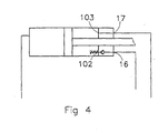
- the cylinder head 10 is provided with two internal ports 102 and 103, the connection ports 16, 17 each being connected to a separate internal port (cf. Fig. 4).
- the hydraulic fluid flows via the second working chamber 12 from the port 16 to the port 17.
- the first working chamber 21 of the second cylinder 2 has two connection ports 26 and 27, which are arranged on cylinder head 20.
- the connection port 27 is in open communication with the internal port 202 in the first working chamber 21 via an internal line 201a (indicated by means of a dashed line) in the cylinder head 20.
- the connection port 26 is connected to the internal port 202 in the first working chamber 21 via a mechanically actuable nonreturn valve 28, which is arranged in the cylinder head 20, and internal lines 201a and 201b.
- the mechanically actuable nonreturn valve 28 can be opened as a result of the piston 23, in the vicinity of the end of the piston stroke, pressing against an actuating member 29 of the nonreturn valve 28.
- hydraulic fluid can flow from the port 26 to the port 27 via the internal lines 201b and 201a.
- the second working chamber 22 of the second cylinder 2 has a connection port 25.
- the control system has a first control valve 30 and a second control valve 40.
- the control valves 30 and 40 are electromagnetic 3/2 valves, i.e. two-position control valves with three ports. In principle, it is also possible to use a 4/2 valve, of which in each case one port is not in use.
- the control valve 30 has a first port 31, which in the first and second positions of the valve 30 is respectively connected to a second port 32 and a third port 33.
- Fig. 1 illustrates the first position, in which the port 31 is connected to the second port 32.
- the control valve 40 has a first port 41, which in the first and second positions of the valve 40 is respectively connected to a second port 42 and a third port 43.
- Fig. 1 shows the first position, in which the port 41 is connected to the second port 42.
- the two ports 32 and 42 of the valves 30, 40 are connected to one another via a short-circuit line 50.
- the first and second control valves 30, 40 have a return spring for returning them to the first position of the corresponding valve 30, 40 in an unactuated state of the corresponding valve 30, 40.
- the third port 33 of the first control valve 30 is connected, via lines 51, 52, to the connection port 15 of the first working chamber 11 in the first cylinder 1 and, via lines 51, 53, to the connection port 26 of the first working chamber 21 of the second cylinder 2.
- the first port 31 of the first control valve 30 is connected, via a line 55, to the connection port 27 of the first working chamber 21 of the second cylinder 2 and, via a line 54, to a first port 71 of a switching valve 70, which is to be described in more detail below.
- the third port 43 of the second control valve 40 is connected, via lines 56, 57, to the connection port 25 of the second working chamber 22 in the second cylinder 2 and, via lines 56, 58, to the connection port 16 of the second working chamber 12 of the first cylinder 1.
- the first port 41 of the second control valve 40 is connected, via a line 59, to the connection port 17 of the second working chamber 12 of the first cylinder 1 and, via a line 60, to a second port 72 of the switching valve 70.
- the switching valve 70 has two positions and four ports 71-74. As has already been stated above, the lines 54 and 60 are respectively connected to the first port 71 and the second port 72. Furthermore, the switching valve 70 has a pump port 73 and a reservoir port 74. The pump port 73 is connected to the pump P via a pump line 61. The reservoir port 74 is connected to the reservoir T via a reservoir line 62.
- the switching valve 70 In a first position of the switching valve 70, which is illustrated in Fig. 1, the pump port 73 is connected to the first port 71 and the reservoir port 74 is connected to the second port 72, so that the line 54 serves as a feed line in the system and the line 60 serves as a return line. In a second position of the switching valve 70, the pump port 73 is connected to the second port 72 and the reservoir port 74 is connected to the first port 71, so that the line 60 serves as a feed line for the remainder of the system and the line 54 serves as a return line. Therefore, the switching valve 70, as a result of the two positions being adopted, can be used to switch the direction of flow of the hydraulic fluid in the control system.
- the switching valve 70 is of what is known as the pressure-controlled type, switching the instant at which the flow of hydraulic fluid in the control system becomes zero, i.e. drops below a defined minimum value.
- a safety valve 80 which ensures that the system pressure in the control system cannot exceed a defined value, is arranged between the pump line 61 and the reservoir line 62.
- Fig. 1 shows the at-rest state, in which the control valves 30 and 40 are not energized, with the result that the two ports 32 and 42 are connected to one another and the hydraulic oil is pumped via the short-circuit line 50 from the pump side direct to the reservoir side. The control system is therefore unpressurized.
- the cycle described here is the loading cycle of the conveyor floor according to the invention.
- the first floor parts 301 are moved under the load by means of the first cylinder 1.
- the second floor parts 302 are moved under the load by means of the second cylinder 2.
- the first and second floor parts 301, 302, together with the load are simultaneously moved back, so that the load is moved, for example, into a loading space of a lorry or the like.
- the first and second floor parts 301, 302 together with the load are displaced simultaneously in such a way that the load is moved, for example, out of a loading space of a lorry or the like.
- the second cylinder 2 is used to pull the second floor parts 302 out from beneath the load.
- the first cylinder 1 is used to pull the first floor parts 301 out from beneath the load. This takes place in the following way:
- the second working chambers 12 and 22 of the first and second cylinders 1, 2 are both in open communication with the reservoir T. Therefore, in both cylinders 1 and 2 there is a pressure difference across the pistons 13 and 23, with the result that they will simultaneously move to the right, as seen in the figure. When they have reached the end of their stroke, the flow of fluid becomes zero and the switching valve 70 is automatically switched over. Now, in the first instance, only the hydraulic fluid out of the first working chamber 21 can flow from the second cylinder 2 to the reservoir T via the lines 55, 54, 62. Therefore, only the piston 23 of the second cylinder 2 will move to the left, as seen in the figure.
- the piston 23 of the second cylinder 2 will open the nonreturn valve 28 via the actuator member 29, with the result that the hydraulic fluid will flow out of the first working chamber 11 of the first cylinder 1, via the lines 52, 53, 201, 55 etc., to the reservoir T with the result that the piston 13 of the first cylinder 1 will move to the left, as seen in the figure.
- the flow in the system once again becomes zero and the switching valve 70 is once again switched over automatically.
- the second control valve 40 is also switched over, with the result that the system returns once again to the at-rest state.
- Fig. 6 shows the control system of an embodiment of a conveyor floor with three slideable floor parts, which are connected to three actuators.
- the embodiment shown in Fig. 6 largely operates in the same way as that shown in Fig. 1. Therefore, identical components are denoted by identical reference numerals.
- one intervening cylinder 103 is arranged between the first and second cylinders 1 and 2, respectively.
- the third port 33 of the first control valve 30 is connected to the first working chamber 11 of the first cylinder 1 and to a first working chamber 131 of the intervening cylinder 103.
- the third port 43 of the second control valve 40 is connected to the second working chamber 22 of the first cylinder 2 and to a second working chamber 132 of the intervening cylinder 103.
- the second working chamber 12 of the first cylinder 1 is connected to the second working chamber 132 of the following intervening cylinder 103 via a line 63.
- the first working chamber 21 of the second cylinder 2 is connected to the first working chamber 131 of the preceding intervening cylinder 103 via a line 64.
- An actuable nonreturn valve 138 which can be actuated by the piston 133 of the intervening cylinder 103 in that position of the piston 133 in which the volume of the second working chamber 132 of the intervening cylinder 103 is at a minimum, is arranged between the second working chamber 132 of the intervening cylinder 103 and the third port 43 of the second control valve 40.
- An actuable nonreturn valve 139 which can be actuated by the piston 133 of the intervening cylinder 103 in that position of the piston 133 in which the volume of the first working chamber 131 of the intervening cylinder 103 is at a minimum, is arranged between the first working chamber 131 of the intervening cylinder 103 and the third port 33 of the first control valve 30.
- an embodiment with more than one intervening actuator is constructed analogously, with the first working chambers of all the intervening actuators being connected to the third port 33 of the first control valve 30 and with the second working chambers of all the intervening actuators being connected to the third port 43 of the second control valve 40. Furthermore, the second working chamber 12 of the first actuator 1 is connected to the second working chamber of one of the intervening actuators, and the first working chamber 21 of the second actuator 2 is connected to the first working chamber of one of the intervening actuators.
- control valves 30 and 40 are electromagnetic control valves. However, it is also possible for the valves to be designed as manually actuated, pneumatically actuated or pressure-controlled control valves.
Landscapes
- Engineering & Computer Science (AREA)
- Mechanical Engineering (AREA)
- Fluid-Pressure Circuits (AREA)
- Measuring Fluid Pressure (AREA)
- Arrangements For Transmission Of Measured Signals (AREA)
Claims (6)
- Flurförderer mit wenigstens ersten und zweiten Flurteilen (301, 302), welche nebeneinander angeordnet sind und in der Längsrichtung hin- und hergleiten können, und mit einem hydraulischen Steuersystem zur Steuerung der verschiebbaren Flurteile (301, 302), wobei das hydraulische Steuersystem aufweist:- eine Pumpe (P),- einen Behälter (T),- einen ersten und einen zweiten hydraulischen Aktuator (1, 2), welche jeweils an die ersten und zweiten Flurteile gekoppelt sind (301 bzw. 302), um die Flurteile (301, 302) hin- und herzuschieben, wobei die ersten und zweiten Aktuatoren (1, 2) vom zweifach wirkenden Typ sind und wobei jeder eine erste und eine zweite variable Arbeitskammer (11, 21; 21, 22) hat, welche durch einen Kolben (13, 23) des entsprechenden Aktuators (1, 2) begrenzt sind,- ein erstes Steuerventil (30) und ein zweites Steuerventil (40) wobei das erste Steuerventil (30) einen ersten Eingang (31), einen zweiten Eingang (32) und einen dritten Eingang (33) hat, wobei in einer ersten Position des ersten Steuerventils (30) der erste Eingang (31) mit dem zweiten Eingang (32) verbunden ist, und wobei in einer zweiten Position der erste Eingang (31) mit dem dritten Eingang (33) verbunden ist, und wobei das zweite Steuerventil (40) einen ersten Eingang (41), einen zweiten Eingang (42) und einen dritten Eingang (43) hat, wobei in einer ersten Position des zweiten Steuerventils (40) der erste Eingang (41) mit dem zweiten Eingang (42) verbunden ist und wobei in einer zweiten Position der erste Eingang (41) mit dem dritten Eingang (43) verbunden ist,- ein Umschaltventil (70) mit einem ersten Eingang (71), einem zweiten Eingang (72), einem Pumpeneingang (73) und einem Behältereingang (74), wobei der Pumpeneingang (73) mit der Pumpe (P) verbunden ist und wobei der Behältereingang (74) mit dem Behälter (T) verbunden ist, wobei in einer ersten Position des Umschaltventils (70) der Pumpeneingang (73) mit dem ersten Eingang (71) verbunden ist und der Behältereingang (74) verbunden ist mit dem zweiten Eingang (72), und wobei in einer zweiten Position der Pumpeneingang (73) mit dem zweiten Eingang (72) verbunden ist und der Behältereingang (74) mit dem ersten Eingang (71) verbunden ist,wobei das Umschaltventil (70), das erste und das zweite Steuerventil (30, 40) und der hydraulische Aktuator (1, 2) wie folgt verbunden sind:der erste Eingang (71) des Umschaltventils (70) ist mit dem ersten Eingang (31) des ersten Steuerventils (30) und mit der ersten Arbeitskammer (21) des zweiten Aktuators (2) verbunden,der zweite Eingang (72) des Umschaltventils (70) ist mit dem ersten Eingang (41) des zweiten Steuerventils (40) und mit der zweiten Arbeitskammer (12) des ersten Aktuators (1) verbunden,der zweite Eingang (32) des ersten Steuerventils (30) ist mit dem zweiten Eingang (42) des zweiten Steuerventils (40) verbunden,der dritte Eingang (33) des ersten Steuerventils (30) ist mit der ersten Arbeitskammer (11) des ersten Aktuators (1) und mit der ersten Arbeitskammer (21) des zweiten Aktuators (2) verbunden,der dritte Eingang (43) des zweiten Steuerventils (40) ist mit der zweiten Arbeitskammer (12) des ersten Aktuators (1) und mit der zweiten Arbeitskammer (22) des zweiten Aktuators (2) verbunden,mit einem betätigbaren Rückschlagventil (18), das durch den Kolben (13) des ersten Aktuators (1) in der Position des Kolbens (13) betätigt werden kann, in welcher das Volumen der zweiten Arbeitskammer (12) des ersten Aktuators (1) bei einem Minimum liegt, wobei dieses zwischen der zweiten Arbeitskammer (12) des ersten Aktuators (1) und dem dritten Eingang (43) des zweiten Steuerventils (40) angeordnet ist, und mit einem betätigbaren Rückschlagventil (28), das durch den Kolben (23) des zweiten Aktuators (2) in der Position des Kolbens (23), in welcher das Volumen der ersten Arbeitskammer (21) des zweiten Aktuators (2) bei einem Minimum liegt, betätigt werden kann, wobei es zwischen der ersten Arbeitskammer (21) des zweiten Aktuators (2) und dem dritten Eingang (33) des ersten Steuerventils (30) angeordnet ist,
dadurch gekennzeichnet, dass das Umschaltventil (70) ein druckgesteuertes Umschaltventil ist, das von der ersten Position auf die zweiten Position oder von der zweiten Position auf die erste Position umschaltet, wenn der Fluss der hydraulischen Flüssigkeit in dem Steuersystem Null ist. - Flurförderer mit wenigstens drei Flurteilen, die nebeneinander angeordnet sind und die in Längsrichtung hin- und hergleiten können, und einem hydraulischen Steuersystem zur Steuerung der verschiebbaren Flurteile, wobei das hydraulische Steuersystem aufweist:- eine Pumpe (P),- einen Behälter (T),- einen ersten hydraulischen Aktuator (1), einen zweiten hydraulischen Aktuator (2) und einen oder mehrere zwischengeschaltete hydraulische Aktuatoren (103), die an die Flurteile gekoppelt sind, um die Flurteile hin- und herzuschieben, wobei die Aktuatoren (1, 2, 103) vom zweifach wirkenden Typ sind, und wobei jeder davon eine erste und eine zweite variable Arbeitskammer (11, 21, 131; 21, 22, 132) aufweist, die durch einen Kolben (13, 23, 133) des entsprechenden Aktuators (1, 2, 103) begrenzt sind,- ein erstes Steuerventil (30) und ein zweites Steuerventil (40), wobei das erste Steuerventil (30) einen ersten Eingang (31), einen zweiten Eingang (32) und einen dritten Eingang (33) hat, wobei in einer ersten Position des ersten Steuerventils (30) der erste Eingang (31) mit dem zweiten Eingang (32) verbunden ist, und wobei in einer zweiten Position der erste Eingang (31) mit dem dritten Eingang (33) verbunden ist, und wobei das zweite Steuerventil (40) einen ersten Eingang (41), einen zweiten Eingang (42) und einen dritten Eingang (43) hat, wobei in einer ersten Position des zweiten Steuerventils (40) der erste Eingang (41) mit dem zweiten Eingang (42) verbunden ist, und wobei in einer zweiten Position der erste Eingang (41) mit dem dritten Eingang (43) verbunden ist,- ein Umschaltventil (70) mit einem ersten Eingang (71), einem zweiten Eingang (72), einem Pumpeneingang (73) und einem Behältereingang (74), wobei der Pumpeneingang (73) mit der Pumpe (P) verbunden ist und wobei der Behältereingang (74) mit dem Behälter (T) verbunden ist, wobei in einer ersten Position des Umschaltventils (70) der Pumpeneingang (73) mit dem ersten Eingang (71) verbunden ist und wobei der Behältereingang (74) mit dem zweiten Eingang (72) verbunden ist, und wobei in einer zweiten Position der Pumpeneingang (73) mit dem zweiten Eingang (72) verbunden ist und der Behältereingang (74) mit dem ersten Eingang (71) verbunden ist,wobei das Umschaltventil (70), das erste und das zweite Steuerventil (30, 40) und die hydraulischen Aktuatoren (1, 2, 103) wie folgt verbunden sind:der erste Eingang (71) des Umschaltventils (70) ist mit dem ersten Eingang (31) des ersten Steuerventils (30) und mit der ersten Arbeitskammer (21) des zweiten Aktuators (2) verbunden,der zweite Eingang (72) des Umschaltventils (70) ist mit dem ersten Eingang (41) des zweiten Steuerventils (40) und mit der zweiten Arbeitskammer (12) des ersten Aktuators (1) verbunden,der zweite Eingang (32) des ersten Steuerventils (30) ist mit dem zweiten Eingang (42) des zweiten Steuerventils (40) verbunden,der dritte Eingang (33) des ersten Steuerventils (30) ist mit der ersten Arbeitskammer (11) des ersten Aktuators (1) und mit der ersten Arbeitskammer (131) der einen oder mehreren zwischengeschalteten Aktuatoren (103) verbunden,der dritte Eingang (43) des zweiten Steuerventils (40) ist mit der zweiten Arbeitskammer (22) des zweiten Aktuators (2) und mit der zweiten Arbeitskammer (132) des einen oder der mehreren zwischengeschalteten Aktuatoren (103) verbunden,die zweite Arbeitskammer (12) des ersten Aktuators (1) ist mit der zweiten Arbeitskammer (132) eines des einen oder der mehreren zwischengeschalteten Aktuatoren (103) verbunden,die erste Arbeitskammer (21) des zweiten Aktuators (2) ist mit der ersten Arbeitskammer (131) eines des einen oder der mehreren zwischengeschalteten Aktuatoren (103) verbunden,mit einem betätigbaren Rückschlagventil (18), welches durch den Kolben (13) des ersten Aktuators (1) in der Position des Kolbens (13), in welcher das Volumen der zweiten Arbeitskammer (12) des ersten Aktuators (1) bei einem Minimum liegt, betätigt werden kann, wobei es zwischen der zweiten Arbeitskammer (12) des ersten Aktuators (1) und der zweiten Arbeitskammer (132) des entsprechenden zwischengeschalteten Aktuators (103) angeordnet ist,
in jedem Fall mit einem betätigbaren Rückschlagventil (138), welches durch den Kolben (133) des zwischengeschalteten Aktuators (103) in der Position des Kolbens (133), in welcher das Volumen der zweiten Arbeitskammer (132) des zwischengeschalteten Aktuators (103) bei einem Minimum liegt, betätigt werden kann, wobei es zwischen der zweiten Arbeitskammer (132) des einen oder der mehreren zwischengeschalteten Aktuatoren (103) und dem dritten Eingang (43) des zweiten Steuerventils (40) angeordnet ist,
mit einem betätigbaren Rückschlagventil (28), das durch den Kolben (23) des zweiten Aktuators (2) in der Position des Kolbens (23), in welcher das Volumen der ersten Arbeitskammer (21) des zweiten Aktuators (2) bei einem Minimum liegt, betätigt werden kann, wobei es zwischen der ersten Arbeitskammer (21) des zweiten Aktuators (2) und der ersten Arbeitskammer (131) des entsprechenden zwischengeschalteten Aktuars (103) angeordnet ist,
in jedem Fall mit einem betätigbaren Rückschlagventil (139), welches durch den Kolben (133) des zwischengeschalteten Aktuators (103) in der Position des Kolbens (133), in welcher das Volumen der ersten Arbeitskammer (133) des zwischengeschalteten Aktuators (103) bei einem Minimum liegt, betätigt werden kann, wobei es zwischen der ersten Arbeitskammer (131) des einen oder der mehreren zwischengeschalteten Aktuatoren (103) und dem dritten Eingang (33) des ersten Steuerventils (30) angeordnet ist,
dadurch gekennzeichnet, dass das Umschaltventil (70) ein druckgesteuertes Umschaltventil ist, welches von der ersten Position auf die zweite Position oder von der zweiten Position auf die erste Position umschaltet, wenn der Fluss der hydraulischen Flüssigkeit in dem Steuersystem Null ist. - Flurförderer gemäß Anspruch 1 oder 2, bei dem das erste und das zweite Steuerventil (30, 40) elektromagnetisch betätigbare Ventile sind.
- Flurförderer gemäß Anspruch 3, bei dem das erste und das zweite Steuerventil eine Rückholfeder haben, um das entsprechende Ventil (30, 40) in seine erste Position im unbetätigten Zustand des entsprechenden Ventils (30, 40) zurückzuholen.
- Flurförderer gemäß Anspruch 1 oder 2, bei dem das erste und das zweite Steuerventil (30, 40) pneumatisch betätigbare Ventile sind.
- Flurförderer gemäß Anspruch 1 oder 2, bei dem das erste und das zweite Steuerventil (30, 40) druckgesteuerte Ventile sind.
Applications Claiming Priority (2)
| Application Number | Priority Date | Filing Date | Title |
|---|---|---|---|
| NL1023582A NL1023582C2 (nl) | 2003-06-02 | 2003-06-02 | Laad- en losvloer. |
| PCT/NL2004/000324 WO2004106197A1 (en) | 2003-06-02 | 2004-05-13 | Conveyor floor |
Publications (2)
| Publication Number | Publication Date |
|---|---|
| EP1628895A1 EP1628895A1 (de) | 2006-03-01 |
| EP1628895B1 true EP1628895B1 (de) | 2007-08-29 |
Family
ID=33487997
Family Applications (1)
| Application Number | Title | Priority Date | Filing Date |
|---|---|---|---|
| EP04732857A Expired - Lifetime EP1628895B1 (de) | 2003-06-02 | 2004-05-13 | Hin- und hergehender flurförderer |
Country Status (5)
| Country | Link |
|---|---|
| EP (1) | EP1628895B1 (de) |
| AT (1) | ATE371614T1 (de) |
| DE (1) | DE602004008619T2 (de) |
| NL (1) | NL1023582C2 (de) |
| WO (1) | WO2004106197A1 (de) |
Family Cites Families (6)
| Publication number | Priority date | Publication date | Assignee | Title |
|---|---|---|---|---|
| US4962848A (en) * | 1990-01-16 | 1990-10-16 | Foster Raymond K | Reciprocating floor conveyor |
| NL9200103A (nl) * | 1992-01-20 | 1993-08-16 | Bert Ronald De Roo | Transporterende laadvloer. |
| US5228555A (en) * | 1992-04-15 | 1993-07-20 | Hallstrom Olof A | Load positioning and conveying system |
| US5622095A (en) * | 1995-06-28 | 1997-04-22 | Foster; Raymond K. | Hydraulic drive and control system |
| US5996773A (en) * | 1998-02-06 | 1999-12-07 | Gist; Richard T. | Fluid drive for reciprocating floor |
| US6513648B1 (en) * | 2000-11-06 | 2003-02-04 | Olof A. Hallstrom | Reciprocating conveyor with top front drive |
-
2003
- 2003-06-02 NL NL1023582A patent/NL1023582C2/nl not_active IP Right Cessation
-
2004
- 2004-05-13 WO PCT/NL2004/000324 patent/WO2004106197A1/en not_active Ceased
- 2004-05-13 DE DE602004008619T patent/DE602004008619T2/de not_active Expired - Lifetime
- 2004-05-13 EP EP04732857A patent/EP1628895B1/de not_active Expired - Lifetime
- 2004-05-13 AT AT04732857T patent/ATE371614T1/de not_active IP Right Cessation
Also Published As
| Publication number | Publication date |
|---|---|
| DE602004008619T2 (de) | 2008-06-05 |
| NL1023582C2 (nl) | 2004-12-03 |
| EP1628895A1 (de) | 2006-03-01 |
| DE602004008619D1 (de) | 2007-10-11 |
| WO2004106197A1 (en) | 2004-12-09 |
| ATE371614T1 (de) | 2007-09-15 |
Similar Documents
| Publication | Publication Date | Title |
|---|---|---|
| EP0633983B1 (de) | Hydraulische vorrichtung mit gleichlaufzylindern | |
| US6171075B1 (en) | Process and device for controlling a two-cylinder thick medium pump | |
| US3969985A (en) | Fluid actuating device for an electric circuit breaker | |
| CN112178006A (zh) | 一种自动换向的液压缸 | |
| CN102640247A (zh) | 阀控装置 | |
| JP3193729B2 (ja) | 位置制御される比例方向弁 | |
| JPS6221994B2 (de) | ||
| US20240200580A1 (en) | Hydraulic system and method for operating a hydraulic system | |
| US7370569B2 (en) | Hydraulic drive | |
| CN109563850B (zh) | 液压驱动设施 | |
| EP1628895B1 (de) | Hin- und hergehender flurförderer | |
| US12509042B2 (en) | Hydraulic system for a brake release device, brake release device with such a hydraulic system and brake system | |
| CN102959252B (zh) | 多流体泵并合回路 | |
| JP3143772B2 (ja) | コンクリートポンプの制御装置 | |
| CN119594083B (zh) | 液压系统及其行程限制和保护装置 | |
| EP0428406A1 (de) | Motor mit abwechselnder Bewegungsrichtung | |
| CN101033700B (zh) | 对两个机组与一个压力介质源的连接进行控制的设备 | |
| US4581510A (en) | Drive for a high-tension circuit breaker | |
| RU2337856C1 (ru) | Комбинированный привод | |
| SU1753026A1 (ru) | Пневмонасос | |
| KR102945505B1 (ko) | 제어 밸브, 유압 회로, 유압 기기 및 건설 기계 | |
| EP0773346A1 (de) | Mit zusammengepresstem Gas arbeitende Maschine | |
| JPH11148503A (ja) | 流体圧シリンダ | |
| JPH06300014A (ja) | アクチュエータ制御装置 | |
| KR960038144A (ko) | 가역 유압 구동장치, 가역 유압 구동장치용 절환 밸브 및 가역유압 구동장치를 왕복운동시키는 방법 |
Legal Events
| Date | Code | Title | Description |
|---|---|---|---|
| PUAI | Public reference made under article 153(3) epc to a published international application that has entered the european phase |
Free format text: ORIGINAL CODE: 0009012 |
|
| 17P | Request for examination filed |
Effective date: 20051111 |
|
| AK | Designated contracting states |
Kind code of ref document: A1 Designated state(s): AT BE BG CH CY CZ DE DK EE ES FI FR GB GR HU IE IT LI LU MC NL PL PT RO SE SI SK TR |
|
| DAX | Request for extension of the european patent (deleted) | ||
| GRAP | Despatch of communication of intention to grant a patent |
Free format text: ORIGINAL CODE: EPIDOSNIGR1 |
|
| GRAS | Grant fee paid |
Free format text: ORIGINAL CODE: EPIDOSNIGR3 |
|
| GRAA | (expected) grant |
Free format text: ORIGINAL CODE: 0009210 |
|
| AK | Designated contracting states |
Kind code of ref document: B1 Designated state(s): AT BE BG CH CY CZ DE DK EE ES FI FR GB GR HU IE IT LI LU MC NL PL PT RO SE SI SK TR |
|
| REG | Reference to a national code |
Ref country code: GB Ref legal event code: FG4D |
|
| REG | Reference to a national code |
Ref country code: CH Ref legal event code: EP |
|
| REG | Reference to a national code |
Ref country code: IE Ref legal event code: FG4D |
|
| REF | Corresponds to: |
Ref document number: 602004008619 Country of ref document: DE Date of ref document: 20071011 Kind code of ref document: P |
|
| PG25 | Lapsed in a contracting state [announced via postgrant information from national office to epo] |
Ref country code: FI Free format text: LAPSE BECAUSE OF FAILURE TO SUBMIT A TRANSLATION OF THE DESCRIPTION OR TO PAY THE FEE WITHIN THE PRESCRIBED TIME-LIMIT Effective date: 20070829 Ref country code: ES Free format text: LAPSE BECAUSE OF FAILURE TO SUBMIT A TRANSLATION OF THE DESCRIPTION OR TO PAY THE FEE WITHIN THE PRESCRIBED TIME-LIMIT Effective date: 20071210 |
|
| PG25 | Lapsed in a contracting state [announced via postgrant information from national office to epo] |
Ref country code: PL Free format text: LAPSE BECAUSE OF FAILURE TO SUBMIT A TRANSLATION OF THE DESCRIPTION OR TO PAY THE FEE WITHIN THE PRESCRIBED TIME-LIMIT Effective date: 20070829 Ref country code: AT Free format text: LAPSE BECAUSE OF FAILURE TO SUBMIT A TRANSLATION OF THE DESCRIPTION OR TO PAY THE FEE WITHIN THE PRESCRIBED TIME-LIMIT Effective date: 20070829 Ref country code: CH Free format text: LAPSE BECAUSE OF FAILURE TO SUBMIT A TRANSLATION OF THE DESCRIPTION OR TO PAY THE FEE WITHIN THE PRESCRIBED TIME-LIMIT Effective date: 20070829 Ref country code: LI Free format text: LAPSE BECAUSE OF FAILURE TO SUBMIT A TRANSLATION OF THE DESCRIPTION OR TO PAY THE FEE WITHIN THE PRESCRIBED TIME-LIMIT Effective date: 20070829 |
|
| REG | Reference to a national code |
Ref country code: CH Ref legal event code: PL |
|
| ET | Fr: translation filed | ||
| PG25 | Lapsed in a contracting state [announced via postgrant information from national office to epo] |
Ref country code: GR Free format text: LAPSE BECAUSE OF FAILURE TO SUBMIT A TRANSLATION OF THE DESCRIPTION OR TO PAY THE FEE WITHIN THE PRESCRIBED TIME-LIMIT Effective date: 20071130 Ref country code: DK Free format text: LAPSE BECAUSE OF FAILURE TO SUBMIT A TRANSLATION OF THE DESCRIPTION OR TO PAY THE FEE WITHIN THE PRESCRIBED TIME-LIMIT Effective date: 20070829 |
|
| PG25 | Lapsed in a contracting state [announced via postgrant information from national office to epo] |
Ref country code: PT Free format text: LAPSE BECAUSE OF FAILURE TO SUBMIT A TRANSLATION OF THE DESCRIPTION OR TO PAY THE FEE WITHIN THE PRESCRIBED TIME-LIMIT Effective date: 20080129 Ref country code: SK Free format text: LAPSE BECAUSE OF FAILURE TO SUBMIT A TRANSLATION OF THE DESCRIPTION OR TO PAY THE FEE WITHIN THE PRESCRIBED TIME-LIMIT Effective date: 20070829 Ref country code: CZ Free format text: LAPSE BECAUSE OF FAILURE TO SUBMIT A TRANSLATION OF THE DESCRIPTION OR TO PAY THE FEE WITHIN THE PRESCRIBED TIME-LIMIT Effective date: 20070829 |
|
| PG25 | Lapsed in a contracting state [announced via postgrant information from national office to epo] |
Ref country code: SE Free format text: LAPSE BECAUSE OF FAILURE TO SUBMIT A TRANSLATION OF THE DESCRIPTION OR TO PAY THE FEE WITHIN THE PRESCRIBED TIME-LIMIT Effective date: 20071129 Ref country code: RO Free format text: LAPSE BECAUSE OF FAILURE TO SUBMIT A TRANSLATION OF THE DESCRIPTION OR TO PAY THE FEE WITHIN THE PRESCRIBED TIME-LIMIT Effective date: 20070829 |
|
| PLBE | No opposition filed within time limit |
Free format text: ORIGINAL CODE: 0009261 |
|
| STAA | Information on the status of an ep patent application or granted ep patent |
Free format text: STATUS: NO OPPOSITION FILED WITHIN TIME LIMIT |
|
| 26N | No opposition filed |
Effective date: 20080530 |
|
| PG25 | Lapsed in a contracting state [announced via postgrant information from national office to epo] |
Ref country code: MC Free format text: LAPSE BECAUSE OF NON-PAYMENT OF DUE FEES Effective date: 20080531 |
|
| GBPC | Gb: european patent ceased through non-payment of renewal fee |
Effective date: 20080513 |
|
| PG25 | Lapsed in a contracting state [announced via postgrant information from national office to epo] |
Ref country code: EE Free format text: LAPSE BECAUSE OF FAILURE TO SUBMIT A TRANSLATION OF THE DESCRIPTION OR TO PAY THE FEE WITHIN THE PRESCRIBED TIME-LIMIT Effective date: 20070829 |
|
| PG25 | Lapsed in a contracting state [announced via postgrant information from national office to epo] |
Ref country code: IE Free format text: LAPSE BECAUSE OF NON-PAYMENT OF DUE FEES Effective date: 20080513 |
|
| PG25 | Lapsed in a contracting state [announced via postgrant information from national office to epo] |
Ref country code: SI Free format text: LAPSE BECAUSE OF FAILURE TO SUBMIT A TRANSLATION OF THE DESCRIPTION OR TO PAY THE FEE WITHIN THE PRESCRIBED TIME-LIMIT Effective date: 20070829 Ref country code: GB Free format text: LAPSE BECAUSE OF NON-PAYMENT OF DUE FEES Effective date: 20080513 |
|
| PG25 | Lapsed in a contracting state [announced via postgrant information from national office to epo] |
Ref country code: CY Free format text: LAPSE BECAUSE OF FAILURE TO SUBMIT A TRANSLATION OF THE DESCRIPTION OR TO PAY THE FEE WITHIN THE PRESCRIBED TIME-LIMIT Effective date: 20070829 |
|
| PG25 | Lapsed in a contracting state [announced via postgrant information from national office to epo] |
Ref country code: BG Free format text: LAPSE BECAUSE OF FAILURE TO SUBMIT A TRANSLATION OF THE DESCRIPTION OR TO PAY THE FEE WITHIN THE PRESCRIBED TIME-LIMIT Effective date: 20071129 |
|
| PG25 | Lapsed in a contracting state [announced via postgrant information from national office to epo] |
Ref country code: LU Free format text: LAPSE BECAUSE OF NON-PAYMENT OF DUE FEES Effective date: 20080513 Ref country code: HU Free format text: LAPSE BECAUSE OF FAILURE TO SUBMIT A TRANSLATION OF THE DESCRIPTION OR TO PAY THE FEE WITHIN THE PRESCRIBED TIME-LIMIT Effective date: 20080301 |
|
| PG25 | Lapsed in a contracting state [announced via postgrant information from national office to epo] |
Ref country code: TR Free format text: LAPSE BECAUSE OF FAILURE TO SUBMIT A TRANSLATION OF THE DESCRIPTION OR TO PAY THE FEE WITHIN THE PRESCRIBED TIME-LIMIT Effective date: 20070829 |
|
| PG25 | Lapsed in a contracting state [announced via postgrant information from national office to epo] |
Ref country code: IT Free format text: LAPSE BECAUSE OF NON-PAYMENT OF DUE FEES Effective date: 20080531 |
|
| PGFP | Annual fee paid to national office [announced via postgrant information from national office to epo] |
Ref country code: FR Payment date: 20110610 Year of fee payment: 8 |
|
| PGFP | Annual fee paid to national office [announced via postgrant information from national office to epo] |
Ref country code: BE Payment date: 20110530 Year of fee payment: 8 Ref country code: NL Payment date: 20110608 Year of fee payment: 8 |
|
| PGFP | Annual fee paid to national office [announced via postgrant information from national office to epo] |
Ref country code: DE Payment date: 20110525 Year of fee payment: 8 |
|
| BERE | Be: lapsed |
Owner name: DE ROO, BERT RONALD Effective date: 20120531 |
|
| REG | Reference to a national code |
Ref country code: NL Ref legal event code: V1 Effective date: 20121201 |
|
| PG25 | Lapsed in a contracting state [announced via postgrant information from national office to epo] |
Ref country code: BE Free format text: LAPSE BECAUSE OF NON-PAYMENT OF DUE FEES Effective date: 20120531 |
|
| REG | Reference to a national code |
Ref country code: FR Ref legal event code: ST Effective date: 20130131 |
|
| REG | Reference to a national code |
Ref country code: DE Ref legal event code: R119 Ref document number: 602004008619 Country of ref document: DE Effective date: 20121201 |
|
| PG25 | Lapsed in a contracting state [announced via postgrant information from national office to epo] |
Ref country code: NL Free format text: LAPSE BECAUSE OF NON-PAYMENT OF DUE FEES Effective date: 20121201 |
|
| PG25 | Lapsed in a contracting state [announced via postgrant information from national office to epo] |
Ref country code: FR Free format text: LAPSE BECAUSE OF NON-PAYMENT OF DUE FEES Effective date: 20120531 |
|
| PG25 | Lapsed in a contracting state [announced via postgrant information from national office to epo] |
Ref country code: DE Free format text: LAPSE BECAUSE OF NON-PAYMENT OF DUE FEES Effective date: 20121201 |