EP1628840B1 - An einem farbbehälter montierbare malerrollerschale - Google Patents
An einem farbbehälter montierbare malerrollerschale Download PDFInfo
- Publication number
- EP1628840B1 EP1628840B1 EP04748581A EP04748581A EP1628840B1 EP 1628840 B1 EP1628840 B1 EP 1628840B1 EP 04748581 A EP04748581 A EP 04748581A EP 04748581 A EP04748581 A EP 04748581A EP 1628840 B1 EP1628840 B1 EP 1628840B1
- Authority
- EP
- European Patent Office
- Prior art keywords
- paint
- roller tray
- paint roller
- arms
- container
- Prior art date
- Legal status (The legal status is an assumption and is not a legal conclusion. Google has not performed a legal analysis and makes no representation as to the accuracy of the status listed.)
- Expired - Lifetime
Links
- 239000003973 paint Substances 0.000 title claims abstract description 181
- 230000008878 coupling Effects 0.000 claims abstract description 16
- 238000010168 coupling process Methods 0.000 claims abstract description 16
- 238000005859 coupling reaction Methods 0.000 claims abstract description 16
- ATJFFYVFTNAWJD-UHFFFAOYSA-N Tin Chemical compound [Sn] ATJFFYVFTNAWJD-UHFFFAOYSA-N 0.000 claims description 17
- 230000000063 preceeding effect Effects 0.000 claims 3
- 238000007688 edging Methods 0.000 claims 1
- 241000870659 Crassula perfoliata var. minor Species 0.000 description 8
- 238000010276 construction Methods 0.000 description 1
- 239000003292 glue Substances 0.000 description 1
- 238000004519 manufacturing process Methods 0.000 description 1
- 239000000463 material Substances 0.000 description 1
- 238000010422 painting Methods 0.000 description 1
- 238000005096 rolling process Methods 0.000 description 1
Images


Classifications
-
- B—PERFORMING OPERATIONS; TRANSPORTING
- B44—DECORATIVE ARTS
- B44D—PAINTING OR ARTISTIC DRAWING, NOT OTHERWISE PROVIDED FOR; PRESERVING PAINTINGS; SURFACE TREATMENT TO OBTAIN SPECIAL ARTISTIC SURFACE EFFECTS OR FINISHES
- B44D3/00—Accessories or implements for use in connection with painting or artistic drawing, not otherwise provided for; Methods or devices for colour determination, selection, or synthesis, e.g. use of colour tables
- B44D3/12—Paint cans; Brush holders; Containers for storing residual paint
- B44D3/126—Paint roller trays
-
- B—PERFORMING OPERATIONS; TRANSPORTING
- B05—SPRAYING OR ATOMISING IN GENERAL; APPLYING FLUENT MATERIALS TO SURFACES, IN GENERAL
- B05C—APPARATUS FOR APPLYING FLUENT MATERIALS TO SURFACES, IN GENERAL
- B05C17/00—Hand tools or apparatus using hand held tools, for applying liquids or other fluent materials to, for spreading applied liquids or other fluent materials on, or for partially removing applied liquids or other fluent materials from, surfaces
- B05C17/02—Rollers ; Hand tools comprising coating rollers or coating endless belts
- B05C17/0245—Accessories
Definitions
- the invention relates to a paint roller tray for placing on a paint container, in particular a paint tin or paint bucket, which paint roller tray is provided with a bottom having a raised edge running along at least a part of its periphery, the edge ending at a point, above an opening situated in the top of the paint container when the paint roller tray is placed on a paint container, whereby the paint roller tray, furthermore, comprises a means of for coupling, for coupling the paint roller tray to a paint container, in a detachable way, especially to the rim of an opening in the paint container, and two flexible arms, whereby the means for coupling is are situated at or near the free ends of the arms.
- Paint roller trays are used for painting with paint rollers.
- the paint roller can be dipped directly into the paint, in the paint container, and then rolled over the bottom of the paint roller tray in order to spread the paint over the roller and remove any excess paint from it.
- the excess paint flows back through the opening into the paint container. In this way, it is not necessary to put the paint in the paint roller tray first, as is the case with paint roller trays which cannot be placed on a paint container and which are provided with a receptacle for the paint.
- a paint roller tray of the type described in the preamble is known from the American patent US-A 5.472.111 .
- This known paint roller tray is provided with two flexible handles on the underside, which extend downwards, on which there are projections for coupling the paint roller tray to the rim of a paint bucket. Because these handles are short and the projections are small and rigid, this known paint roller tray is only suitable for use in combination with a paint container provided with an opening and a rim for which the handles with projections have been designed.
- An objective of the invention is to provide a paint roller tray of the type described in the preamble which can be fitted on different paint containers.
- the paint roller tray according to the invention is characterized in that the arms extend beyond the periphery of the bottom. Because of this , the paint roller tray can be coupled to paint containers of which the shape of the rim and the size of the opening may vary.
- the arms preferably are attached to the raised edge at the ends of the raised edge.
- the raised edge extends from the bottom to at least two edges opposite each other and the place where the raised edge ends extends from the bottom along an additional edge, whereby the arms are attached to the raised edge and are extensions of the raised edge.
- a further embodiment of the paint roller tray is characterized in that the each means for coupling comprises at least one flexible hook, for hooking onto, in, behind or under a paint container's rim.
- the hooks are situated in the surfaces of the arms.
- the means of coupling preferably comprises at least one additional flexible hook, in which the free outer ends of the hooks are aimed in opposite directions, preferably towards each other.
- Still a further embodiment of the paint roller tray is characterized in that the bottom at the place where the raised edges stops is provided with an edge especially for removing excess paint from a paint brush, which edge is provided with notches.
- a further embodiment of the paint roller tray according to the invention which is less expensive to manufacture than the previously described embodiments is characterized in that the raised edge comprises a back wall and two side walls and that the paint roller tray is made from a flat sheet which can be folded and is provided with a bottom section, which after being folded forms the bottom part, and three wall sections, which form the walls after being folded.
- a further embodiment of the paint roller tray which again is executed as a paint roller tray for placing on a paint container provided with flexible arms and without a part in which paint can be put, is characterized in that the paint roller tray's arms are extensions of the side walls, and that the sheet, moreover, comprises two arm sections, which are an extension of and are attached to the wall sections forming the side walls.
- the arms are provided with holes near the free outer ends, as well as gaps which run from the holes to the edges of the arms, for hooking onto a flange round the opening of a paint container.
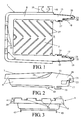
- a first embodiment of the paint roller tray 1 according to the invention is shown in a view from above, a side view and rear view respectively, and in figures 4 and 5 the paint roller tray 1 is shown situated on a first type of paint tin 3 and a second type of paint tin 5.
- the paint roller tray 1 is made from one piece of plastic and has a rectangular bottom 7 with a raised edge 8, which extends along three sides and stops at a fourth side 9. The place where the raised edge stops 9 is situated above an opening 11, 12 in the top of the paint tin 3, 5 when the paint roller tray 1 is situated on a paint tin 3, 5; see figures 4 and 5 .
- the paint roller tray 1 has two flexible arms 13 and 15, one on each side of the place where the raised edge stops 9.
- the arms 13, 15 extend beyond the bottom, as viewed in a direction perpendicular to the bottom 7, and are an extension of the raised edge 8 to which they are attached.
- Each arm is provided with a means of coupling which is made up of two flexible hooks 17, 19 and 18, 20.
- the hooks 17, 19 and 18, 20 are situated in the surface of the arms 13 and 15 and the outer ends of the hooks 17 and 19, 18 and 20 respectively are turned towards each other.
- the hooks 19 and 20 are provided with holes 21 and 22 and gaps 23, 24 which run from the holes to an edge of the arms; see figures 1 and 2 .
- These holes 21 and 22 are especially for hooking onto a flange 6 round the opening 12 of another type of paint tin. This is shown in figure 5 where the paint roller tray 1 is situated on this paint tin 5 and in which the rim round the opening consists of a flange 6 bent outwards.
- the bottom 7 of the paint roller tray 1 is provided with ridges 27 in order to be able roll a paint roller over it better and, the place where the raised edge stops 9, is provided with an edge 29 with notches for removing excess paint from a paint brush.
- the paint roller tray 1 is provided with openings 33 of various sizes in the rearmost part 31 of the raised edge 7, for holding paint rollers or paint brushes.
- each arm 13, 15 there is a flexible lip 35, 37 in which a stirrer can be clamped. Furthermore, there is a holder 39 provided with an opening 41 for hanging a paint brush, situated on the raised edge.
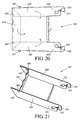
- a second embodiment of the paint roller tray 51 according to the invention is shown in a view from above, a side view and a front view respectively. All parts which are the same or have the same function as those of the first embodiment are indicated by the same reference numbers.
- the arms 53, 55 and the hooks 57, 59 have a different shape.
- the hooks 57, 59 can be hooked here behind a bucket's outer rim.
- This paint roller tray 51 is therefore particularly suitable for use on paint buckets.
- flaps 61, 63 on the arms 53, 55 which when placing the paint roller tray 51 on a paint bucket are situated against the inner rim of the opening at the top of the paint bucket in order to give the paint roller tray more stability.
- a third embodiment of the paint roller tray 71 according to the invention is shown in a view from above, a side view and a front view respectively.
- all parts which are the same or have the same function as those of the first embodiment are indicated by the same reference numbers.
- the hooks 77, 79 are executed here as double hooks 81, 83 and 85, 87, which again can also be hooked onto the outer rim of a bucket.
- the largest hook 81, 85 or the smallest hook 83, 87 or both can be used.
- the hooks 77, 79 are situated transversely on the outer ends of the arms 73, 75.
- a fourth embodiment ofthe paint roller tray 91 according to the invention is shown in a view from above, a side view and a front view respectively.
- all parts which are the same or have the same function as those of the first embodiment are indicated by the same reference numbers.
- the arms 93 and the hooks 95 again have a different shape.
- the hooks 95 again can also be hooked behind the outer rim of a bucket.
- This paint roller tray 91 is provided with a pen 99 on a projecting part 97 of the raised edge 8, on which the handle of a paint roller can be hung.
- auxiliary hook 96 can be hooked behind the hook 95; see figure 14 .
- This auxiliary hook 96 is situated transversely on the end of the arm 93 and is provided with a slot 98 which can be placed over the hook 95.
- a fourth embodiment of the paint roller tray 101 according to the invention is shown in a view from above, a side view and a front view respectively.
- all parts which are the same or have the same function as those of the first embodiment are indicated by the same reference numbers.
- the arms 103 and the hooks 105 again have a somewhat different shape because this paint roller tray 101 is suitable for fitting on small paint tins of one litre.
- the arms 103 of this paint roller tray 101 can be shoved along the rim of a paint tin so that the position of the tray with respect to the opening in the paint tin can be adjusted.
- FIGS 18 and 19 a first embodiment of the paint roller tray according to the invention, which can be folded from a flat sheet, is shown before being folded and after being folded.
- This paint roller tray 111 is made from one flat sheet 113 that can be folded.
- the paint roller tray has a receptacle 115 provided with a rectangular bottom part 117 that is enclosed by two side walls 121 and 123, a back wall 125 and an edge 127 provided with notches for removing any excess paint from a paint brush.
- the sheet 113 has a bottom section 117', which after being folded forms the bottom part 117, three wall sections 121', 123' and 125', which after being folded form the side walls 121 and 123 and the back wall 125, and a section 127' which after being folded forms the edge for removing excess paint 127.
- the wall section 125' which forms the back wall 125 is provided with projecting parts 139, which after being folded extend beyond the side walls, and are provided with openings 141 in which after being folded the side walls hook with their upper edge 143.
- the paint roller tray 111 furthermore, has two arms 167 and 169, which are an extension of the side walls 121 and 123, and the sheet 113 has two arm sections 167' and 169', which are extensions of and are attached to the wall sections 121' and 123' which form the side walls.
- the free outer ends of the arm sections after being folded, are a part of the means of coupling for coupling the paint roller tray to a paint container in such a way that it can also be detached, especially to a rim of an opening in a paint tin or paint bucket.
- This means of coupling is made up of flexible hooks 171 and 173, which are a part of the arms, for hooking onto, in, behind or under a paint container's rim.
- the back wall 125 there is a stepped opening 175 in which a paint brush or paint roller can be placed by its handle.
- the bottom part 117 may be provided with ridges which protrude upwards (not shown).
- a second embodiment of the paint roller tray 181 is shown, which can be folded from a flat sheet, before being folded 183 and after being folded respectively.
- the wall sections 185' which form the side walls 185 are, in this embodiment, provided with projecting tabs 187 which can be folded down in the openings 189 situated in the wall section 191' which forms the back wall 191.
- the arm sections 193' which form the arms 193, moreover, are provided with holes 195 near the free outer ends and gaps 197 run from the holes to the edges of the arms for hooking onto a flange round the paint container's opening.
- a third embodiment of the paint roller tray 201 which can be folded from a flat sheet, is shown before being folded and after being folded respectively, in a view from above and a view from below respectively.
- the paint roller tray 201 is made from one flat sheet 203 which can be folded.
- the sheet 203 is made of plastic, for example, and is provided with folding lines which have been made beforehand and which are formed by making the sheet thinner or by cutting into the sheet.
- the sheet can also be made from other materials, such as cardboard which may or may not be plasticized on one or both sides.
- the paint roller tray 201 has a receptacle 205 provided with two rectangular bottom parts 207, 209. One of the bottom parts 207 is enclosed by two side walls 211, 213 and a back wall 215. The other bottom part 209 is enclosed by two additional side walls 217, 219 and a front wall 221. A bottom wall 223 is situated between the two bottom parts 207 and 209 and the connecting walls 225, 227 are situated between the side wall 211,213 and the additional side walls 217, 219.
- the sheet 203 has two bottom sections 207', 209', which after being folded, form the bottom parts 207, 209, three wall sections 211', 213' and 215', which after being folded form the side walls 211, 213 and the back wall 215, and three additional wall sections 217', 219' and 221', which after being folded form the additional side walls 217, 219 and the front wall 221.
- the wall sections 221' and 215' which form the front and back walls 221 and 215, are provided with projecting parts 229, which after being folded extend beyond the side walls 211, 213 and additional side walls 217, 219, and are provided with openings 231 in which the side walls and additional side walls hook with their upper edges 233 and 235.
- additional folding lines 241, 243 in the front and back walls which are a continuation of the folding lines 237 and 239 between the side walls and the additional side walls on the one side and the two bottom parts on the other side.
- the openings 231 abut these additional folding lines 241 and 243 and extend from these additional folding lines outwards.
- additional folding lines 253 and 255 between the front and back walls and the side walls.
- the sheet has a U-shaped projection 261' which after being folded is a support 261 under the higher-lying bottom part 207.
- This bottom part 207 acts as a surface for rolling off the excess paint on a paint roller and for this purpose is also provided with ridges 263 which protrude upwards.
- the other bottom part 209 forms the bottom of a container in which paint can be put into which a paint roller can be dipped.
- the sheet 203 is also provided with a pre-cut tearing line 265.
- the sheet can easily be torn along this tearing line, as a result of which the wall section 221' with the bottom section 209' and parts 267 of the additional wall sections 217' and 219' can be removed from the rest of the sheet, after which one has a paint roller tray which is comparable to the embodiment described above.
- the paint roller tray according to the invention can be used not only for paint, but glue as well.
- the holes 21, 22 and the gaps 23, 24 of the first embodiment may also be omitted because paint tins with flanges are being used less and less.
Landscapes
- Engineering & Computer Science (AREA)
- Mechanical Engineering (AREA)
- Coating Apparatus (AREA)
- Details Of Rigid Or Semi-Rigid Containers (AREA)
- Mechanical Pencils And Projecting And Retracting Systems Therefor, And Multi-System Writing Instruments (AREA)
- Application Of Or Painting With Fluid Materials (AREA)
Claims (9)
- Farbrollerwanne (1; 51; 71; 91; 101; 111; 181; 201) für die Anbringung an einem Farbbehälter, insbesondere an einer Farbdose oder einem Farbeimer, wobei die Farbrollerwanne mit einem Boden (7) versehen ist, der entlang seinem Umfang zumindest teilweise eine Aufkantung (8) besitzt, die an einer Stelle oberhalb einer Öffnung in der Oberseite des Farbbehälters endet, wenn sich die Farbrollerwanne auf einem Farbbehälter befindet, und wobei die Farbrollerwanne ferner Verbindungsmittel (19, 20) für die trennbare Verbindung der Farbrollerwanne mit dem Farbbehälter sowie zwei biegsame Arme (13, 15) umfasst, wobei die Verbindungsmittel (19, 20) an den freien Enden der Arme oder in deren Nähe angeordnet sind, dadurch gekennzeichnet, dass die Arme über den äußeren Rand des Bodens hinausreichen.
- Farbrollerwanne (1; 51; 71; 91; 101; 111; 181; 201) nach Anspruch 1, dadurch gekennzeichnet, dass die Arme (13, 15) an den Enden der Aufkantung an dieser Aufkantung befestigt sind.
- Farbrollerwanne (1; 51; 71; 91; 101; 111; 181; 201) nach Anspruch 2, dadurch gekennzeichnet, dass die Aufkantung über mindestens zwei einander gegenüberliegende Ränder des Bodens verläuft und sich die Stellen, an denen die Aufkantung endet, im Bereich eines weiteren Randes des Bodens befinden, wobei die Arme an der Aufkantung befestigt sind und Verlängerungen der Aufkantung bilden.
- Farbrollerwanne (1; 51; 71; 91; 101; 111; 181; 201) nach einem der vorangegangenen Ansprüche, dadurch gekennzeichnet, dass jedes der Verbindungsmittel mindestens einen biegsamen Haken umfasst, der dazu vorgesehen ist, an, in, hinter oder unter einem Rand eines Farbbehälters festgehakt zu werden.
- Farbrollerwanne (1; 51; 71; 91; 101; 111; 181; 201) nach Anspruch 4, dadurch gekennzeichnet, dass sich die Haken in der Ebene der Arme befinden.
- Farbrollerwanne (1; 51; 71; 91; 101; 111; 181; 201) nach einem der Ansprüche 4 oder 5, dadurch gekennzeichnet, dass die Verbindungsmittel mindestens einen weiteren biegsamen Haken umfassen, wobei die freien Enden der Haken in entgegengesetzte Richtungen, vorzugsweise jedoch zueinander zeigen.
- Farbrollerwanne (1; 181) nach einem der vorangegangenen Ansprüche, dadurch gekennzeichnet, dass die Arme in der Nähe der freien Enden mit Öffnungen sowie mit von den Öffnungen zu den Rändern der Arme verlaufenden Schlitzen versehen sind, die dazu vorgesehen sind, an einem Falz entlang der Öffnung eines Farbbehälters festgehakt zu werden.
- Farbrollerwanne (111; 181; 201) nach einem der vorangegangenen Ansprüche, dadurch gekennzeichnet, dass die Aufkantung eine Rückwand und zwei Seitenwände umfasst und die Farbrollerwanne durch eine faltbare, flache Platte gebildet wird, die mit einer Bodensektion versehen ist, welche nach dem Falten das Bodenelement bildet, sowie mit an drei Rändern der Bodensektion vorhandenen Wandsektionen, die nach dem Falten die Wände bilden.
- Farbrollerwanne (111; 181; 201) nach Anspruch 8, dadurch gekennzeichnet, dass die Arme der Farbrollerwanne in einer Linie mit den Seitenwänden liegen und die Platte ferner zwei Armsektionen umfasst, die in einer Linie mit den Wandsektionen liegen, die die Seitenwände bilden, und daran befestigt sind.
Applications Claiming Priority (6)
| Application Number | Priority Date | Filing Date | Title |
|---|---|---|---|
| NL1023418 | 2003-05-14 | ||
| NL1023467 | 2003-05-19 | ||
| NL1023673 | 2003-06-16 | ||
| NL1023986A NL1023986C2 (nl) | 2003-05-14 | 2003-07-24 | Verfrollerbak voor plaatsing op een verfhouder. |
| NL1025151 | 2003-12-30 | ||
| PCT/NL2004/000336 WO2004101170A2 (en) | 2003-05-14 | 2004-05-14 | Paint roller tray mountable on a paint container |
Publications (2)
| Publication Number | Publication Date |
|---|---|
| EP1628840A2 EP1628840A2 (de) | 2006-03-01 |
| EP1628840B1 true EP1628840B1 (de) | 2009-04-22 |
Family
ID=33459220
Family Applications (1)
| Application Number | Title | Priority Date | Filing Date |
|---|---|---|---|
| EP04748581A Expired - Lifetime EP1628840B1 (de) | 2003-05-14 | 2004-05-14 | An einem farbbehälter montierbare malerrollerschale |
Country Status (8)
| Country | Link |
|---|---|
| US (1) | US20060064843A1 (de) |
| EP (1) | EP1628840B1 (de) |
| AT (1) | ATE429339T1 (de) |
| CA (1) | CA2566211A1 (de) |
| DE (1) | DE602004020760D1 (de) |
| ES (1) | ES2327414T3 (de) |
| NL (2) | NL1023986C2 (de) |
| WO (1) | WO2004101170A2 (de) |
Families Citing this family (19)
| Publication number | Priority date | Publication date | Assignee | Title |
|---|---|---|---|---|
| GB2433513A (en) * | 2005-12-23 | 2007-06-27 | Ici Plc | A coating system |
| DE102008014706B4 (de) | 2008-03-18 | 2022-05-25 | Nespoli Group Spa | Vorrichtung zur Entfernung überschüssiger Farbe von einem Anstreichwerkzeug |
| MX2009005500A (es) | 2009-05-25 | 2010-11-24 | Alberto Velazquez Arvizu | Accesorio para suministrar liquidos a un aplicador como rodillo y brocha. |
| EP2643166B1 (de) * | 2010-11-24 | 2015-05-06 | Jan Henrik Petersen | Plattensystem für farbverteilung |
| US8991639B2 (en) | 2011-08-09 | 2015-03-31 | Steven R. Kells | Portable work bench paint tray with stair adaptor |
| US8657144B2 (en) | 2011-08-09 | 2014-02-25 | Steven R. Kells | Portable work bench paint tray with stair adaptor |
| CA2778076C (en) * | 2012-02-27 | 2017-10-31 | Katch Kan Holdings Ltd. | Line pipe tray |
| US9662929B2 (en) | 2013-03-06 | 2017-05-30 | Lenoard John Smith | Painting accessory |
| USD723235S1 (en) | 2013-11-20 | 2015-02-24 | Bercom International, Llc | Paint roller grid |
| USD740509S1 (en) | 2014-05-16 | 2015-10-06 | Bercom International, Llc | Paint roller grid with handle |
| GB2536505A (en) * | 2015-03-20 | 2016-09-21 | John Charles Milford Robert | Paint can rim protector assembly |
| GB2558526A (en) * | 2016-08-10 | 2018-07-18 | Qbis Uk Ltd | Paint tray with removable liner |
| USD977774S1 (en) | 2019-03-29 | 2023-02-07 | Bercom International, Llc | Paint grid |
| US12491730B2 (en) * | 2019-08-08 | 2025-12-09 | Tovarna Llc | Paint tray |
| US11667147B2 (en) | 2019-08-08 | 2023-06-06 | Tovarna Llc | Paint tray |
| KR102100972B1 (ko) * | 2019-09-25 | 2020-04-14 | 전미영 | 페인트 캡 트레이 |
| US12296616B2 (en) * | 2021-02-12 | 2025-05-13 | Michael Alvarez | Painting systems and paint devices and related methods |
| GB2610664B (en) * | 2022-02-10 | 2024-01-31 | Paul Winpenny Christopher | Roller tray |
| USD1032987S1 (en) | 2022-05-31 | 2024-06-25 | Christian Sassani | Paint tray |
Family Cites Families (10)
| Publication number | Priority date | Publication date | Assignee | Title |
|---|---|---|---|---|
| US2988260A (en) * | 1959-11-02 | 1961-06-13 | Waldorf Paper Products Co | Paint trays |
| US3168962A (en) * | 1963-07-24 | 1965-02-09 | Rawlins Julia | Brush wiper and holder |
| US4275818A (en) * | 1979-04-11 | 1981-06-30 | The Paint Brush Holder Company | Paint brush holder and wiper |
| US4561556A (en) * | 1984-02-01 | 1985-12-31 | Bendix Roger J | Holder for paint brushes, rollers or the like |
| US5085386A (en) * | 1990-03-27 | 1992-02-04 | Thomas W. Hicks | Paintbrush holder |
| CA2035553A1 (en) * | 1991-02-01 | 1992-08-02 | Raymond Elliott | Folding paint tray |
| US5283928A (en) * | 1992-11-04 | 1994-02-08 | Padco, Inc. | Universal paint grid |
| SE9301288L (sv) * | 1993-04-20 | 1994-04-25 | Sven Eric Paars | Avstrykarskiva för arbetsredskap, t ex roller |
| GB2281894B (en) * | 1993-09-16 | 1997-10-08 | Ici Plc | Combination of a paint container, lid and a paint-roller tray |
| US7036182B2 (en) * | 2002-09-16 | 2006-05-02 | The Wooster Brush Company | Paint roller grid and grid assembly |
-
2003
- 2003-07-24 NL NL1023986A patent/NL1023986C2/nl not_active IP Right Cessation
-
2004
- 2004-05-14 EP EP04748581A patent/EP1628840B1/de not_active Expired - Lifetime
- 2004-05-14 ES ES04748581T patent/ES2327414T3/es not_active Expired - Lifetime
- 2004-05-14 AT AT04748581T patent/ATE429339T1/de not_active IP Right Cessation
- 2004-05-14 DE DE602004020760T patent/DE602004020760D1/de not_active Expired - Lifetime
- 2004-05-14 CA CA002566211A patent/CA2566211A1/en not_active Abandoned
- 2004-05-14 WO PCT/NL2004/000336 patent/WO2004101170A2/en not_active Ceased
- 2004-11-17 NL NL1027530A patent/NL1027530C1/nl not_active IP Right Cessation
-
2005
- 2005-11-14 US US11/272,630 patent/US20060064843A1/en not_active Abandoned
Also Published As
| Publication number | Publication date |
|---|---|
| EP1628840A2 (de) | 2006-03-01 |
| ATE429339T1 (de) | 2009-05-15 |
| ES2327414T3 (es) | 2009-10-29 |
| NL1027530C1 (nl) | 2005-07-04 |
| US20060064843A1 (en) | 2006-03-30 |
| WO2004101170A3 (en) | 2005-04-28 |
| NL1023986C2 (nl) | 2004-11-18 |
| DE602004020760D1 (de) | 2009-06-04 |
| CA2566211A1 (en) | 2004-11-25 |
| WO2004101170A2 (en) | 2004-11-25 |
| WO2004101170A8 (en) | 2007-08-16 |
Similar Documents
| Publication | Publication Date | Title |
|---|---|---|
| EP1628840B1 (de) | An einem farbbehälter montierbare malerrollerschale | |
| US5472111A (en) | Paint roller tray | |
| US8016075B2 (en) | Paint tray | |
| US6102235A (en) | Lid with integral paint roller tray | |
| US8042690B2 (en) | Wiper blade package | |
| US7137168B2 (en) | Paint roller grid | |
| US4928843A (en) | Integrated paint can and roller pan | |
| US20100089931A1 (en) | Paint container accessory | |
| US4247013A (en) | Drip bar for brushes | |
| US5228159A (en) | Combination tool for painters or the like | |
| US6513771B1 (en) | Handy paint holder | |
| US6907640B2 (en) | Vertical paint tray | |
| WO2000078623A1 (en) | Handle with attachment assembly and method | |
| US8434192B2 (en) | Shield for paint roller | |
| US11279169B2 (en) | Paint tray for use with rollers and brushes | |
| WO2005077782A1 (en) | A paintbrush holder | |
| US5277467A (en) | Stackable, foldable, snap-on carton holder | |
| US20090285997A1 (en) | Paintbrush and edger holder | |
| EP4438510B1 (de) | Schachtel zum verpacken von kuchen und feingebäck | |
| JP3219369U (ja) | 塗装用具 | |
| WO2005042363A1 (en) | Versatile and foldable box | |
| JPS6137636Y2 (de) | ||
| WO2000037320A2 (en) | Novel lid for container | |
| JPH086527Y2 (ja) | スプレー塗装用塗料飛散防止箱 | |
| JP3002148U (ja) | ネズミ取りフラット粘着台紙 |
Legal Events
| Date | Code | Title | Description |
|---|---|---|---|
| PUAI | Public reference made under article 153(3) epc to a published international application that has entered the european phase |
Free format text: ORIGINAL CODE: 0009012 |
|
| 17P | Request for examination filed |
Effective date: 20051215 |
|
| AK | Designated contracting states |
Kind code of ref document: A2 Designated state(s): AT BE BG CH CY CZ DE DK EE ES FI FR GB GR HU IE IT LI LU MC NL PL PT RO SE SI SK TR |
|
| DAX | Request for extension of the european patent (deleted) | ||
| R17D | Deferred search report published (corrected) |
Effective date: 20070816 |
|
| 17Q | First examination report despatched |
Effective date: 20071129 |
|
| GRAP | Despatch of communication of intention to grant a patent |
Free format text: ORIGINAL CODE: EPIDOSNIGR1 |
|
| GRAS | Grant fee paid |
Free format text: ORIGINAL CODE: EPIDOSNIGR3 |
|
| GRAA | (expected) grant |
Free format text: ORIGINAL CODE: 0009210 |
|
| AK | Designated contracting states |
Kind code of ref document: B1 Designated state(s): AT BE BG CH CY CZ DE DK EE ES FI FR GB GR HU IE IT LI LU MC NL PL PT RO SE SI SK TR |
|
| REG | Reference to a national code |
Ref country code: GB Ref legal event code: FG4D |
|
| REG | Reference to a national code |
Ref country code: CH Ref legal event code: EP |
|
| REG | Reference to a national code |
Ref country code: IE Ref legal event code: FG4D |
|
| REF | Corresponds to: |
Ref document number: 602004020760 Country of ref document: DE Date of ref document: 20090604 Kind code of ref document: P |
|
| REG | Reference to a national code |
Ref country code: SE Ref legal event code: TRGR |
|
| REG | Reference to a national code |
Ref country code: ES Ref legal event code: FG2A Ref document number: 2327414 Country of ref document: ES Kind code of ref document: T3 |
|
| PG25 | Lapsed in a contracting state [announced via postgrant information from national office to epo] |
Ref country code: FI Free format text: LAPSE BECAUSE OF FAILURE TO SUBMIT A TRANSLATION OF THE DESCRIPTION OR TO PAY THE FEE WITHIN THE PRESCRIBED TIME-LIMIT Effective date: 20090422 Ref country code: AT Free format text: LAPSE BECAUSE OF FAILURE TO SUBMIT A TRANSLATION OF THE DESCRIPTION OR TO PAY THE FEE WITHIN THE PRESCRIBED TIME-LIMIT Effective date: 20090422 Ref country code: PT Free format text: LAPSE BECAUSE OF FAILURE TO SUBMIT A TRANSLATION OF THE DESCRIPTION OR TO PAY THE FEE WITHIN THE PRESCRIBED TIME-LIMIT Effective date: 20090822 |
|
| PG25 | Lapsed in a contracting state [announced via postgrant information from national office to epo] |
Ref country code: SI Free format text: LAPSE BECAUSE OF FAILURE TO SUBMIT A TRANSLATION OF THE DESCRIPTION OR TO PAY THE FEE WITHIN THE PRESCRIBED TIME-LIMIT Effective date: 20090422 Ref country code: PL Free format text: LAPSE BECAUSE OF FAILURE TO SUBMIT A TRANSLATION OF THE DESCRIPTION OR TO PAY THE FEE WITHIN THE PRESCRIBED TIME-LIMIT Effective date: 20090422 |
|
| PG25 | Lapsed in a contracting state [announced via postgrant information from national office to epo] |
Ref country code: MC Free format text: LAPSE BECAUSE OF NON-PAYMENT OF DUE FEES Effective date: 20090531 |
|
| PG25 | Lapsed in a contracting state [announced via postgrant information from national office to epo] |
Ref country code: RO Free format text: LAPSE BECAUSE OF FAILURE TO SUBMIT A TRANSLATION OF THE DESCRIPTION OR TO PAY THE FEE WITHIN THE PRESCRIBED TIME-LIMIT Effective date: 20090422 Ref country code: EE Free format text: LAPSE BECAUSE OF FAILURE TO SUBMIT A TRANSLATION OF THE DESCRIPTION OR TO PAY THE FEE WITHIN THE PRESCRIBED TIME-LIMIT Effective date: 20090422 Ref country code: DK Free format text: LAPSE BECAUSE OF FAILURE TO SUBMIT A TRANSLATION OF THE DESCRIPTION OR TO PAY THE FEE WITHIN THE PRESCRIBED TIME-LIMIT Effective date: 20090422 Ref country code: CZ Free format text: LAPSE BECAUSE OF FAILURE TO SUBMIT A TRANSLATION OF THE DESCRIPTION OR TO PAY THE FEE WITHIN THE PRESCRIBED TIME-LIMIT Effective date: 20090422 |
|
| PG25 | Lapsed in a contracting state [announced via postgrant information from national office to epo] |
Ref country code: SK Free format text: LAPSE BECAUSE OF FAILURE TO SUBMIT A TRANSLATION OF THE DESCRIPTION OR TO PAY THE FEE WITHIN THE PRESCRIBED TIME-LIMIT Effective date: 20090422 |
|
| PLBE | No opposition filed within time limit |
Free format text: ORIGINAL CODE: 0009261 |
|
| STAA | Information on the status of an ep patent application or granted ep patent |
Free format text: STATUS: NO OPPOSITION FILED WITHIN TIME LIMIT |
|
| 26N | No opposition filed |
Effective date: 20100125 |
|
| PG25 | Lapsed in a contracting state [announced via postgrant information from national office to epo] |
Ref country code: BG Free format text: LAPSE BECAUSE OF FAILURE TO SUBMIT A TRANSLATION OF THE DESCRIPTION OR TO PAY THE FEE WITHIN THE PRESCRIBED TIME-LIMIT Effective date: 20090722 |
|
| PG25 | Lapsed in a contracting state [announced via postgrant information from national office to epo] |
Ref country code: IE Free format text: LAPSE BECAUSE OF NON-PAYMENT OF DUE FEES Effective date: 20090514 |
|
| PG25 | Lapsed in a contracting state [announced via postgrant information from national office to epo] |
Ref country code: GR Free format text: LAPSE BECAUSE OF FAILURE TO SUBMIT A TRANSLATION OF THE DESCRIPTION OR TO PAY THE FEE WITHIN THE PRESCRIBED TIME-LIMIT Effective date: 20090723 |
|
| PG25 | Lapsed in a contracting state [announced via postgrant information from national office to epo] |
Ref country code: LU Free format text: LAPSE BECAUSE OF NON-PAYMENT OF DUE FEES Effective date: 20090514 |
|
| PG25 | Lapsed in a contracting state [announced via postgrant information from national office to epo] |
Ref country code: HU Free format text: LAPSE BECAUSE OF FAILURE TO SUBMIT A TRANSLATION OF THE DESCRIPTION OR TO PAY THE FEE WITHIN THE PRESCRIBED TIME-LIMIT Effective date: 20091023 |
|
| PGFP | Annual fee paid to national office [announced via postgrant information from national office to epo] |
Ref country code: FR Payment date: 20110607 Year of fee payment: 8 Ref country code: ES Payment date: 20110516 Year of fee payment: 8 Ref country code: CH Payment date: 20110524 Year of fee payment: 8 Ref country code: SE Payment date: 20110513 Year of fee payment: 8 |
|
| PG25 | Lapsed in a contracting state [announced via postgrant information from national office to epo] |
Ref country code: TR Free format text: LAPSE BECAUSE OF FAILURE TO SUBMIT A TRANSLATION OF THE DESCRIPTION OR TO PAY THE FEE WITHIN THE PRESCRIBED TIME-LIMIT Effective date: 20090422 |
|
| PGFP | Annual fee paid to national office [announced via postgrant information from national office to epo] |
Ref country code: BE Payment date: 20110511 Year of fee payment: 8 Ref country code: NL Payment date: 20110520 Year of fee payment: 8 Ref country code: GB Payment date: 20110520 Year of fee payment: 8 |
|
| PG25 | Lapsed in a contracting state [announced via postgrant information from national office to epo] |
Ref country code: CY Free format text: LAPSE BECAUSE OF FAILURE TO SUBMIT A TRANSLATION OF THE DESCRIPTION OR TO PAY THE FEE WITHIN THE PRESCRIBED TIME-LIMIT Effective date: 20090422 |
|
| PGFP | Annual fee paid to national office [announced via postgrant information from national office to epo] |
Ref country code: DE Payment date: 20110520 Year of fee payment: 8 |
|
| PGFP | Annual fee paid to national office [announced via postgrant information from national office to epo] |
Ref country code: IT Payment date: 20110523 Year of fee payment: 8 |
|
| BERE | Be: lapsed |
Owner name: RIJPERT, ELISABETH PETRONELLA MARIA Effective date: 20120531 Owner name: VERHEES, GODEFRIDUS JOSEPHUS MARIA Effective date: 20120531 Owner name: CORNELISSEN, RUDOLPHUS JOHANNES ADRIANUS MARIA Effective date: 20120531 Owner name: VAN DEN BOOM, MARCUS CAROLUS ADRIANUS Effective date: 20120531 |
|
| REG | Reference to a national code |
Ref country code: NL Ref legal event code: V1 Effective date: 20121201 |
|
| REG | Reference to a national code |
Ref country code: CH Ref legal event code: PL |
|
| REG | Reference to a national code |
Ref country code: SE Ref legal event code: EUG |
|
| GBPC | Gb: european patent ceased through non-payment of renewal fee |
Effective date: 20120514 |
|
| PG25 | Lapsed in a contracting state [announced via postgrant information from national office to epo] |
Ref country code: CH Free format text: LAPSE BECAUSE OF NON-PAYMENT OF DUE FEES Effective date: 20120531 Ref country code: LI Free format text: LAPSE BECAUSE OF NON-PAYMENT OF DUE FEES Effective date: 20120531 |
|
| PG25 | Lapsed in a contracting state [announced via postgrant information from national office to epo] |
Ref country code: SE Free format text: LAPSE BECAUSE OF NON-PAYMENT OF DUE FEES Effective date: 20120515 Ref country code: BE Free format text: LAPSE BECAUSE OF NON-PAYMENT OF DUE FEES Effective date: 20120531 Ref country code: IT Free format text: LAPSE BECAUSE OF NON-PAYMENT OF DUE FEES Effective date: 20120514 |
|
| REG | Reference to a national code |
Ref country code: FR Ref legal event code: ST Effective date: 20130131 |
|
| REG | Reference to a national code |
Ref country code: DE Ref legal event code: R119 Ref document number: 602004020760 Country of ref document: DE Effective date: 20121201 |
|
| PG25 | Lapsed in a contracting state [announced via postgrant information from national office to epo] |
Ref country code: NL Free format text: LAPSE BECAUSE OF NON-PAYMENT OF DUE FEES Effective date: 20121201 |
|
| PG25 | Lapsed in a contracting state [announced via postgrant information from national office to epo] |
Ref country code: FR Free format text: LAPSE BECAUSE OF NON-PAYMENT OF DUE FEES Effective date: 20120531 Ref country code: GB Free format text: LAPSE BECAUSE OF NON-PAYMENT OF DUE FEES Effective date: 20120514 |
|
| PG25 | Lapsed in a contracting state [announced via postgrant information from national office to epo] |
Ref country code: DE Free format text: LAPSE BECAUSE OF NON-PAYMENT OF DUE FEES Effective date: 20121201 |
|
| REG | Reference to a national code |
Ref country code: ES Ref legal event code: FD2A Effective date: 20130820 |
|
| PG25 | Lapsed in a contracting state [announced via postgrant information from national office to epo] |
Ref country code: ES Free format text: LAPSE BECAUSE OF NON-PAYMENT OF DUE FEES Effective date: 20120515 |