EP1628381A1 - Electric motor - Google Patents
Electric motor Download PDFInfo
- Publication number
- EP1628381A1 EP1628381A1 EP04734928A EP04734928A EP1628381A1 EP 1628381 A1 EP1628381 A1 EP 1628381A1 EP 04734928 A EP04734928 A EP 04734928A EP 04734928 A EP04734928 A EP 04734928A EP 1628381 A1 EP1628381 A1 EP 1628381A1
- Authority
- EP
- European Patent Office
- Prior art keywords
- pieces
- axial length
- rotor
- stator
- group
- Prior art date
- Legal status (The legal status is an assumption and is not a legal conclusion. Google has not performed a legal analysis and makes no representation as to the accuracy of the status listed.)
- Granted
Links
Images






Classifications
-
- H—ELECTRICITY
- H02—GENERATION; CONVERSION OR DISTRIBUTION OF ELECTRIC POWER
- H02K—DYNAMO-ELECTRIC MACHINES
- H02K1/00—Details of the magnetic circuit
- H02K1/06—Details of the magnetic circuit characterised by the shape, form or construction
- H02K1/12—Stationary parts of the magnetic circuit
- H02K1/16—Stator cores with slots for windings
- H02K1/165—Shape, form or location of the slots
-
- H—ELECTRICITY
- H02—GENERATION; CONVERSION OR DISTRIBUTION OF ELECTRIC POWER
- H02K—DYNAMO-ELECTRIC MACHINES
- H02K29/00—Motors or generators having non-mechanical commutating devices, e.g. discharge tubes or semiconductor devices
- H02K29/03—Motors or generators having non-mechanical commutating devices, e.g. discharge tubes or semiconductor devices with a magnetic circuit specially adapted for avoiding torque ripples or self-starting problems
-
- H—ELECTRICITY
- H02—GENERATION; CONVERSION OR DISTRIBUTION OF ELECTRIC POWER
- H02K—DYNAMO-ELECTRIC MACHINES
- H02K1/00—Details of the magnetic circuit
- H02K1/06—Details of the magnetic circuit characterised by the shape, form or construction
- H02K1/12—Stationary parts of the magnetic circuit
- H02K1/18—Means for mounting or fastening magnetic stationary parts on to, or to, the stator structures
- H02K1/187—Means for mounting or fastening magnetic stationary parts on to, or to, the stator structures to inner stators
-
- H—ELECTRICITY
- H02—GENERATION; CONVERSION OR DISTRIBUTION OF ELECTRIC POWER
- H02K—DYNAMO-ELECTRIC MACHINES
- H02K1/00—Details of the magnetic circuit
- H02K1/06—Details of the magnetic circuit characterised by the shape, form or construction
- H02K1/22—Rotating parts of the magnetic circuit
- H02K1/27—Rotor cores with permanent magnets
-
- H—ELECTRICITY
- H02—GENERATION; CONVERSION OR DISTRIBUTION OF ELECTRIC POWER
- H02K—DYNAMO-ELECTRIC MACHINES
- H02K2201/00—Specific aspects not provided for in the other groups of this subclass relating to the magnetic circuits
- H02K2201/06—Magnetic cores, or permanent magnets characterised by their skew
Definitions
- the present invention relates to an electric motor and more particularly to a structure for suppressing generation of electromagnetic vibration and noise caused by electromagnetic exciting force in the radial direction of an inverter motor.
- the motors are required for large output power, thus vibration and noise due to electromagnetic exciting force are caused.
- the electromagnetic exciting force in the radial direction is generated when, during mutual movement of a rotor and a stator, the electromagnetic path of magnetic field flux generated from the magnetic poles of the rotor is periodically changed whenever the magnetic poles of the rotor cross the openings of the slots formed on the stator and the magnetic flux distribution in the gap is changed.
- the time harmonic order, space harmonic order, and amplitude of the electromagnetic exciting force in the radial direction depend on the number of poles of the effective pole opening angle of the rotor and the number of slots formed in the stator.
- a skew is formed in the rotor of the electric motor.
- the following may be cited.
- the outer peripheral surface of the shaft is divided equally into several parts in the axial direction in the process of manufacturing the rotor by fixing the piece-shaped permanent magnets to the positions equally distributed on the outer peripheral surface, and the projections are formed on the outer peripheral surface of the shaft by pressing in the respective divided rows, and the permanent magnets are fixed using the projections for positioning the permanent magnets, and the skews are provided by attaching the balance weights to the tops of the projections when necessary, and insurance of positioning of the permanent magnets and skew angle, simplification of the steps, and reduction in the number of parts are realized.
- Patent Document 2 the same poles of a plurality of ring permanent magnets multi-pole-magnetized in the axial direction are installed opposite to each other at a gap of t by forming a positioning slot in the motor shaft as a guide, thus the rotor magnet is structured so as to direct the magnetic flux lines in the radial direction, and the characteristic of the surface flux density is improved remarkably, and miniaturization and high performance of the motor are realized.
- the magnet built-in rotor of the rotating machine is composed of a plurality of divided cylindrical bodies having a plurality of built-in permanent magnets so as to form magnetic poles whose polarity differs alternately in the rotational direction and a shaft for supporting the cylindrical bodies in a laminated state.
- the divided cylindrical bodies are laminated in the axial direction that the respective magnetic poles are shifted in the rotational direction, are fit into the shaft, are joined in the rotational direction, thereby are connected integrally with each other.
- the effective pole opening angle of the rotor is set to a value obtained by adding the angle equivalent to one slot opening to an integer times of the slot pitch of the stator, and the rotor is divided into several parts in the axial direction, and the divided parts of the rotor are structured so as to be shifted around the shaft by the mechanical angle equivalent to one half of the period regarding to the respective cogging torque.
- Patent Document 1 is effective in reduction in the cogging torque, reduction in the unbalance force, and reduction in the number of parts, though the effect in reduction in vibration and noise due to the electromagnetic exciting force in the radial direction is low.
- Patent Document 2 is also effective in reduction in the cogging torque, though it cannot be applied to a case that no gap can be formed, and no effect is obtained in reduction in vibration and noise due to the electromagnetic exciting force in the radial direction.
- Patent Document 3 is effective in reduction in torque ripples, though an effect is not always obtained in reduction in vibration and noise due to the electromagnetic exciting force in the radial direction.
- Patent Document 4 is effective in suppression of bending vibration of the rotation shaft induced by the cogging torque. However, an effect is not always obtained in suppression of the longitudinal bending deformation mode of the stator induced by the electromagnetic exciting force in the radial direction of an internal rotation motor.
- An object of the present invention is to reduce vibration due to electromagnetic exciting force in the radial direction of an electric motor, thereby provide an electric motor of low noise.
- a rotor or a stator is divided into four or more even rotor pieces or stator pieces (although "divided” is specified here, a predetermined number of pieces seeming as divided is included) for an axial length of 2L.
- the axial length and the relative position in the circumferential direction of the effective pole opening angle included in each rotor piece or stator piece are decided.
- the axial length of the four rotor pieces or stator pieces obtained ideally by the three formulas aforementioned is basically 0.29L, 0.71L, 0.71L, and 0.29L, and the equivalent axial length is set on the basis of the reference values, and the effective pole opening angle of one pole of the respective rotor pieces or stator pieces, so as to set the phase difference of the electrical angle between the respective rotor pieces or stator pieces in the circumferential direction of the rotor or stator to 0, ⁇ , 0, and ⁇ , is set to, for example, an angle shifted by one half of the slot between the pieces.
- the electrical angle used corresponds to the slot ripple component and one period (2 ⁇ ) is the slot pitch.
- the axial length of the six rotor pieces or stator pieces obtained ideally by the three formulas aforementioned is set to 0.25L, 0.5L, 0.25L, 0.25L, 0.5L, and 0.25L and the rotor pieces or stator pieces are arranged in the setting order.
- the effective pole opening angle of one pole of the respective rotor pieces or stator pieces, so as to set the phase difference of the electrical angle between the respective rotor pieces or stator pieces in the circumferential direction of the rotor or stator to 0, ⁇ , 0, ⁇ , 0, and ⁇ is set to, for example, an angle shifted by one half of the slot between the pieces.
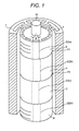
- Fig. 1 is a drawing showing an embodiment of a rotor and a stator 7 in an example of a permanent magnet motor of an electric motor 100 of the present invention.
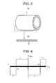
- Fig. 3 shows a conceptual diagram of the stator core (stator) 7, and Fig. 3(a) shows the cylindrical shape, and Fig. 3(b) shows the section 8 thereof.
- the core of the rotor 1 is composed of laminated steel plates and the laminated steel plates are divided into a plurality of blocks in the axial direction, that is, rotor pieces.
- the permanent magnets 2 respectively have an effective pole opening angle of ⁇ .
- the permanent magnets 2 having the effective pole opening angle are embedded in the core of the rotor 1, though as shown in Fig. 16, the permanent magnets may be attached to the core surfaces of the rotor 1. Further, the effective pole opening angle may be realized by magnetizing a ring magnet.
- the axial length and the phase difference of electrical angle which is decided by the position of the effective pole opening angle in the circumferential direction of the rotor pieces 3, 4, 5, and 6 and is decided by the following conception.
- the present invention uses a combination pattern of the axial length and the phase difference of the electrical angle when harmonic components of the electromagnetic exciting force, generated by the electrical characteristic, are orthogonalized with the longitudinal deformation modes of the stator core 7.
- a structural consists of only the stator core 7, and the axial length of the stator core 7 is the same as the core axial length of the rotor 1 such as 2L, and the boundary condition of the stator core 7 is both ends free or both ends fixed, and the stator core 7 is a beam, and the axial length of the rotor pieces 3, 4, 5, and 6 is the same as that of the permanent magnets 2 included in the rotor pieces 3, 4, 5, and 6.
- the axial length 2L does not include the axial length of the end plates.
- stator core 7 is assumed as a one-dimensional beam parallel to the x-axis and the force exiting the stator core 7 is assumed as one-dimensional force in the y-axis direction.
- the axial length of the stator core 7 is set to 2L.
- the one-dimensional beam is divided into four parts so as to be symmetrical about the central point O of the x-axis of the stator.
- the forces exiting each part symmetrical about the point O, for example, and their ampritudes are set to f and -f (f is a constant).
- This is a constitution that electromagnetic exciting force having the practically same amplitude in the radial direction is applied to each piece.
- Formulas 1 and 2 are satisfied and furthermore Formula 3 indicated below is considered to be satisfied.
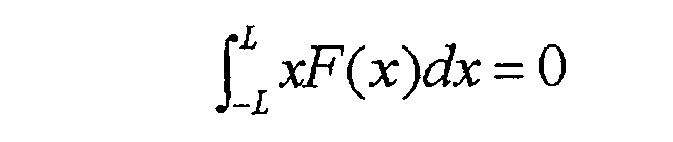
- Formula 1 sets the integral value to 0 and suppresses the longitudinal bending deformation mode order 0
- Formula 2 sets the point symmetrical vibration to 0 and suppresses the longitudinal bending deformation mode order 2.
- Formula 3 sets the moment value to 0 and suppresses the longitudinal bending deformation mode order 1.
- the number of divided pieces is plural and even such as four or more particularly from the obtained solution.
- stator core 7 has a cylindrical surface and the exiting force is three-dimensional electromagnetic exciting force in the radial direction of the circular mode order n whose center is the x-axis.
- the rotor 1 is divided into the rotor pieces 3, 4, 5, and 6 having an axial length of: Formula 8 ( 1 ⁇ 1 2 ) L , 1 2 L , 1 2 L , ( 1 ⁇ 1 2 ) L and the neighboring rotor pieces are shifted in the circumferential direction so as to set the phase differences of the respective electrical angles to 0, ⁇ , 0, and ⁇ , and the permanent magnets 2 are positioned in the circumferential direction, thus the moment applied to the stator core 7 ideally becomes 0, and the beam bending deformation modes order 0, 1, and 2 can be suppressed.
- each one pole of the effective pole opening angle of the rotor is divided into four pieces respectively for the axial length 2L of the rotor core, and the ideal four pieces have an axial length of 0.29L, 0.71L, 0.71L, and 0.29L, and the pieces are arranged in the circumferential direction as the phase difference of the electrical angles of the neighboring pieces equivalent to 0, ⁇ , 0, and ⁇ .
- the axial length error of the four pieces of the effective pole opening angle aforementioned can be set within the range of ⁇ 5% of the total axial length of one group of the four pieces of the rotor core.
- each one pole of the effective pole opening angle of the rotor is equally divided into six pieces respectively for the axial length 2L of one group of the rotor core, and the pieces can be arranged in the circumferential direction as the phase difference of the electrical angle of the neighboring pieces equivalent to 0, ⁇ , ⁇ ., 0, 0, and ⁇ .
- the means capable obtaining better results than the cases of no division case A, C and G shown in Fig. 7 and not meating the aforementioned three formulas is described.
- the effective pole opening angles are arranged in the circumferential direction as the phase difference of electrical angles of the neighboring pieces equivalent to 0, ⁇ , 0, and ⁇ . Further, the position in the circumferential direction is relative, so that ⁇ , 0, ⁇ , and 0 are equivalent to the aforementioned.
- phase difference of the electrical angle to n it may be considered to shift respectively the positions of the permanent magnets 2 in the circumferential direction by one half of the slot.
- Two shifting ways may be considered as shown in Figs. 1 and 13. The two ways may be selected from the viewpoint of motor efficiency and manufacture easiness.
- the axial length of the divided pieces in the arrangement order is 0.25L, 0.50L, 0.25L, 0.25L, 0.50L, and 0.25L.
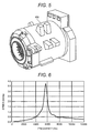
- the calculation model of the electric motor 100 uses the calculation model of the electric motor 100 shown in Fig. 5, the frequency response diagram of the average vibration velocity exited by the radial force of the circularmode order 0, when the rotor 1 is not divided, is shown in Fig. 6.
- the calculation model of the electric motor 100 has an external surface composed of a front bracket, a rear bracket, and a frame.
- the stator core 7 is inserted into the frame using the shrinkage fitting method.
- the rotor 1 is installed inside the electric motor 100 via bearings fitted into the brackets.
- the frequency response has a peak at 5645 Hz.
- the peak amplitude of the average vibration velocity of the electric motor 100 are shown in Fig. 7, when the electromagnetic radial force pattern is changed and the electromagnetic radial force exciting the stator core, is the circular mode order 0, and the amplitude of the electromagnetic radial force is same in the longitudinal direction.
- the results show that the average vibration velocity when the stator core 7 is excited in Case D shown in Fig. 2 is reduced by about 25 dB in a case of no division and by 15 dB in Case C that the rotor 1 is equally divided into four parts and the phase difference of the electrical angle of each piece is set to 0, ⁇ , 0, and ⁇ .
- Fig. 8 is a drawing showing calculation results of the average vibration velocity when a gear reducer is attached to the electric motor 100.
- Fig. 8 shows that the average vibration velocity of Case D for the electromagnetic exciting force is lower than the values of the other electromagnetic exciting force in the radial direction patterns and even if the gear reducer is attached, the vibration reduction effect is obtained.
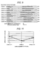
- the number of mesh divisions of the mesh diagrams 81 of the section of the stator core in the axial direction is set to 20 (Fig. 9).
- the calculation results of the peak of the average vibration velocity when the switching position of a phase difference of 0 or ⁇ is changed by ⁇ 0.1L in the axial direction on the basis of Case D are shown in Figs. 10, 11, and 12 and the switching patterns are shown in Fig. 9.
- Fig. 9 is a diagram showing the position for switching the phase difference in the mesh diagrams 81 of the section of the stator core in the axial direction.
- Fig. 10 is a diagram showing calculation results of the average vibration velocity by changing the position for switching the phase difference of the electromagnetic exciting force in the radial direction of Case D.
- FIG. 11 is a diagram showing calculation results of the average vibration velocity by shifting the position P1 (refer to Fig. 1) for switching the phase difference of the electromagnetic exciting force in the radial direction of Case D.
- Fig. 12 is a diagram showing calculation results of the average vibration velocity by shifting the position P2 for switching the phase difference of the electromagnetic exciting force in the radial direction of Case D.
- Figs. 10, 11, and 12 show that the switching positions of the phase differences 0 and ⁇ of the electrical angle of Case D are optimal points. Further, even if the switching positions of the phase differences 0 and ⁇ are changed by ⁇ 5% of the axial length, an vibration reduction effect is obtained, and in every switching pattern, the average vibration velocity is reduced by 11 dB or more compared with the case of no division.
- the switching positions of the phase differences 0 and n include at least ⁇ 5% of changes.
- Fig. 14 shows another embodiment.
- the rotor 1 is divided into 6 pieces of rotor pieces 3, 4a, 4b, 5a, 5b, and 6 having the same axial length (1/3L) and the phase difference of the electrical angle between the permanent magnet 2a having the effective magnetic pole opening angle ⁇ of the rotor piece 3, the permanent magnet 2b having the effective pole opening angle ⁇ of the rotor pieces 4a and 4b, the permanent magnets 2c having the effective magnetic pole opening angle ⁇ of the rotor pieces 5a and 5b, and the permanent magnets 2d having the effective magnetic pole opening angle ⁇ of the rotor pieces 6 is set to 0, ⁇ , 0, and ⁇ .
- the rotor pieces 3, 4a, 4b, 5a, 5b, and 6 can be formed with the same axial length and the preparation cost can be decreased. Further, this is a constitution within the division range in the axial direction producing the vibration reduction effect.
- the rotor 1 with an axial length of 2L is equally divided into four rotor pieces and assuming the phase difference of the electrical angle of each piece as 0, ⁇ ., 0, and ⁇ , the axial direction as the X-axis, and the range of x as -L ⁇ x ⁇ L, a constitution that the amplitude of the electromagnetic exciting force at the range of X as in the radial direction -L/2 ⁇ x ⁇ 0 and 0 ⁇ x ⁇ L/2 close to the central point O of the X-axis is 3 times (a multiple of the set reference exciting force) of the amplitude of the electromagnetic exciting force in the radial direction at the range of X as -L ⁇ x ⁇ L and -L/2 ⁇ x ⁇ L meets Formulas 1, 2 and 3.
- the electric motor is structured so as to arrange the effective pole opening angles of each piece at an angle shifted by one half of the slot between the pieces.
- the rotor or stator is divided into 4 or 4n (n indicates an integer, 4 forms one group) pieces in the axial direction, and assuming the axial length of one group of the rotor core or stator core as 2L, the amplitude of the electromagnetic exciting force in the radial direction practically same in the axial direction of each piece, and each piece of one group of four pieces, as an equivalent axial length, is set to any axial length within the range from 0.19L, 0.81L, 0.81L, and 0.19L to 0.39L, 0.61L, 0.61L, and 0.39L, and the effective pole opening angles are arranged in the circumferential direction as the phase difference of electrical angles of the neighboring pieces equivalent to 0, ⁇ , 0, and ⁇ .
- the rotor and/or stator is divided into 4 or 4n (n indicates an integer, 4 forms one group) pieces in the axial direction, and the amplitude of the electromagnetic exciting force in the radial directionpractically same the axial direction of each piece, and each piece of one group of four pieces, as an equivalent axial length, on the basis of 1:2:2:1, is set to any axial length within the range of ⁇ 5% of the total axial length of one group of the four pieces, and the effective pole opening angles are arranged in the circumferential direction as the phase difference of electrical angles of the neighboring pieces equivalent to 0, ⁇ ., 0, and ⁇ .
- the rotor or stator is divided into 6 or 6n (n indicates an integer, 6 forms one group) pieces in the axial direction, and assuming the axial length of one group of the rotor core or stator core as 2L, the amplitude of the electromagnetic exciting force in the radial direction practically same in the axial direction of each piece, and each piece of one group of six pieces, as an equivalent axial length, on the basis of 0.25L, 0.50L, 0.25L, 0.25L, 0.50L, and 0.25L, is set to any axial length within the range of ⁇ 5% of the total axial length of one group of the six pieces, and the effective pole opening angles are arranged in the circumferential direction as the phase difference of electrical angles of the neighboring pieces equivalent to 0, ⁇ , 0, and ⁇ .
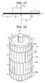
- the electromagnetic exciting force pattern can be applied not only to the permanent magnet motor but also to the synchronous reluctance motor shown in Fig. 18, the switched reluctance motor shown in Fig. 17, and the brushless DC motor shown in Fig. 19. Therefore, a magnet other than a permanent magnet can be used and for example, an electromagnet is available.
- stator core 7 is divided into four pieces such as stator core pieces 71, 72, 73, and 74. Even if the stator core 7 is divided like this, the same effect can be obtained.
- the present invention can be applied to a linear motor.
- the rotor 1 is cut off at one point and the cylindrical face is developed to a plane.
- the electromagnetic exciting force in the radial direction cuts off a part of the circular mode at one point and the cylindrical face is developed to a plane.
- the electric motor of the present invention is effective in reducing, among vibration and noise caused by the drive operation, vibration and noise of the motor excited by the electromagnetic electromagnetic exciting force in the radial direction.
Landscapes
- Engineering & Computer Science (AREA)
- Power Engineering (AREA)
- Iron Core Of Rotating Electric Machines (AREA)
- Permanent Field Magnets Of Synchronous Machinery (AREA)
- Permanent Magnet Type Synchronous Machine (AREA)
Abstract
Description
- The present invention relates to an electric motor and more particularly to a structure for suppressing generation of electromagnetic vibration and noise caused by electromagnetic exciting force in the radial direction of an inverter motor.
- Many electric motors are used in household electric appliances and various office automation devices and furthermore in recent years, have been loaded in electric cars.
- The motors are required for large output power, thus vibration and noise due to electromagnetic exciting force are caused.
- The electromagnetic exciting force in the radial direction is generated when, during mutual movement of a rotor and a stator, the electromagnetic path of magnetic field flux generated from the magnetic poles of the rotor is periodically changed whenever the magnetic poles of the rotor cross the openings of the slots formed on the stator and the magnetic flux distribution in the gap is changed. The time harmonic order, space harmonic order, and amplitude of the electromagnetic exciting force in the radial direction depend on the number of poles of the effective pole opening angle of the rotor and the number of slots formed in the stator.
- On the other hand, due to the pursuit of a comfortable environment in a house and a car, a request for reduction in vibration and noise is increased and arts for reducing them have been developed.
- As one of the arts for reducing vibration and noise, a skew is formed in the rotor of the electric motor. As a means for forming the skew, the following may be cited.
- In
Patent Document 1, the outer peripheral surface of the shaft is divided equally into several parts in the axial direction in the process of manufacturing the rotor by fixing the piece-shaped permanent magnets to the positions equally distributed on the outer peripheral surface, and the projections are formed on the outer peripheral surface of the shaft by pressing in the respective divided rows, and the permanent magnets are fixed using the projections for positioning the permanent magnets, and the skews are provided by attaching the balance weights to the tops of the projections when necessary, and insurance of positioning of the permanent magnets and skew angle, simplification of the steps, and reduction in the number of parts are realized. - In
Patent Document 2, the same poles of a plurality of ring permanent magnets multi-pole-magnetized in the axial direction are installed opposite to each other at a gap of t by forming a positioning slot in the motor shaft as a guide, thus the rotor magnet is structured so as to direct the magnetic flux lines in the radial direction, and the characteristic of the surface flux density is improved remarkably, and miniaturization and high performance of the motor are realized. - In
Patent Document 3, the magnet built-in rotor of the rotating machine is composed of a plurality of divided cylindrical bodies having a plurality of built-in permanent magnets so as to form magnetic poles whose polarity differs alternately in the rotational direction and a shaft for supporting the cylindrical bodies in a laminated state. The divided cylindrical bodies are laminated in the axial direction that the respective magnetic poles are shifted in the rotational direction, are fit into the shaft, are joined in the rotational direction, thereby are connected integrally with each other. By doing this, torque ripples are reduced, and the smooth rotation of the rotor is ensured, and a rotating machine can be obtained at a low cost. - In
Patent Document 4, in the brushless DC motor composed of the rotor having a mounted permanent magnets and the stator having a plurality of slots, the effective pole opening angle of the rotor is set to a value obtained by adding the angle equivalent to one slot opening to an integer times of the slot pitch of the stator, and the rotor is divided into several parts in the axial direction, and the divided parts of the rotor are structured so as to be shifted around the shaft by the mechanical angle equivalent to one half of the period regarding to the respective cogging torque. - Patent Document 1: Japanese Application Patent Laid-open No. Hei 6-245417
- Patent Document 2: Japanese Application Patent Laid-open No. 2000-245117
- Patent Document 3: Japanese Application Patent Laid-open No. 2000-308286
- Patent Document 4: Japanese Application Patent Laid-open No. 2001-359266
- However,
Patent Document 1 is effective in reduction in the cogging torque, reduction in the unbalance force, and reduction in the number of parts, though the effect in reduction in vibration and noise due to the electromagnetic exciting force in the radial direction is low. -
Patent Document 2 is also effective in reduction in the cogging torque, though it cannot be applied to a case that no gap can be formed, and no effect is obtained in reduction in vibration and noise due to the electromagnetic exciting force in the radial direction. -
Patent Document 3 is effective in reduction in torque ripples, though an effect is not always obtained in reduction in vibration and noise due to the electromagnetic exciting force in the radial direction. -
Patent Document 4 is effective in suppression of bending vibration of the rotation shaft induced by the cogging torque. However, an effect is not always obtained in suppression of the longitudinal bending deformation mode of the stator induced by the electromagnetic exciting force in the radial direction of an internal rotation motor. - An object of the present invention is to reduce vibration due to electromagnetic exciting force in the radial direction of an electric motor, thereby provide an electric motor of low noise.
- In the electric motor of the present invention, a rotor or a stator is divided into four or more even rotor pieces or stator pieces (although "divided" is specified here, a predetermined number of pieces seeming as divided is included) for an axial length of 2L. For each rotor piece or stator piece, so as to generate the electromagnetic exciting force in the radial direction orthogonalized with the longitudinal bending deformation modes of the stator, the axial length and the relative position in the circumferential direction of the effective pole opening angle included in each rotor piece or stator piece are decided.
- The rotor or stator is divided into 4 or 4n (n indicates an integer, 4 forms one group) pieces in the axial direction, and the length and electrical angle of each piece, assuming the axial length of one group of the rotor core or stator core as 2L, the axial direction as the X-axis, the axial center as x=0, and the electromagnetic exciting force in the radial direction as F(x), on the basis of the following three relational formulas:


- When the rotor or stator is divided into 4 (4n included) rotor pieces or stator pieces, the axial length of the four rotor pieces or stator pieces obtained ideally by the three formulas aforementioned is basically 0.29L, 0.71L, 0.71L, and 0.29L, and the equivalent axial length is set on the basis of the reference values, and the effective pole opening angle of one pole of the respective rotor pieces or stator pieces, so as to set the phase difference of the electrical angle between the respective rotor pieces or stator pieces in the circumferential direction of the rotor or stator to 0, π, 0, and π, is set to, for example, an angle shifted by one half of the slot between the pieces. At this time, the electrical angle used corresponds to the slot ripple component and one period (2π) is the slot pitch.
- When the rotor or stator is divided into 6 (6n included) rotor pieces or stator pieces, the axial length of the six rotor pieces or stator pieces obtained ideally by the three formulas aforementioned is set to 0.25L, 0.5L, 0.25L, 0.25L, 0.5L, and 0.25L and the rotor pieces or stator pieces are arranged in the setting order. And, the effective pole opening angle of one pole of the respective rotor pieces or stator pieces, so as to set the phase difference of the electrical angle between the respective rotor pieces or stator pieces in the circumferential direction of the rotor or stator to 0, π, 0, π, 0, and π, is set to, for example, an angle shifted by one half of the slot between the pieces.
-
- Fig. 1 is a drawing showing an embodiment of the rotor of the electric motor of the present invention,
- Fig. 2 is a drawing showing the exciting force pattern of the electric motor of the present invention and the orthogonal conditions which the electromagnetic exciting force in the radial direction must meet,
- Fig. 3 is a drawing showing the position relationship between the stator core and the cross section of the stator core in the axial direction,
- Fig. 4 is a drawing showing the exciting force pattern of the rotor pieces when the rotor core is divided into 4 pieces,
- Fig. 5 is a drawing of the electric motor used for analysis,
- Fig. 6 is a frequency response diagram of the avaradge vibration velocity excited by the electromagnetic force in the circular mode order(0) when the rotor is not divided,
- Fig. 7 is a diagram showing calculation results of the average vibration velocity of the electric motor by changing the electromagnetic radial force pattern,
- Fig. 8 is a diagram showing calculation results of the average vibrating velocity when a gear reducer is attached to the electric motor,
- Fig. 9 is a diagram showing the position for switching the phase difference in the mesh diagram of the section of the stator core in the axial direction,
- Fig. 10 is a diagram showing calculation results of the average vibration velocity by changing the position for switching the phase difference of the electromagnetic exciting force in the radial direction of Case D,
- Fig. 11 is a diagram showing calculation results of the average vibration velocity by shifting the position P1 for switching the phase difference of the electromagnetic exciting force of Case D,
- Fig. 12 is a diagram showing calculation results of the average vibration velocity by shifting the position P2 for switching the phase difference of the electromagnetic exciting force in the radial direction of Case D,
- Fig. 13 is a schematic view showing another embodiment of the present invention shown in Fig. 1,
- Fig. 14 is a schematic view showing still another embodiment of the present invention shown in Fig. 1,
- Fig. 15 is a schematic view showing another embodiment of the exciting force pattern of the rotor piece when the rotor core is divided into 4 pieces,
- Fig. 16 is a drawing showing an application example of the present invention shown in Fig. 1 to a surface magnet motor,
- Fig. 17 is a drawing showing an application example of the present invention shown in Fig. 1 to a switched reluctance motor,
- Fig. 18 is a drawing showing an application example of the present invention shown in Fig. 1 to a synchronous reluctance motor,
- Fig. 19 is a drawing showing an application example of the present invention shown in Fig. 1 to a brushless motor, and
- Fig. 20 is a drawing showing an application example of the present invention shown in Fig. 1 to a linear motor.
- Hereinafter, the embodiments of the present invention will be explained with reference to the accompanying drawings.
- Fig. 1 is a drawing showing an embodiment of a rotor and a
stator 7 in an example of a permanent magnet motor of anelectric motor 100 of the present invention. Fig. 3 shows a conceptual diagram of the stator core (stator) 7, and Fig. 3(a) shows the cylindrical shape, and Fig. 3(b) shows thesection 8 thereof. In these drawings, the core of therotor 1 is composed of laminated steel plates and the laminated steel plates are divided into a plurality of blocks in the axial direction, that is, rotor pieces. Therotor 1 shown in Fig. 1 is composed of fourrotor pieces shaft 10, and permanent magnets 2 (2a, 2b, 2c, 2d) having the same axial length as the axial length of therotor pieces permanent magnets 2 respectively have an effective pole opening angle of θ. - In Fig. 1, the
permanent magnets 2 having the effective pole opening angle are embedded in the core of therotor 1, though as shown in Fig. 16, the permanent magnets may be attached to the core surfaces of therotor 1. Further, the effective pole opening angle may be realized by magnetizing a ring magnet. - The axial length and the phase difference of electrical angle which is decided by the position of the effective pole opening angle in the circumferential direction of the
rotor pieces - The present invention uses a combination pattern of the axial length and the phase difference of the electrical angle when harmonic components of the electromagnetic exciting force, generated by the electrical characteristic, are orthogonalized with the longitudinal deformation modes of the
stator core 7. - Assuming the mode shapes of the
stator core 7 of theelectric motor 100, when the vibration and noise problem occurs as longitudinal bending deformation bending modes of thebeam order - For simple examination, a structural consists of only the
stator core 7, and the axial length of thestator core 7 is the same as the core axial length of therotor 1 such as 2L, and the boundary condition of thestator core 7 is both ends free or both ends fixed, and thestator core 7 is a beam, and the axial length of therotor pieces permanent magnets 2 included in therotor pieces rotor 1 has end plates, theaxial length 2L does not include the axial length of the end plates. - At this time, for the longitudinal bending deformation modes of the
beam order rotor pieces - For simple development of the formulas, as shown in Fig. 4, the
stator core 7 is assumed as a one-dimensional beam parallel to the x-axis and the force exiting thestator core 7 is assumed as one-dimensional force in the y-axis direction. The axial length of thestator core 7 is set to 2L. - The one-dimensional beam is divided into four parts so as to be symmetrical about the central point O of the x-axis of the stator. The forces exiting each part symmetrical about the point O, for example, and their ampritudes are set to f and -f (f is a constant). This is a constitution that electromagnetic exciting force having the practically same amplitude in the radial direction is applied to each piece.
- Assuming a function of force as F(x), by such division, the following conditional formulas are considered to be satisfied.


-
Formulas Formula 3 indicated below is considered to be satisfied. Here,Formula 1 sets the integral value to 0 and suppresses the longitudinal bendingdeformation mode order 0 andFormula 2 sets the point symmetrical vibration to 0 and suppresses the longitudinal bendingdeformation mode order 2.Formula 3 sets the moment value to 0 and suppresses the longitudinal bendingdeformation mode order 1. The number of divided pieces is plural and even such as four or more particularly from the obtained solution.

- The moment M applied to the one-dimensional beam is expressed by the following formula.

- The above formula is properly arranged as the following formula.

- Here, when the condition for the moment M = 0 is introduced, the following formula is obtained.

- When the above formula is solved, in a case of four divided pieces, the following relationship is held between x1 and L.

- The above relationship is held even if the
stator core 7 has a cylindrical surface and the exiting force is three-dimensional electromagnetic exciting force in the radial direction of the circular mode order n whose center is the x-axis. - Therefore, the
rotor 1 is divided into therotor pieces 
permanent magnets 2 are positioned in the circumferential direction, thus the moment applied to thestator core 7 ideally becomes 0, and the beam bendingdeformation modes order - However, in an actual electric motor, depending on the structure of the stator and conditions of constraint, the moment M does not become 0 perfectly, so that it should be noted.
- As mentioned above, basically, the rotor is divided into a plurality of pieces in the axial direction for each pole of the effective pole opening angle thereof, and the axial length and the electrical angle of each piece, assuming the axial length of one group of the rotor core as 2L, the axial direction as the x-axis, the axial center as x=0, and the electromagnetic exciting force in the radial direction as F(x), constitute an electric motor decided so as to hold the following three relational formulas:


- In the electric motor aforementioned, each one pole of the effective pole opening angle of the rotor is divided into four pieces respectively for the
axial length 2L of the rotor core, and the ideal four pieces have an axial length of 0.29L, 0.71L, 0.71L, and 0.29L, and the pieces are arranged in the circumferential direction as the phase difference of the electrical angles of the neighboring pieces equivalent to 0, π, 0, and π. - The axial length error of the four pieces of the effective pole opening angle aforementioned can be set within the range of ±5% of the total axial length of one group of the four pieces of the rotor core.
- In the electric motor aforementioned, each one pole of the effective pole opening angle of the rotor is equally divided into six pieces respectively for the
axial length 2L of one group of the rotor core, and the pieces can be arranged in the circumferential direction as the phase difference of the electrical angle of the neighboring pieces equivalent to 0, π, π., 0, 0, and π. - In the electric motor aforementioned, when each one pole of the effective pole opening angle of the rotor is divided into six pieces respectively for the
axial length 2L of one group of the rotor core, from the position of x=0, the six pieces, assuming the respective junction faces as -b, -a, 0, a, and b, meet:
- On the basis of the aforementioned formulas and solutions, the means capable obtaining better results than the cases of no division case A, C and G shown in Fig. 7 and not meating the aforementioned three formulas, is described. For example, in an electric motor composed of a rotor equipped with magnets and a stator having a plurality of slots, the rotor or stator is divided into 4 or 4n (n indicates an integer, 4 forms one group) pieces in the axial direction, and the axial length and the electrical angle of each piece, assuming the axial length of one group of the rotor core or stator core as 2L, the axial direction as the X-axis, the axial center as x=0, and the electromagnetic exciting force in the radial direction as F(x), on the basis of the following three relational formulas:



- Further, for example, in an electric motor composed of a rotor equipped with magnets and a stator having a plurality of slots, the rotor or stator is divided into 4 or 4n (n indicates an integer, 4 forms one group) pieces in the axial direction, and the axial length and the electrical angle of each piece, assuming the axial length of one group of the rotor core or stator core as 2L, the axial direction as the X-axis, the axial center as x=0, and the electromagnetic exciting force in the radial direction as F(x), on the basis of the following three relational formulas:


- As shown in Fig. 2, the effective pole opening angles are arranged in the circumferential direction as the phase difference of electrical angles of the neighboring pieces equivalent to 0, π, 0, and π. Further, the position in the circumferential direction is relative, so that π, 0, π, and 0 are equivalent to the aforementioned.
- As a means for setting the phase difference of the electrical angle to n, it may be considered to shift respectively the positions of the
permanent magnets 2 in the circumferential direction by one half of the slot. Two shifting ways may be considered as shown in Figs. 1 and 13. The two ways may be selected from the viewpoint of motor efficiency and manufacture easiness. - Further, even when the
rotor 1 is divided into six rotor pieces, the axial length can be decided similarly. This is equivalent to Case H shown in Fig. 2 which is a case meeting the aforementioned three formulas and in this case, between a and b shown in Fig. 2, the following relational formula is held.
- As a solution meeting the above formula, for example, there are a=0.25 and b=0.75 available.
- The axial length of the divided pieces in the arrangement order is 0.25L, 0.50L, 0.25L, 0.25L, 0.50L, and 0.25L.
- For example, as an effective range, in an electric motor composed of a rotor equipped with magnets and a stator having a plurality of slots, the rotor or stator is divided into 6 or 6n (n indicates an integer, 6 forms one group) pieces in the axial direction, and the axial length and the electrical angle of each piece, assuming the axial length of one group of the rotor core or stator core as 2L, the axial direction as the X-axis, the axial center as x=0, and the electromagnetic exciting force in the radial direction as F(x), on the basis of the following three relational formulas:


- Further, for example, in an electric motor composed of a rotor equipped with magnets and a stator having a plurality of slots, the rotor or stator is divided into 6 or 6n (n indicates an integer, 6 forms one group) pieces in the axial direction, and the axial length and the electrical angle of each piece, assuming the axial length of one group of the rotor core or stator core as 2L, the axial direction as the X-axis, the axial center as x=0, and the electromagnetic exciting force in the radial direction as F(x), on the basis of the following three relational formulas:


- Further, when the axial length is set to 2nL, assuming 4-piece division or 6-piece division as one group, for n times of the 4-piece division or 6-piece division, the same effect can be obtained. By the 4-piece division and 6-piece division, as aforementioned, Case D and Case H are obtained and the numbers of divided pieces are desirable for manufacture.
- Using the calculation model of the
electric motor 100 shown in Fig. 5, the frequency response diagram of the average vibration velocity exited by the radial force of thecircularmode order 0, when therotor 1 is not divided, is shown in Fig. 6. The calculation model of theelectric motor 100 has an external surface composed of a front bracket, a rear bracket, and a frame. Thestator core 7 is inserted into the frame using the shrinkage fitting method. Therotor 1 is installed inside theelectric motor 100 via bearings fitted into the brackets. The frequency response has a peak at 5645 Hz. - The peak amplitude of the average vibration velocity of the
electric motor 100 are shown in Fig. 7, when the electromagnetic radial force pattern is changed and the electromagnetic radial force exciting the stator core, is thecircular mode order 0, and the amplitude of the electromagnetic radial force is same in the longitudinal direction. The results show that the average vibration velocity when thestator core 7 is excited in Case D shown in Fig. 2 is reduced by about 25 dB in a case of no division and by 15 dB in Case C that therotor 1 is equally divided into four parts and the phase difference of the electrical angle of each piece is set to 0, π, 0, and π. On the basis of an ideal axial length and electrical angle arrangement obtained from theoretical formulas, the axial length and the electrical angle arrangement of a group of the aforementioned four pieces are decided, thus better results than Case C or G are obtained. Namely, the average vibration velocity is reduced by 11.5 dB or more, for example, by 15 dB or 20 dB. These reductions can be realized by setting the equivalent axial length shown in each example of this embodiment to each piece axial length of the group - Fig. 8 is a drawing showing calculation results of the average vibration velocity when a gear reducer is attached to the
electric motor 100. Fig. 8 shows that the average vibration velocity of Case D for the electromagnetic exciting force is lower than the values of the other electromagnetic exciting force in the radial direction patterns and even if the gear reducer is attached, the vibration reduction effect is obtained. - Next, the vibration response when the phase switching position is changed by several % will be examined.
- The number of mesh divisions of the mesh diagrams 81 of the section of the stator core in the axial direction is set to 20 (Fig. 9). The calculation results of the peak of the average vibration velocity when the switching position of a phase difference of 0 or π is changed by ±0.1L in the axial direction on the basis of Case D are shown in Figs. 10, 11, and 12 and the switching patterns are shown in Fig. 9. Fig. 9 is a diagram showing the position for switching the phase difference in the mesh diagrams 81 of the section of the stator core in the axial direction. Fig. 10 is a diagram showing calculation results of the average vibration velocity by changing the position for switching the phase difference of the electromagnetic exciting force in the radial direction of Case D. Fig. 11 is a diagram showing calculation results of the average vibration velocity by shifting the position P1 (refer to Fig. 1) for switching the phase difference of the electromagnetic exciting force in the radial direction of Case D. Fig. 12 is a diagram showing calculation results of the average vibration velocity by shifting the position P2 for switching the phase difference of the electromagnetic exciting force in the radial direction of Case D. Figs. 10, 11, and 12 show that the switching positions of the
phase differences 0 and π of the electrical angle of Case D are optimal points. Further, even if the switching positions of thephase differences 0 and π are changed by ±5% of the axial length, an vibration reduction effect is obtained, and in every switching pattern, the average vibration velocity is reduced by 11 dB or more compared with the case of no division. The switching positions of thephase differences 0 and n include at least ±5% of changes. - Therefore, even if the axial lengths of the
rotor pieces - As mentioned above, in an electric motor composed of a rotor equipped with a magnet and a stator having a plurality of slots, the rotor or stator is divided into 4 or 4n (n indicates an integer, 4 forms one group) pieces in the axial direction, and the axial length and the electrical angle of each piece, assuming the axial length of one group of the rotor core or stator core as 2L, the axial direction as the X-axis, the axial center as x=0, and the electromagnetic exciting force in the radial direction as F(x), on the basis of the following three relational formulas:



- Thus far, for the harmonic component of the electromagnetic exiting force of the
circular mode order 0, the vibration reduction effect of the electromagnetic exciting force pattern in the radial direction of Case D has been examined, though for the harmonic component of the electromagnetic exiting force of the circular mode another order, the similar results can be obtained. - Fig. 14 shows another embodiment. In this embodiment, on the assumption that the three formulas aforementioned are satisfied, the
rotor 1 is divided into 6 pieces ofrotor pieces permanent magnet 2a having the effective magnetic pole opening angle θ of therotor piece 3, thepermanent magnet 2b having the effective pole opening angle θ of therotor pieces permanent magnets 2c having the effective magnetic pole opening angle θ of therotor pieces permanent magnets 2d having the effective magnetic pole opening angle θ of therotor pieces 6 is set to 0, π, 0, and π. By use of this constitution, therotor pieces - The case that the electromagnetic exciting force in the axial direction having a same amplitude in the axial direction is applied is described above. This concept can be applied also to a case that the division width of the axial length is fixed and the amplitude of the electromagnetic exciting force in the radial direction is changed in the axial direction. For example, as shown in Fig. 15, the
rotor 1 with an axial length of 2L is equally divided into four rotor pieces and assuming the phase difference of the electrical angle of each piece as 0, π., 0, and π, the axial direction as the X-axis, and the range of x as -L ≤ x ≤ L, a constitution that the amplitude of the electromagnetic exciting force at the range of X as in the radial direction -L/2 ≤ x ≤ 0 and 0 ≤ x ≤ L/2 close to the central point O of the X-axis is 3 times (a multiple of the set reference exciting force) of the amplitude of the electromagnetic exciting force in the radial direction at the range of X as -L ≤ x ≤ L and -L/2 ≤ x ≤ L meetsFormulas - Therefore, synthetically, in an electric motor composed of a rotor equipped with magnets and a stator having a plurality of slots, the rotor or stator is divided into even pieces such as 4 pieces or more in the axial direction, and the axial length and electrical angle of each piece, assuming the axial length of one group of the rotor core or stator core as 2L, the axial direction as the X-axis, the axial center as x=0, and the electromagnetic exciting force in the radial direction as F(x), on the basis of the following three relational formulas:



- In any of the aforementioned examples, the electric motor is structured so as to arrange the effective pole opening angles of each piece at an angle shifted by one half of the slot between the pieces.
- As an actual embodiment, in an electric motor composed of a rotor equipped with magnets and a stator having a plurality of slots, the rotor or stator is divided into 4 or 4n (n indicates an integer, 4 forms one group) pieces in the axial direction, and assuming the axial length of one group of the rotor core or stator core as 2L, the amplitude of the electromagnetic exciting force in the radial direction practically same in the axial direction of each piece, and each piece of one group of four pieces, as an equivalent axial length, is set to any axial length within the range from 0.19L, 0.81L, 0.81L, and 0.19L to 0.39L, 0.61L, 0.61L, and 0.39L, and the effective pole opening angles are arranged in the circumferential direction as the phase difference of electrical angles of the neighboring pieces equivalent to 0, π, 0, and π.
- Further, in an electric motor composed of a rotor equipped with magnets and a stator having a plurality of slots, the rotor and/or stator is divided into 4 or 4n (n indicates an integer, 4 forms one group) pieces in the axial direction, and the amplitude of the electromagnetic exciting force in the radial directionpractically same the axial direction of each piece, and each piece of one group of four pieces, as an equivalent axial length, on the basis of 1:2:2:1, is set to any axial length within the range of ±5% of the total axial length of one group of the four pieces, and the effective pole opening angles are arranged in the circumferential direction as the phase difference of electrical angles of the neighboring pieces equivalent to 0, π., 0, and π.
- Further, in an electric motor composed of a rotor equipped with magnets and a stator having a plurality of slots, the rotor or stator is divided into 6 or 6n (n indicates an integer, 6 forms one group) pieces in the axial direction, and assuming the axial length of one group of the rotor core or stator core as 2L, the amplitude of the electromagnetic exciting force in the radial direction practically same in the axial direction of each piece, and each piece of one group of six pieces, as an equivalent axial length, on the basis of 0.25L, 0.50L, 0.25L, 0.25L, 0.50L, and 0.25L, is set to any axial length within the range of ±5% of the total axial length of one group of the six pieces, and the effective pole opening angles are arranged in the circumferential direction as the phase difference of electrical angles of the neighboring pieces equivalent to 0, π, 0, and π.
- Further, the electromagnetic exciting force pattern can be applied not only to the permanent magnet motor but also to the synchronous reluctance motor shown in Fig. 18, the switched reluctance motor shown in Fig. 17, and the brushless DC motor shown in Fig. 19. Therefore, a magnet other than a permanent magnet can be used and for example, an electromagnet is available.
- Furthermore, in the brushless DC motor shown in Fig. 19, the
magnets 2 is arranged in thestator core 7. Thestator core 7 is divided into four pieces such asstator core pieces stator core 7 is divided like this, the same effect can be obtained. - Further, as shown in Fig. 20, the present invention can be applied to a linear motor. At this time, it may be considered that the
rotor 1 is cut off at one point and the cylindrical face is developed to a plane. At this time, it may be considered that the electromagnetic exciting force in the radial direction cuts off a part of the circular mode at one point and the cylindrical face is developed to a plane. - The electric motor of the present invention is effective in reducing, among vibration and noise caused by the drive operation, vibration and noise of the motor excited by the electromagnetic electromagnetic exciting force in the radial direction.
Claims (11)
- An electric motor comprising a rotor equipped with magnets and a stator having a plurality of slots, wherein:said rotor or said stator is divided into 4 or 4n (n indicates an integer, 4 forms one group) pieces in an axial direction, and an axial length and an electrical angle of said each piece, assuming an axial length of said one group of said rotor core or said stator core as 2L, said axial direction as a X-axis, an axial center as x=0, and electromagnetic exciting force in a radial direction as F(x), on the basis of following three relational formulas:


 said each piece of said one group of said four pieces, as said equivalent axial length, is set to any axial length within a range from 0.19L, 0.81L, 0.81L, and 0.19L to 1/2L, 1/2L, 1/2, and 1/2L, and effective pole opening angles are arranged in the circumferential direction as a phase difference of electrical angles of said neighboring pieces equivalent to 0, π, 0, and π.
 - An electric motor comprising a rotor equipped with magnets and a stator having a plurality of slots, wherein:said rotor or said stator is divided into 4 or 4n (n indicates an integer, 4 forms one group) pieces in an axial direction, and an axial length and an electrical angle of said each piece, assuming an axial length of said one group of said rotor core or said stator core as 2L, said axial direction as a X-axis , an axial center as x=0, and electromagnetic exciting force in a radial direction as F(x), on the basis of following three relational formulas:


 said each piece of said one group of said four pieces, as said equivalent axial length, is set to any axial length within a range from 0.19L, 0.81L, 0.81L, and 0.19L to 0.39L, 0.61L, 0.61L, and 0.39L, and effective pole opening angles are arranged in a circumferential direction as phase difference of electrical angles of said neighboring pieces equivalent to 0, π, 0, and π.
 - An electric motor comprising a rotor equipped with magnets and a stator having a plurality of slots, wherein:said rotor or said stator is divided into 4 or 4n (n indicates an integer, 4 forms one group) pieces in an axial direction, and an axial length and an electrical angle of said each piece, assuming an axial length of said one group of said rotor core or said stator core as 2L, said axial direction as a K-axis, an axial center as x=0, and electromagnetic exciting force in a radial direction as F(x), on the basis of following three relational formulas:


 said each piece of said one group of said four pieces, as said equivalent axial length, on the basis of 1:2:2:1, is set to any axial length within a range of ±5% of a total axial length of said one group of said four pieces, and effective pole opening angles are arranged in the circumferential direction as a phase difference of electrical angles of said neighboring pieces equivalent to 0, n, 0, and π.
 - An electric motor comprising a rotor equipped with magnets and a stator having a plurality of slots, wherein:said rotor or said stator is divided into 6 or 6n (n indicates an integer, 6 forms one group) pieces in an axial direction, and an axial length and an electrical angle of said each piece, assuming an axial length of said one group of said rotor core or said stator core as 2L, said axial direction as a X-axis , an axial center as x=0, and electromagnetic exciting force in a radial direction as F(x), on the basis of following three relational formulas:


 said each piece of said one group of said six pieces, as said equivalent length, on the basis of 0.25L, 0.50L, 0.25L, 0.25L, 0.50L, and 0.25L, is set to any axial length within a range of ±5% of a total axial length of said one group of said six pieces,or within a range from 0.25L, 0.50L, 0.25L, 0.25L, 0.50L, and 0.25L to 1/3L, 1/3L, 1/3L, 1/3L, 1/3L, and 1/3L, and effective pole opening angles are arranged in the circumferential direction as a phase difference of electrical angles of said neighboring pieces equivalent to 0, π, 0, and π.
 - An electric motor comprising a rotor equipped with magnets and a stator having a plurality of slots, wherein:said rotor or said stator is divided into 6 or 6n (n indicates an integer, 6 forms one group) pieces in an axial direction, and a longitudinal length and an electrical angle of said each piece, assuming an axial length of said one group of said rotor core or said stator core as 2L, said axial direction as a X-axis, an axial center as x=0, and electromagnetic exciting force in a radial direction as F(x), on the basis of following three relational formulas:

 said each piece of said one group of said six pieces, as said equivalent length, on the basis of 0.25L, 0.50L, 0.25L, 0.25L, 0.50L, and 0.25L, is set to any axial length within a range of ±5% of a total axial length of said one group of said six pieces, and effective pole opening angles are arranged in the circumferential direction as a phase difference of electrical angles of said neighboring pieces equivalent to 0, π., 0, and π.
 - An electric motor comprising a rotor equipped with magnets and a stator having a plurality of slots, wherein:said rotor or said stator is divided into even pieces such as 4 pieces or more in an axial direction, and an axial length and an electrical angle of said each piece, assuming an axial length of said rotor core or said stator core as 2L, said axial direction as a X-axis, an axial center as x=0, and electromagnetic exciting force in a radial direction as F(x), on the basis of following three relational formulas:


- An electric motor comprising a rotor equipped with magnets and a stator having a plurality of slots, wherein:said rotor or said stator is divided into 4 or 4n (n indicates an integer, 4 forms one group) pieces in an axial direction, and electromagnetic exciting force in a radial direction having a practically same amplitude is applied to said each piece, andassuming an axial length of said one group of said rotor or said stator as 2L, said each piece of said one group of said four pieces, as an equivalent axial length, is set to any axial length within a range from 0.19L, 0.81L, 0.19L, 0.81L to 0.39L, 0.61L, 0.61L, and 0.39L, and effective pole opening angles are arranged in the circumferential direction as a phase difference of electrical angles of said neighboring pieces equivalent to 0, π, 0, and π.
- An electric motor composed of a rotor equipped with magnets and a stator having a plurality of slots, wherein:said rotor or said stator is divided into 4 or 4n (n indicates an integer, 4 forms one group) pieces in an axial direction, and electromagnetic exciting force having a practically same amplitude in a radial direction is applied to said each piece, andsaid each piece of said one group of said four pieces, as an equivalent axial length, on the basis of 1:2:2:1, is set to any axial length within a range of ±5% of a total axial length of said one group of said four pieces, and effective pole opening angles are arranged in the circumferential direction as a phase difference of electrical angles of said neighboring pieces equivalent to 0, π, 0, and π.
- An electric motor comprising a rotor equipped with magnets and a stator having a plurality of slots, wherein:said rotor or said stator is divided into 6 or 6n (n indicates an integer, 6 forms one group) pieces in an axial direction, and electromagnetic exciting force in a radial direction having a practically same amplitude is applied to said each piece, andassuming an axial length of said one group of said rotor or said stator as 2L, said each piece of said one group of said six pieces, as said equivalent axial length, on the basis of 0.25L, 0.50L, 0.25L, 0.25L, 0.50L, and 0.25L, is set to any axial length within a range of ±5% of a total axial length of said one group of said six pieces, and effective pole opening angles are arranged in the circumferential direction as a phase difference of electrical angles of said neighboring pieces equivalent to 0, π, 0, and π.
- An electric motor according to any of Claims 1 to 9, wherein said effective pole opening angles of said each piece are set to an angle shifted by one half of said slot between said pieces.
- An electric motor according to any of Claims 1 to 10, wherein when said electric motor is a linear motor, said rotor and said stator are in a shape developed on a plane.
Applications Claiming Priority (2)
| Application Number | Priority Date | Filing Date | Title |
|---|---|---|---|
| JP2003151917A JP4270942B2 (en) | 2003-05-29 | 2003-05-29 | Electric motor |
| PCT/JP2004/007592 WO2004107529A1 (en) | 2003-05-29 | 2004-05-26 | Electric motor |
Publications (3)
| Publication Number | Publication Date |
|---|---|
| EP1628381A1 true EP1628381A1 (en) | 2006-02-22 |
| EP1628381A4 EP1628381A4 (en) | 2009-11-11 |
| EP1628381B1 EP1628381B1 (en) | 2013-10-16 |
Family
ID=33487243
Family Applications (1)
| Application Number | Title | Priority Date | Filing Date |
|---|---|---|---|
| EP04734928.7A Expired - Lifetime EP1628381B1 (en) | 2003-05-29 | 2004-05-26 | Electric motor |
Country Status (6)
| Country | Link |
|---|---|
| US (1) | US7518277B2 (en) |
| EP (1) | EP1628381B1 (en) |
| JP (1) | JP4270942B2 (en) |
| KR (1) | KR100751992B1 (en) |
| CN (1) | CN1799176B (en) |
| WO (1) | WO2004107529A1 (en) |
Cited By (4)
| Publication number | Priority date | Publication date | Assignee | Title |
|---|---|---|---|---|
| WO2008143976A3 (en) * | 2007-05-17 | 2009-03-12 | Kurz Kasch Inc | Permanent magnet motor including a double rotor |
| WO2009144158A1 (en) * | 2008-05-29 | 2009-12-03 | Robert Bosch Gmbh | Kit for pole magnets, pole magnet and electrical machine |
| US7825560B2 (en) | 2007-03-08 | 2010-11-02 | Lg Electronics Inc. | Motor |
| WO2013143785A3 (en) * | 2012-03-30 | 2014-07-03 | Bayerische Motoren Werke Aktiengesellschaft | Vibration prevention in synchronous machines |
Families Citing this family (50)
| Publication number | Priority date | Publication date | Assignee | Title |
|---|---|---|---|---|
| JP4894273B2 (en) * | 2005-01-21 | 2012-03-14 | 株式会社日立製作所 | Rotating electric machine |
| US7541710B2 (en) | 2005-01-21 | 2009-06-02 | Hitachi, Ltd. | Rotating electric machine |
| JP4793748B2 (en) * | 2005-02-22 | 2011-10-12 | コニカミノルタオプト株式会社 | Spindle device |
| JP4637714B2 (en) * | 2005-10-13 | 2011-02-23 | 三菱電機株式会社 | Permanent magnet rotating electric machine |
| JP4376863B2 (en) * | 2005-12-22 | 2009-12-02 | シナノケンシ株式会社 | Permanent magnet type rotating machine |
| DE102006052772A1 (en) * | 2006-03-20 | 2007-09-27 | Temic Automotive Electric Motors Gmbh | Rotor for a permanent-magnet motor, in particular EC motor |
| JP4404086B2 (en) * | 2006-11-22 | 2010-01-27 | ダイキン工業株式会社 | Rotor and rotating machine |
| JP4908178B2 (en) * | 2006-12-15 | 2012-04-04 | 東芝産業機器製造株式会社 | Rotating electric machine |
| JP2008228390A (en) * | 2007-03-09 | 2008-09-25 | Jtekt Corp | Brushless motor and electric power steering apparatus having the same |
| JP4701269B2 (en) * | 2008-02-08 | 2011-06-15 | 本田技研工業株式会社 | Magnetic machine |
| JP5058849B2 (en) * | 2008-03-05 | 2012-10-24 | 株式会社ミツバ | Brushless motor |
| EP2139100B1 (en) * | 2008-06-27 | 2012-10-31 | Siemens Aktiengesellschaft | Permanent magnet synchronous machine with reduced cogging torque |
| JP5433198B2 (en) * | 2008-10-16 | 2014-03-05 | 日立オートモティブシステムズ株式会社 | Rotating electric machines and electric vehicles |
| US8536748B2 (en) * | 2008-11-11 | 2013-09-17 | Ford Global Technologies, Llc | Permanent magnet machine with different pole arc angles |
| US20100117475A1 (en) * | 2008-11-11 | 2010-05-13 | Ford Global Technologies, Llc | Permanent Magnet Machine with Offset Pole Spacing |
| JP5305887B2 (en) * | 2008-12-18 | 2013-10-02 | 株式会社東芝 | Permanent magnet rotating electric machine |
| TWI408868B (en) * | 2008-12-19 | 2013-09-11 | Ind Tech Res Inst | A rotating electric machine with complementary permanent magnet structure to minimize cogging torque |
| JP5581013B2 (en) * | 2009-06-23 | 2014-08-27 | 株式会社三井ハイテック | Rotor core |
| US8482243B2 (en) * | 2010-03-25 | 2013-07-09 | Gerald K. Langreck | High acceleration rotary actuator |
| DE102010032764A1 (en) * | 2010-07-29 | 2012-02-02 | Feaam Gmbh | Electric machine and stator for the same |
| JP5760744B2 (en) * | 2011-06-28 | 2015-08-12 | 日産自動車株式会社 | Rotating electric machine |
| JP5990886B2 (en) * | 2011-09-22 | 2016-09-14 | 日産自動車株式会社 | Rotor |
| JP5722183B2 (en) * | 2011-09-29 | 2015-05-20 | 本田技研工業株式会社 | Electric motor |
| US20130169099A1 (en) * | 2011-12-31 | 2013-07-04 | Danotek Motion Technologies, Inc. | Magnet assembly for permanent magnet machine |
| US9991772B2 (en) | 2011-12-31 | 2018-06-05 | Philip Totaro | Low axial force permanent magnet machine and magnet assembly for permanent magnet machine |
| JP5786804B2 (en) * | 2012-06-13 | 2015-09-30 | 株式会社デンソー | Rotor for rotating electrical machine and method for manufacturing the same |
| US20130342064A1 (en) * | 2012-06-22 | 2013-12-26 | Lg Innotek Co., Ltd. | Rotor and motor having the same |
| DE102012213465A1 (en) * | 2012-07-31 | 2014-02-06 | Brose Fahrzeugteile GmbH & Co. Kommanditgesellschaft, Würzburg | Permanent magnet synchronous motor and power steering assembly |
| JP5737250B2 (en) * | 2012-09-21 | 2015-06-17 | 株式会社デンソー | Rotor and rotating electric machine |
| US20150084467A1 (en) * | 2013-09-26 | 2015-03-26 | Tewari Paramahamsa | Reduced Reaction Rotary Alternating Current Generator |
| DE112014006129B4 (en) * | 2014-01-08 | 2025-05-22 | Mitsubishi Electric Corporation | Rotating electrical machine |
| DE102014222044A1 (en) * | 2014-10-29 | 2016-05-19 | Volkswagen Aktiengesellschaft | Rotor of an electric machine, electric machine and method of manufacturing a rotor of an electric machine |
| JP6427425B2 (en) * | 2015-01-19 | 2018-11-21 | 本田技研工業株式会社 | Rotor of rotary electric machine and method of manufacturing the same |
| US10003227B2 (en) * | 2015-03-20 | 2018-06-19 | GM Global Technology Operations LLC | Axially asymmetric configuration for interior permanent magnet machine |
| JP6101733B2 (en) * | 2015-04-20 | 2017-03-22 | 本田技研工業株式会社 | Rotating electrical machine rotor |
| US10003228B2 (en) | 2015-08-25 | 2018-06-19 | Wisconsin Alumni Research Foundation | Interior permanent magnet machine with axially varying permanent magnet size |
| CN105305684B (en) * | 2015-10-09 | 2018-05-11 | 清华大学 | A kind of magneto for reducing pole frequency and groove frequency radial direction electro-magnetic exciting force |
| CN108141076B (en) * | 2015-10-30 | 2020-02-21 | 日立汽车系统株式会社 | Magnet-type rotor, rotating electrical machine with magnet-type rotor, and electric vehicle with rotating electrical machine |
| JP6654902B2 (en) * | 2016-01-07 | 2020-02-26 | Ntn株式会社 | Rotary motor |
| ES2589155B1 (en) * | 2016-06-29 | 2017-08-17 | Centro De Investigaciones Energéticas, Medioambientales Y Tecnológicas (Ciemat) | PROCEDURE FOR OBTAINING A SWITCHED RELUCTANCE MACHINE WITH IMPROVED TORQUE |
| US11005312B2 (en) * | 2016-11-21 | 2021-05-11 | Unison Industries, Llc | Skewed stator designs for hybrid homopolar electrical machines |
| US11005313B2 (en) * | 2016-11-21 | 2021-05-11 | Unison Industries, Llc | Skewed rotor designs for hybrid homopolar electrical machines |
| CN107104564A (en) * | 2017-06-01 | 2017-08-29 | 深圳国安精密机电有限公司 | The transverse flux switched reluctance motor of multimode |
| IT201700100814A1 (en) * | 2017-09-08 | 2019-03-08 | S M E S P A | Procedure for the assembly of a rotor of a synchronous motor with variable reluctance and this rotor |
| US10886801B2 (en) | 2017-09-29 | 2021-01-05 | Wisconsin Alumni Research Foundation | Vernier machine with shaped permanent magnet groups |
| CN107947407A (en) * | 2017-11-16 | 2018-04-20 | 珠海格力节能环保制冷技术研究中心有限公司 | A kind of p-m rotor and magneto |
| US10873227B2 (en) * | 2017-11-30 | 2020-12-22 | Steering Solutions Ip Holding Corporation | Interior permanent magnet synchronous machine |
| EA202192064A1 (en) * | 2018-12-17 | 2021-11-24 | Ниппон Стил Корпорейшн | CORE AND ELECTRIC MOTOR |
| US11349358B2 (en) | 2019-07-11 | 2022-05-31 | Steering Solutions Ip Holding Corporation | Apparatus and method for an interior permanent magnet with rotor hybridization |
| JP6896029B2 (en) * | 2019-08-19 | 2021-06-30 | 三菱電機株式会社 | Rotating machine |
Family Cites Families (20)
| Publication number | Priority date | Publication date | Assignee | Title |
|---|---|---|---|---|
| JPS60181174A (en) | 1984-02-29 | 1985-09-14 | Hitachi Powdered Metals Co Ltd | Electromagnetic wave shielding coating compound |
| BG39783A1 (en) | 1984-05-08 | 1986-08-15 | Popov | Rotor with permanent magnets for electric machine |
| JPS60181174U (en) * | 1984-05-11 | 1985-12-02 | 東栄電機株式会社 | Rotating field electric machine |
| JPS60187117U (en) | 1984-05-22 | 1985-12-11 | 日立金属株式会社 | Work automatic alignment processing equipment |
| US4642502A (en) * | 1986-04-24 | 1987-02-10 | General Motors Corporation | Dynamoelectric machine with permanent magnet and magnet mounting surface arrangement |
| JP2672178B2 (en) * | 1990-05-15 | 1997-11-05 | ファナック株式会社 | Rotor structure of synchronous motor |
| US5397951A (en) * | 1991-11-29 | 1995-03-14 | Fanuc Ltd. | Rotor for a synchronous rotary machine |
| JP3304588B2 (en) | 1993-02-18 | 2002-07-22 | 株式会社安川電機 | Rotor with permanent magnet and manufacturing method thereof |
| JPH099602A (en) * | 1995-06-21 | 1997-01-10 | Toyoda Mach Works Ltd | Stepping motor |
| JPH1118339A (en) | 1997-06-27 | 1999-01-22 | Aisin Aw Co Ltd | Motor |
| JP3769943B2 (en) * | 1998-08-21 | 2006-04-26 | 松下電器産業株式会社 | Permanent magnet rotor |
| JP3541343B2 (en) | 1998-08-06 | 2004-07-07 | シャープ株式会社 | Rotor structure of synchronous machine, synchronous motor and synchronous generator |
| JP2000245117A (en) | 1998-12-21 | 2000-09-08 | Seiko Instruments Inc | Rotor magnet |
| JP2000278895A (en) | 1999-03-26 | 2000-10-06 | Nissan Motor Co Ltd | Motor rotor |
| JP2001190050A (en) * | 1999-04-01 | 2001-07-10 | Asmo Co Ltd | Rotating-field type motor |
| JP2000308286A (en) | 1999-04-16 | 2000-11-02 | Yamaha Motor Co Ltd | Rotating electric machine |
| JP4568941B2 (en) | 2000-02-16 | 2010-10-27 | パナソニック株式会社 | Permanent magnet rotor |
| JP2001314050A (en) * | 2000-04-27 | 2001-11-09 | Sony Corp | AC servo motor |
| JP4463947B2 (en) * | 2000-06-13 | 2010-05-19 | アイチエレック株式会社 | Structure of brushless DC motor |
| US6940198B2 (en) * | 2003-07-24 | 2005-09-06 | A. O. Smith Corporation | Brushless permanent magnet machine with reduced cogging and torque ripple and method of producing the same |
-
2003
- 2003-05-29 JP JP2003151917A patent/JP4270942B2/en not_active Expired - Lifetime
-
2004
- 2004-05-26 EP EP04734928.7A patent/EP1628381B1/en not_active Expired - Lifetime
- 2004-05-26 WO PCT/JP2004/007592 patent/WO2004107529A1/en not_active Ceased
- 2004-05-26 US US10/558,366 patent/US7518277B2/en not_active Expired - Lifetime
- 2004-05-26 CN CN2004800148821A patent/CN1799176B/en not_active Expired - Lifetime
- 2004-05-26 KR KR1020057022644A patent/KR100751992B1/en not_active Expired - Lifetime
Cited By (6)
| Publication number | Priority date | Publication date | Assignee | Title |
|---|---|---|---|---|
| US7825560B2 (en) | 2007-03-08 | 2010-11-02 | Lg Electronics Inc. | Motor |
| WO2008143976A3 (en) * | 2007-05-17 | 2009-03-12 | Kurz Kasch Inc | Permanent magnet motor including a double rotor |
| US7800276B2 (en) | 2007-05-17 | 2010-09-21 | Kurz-Kasch, Inc. | Rotor assembly |
| WO2009144158A1 (en) * | 2008-05-29 | 2009-12-03 | Robert Bosch Gmbh | Kit for pole magnets, pole magnet and electrical machine |
| WO2013143785A3 (en) * | 2012-03-30 | 2014-07-03 | Bayerische Motoren Werke Aktiengesellschaft | Vibration prevention in synchronous machines |
| US9876403B2 (en) | 2012-03-30 | 2018-01-23 | Bayerische Motoren Werke Aktiengesellschaft | Vibration prevention in synchronous machines |
Also Published As
| Publication number | Publication date |
|---|---|
| JP4270942B2 (en) | 2009-06-03 |
| CN1799176B (en) | 2012-04-18 |
| CN1799176A (en) | 2006-07-05 |
| US20070205689A1 (en) | 2007-09-06 |
| WO2004107529A1 (en) | 2004-12-09 |
| KR100751992B1 (en) | 2007-08-28 |
| EP1628381A4 (en) | 2009-11-11 |
| JP2004357405A (en) | 2004-12-16 |
| US7518277B2 (en) | 2009-04-14 |
| EP1628381B1 (en) | 2013-10-16 |
| KR20060013562A (en) | 2006-02-10 |
Similar Documents
| Publication | Publication Date | Title |
|---|---|---|
| EP1628381B1 (en) | Electric motor | |
| EP1684400B1 (en) | Rotating electric machine | |
| US8274182B2 (en) | Linear motor including extended tooth tips | |
| KR100720753B1 (en) | Permanent Magnet Synchronous Linear Motor | |
| JP4723118B2 (en) | Rotating electric machine and pulley drive device using the rotating electric machine | |
| US8446054B2 (en) | Periodic magnetic field generation device, and linear motor and rotary motor using the same | |
| JP3766358B2 (en) | Permanent magnet built-in motor rotor | |
| EP1511164B1 (en) | Linear motor with reduced cogging force | |
| CN103891102B (en) | Rotor, compressor and the refrigerating air conditioning device of permanent magnet embedded-type electric motivation | |
| EP1804365A2 (en) | Permanent magnet excited transverse flux motor with outer rotor | |
| JP5770417B2 (en) | Linear motor | |
| EP1912316A1 (en) | Motor with two rotors | |
| KR20120027494A (en) | Permanent-magnet type synchronous motor | |
| JP3360606B2 (en) | Linear motor | |
| US20010048264A1 (en) | Brushless DC motor having reduced cogging torque | |
| EP2324563B1 (en) | Permanent magnet-type stepping motors | |
| EP1303030A2 (en) | Permanent magnet stepping motor | |
| JP4062269B2 (en) | Synchronous rotating electrical machine | |
| JP4894273B2 (en) | Rotating electric machine | |
| JPH08191551A (en) | Stator for electric machine and laminated body for stator | |
| US20250112511A1 (en) | Electromagnetic device | |
| JP6896029B2 (en) | Rotating machine | |
| JP2012044811A (en) | Linear motor | |
| WO2022135713A1 (en) | Synchronous polyphase electrical machine |
Legal Events
| Date | Code | Title | Description |
|---|---|---|---|
| PUAI | Public reference made under article 153(3) epc to a published international application that has entered the european phase |
Free format text: ORIGINAL CODE: 0009012 |
|
| 17P | Request for examination filed |
Effective date: 20051129 |
|
| AK | Designated contracting states |
Kind code of ref document: A1 Designated state(s): DE FR GB |
|
| DAX | Request for extension of the european patent (deleted) | ||
| RBV | Designated contracting states (corrected) |
Designated state(s): DE FR GB |
|
| A4 | Supplementary search report drawn up and despatched |
Effective date: 20090907 |
|
| 17Q | First examination report despatched |
Effective date: 20110706 |
|
| REG | Reference to a national code |
Ref country code: DE Ref legal event code: R079 Ref document number: 602004043585 Country of ref document: DE Free format text: PREVIOUS MAIN CLASS: H02K0001180000 Ipc: H02K0029030000 |
|
| RIC1 | Information provided on ipc code assigned before grant |
Ipc: H02K 29/03 20060101AFI20121017BHEP |
|
| GRAP | Despatch of communication of intention to grant a patent |
Free format text: ORIGINAL CODE: EPIDOSNIGR1 |
|
| INTG | Intention to grant announced |
Effective date: 20130423 |
|
| GRAS | Grant fee paid |
Free format text: ORIGINAL CODE: EPIDOSNIGR3 |
|
| GRAA | (expected) grant |
Free format text: ORIGINAL CODE: 0009210 |
|
| RIN1 | Information on inventor provided before grant (corrected) |
Inventor name: FUJITA, YASUSHI NISSAN MOTOR CO., LTD. Inventor name: NEMOTO,KANAKO MECHAN. ENGINEERING RES. LAB. OF HIT Inventor name: NEZU, AKIRA NISSAN MOTOR CO., LTD. Inventor name: OOKI, SHUNJI NISSAN MOTOR CO., LTD. Inventor name: TAKANO,YASUSHI. MECHAN.ENGINEERING RES.LAB.HITACHI Inventor name: TAJIMA,FUMIO. HITACHI RESEARCH LABORATORY,HITACHI Inventor name: TAKAGI,MICHIYUKI. MECHA.ENGINEERING RES.LAB.HITACH Inventor name: KIMURA, MASAHIDE NISSAN MOTOR CO., LTD. Inventor name: YAMAZAKI, TSUKASA NISSAN MOTOR CO., LTD. |
|
| AK | Designated contracting states |
Kind code of ref document: B1 Designated state(s): DE FR GB |
|
| REG | Reference to a national code |
Ref country code: GB Ref legal event code: FG4D |
|
| REG | Reference to a national code |
Ref country code: DE Ref legal event code: R096 Ref document number: 602004043585 Country of ref document: DE Effective date: 20131212 |
|
| REG | Reference to a national code |
Ref country code: DE Ref legal event code: R097 Ref document number: 602004043585 Country of ref document: DE |
|
| PLBE | No opposition filed within time limit |
Free format text: ORIGINAL CODE: 0009261 |
|
| STAA | Information on the status of an ep patent application or granted ep patent |
Free format text: STATUS: NO OPPOSITION FILED WITHIN TIME LIMIT |
|
| 26N | No opposition filed |
Effective date: 20140717 |
|
| REG | Reference to a national code |
Ref country code: DE Ref legal event code: R097 Ref document number: 602004043585 Country of ref document: DE Effective date: 20140717 |
|
| REG | Reference to a national code |
Ref country code: FR Ref legal event code: PLFP Year of fee payment: 13 |
|
| REG | Reference to a national code |
Ref country code: FR Ref legal event code: PLFP Year of fee payment: 14 |
|
| REG | Reference to a national code |
Ref country code: FR Ref legal event code: PLFP Year of fee payment: 15 |
|
| REG | Reference to a national code |
Ref country code: FR Ref legal event code: PLFP Year of fee payment: 20 |
|
| PGFP | Annual fee paid to national office [announced via postgrant information from national office to epo] |
Ref country code: FR Payment date: 20230411 Year of fee payment: 20 Ref country code: DE Payment date: 20230331 Year of fee payment: 20 |
|
| PGFP | Annual fee paid to national office [announced via postgrant information from national office to epo] |
Ref country code: GB Payment date: 20230406 Year of fee payment: 20 |
|
| REG | Reference to a national code |
Ref country code: DE Ref legal event code: R071 Ref document number: 602004043585 Country of ref document: DE |
|
| REG | Reference to a national code |
Ref country code: GB Ref legal event code: PE20 Expiry date: 20240525 |
|
| PG25 | Lapsed in a contracting state [announced via postgrant information from national office to epo] |
Ref country code: GB Free format text: LAPSE BECAUSE OF EXPIRATION OF PROTECTION Effective date: 20240525 |
|
| PG25 | Lapsed in a contracting state [announced via postgrant information from national office to epo] |
Ref country code: GB Free format text: LAPSE BECAUSE OF EXPIRATION OF PROTECTION Effective date: 20240525 |