EP1628180A2 - Multiple algorithm event discrimination method - Google Patents
Multiple algorithm event discrimination method Download PDFInfo
- Publication number
- EP1628180A2 EP1628180A2 EP05076729A EP05076729A EP1628180A2 EP 1628180 A2 EP1628180 A2 EP 1628180A2 EP 05076729 A EP05076729 A EP 05076729A EP 05076729 A EP05076729 A EP 05076729A EP 1628180 A2 EP1628180 A2 EP 1628180A2
- Authority
- EP
- European Patent Office
- Prior art keywords
- event
- event discrimination
- algorithm
- discrimination
- outputs
- Prior art date
- Legal status (The legal status is an assumption and is not a legal conclusion. Google has not performed a legal analysis and makes no representation as to the accuracy of the status listed.)
- Granted
Links
Images


Classifications
-
- G—PHYSICS
- G05—CONTROLLING; REGULATING
- G05B—CONTROL OR REGULATING SYSTEMS IN GENERAL; FUNCTIONAL ELEMENTS OF SUCH SYSTEMS; MONITORING OR TESTING ARRANGEMENTS FOR SUCH SYSTEMS OR ELEMENTS
- G05B23/00—Testing or monitoring of control systems or parts thereof
- G05B23/02—Electric testing or monitoring
- G05B23/0205—Electric testing or monitoring by means of a monitoring system capable of detecting and responding to faults
- G05B23/0218—Electric testing or monitoring by means of a monitoring system capable of detecting and responding to faults characterised by the fault detection method dealing with either existing or incipient faults
- G05B23/0224—Process history based detection method, e.g. whereby history implies the availability of large amounts of data
- G05B23/024—Quantitative history assessment, e.g. mathematical relationships between available data; Functions therefor; Principal component analysis [PCA]; Partial least square [PLS]; Statistical classifiers, e.g. Bayesian networks, linear regression or correlation analysis; Neural networks
-
- G—PHYSICS
- G05—CONTROLLING; REGULATING
- G05B—CONTROL OR REGULATING SYSTEMS IN GENERAL; FUNCTIONAL ELEMENTS OF SUCH SYSTEMS; MONITORING OR TESTING ARRANGEMENTS FOR SUCH SYSTEMS OR ELEMENTS
- G05B23/00—Testing or monitoring of control systems or parts thereof
- G05B23/02—Electric testing or monitoring
- G05B23/0205—Electric testing or monitoring by means of a monitoring system capable of detecting and responding to faults
- G05B23/0259—Electric testing or monitoring by means of a monitoring system capable of detecting and responding to faults characterized by the response to fault detection
- G05B23/0275—Fault isolation and identification, e.g. classify fault; estimate cause or root of failure
- G05B23/0281—Quantitative, e.g. mathematical distance; Clustering; Neural networks; Statistical analysis
Definitions
- the present invention relates to event discrimination algorithms, and more particularly to a method of using multiple algorithms and/or calibration sets to achieve early event discrimination.
- Event discrimination algorithms are widely used to detect the occurrence of a specified condition or event that is not susceptible to direct measurement.
- a restraint deployment algorithm in a motor vehicle is designed to detect the occurrence of a crash event severe enough to warrant deployment of passenger restraints based on measured acceleration data and the like, while discriminating against events that are not sufficiently severe to warrant deployment of the passenger restraints.
- Other automotive examples include algorithms for detecting an impending rollover event, and algorithms for discriminating between frontal impacts and side impacts.
- event discrimination algorithms are developed by analyzing various sets of data measured during both events and non-events, and recognizing data patterns that can be used to discriminate between events and non-events.
- U.S. Patent No. 6,542,792 to Schubert et al. discloses a rollover detection algorithm in which an operating point of the vehicle defined by its roll rate and roll angle is compared with a calibrated threshold that divides the roll rate vs. roll angle space into rollover events and non-rollover events. While calibrating an algorithm to reliably discriminate a specified event for any one data set is not difficult, calibrating the algorithm to reliably discriminate a specified event for multiple data sets can be very difficult.
- the event discrimination algorithm must be calibrated to distinguish events A-C vs. events 1-3. If a new input data set for deploy event D becomes available and the algorithm fails to correctly identify D as a deploy event, the algorithm must be re-calibrated to distinguish events A-D vs. events 1-3. It will be appreciated that this can be an extremely difficult and time consuming procedure, possibly requiring re-evaluation of the algorithm framework in addition to re-calibrating various algorithm thresholds. Accordingly, what is needed is a more effective way of adapting an event discrimination algorithm to both current and future input data sets without sacrificing discrimination reliability or delaying detection of the specified event.
- the present invention is directed to an improved method of using an event discrimination algorithms to distinguish between specified events and non-events, where multiple sets of the same or different algorithms are executed, and the results are logically or arithmetically combined to produce a single output that distinguishes between the specified events and non-events.
- one given algorithm is repeatedly executed with different sets of calibration data; in another embodiment, a number of different algorithms are executed.
- the algorithm results are arithmetically combined, the weights accorded to each algorithm result are dynamically adjusted based on driver input or vehicle dynamic behavior data.
- the method of the present invention is disclosed in the context of an event discrimination system designed to detect an impending rollover condition of a vehicle. However, it should be recognized that the method equally applies to other event discrimination systems, both automotive and non-automotive.
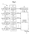
- the reference numeral 10 generally designates a diagram of a vehicle rollover detection system for implementing the methodology of the present invention.
- the methodology is carried out by an on-board microprocessor-based control unit such as a supplemental restraint controller that selectively activates various rollover restraint devices such as air bags, side curtains, seat belt pretensioners and pop-up roll bars.
- the inputs include the data developed by various sensors 12, 14, 16, 18, 20, and the output is a Deploy/No-Deploy (D/ND) command on line 22.
- the sensor data pertinent to rollover detection may include for example, vehicle speed, wheel speeds, roll rate, lateral acceleration, vertical acceleration, yaw rate, steering wheel position, tire pressure, and so on.
- the input data is subjected to conventional signal processing (low-pass filtering, for example) as indicated by the blocks 26, 28, 30, 32, 34 if not already processed, and made available for use by one or more event detection algorithms, as represented by the blocks 36, 38, 40, 42.
- Each block produces an event discrimination output (EDO-1, EDO-2, EDO-3, EDO-N), and the block 46 combines the outputs to produce the single deploy/no-deploy (D/ND) output on line 22.
- the algorithms represented by the blocks 36-42 are the same rollover detection algorithm, but differently calibrated.
- block 36 can represent a copy of the algorithm that is calibrated to reliably discriminate between rollover and non-rollover events associated with sudden braking and erratic movement of the vehicle steering wheel
- block 38 can represent a copy of the algorithm that is calibrated to reliably discriminate between rollover and non-rollover events associated with side impacts, and so on.
- This approach works best with an algorithm having a high degree of calibration flexibility; one example of such an algorithm in the field of rollover detection is the algorithm disclosed in the U.S. Patent No. 6,421,592, incorporated herein by reference.
- the algorithms represented by the blocks 36-42 can be different special-purpose algorithms, each designed to reliably distinguish between rollover events and non-rollover events associated with a specified kind of driver input or vehicle operating condition. For example, some algorithms are very good at discriminating rollover events associated with erratic driver steering inputs, while other algorithms are very good at discriminating rollover events associated with side impacts, and so on.
- FIGS. 2 and 3 illustrate two different ways the event discrimination outputs EDO-1 - EDO-N can be combined by the block 46.
- the simplest approach, illustrated in FIG. 2, is to logically combine the outputs using a Boolean-OR function as indicated by the block 50. If any of the event discrimination outputs EDO-1 - EDO-N indicates the presence of an impending rollover event, the OR block 50 produces a Deploy command on D/ND output line 22; otherwise the result is a No-Deploy command.
- FIG. 3 illustrates a somewhat different approach in which the outputs are arithmetically combined. The outputs are individually weighted by the blocks 52, 54, 56, 58 and summed by the block 60 to form a combined output on line 62.
- the combined output on line 62 is compared with a reference value REF by the comparator 64 to produce the D/ND output on line 22.
- the weights applied to each algorithm can be equal, they are preferably adjustable on-the-fly (by the control line 66, for example) based on an assessment of driver inputs and/or vehicle operating conditions so that higher weight can be accorded to an algorithm designed to detect rollover events associated with the current conditions.
- the block 68 has access to the input data from sensors 12-20 and carries out the function of assessing of driver inputs and/or vehicle operating conditions.
- the block 68 When a specified input or condition (such as a side impact) is detected, the block 68 signals the weight-setting block 70 to redistribute the weights applied by blocks 52-58 so that the output(s) of the algorithm(s) calibrated to discriminate rollover events associated with the detected condition is given more weight than algorithms calibrated to discriminate rollover events associated with different conditions.
- a specified input or condition such as a side impact
- FIG. 4 illustrates the performance of a rollover detection system configured according to the method of the present invention, as applied to six different data sets for rollover events A-F.
- the algorithm designated as CAL1 is calibrated to provide correct if not timely rollover discrimination for all of the events A-F.
- the algorithm designated as CAL2 is specifically calibrated to provide reliable detection of fast rollover events, due for example, to curb trips; and the algorithm designated as CAL3 is specifically calibrated to provide reliable detection of slow rollover events, due for example, to straying into a roadside ditch.
- a desired deployment time is specified for each of the events A-F, and the table of FIG.
- each of the algorithms correctly identifies the events A-F as rollover events, it is apparent that one or more of the algorithms are able to better discriminate any given event better than the other algorithms.
- the algorithm designated as CAL1 adequately discriminates rollover events B, D, E and F, but fails to adequately discriminate events A and C.
- the algorithm designated as CAL2 adequately discriminates rollover events B-F, but fails to adequately discriminate event A.
- the algorithm designated as CAL3 adequately discriminates rollover events A, B and E, but fails to adequately discriminate events C, D and F.
- the outputs are logically or arithmetically combined according to this invention, the output of the algorithm designated as CAL3 triggers a deployment command for events A and B; and the output of the algorithm designated as CAL2 triggers a deployment command for events C, D, E and F. If an additional set of rollover event data becomes available and the currently configured system fails to correctly discriminate the event, the only change required to achieve correct discrimination for all known events is to calibrate an additional version of the algorithm for the new event, and logically or arithmetically combine its output with the outputs of the existing versions of the algorithm.
- the system microprocessor can call the algorithm(s) as a function with different calibrations passed to it as an argument. For example, assume a system with sensors running at a 10ms sampling rate. Between samples, a main program executed by the microprocessor would pass the sensor data along with each set of calibrations to the algorithm(s), which would return a signal to the main program indicating whether or not to deploy. If at any time a deploy is returned, the main program would initiate the issue a deploy command. Otherwise, after 10ms the next set of sensor data would be received and the process would start over again.
- the only limitation on the number of calibrations would be the speed of the processor, since all of the sets need to be run in the 10ms interval between sensor data packets. Also, if functions defining the relationship between the variables for several calibrations of an algorithm can be found, the algorithm can change its own calibration during operation. For example, one variable can be varied over tens or hundreds of values and the other values calculated.
Landscapes
- Engineering & Computer Science (AREA)
- Physics & Mathematics (AREA)
- General Physics & Mathematics (AREA)
- Automation & Control Theory (AREA)
- Mathematical Physics (AREA)
- Evolutionary Computation (AREA)
- Artificial Intelligence (AREA)
- Algebra (AREA)
- Mathematical Analysis (AREA)
- Mathematical Optimization (AREA)
- Probability & Statistics with Applications (AREA)
- Pure & Applied Mathematics (AREA)
- Traffic Control Systems (AREA)
- Electrotherapy Devices (AREA)
Abstract
Description
- The present invention relates to event discrimination algorithms, and more particularly to a method of using multiple algorithms and/or calibration sets to achieve early event discrimination.
- Event discrimination algorithms are widely used to detect the occurrence of a specified condition or event that is not susceptible to direct measurement. For example, a restraint deployment algorithm in a motor vehicle is designed to detect the occurrence of a crash event severe enough to warrant deployment of passenger restraints based on measured acceleration data and the like, while discriminating against events that are not sufficiently severe to warrant deployment of the passenger restraints. Other automotive examples include algorithms for detecting an impending rollover event, and algorithms for discriminating between frontal impacts and side impacts.
- In general, event discrimination algorithms are developed by analyzing various sets of data measured during both events and non-events, and recognizing data patterns that can be used to discriminate between events and non-events. For example, the U.S. Patent No. 6,542,792 to Schubert et al. discloses a rollover detection algorithm in which an operating point of the vehicle defined by its roll rate and roll angle is compared with a calibrated threshold that divides the roll rate vs. roll angle space into rollover events and non-rollover events. While calibrating an algorithm to reliably discriminate a specified event for any one data set is not difficult, calibrating the algorithm to reliably discriminate a specified event for multiple data sets can be very difficult. For example, suppose input data sets for three deploy events A, B, C and three
non-deploy events - The present invention is directed to an improved method of using an event discrimination algorithms to distinguish between specified events and non-events, where multiple sets of the same or different algorithms are executed, and the results are logically or arithmetically combined to produce a single output that distinguishes between the specified events and non-events. In one embodiment, one given algorithm is repeatedly executed with different sets of calibration data; in another embodiment, a number of different algorithms are executed. In embodiments where the algorithm results are arithmetically combined, the weights accorded to each algorithm result are dynamically adjusted based on driver input or vehicle dynamic behavior data.
-
- FIG. 1 is a block diagram of an event discrimination system according to this invention;
- FIG. 2 is a block diagram illustrating a method of logically combining multiple event discrimination outputs according to this invention;
- FIG. 3 is a block diagram illustrating a method of arithmetically combining multiple event discrimination outputs according to this invention;
- FIG. 4 is a table depicting the operation of the invention in an embodiment where a single algorithm is executed with three different calibration sets.
- The method of the present invention is disclosed in the context of an event discrimination system designed to detect an impending rollover condition of a vehicle. However, it should be recognized that the method equally applies to other event discrimination systems, both automotive and non-automotive.
- Referring to the drawings, and particularly to Figure 1, the
reference numeral 10 generally designates a diagram of a vehicle rollover detection system for implementing the methodology of the present invention. The methodology is carried out by an on-board microprocessor-based control unit such as a supplemental restraint controller that selectively activates various rollover restraint devices such as air bags, side curtains, seat belt pretensioners and pop-up roll bars. The inputs include the data developed byvarious sensors line 22. The sensor data pertinent to rollover detection may include for example, vehicle speed, wheel speeds, roll rate, lateral acceleration, vertical acceleration, yaw rate, steering wheel position, tire pressure, and so on. The input data is subjected to conventional signal processing (low-pass filtering, for example) as indicated by theblocks blocks block 46 combines the outputs to produce the single deploy/no-deploy (D/ND) output online 22. - In a preferred implementation of the invention, the algorithms represented by the blocks 36-42 are the same rollover detection algorithm, but differently calibrated. For example,
block 36 can represent a copy of the algorithm that is calibrated to reliably discriminate between rollover and non-rollover events associated with sudden braking and erratic movement of the vehicle steering wheel,block 38 can represent a copy of the algorithm that is calibrated to reliably discriminate between rollover and non-rollover events associated with side impacts, and so on. This approach works best with an algorithm having a high degree of calibration flexibility; one example of such an algorithm in the field of rollover detection is the algorithm disclosed in the U.S. Patent No. 6,421,592, incorporated herein by reference. - Alternatively, the algorithms represented by the blocks 36-42 can be different special-purpose algorithms, each designed to reliably distinguish between rollover events and non-rollover events associated with a specified kind of driver input or vehicle operating condition. For example, some algorithms are very good at discriminating rollover events associated with erratic driver steering inputs, while other algorithms are very good at discriminating rollover events associated with side impacts, and so on.
- FIGS. 2 and 3 illustrate two different ways the event discrimination outputs EDO-1 - EDO-N can be combined by the
block 46. The simplest approach, illustrated in FIG. 2, is to logically combine the outputs using a Boolean-OR function as indicated by theblock 50. If any of the event discrimination outputs EDO-1 - EDO-N indicates the presence of an impending rollover event, theOR block 50 produces a Deploy command on D/ND output line 22; otherwise the result is a No-Deploy command. FIG. 3 illustrates a somewhat different approach in which the outputs are arithmetically combined. The outputs are individually weighted by theblocks block 60 to form a combined output online 62. The combined output online 62 is compared with a reference value REF by thecomparator 64 to produce the D/ND output online 22. While the weights applied to each algorithm can be equal, they are preferably adjustable on-the-fly (by thecontrol line 66, for example) based on an assessment of driver inputs and/or vehicle operating conditions so that higher weight can be accorded to an algorithm designed to detect rollover events associated with the current conditions. In the diagram of FIG. 1, theblock 68 has access to the input data from sensors 12-20 and carries out the function of assessing of driver inputs and/or vehicle operating conditions. When a specified input or condition (such as a side impact) is detected, theblock 68 signals the weight-setting block 70 to redistribute the weights applied by blocks 52-58 so that the output(s) of the algorithm(s) calibrated to discriminate rollover events associated with the detected condition is given more weight than algorithms calibrated to discriminate rollover events associated with different conditions. - FIG. 4 illustrates the performance of a rollover detection system configured according to the method of the present invention, as applied to six different data sets for rollover events A-F. In the illustration, three different copies of the same highly flexible rollover detection algorithm are individually calibrated and separately executed for each event A-F. The algorithm designated as CAL1 is calibrated to provide correct if not timely rollover discrimination for all of the events A-F. The algorithm designated as CAL2 is specifically calibrated to provide reliable detection of fast rollover events, due for example, to curb trips; and the algorithm designated as CAL3 is specifically calibrated to provide reliable detection of slow rollover events, due for example, to straying into a roadside ditch. A desired deployment time is specified for each of the events A-F, and the table of FIG. 4 indicates the lateness of the deploy command relative to the desired time; a positive number indicates a deployment command that is late (which is undesirable), while a negative number indicates a deployment command that is early (which is desirable). While each of the algorithms correctly identifies the events A-F as rollover events, it is apparent that one or more of the algorithms are able to better discriminate any given event better than the other algorithms. For example, the algorithm designated as CAL1 adequately discriminates rollover events B, D, E and F, but fails to adequately discriminate events A and C. The algorithm designated as CAL2 adequately discriminates rollover events B-F, but fails to adequately discriminate event A. And the algorithm designated as CAL3 adequately discriminates rollover events A, B and E, but fails to adequately discriminate events C, D and F. While no single calibration of the algorithm can timely discriminate all of the rollover events, at least one version of the algorithm can timely discriminate any given event. When the outputs are logically or arithmetically combined according to this invention, the output of the algorithm designated as CAL3 triggers a deployment command for events A and B; and the output of the algorithm designated as CAL2 triggers a deployment command for events C, D, E and F. If an additional set of rollover event data becomes available and the currently configured system fails to correctly discriminate the event, the only change required to achieve correct discrimination for all known events is to calibrate an additional version of the algorithm for the new event, and logically or arithmetically combine its output with the outputs of the existing versions of the algorithm. Of course, this same advantage occurs in embodiments comprising a number of different algorithms instead of different versions of the same algorithm. Since each of the algorithms is designed to detect a certain class of rollover events while discriminating against all non-rollover events in general, the logical or arithmetic combination of all algorithm outputs will also identify all rollover events while discriminating against all non-rollover events.
- The number of algorithm versions or different algorithms that can be executed according to this invention on any given system depends only on the memory and throughput capabilities of the system. In practice, the system microprocessor can call the algorithm(s) as a function with different calibrations passed to it as an argument. For example, assume a system with sensors running at a 10ms sampling rate. Between samples, a main program executed by the microprocessor would pass the sensor data along with each set of calibrations to the algorithm(s), which would return a signal to the main program indicating whether or not to deploy. If at any time a deploy is returned, the main program would initiate the issue a deploy command. Otherwise, after 10ms the next set of sensor data would be received and the process would start over again. The only limitation on the number of calibrations would be the speed of the processor, since all of the sets need to be run in the 10ms interval between sensor data packets. Also, if functions defining the relationship between the variables for several calibrations of an algorithm can be found, the algorithm can change its own calibration during operation. For example, one variable can be varied over tens or hundreds of values and the other values calculated.
- While the method of the present invention has been described with respect to the illustrated embodiment, it is recognized that numerous modifications and variations in addition to those mentioned herein will occur to those skilled in the art. Accordingly, it is intended that the invention not be limited to the disclosed embodiment, but that it have the full scope permitted by the language of the following claims.
Claims (10)
- A method of discriminating an occurrence of a specified event in a system based on measured or estimated system parameter data pertinent to said event, the method comprising the steps of:executing a number of event discrimination algorithms individually calibrated to detect different patterns of parameter data that are characteristic of the occurrence of said specified event, each algorithm producing an event discrimination output (36-42); andcombining the event discrimination outputs produced by each of said algorithms to form a single output that discriminates the occurrence of said specified event (46).
- The method of claim 1, including the steps of:developing a plurality of different calibrations for a single event discrimination algorithm for detecting said different patterns of parameter data that are characteristic of the occurrence of said specified event (36-42); andexecuting said single event discrimination algorithm repeatedly with said different calibrations to produce said event discrimination outputs that are combined to form said single output (46).
- The method of claim 1, wherein the step of combining said event discrimination outputs includes the step of:combining said event discrimination outputs with a logical-OR function (50).
- The method of claim 1, wherein the step of combining said event discrimination outputs includes the steps of:applying calibrated weights to each of said event discrimination outputs (52-58);combining the weighted event discrimination outputs to form a combined output (60); andforming said single output based on said combined output (64, 22).
- The method of claim 1, wherein said different patterns of parameter data are characteristic of occurrences of said specified event due to different dynamic conditions of said system.
- The method of claim 5, including the steps of:monitoring system data to detect at least one of said different dynamic conditions of said system (68);identifying one or more of the event discrimination algorithms that are calibrated to detect a pattern of parameter data that is characteristic of occurrences of said specified event due to the detected dynamic condition (70); andaccording higher weight to the event discrimination output of the identified event discrimination algorithm when combining the event discrimination outputs produced by said algorithms (46).
- The method of claim 6, including the steps of:storing a set of calibrated weights to be applied to each of said event discrimination outputs for arithmetically combining said event discrimination outputs (46); andadjusting said calibrated weights in response to detection of said at least one the different dynamic condition of said system so as to increase the weight applied to the event discrimination output of the identified event discrimination algorithm (70).
- The method of claim 1, wherein the specified event is a rollover of a vehicle operated by a driver, and said different patterns of parameter data are characteristic of occurrences of said specified event due to different actions of said driver (68).
- The method of claim 8, including the steps of:monitoring system data to detect at least one of said different actions of said driver (68);identifying one or more of the event discrimination algorithms that are calibrated to detect a pattern of parameter data that is characteristic of occurrences of said specified event due to the at least one detected action of the driver (70); andaccording higher weight to the event discrimination output of the identified event discrimination algorithm when combining the event discrimination outputs produced by said algorithms (46).
- The method of claim 9, including the steps of:storing a set of calibrated weights to be applied to each of said event discrimination outputs for arithmetically combining said event discrimination outputs (46); andadjusting said calibrated weights in response to detection of said at least one action of said driver so as to increase the weight applied to the event discrimination output of the identified event discrimination algorithm (70).
Applications Claiming Priority (1)
| Application Number | Priority Date | Filing Date | Title |
|---|---|---|---|
| US10/921,722 US7269483B2 (en) | 2004-08-19 | 2004-08-19 | Multiple algorithm event discrimination method |
Publications (3)
| Publication Number | Publication Date |
|---|---|
| EP1628180A2 true EP1628180A2 (en) | 2006-02-22 |
| EP1628180A3 EP1628180A3 (en) | 2006-05-31 |
| EP1628180B1 EP1628180B1 (en) | 2008-11-12 |
Family
ID=35445871
Family Applications (1)
| Application Number | Title | Priority Date | Filing Date |
|---|---|---|---|
| EP05076729A Expired - Lifetime EP1628180B1 (en) | 2004-08-19 | 2005-07-27 | Multiple algorithm event discrimination method |
Country Status (4)
| Country | Link |
|---|---|
| US (1) | US7269483B2 (en) |
| EP (1) | EP1628180B1 (en) |
| AT (1) | ATE414295T1 (en) |
| DE (1) | DE602005010946D1 (en) |
Cited By (3)
| Publication number | Priority date | Publication date | Assignee | Title |
|---|---|---|---|---|
| EP1552987A3 (en) * | 2004-01-08 | 2006-06-21 | Delphi Technologies, Inc. | Reconfigurable method for event detection in a motor vehicle |
| EP1403146A3 (en) * | 2002-09-25 | 2006-06-28 | Yazaki Corporation | Method of assisting design of a wiring structure, its apparatus and its program |
| WO2017102130A1 (en) * | 2015-12-15 | 2017-06-22 | Robert Bosch Gmbh | Acceleration sensing of fast roll and slow roll for vehicle |
Families Citing this family (24)
| Publication number | Priority date | Publication date | Assignee | Title |
|---|---|---|---|---|
| DE10235567A1 (en) * | 2002-08-03 | 2004-02-19 | Robert Bosch Gmbh | Motor vehicle rolling over detection device for activation of safety restraining systems, has sensors and a processor for detecting rolling over about both transverse and horizontal axes |
| EP1619083B1 (en) * | 2004-07-19 | 2008-04-23 | Delphi Technologies, Inc. | A method and system for detecting vehicle rollover events |
| US7873449B2 (en) * | 2007-03-29 | 2011-01-18 | Ford Global Technologies | Vehicle safety system with advanced tire monitoring |
| US8032281B2 (en) * | 2007-03-29 | 2011-10-04 | Ford Global Technologies | Vehicle control system with advanced tire monitoring |
| US7778741B2 (en) * | 2007-03-29 | 2010-08-17 | Ford Global Technologies | Vehicle stability control system with tire monitoring |
| US7996132B2 (en) * | 2007-11-29 | 2011-08-09 | Robert Bosch Gmbh | Fast sensing system and method for soil- and curb-tripped vehicle rollovers |
| US9717896B2 (en) | 2007-12-18 | 2017-08-01 | Gearbox, Llc | Treatment indications informed by a priori implant information |
| US20090287120A1 (en) | 2007-12-18 | 2009-11-19 | Searete Llc, A Limited Liability Corporation Of The State Of Delaware | Circulatory monitoring systems and methods |
| US8636670B2 (en) | 2008-05-13 | 2014-01-28 | The Invention Science Fund I, Llc | Circulatory monitoring systems and methods |
| JP2010040994A (en) * | 2008-08-08 | 2010-02-18 | Toshiba Corp | Semiconductor memory device, and method of manufacturing the same |
| US8275516B2 (en) | 2009-07-21 | 2012-09-25 | Trimble Navigation Limited | Agricultural vehicle autopilot rollover risk assessment system |
| US8346439B2 (en) * | 2009-09-24 | 2013-01-01 | Continental Teves, Inc. | Safety method and device for vehicle rollover prediction using estimated lateral vehicle velocity |
| US9406222B2 (en) | 2012-10-18 | 2016-08-02 | Calamp Corp. | Systems and methods for location reporting of detected events in vehicle operation |
| US10107831B2 (en) | 2012-11-21 | 2018-10-23 | Calamp Corp | Systems and methods for efficient characterization of acceleration events |
| US10466269B2 (en) | 2013-02-19 | 2019-11-05 | Calamp Corp. | Systems and methods for low latency 3-axis accelerometer calibration |
| US9644977B2 (en) | 2015-05-22 | 2017-05-09 | Calamp Corp. | Systems and methods for determining vehicle operational status |
| US10214166B2 (en) | 2015-06-11 | 2019-02-26 | Calamp Corp. | Systems and methods for impact detection with noise attenuation of a sensor signal |
| US10055909B2 (en) | 2016-07-08 | 2018-08-21 | Calamp Corp. | Systems and methods for crash determination |
| US10395438B2 (en) | 2016-08-19 | 2019-08-27 | Calamp Corp. | Systems and methods for crash determination with noise filtering |
| US10219117B2 (en) | 2016-10-12 | 2019-02-26 | Calamp Corp. | Systems and methods for radio access interfaces |
| US10473750B2 (en) | 2016-12-08 | 2019-11-12 | Calamp Corp. | Systems and methods for tracking multiple collocated assets |
| US10599421B2 (en) | 2017-07-14 | 2020-03-24 | Calamp Corp. | Systems and methods for failsafe firmware upgrades |
| US20190141156A1 (en) | 2017-11-06 | 2019-05-09 | Calamp Corp. | Systems and Methods for Dynamic Telematics Messaging |
| US11206171B2 (en) | 2017-11-07 | 2021-12-21 | Calamp Corp. | Systems and methods for dynamic device programming |
Citations (2)
| Publication number | Priority date | Publication date | Assignee | Title |
|---|---|---|---|---|
| US6421592B1 (en) | 1998-03-17 | 2002-07-16 | Autoliv Development Ab | Safety arrangement in a vehicle |
| US6542792B2 (en) | 2000-11-29 | 2003-04-01 | Delphi Technologies, Inc. | Vehicle rollover detection apparatus and method |
Family Cites Families (11)
| Publication number | Priority date | Publication date | Assignee | Title |
|---|---|---|---|---|
| US5262949A (en) * | 1990-02-20 | 1993-11-16 | Zexel Corporation | Control system for vehicle safety device |
| US7284769B2 (en) * | 1995-06-07 | 2007-10-23 | Automotive Technologies International, Inc. | Method and apparatus for sensing a vehicle crash |
| US5550751A (en) | 1993-10-15 | 1996-08-27 | The Texas A & M University System | Expert system for detecting high impedance faults |
| US5583771A (en) * | 1994-08-04 | 1996-12-10 | Delco Electronics Corp. | Method and apparatus for distinguishing between deployment events and non-deployment events in an SIR system |
| US7085637B2 (en) * | 1997-10-22 | 2006-08-01 | Intelligent Technologies International, Inc. | Method and system for controlling a vehicle |
| US6186539B1 (en) * | 1998-07-01 | 2001-02-13 | Trw Inc. | Method and apparatus for controlling an actuatable restraint device using crash severity indexing and crush zone sensor |
| US6584388B2 (en) | 2001-11-08 | 2003-06-24 | Delphi Technologies, Inc. | Adaptive rollover detection apparatus and method |
| US6529811B2 (en) * | 2001-03-01 | 2003-03-04 | Automotive Systems Laboratory, Inc. | Vehicle rollover detection system |
| DE10330539B4 (en) * | 2002-07-22 | 2008-08-14 | Siemens Vdo Automotive Corp., Auburn Hills | A crash event detection system and method of operating such a system |
| US7206679B2 (en) | 2004-01-08 | 2007-04-17 | Delphi Technologies, Inc. | Reconfigurable methodology for event detection in a motor vehicle |
| US7308350B2 (en) * | 2004-05-20 | 2007-12-11 | Ford Global Technologies, Llc | Method and apparatus for determining adaptive brake gain parameters for use in a safety system of an automotive vehicle |
-
2004
- 2004-08-19 US US10/921,722 patent/US7269483B2/en not_active Expired - Lifetime
-
2005
- 2005-07-27 DE DE602005010946T patent/DE602005010946D1/en not_active Expired - Lifetime
- 2005-07-27 EP EP05076729A patent/EP1628180B1/en not_active Expired - Lifetime
- 2005-07-27 AT AT05076729T patent/ATE414295T1/en not_active IP Right Cessation
Patent Citations (2)
| Publication number | Priority date | Publication date | Assignee | Title |
|---|---|---|---|---|
| US6421592B1 (en) | 1998-03-17 | 2002-07-16 | Autoliv Development Ab | Safety arrangement in a vehicle |
| US6542792B2 (en) | 2000-11-29 | 2003-04-01 | Delphi Technologies, Inc. | Vehicle rollover detection apparatus and method |
Cited By (5)
| Publication number | Priority date | Publication date | Assignee | Title |
|---|---|---|---|---|
| EP1403146A3 (en) * | 2002-09-25 | 2006-06-28 | Yazaki Corporation | Method of assisting design of a wiring structure, its apparatus and its program |
| EP1552987A3 (en) * | 2004-01-08 | 2006-06-21 | Delphi Technologies, Inc. | Reconfigurable method for event detection in a motor vehicle |
| US7206679B2 (en) | 2004-01-08 | 2007-04-17 | Delphi Technologies, Inc. | Reconfigurable methodology for event detection in a motor vehicle |
| WO2017102130A1 (en) * | 2015-12-15 | 2017-06-22 | Robert Bosch Gmbh | Acceleration sensing of fast roll and slow roll for vehicle |
| US9821744B2 (en) | 2015-12-15 | 2017-11-21 | Robert Bosch Gmbh | Acceleration sensing of fast roll and slow roll for vehicle |
Also Published As
| Publication number | Publication date |
|---|---|
| US7269483B2 (en) | 2007-09-11 |
| ATE414295T1 (en) | 2008-11-15 |
| US20060041336A1 (en) | 2006-02-23 |
| DE602005010946D1 (en) | 2008-12-24 |
| EP1628180B1 (en) | 2008-11-12 |
| EP1628180A3 (en) | 2006-05-31 |
Similar Documents
| Publication | Publication Date | Title |
|---|---|---|
| EP1628180B1 (en) | Multiple algorithm event discrimination method | |
| US7292921B2 (en) | Method for activating restraining means | |
| KR101805672B1 (en) | Method and apparatus for controlling an actuatable restraining device using multi-region enchanced discrimination | |
| KR100725735B1 (en) | Vehicle passenger restraint system with distributed sensors | |
| KR100631268B1 (en) | Variable time venting algorithm | |
| CN102259627B (en) | Method and apparatus for detecting pedestrian vehicle impact | |
| US20100305818A1 (en) | Method and control unit for activating occupant protection means, as well as computer program and computer program product | |
| WO1999020491A1 (en) | Crash detection system | |
| US20040015324A1 (en) | Crash detection system including roll-over discrimination | |
| US20100168965A1 (en) | Method and control device for triggering passenger protection means | |
| US11541833B2 (en) | Apparatus and method to detect crash type of vehicle | |
| US7349783B2 (en) | Supplemental restraint deployment method with anticipatory crash classification | |
| KR102272076B1 (en) | Airbag deployment method in accordance with Small overlap collision | |
| US7424354B2 (en) | Supplemental restraint deployment method using dynamic crash classification | |
| US6157881A (en) | Supplemental restraint rear impact deployment control method | |
| KR102928633B1 (en) | Air bag deployment apparatus and method | |
| KR20060033824A (en) | Air-bag's control method | |
| KR101028368B1 (en) | Airbag Control Device and Method | |
| KR20190044817A (en) | Apparatus and method for controlling unfolding of airbag | |
| JP2001242043A (en) | Resonance prediction device and resonance prediction method | |
| KR20060033825A (en) | Air bag control method |
Legal Events
| Date | Code | Title | Description |
|---|---|---|---|
| PUAI | Public reference made under article 153(3) epc to a published international application that has entered the european phase |
Free format text: ORIGINAL CODE: 0009012 |
|
| AK | Designated contracting states |
Kind code of ref document: A2 Designated state(s): AT BE BG CH CY CZ DE DK EE ES FI FR GB GR HU IE IS IT LI LT LU LV MC NL PL PT RO SE SI SK TR |
|
| AX | Request for extension of the european patent |
Extension state: AL BA HR MK YU |
|
| PUAL | Search report despatched |
Free format text: ORIGINAL CODE: 0009013 |
|
| AK | Designated contracting states |
Kind code of ref document: A3 Designated state(s): AT BE BG CH CY CZ DE DK EE ES FI FR GB GR HU IE IS IT LI LT LU LV MC NL PL PT RO SE SI SK TR |
|
| AX | Request for extension of the european patent |
Extension state: AL BA HR MK YU |
|
| 17P | Request for examination filed |
Effective date: 20061130 |
|
| AKX | Designation fees paid |
Designated state(s): AT BE BG CH CY CZ DE DK EE ES FI FR GB GR HU IE IS IT LI LT LU LV MC NL PL PT RO SE SI SK TR |
|
| R17C | First examination report despatched (corrected) |
Effective date: 20070112 |
|
| R17C | First examination report despatched (corrected) |
Effective date: 20070809 |
|
| GRAP | Despatch of communication of intention to grant a patent |
Free format text: ORIGINAL CODE: EPIDOSNIGR1 |
|
| GRAS | Grant fee paid |
Free format text: ORIGINAL CODE: EPIDOSNIGR3 |
|
| GRAA | (expected) grant |
Free format text: ORIGINAL CODE: 0009210 |
|
| AK | Designated contracting states |
Kind code of ref document: B1 Designated state(s): AT BE BG CH CY CZ DE DK EE ES FI FR GB GR HU IE IS IT LI LT LU LV MC NL PL PT RO SE SI SK TR |
|
| REG | Reference to a national code |
Ref country code: GB Ref legal event code: FG4D |
|
| REG | Reference to a national code |
Ref country code: CH Ref legal event code: EP |
|
| REG | Reference to a national code |
Ref country code: IE Ref legal event code: FG4D |
|
| REF | Corresponds to: |
Ref document number: 602005010946 Country of ref document: DE Date of ref document: 20081224 Kind code of ref document: P |
|
| LTIE | Lt: invalidation of european patent or patent extension |
Effective date: 20081112 |
|
| PG25 | Lapsed in a contracting state [announced via postgrant information from national office to epo] |
Ref country code: ES Free format text: LAPSE BECAUSE OF FAILURE TO SUBMIT A TRANSLATION OF THE DESCRIPTION OR TO PAY THE FEE WITHIN THE PRESCRIBED TIME-LIMIT Effective date: 20090223 Ref country code: AT Free format text: LAPSE BECAUSE OF FAILURE TO SUBMIT A TRANSLATION OF THE DESCRIPTION OR TO PAY THE FEE WITHIN THE PRESCRIBED TIME-LIMIT Effective date: 20081112 Ref country code: LT Free format text: LAPSE BECAUSE OF FAILURE TO SUBMIT A TRANSLATION OF THE DESCRIPTION OR TO PAY THE FEE WITHIN THE PRESCRIBED TIME-LIMIT Effective date: 20081112 |
|
| NLV1 | Nl: lapsed or annulled due to failure to fulfill the requirements of art. 29p and 29m of the patents act | ||
| PG25 | Lapsed in a contracting state [announced via postgrant information from national office to epo] |
Ref country code: FI Free format text: LAPSE BECAUSE OF FAILURE TO SUBMIT A TRANSLATION OF THE DESCRIPTION OR TO PAY THE FEE WITHIN THE PRESCRIBED TIME-LIMIT Effective date: 20081112 Ref country code: LV Free format text: LAPSE BECAUSE OF FAILURE TO SUBMIT A TRANSLATION OF THE DESCRIPTION OR TO PAY THE FEE WITHIN THE PRESCRIBED TIME-LIMIT Effective date: 20081112 Ref country code: SI Free format text: LAPSE BECAUSE OF FAILURE TO SUBMIT A TRANSLATION OF THE DESCRIPTION OR TO PAY THE FEE WITHIN THE PRESCRIBED TIME-LIMIT Effective date: 20081112 Ref country code: NL Free format text: LAPSE BECAUSE OF FAILURE TO SUBMIT A TRANSLATION OF THE DESCRIPTION OR TO PAY THE FEE WITHIN THE PRESCRIBED TIME-LIMIT Effective date: 20081112 Ref country code: PL Free format text: LAPSE BECAUSE OF FAILURE TO SUBMIT A TRANSLATION OF THE DESCRIPTION OR TO PAY THE FEE WITHIN THE PRESCRIBED TIME-LIMIT Effective date: 20081112 Ref country code: IS Free format text: LAPSE BECAUSE OF FAILURE TO SUBMIT A TRANSLATION OF THE DESCRIPTION OR TO PAY THE FEE WITHIN THE PRESCRIBED TIME-LIMIT Effective date: 20090312 |
|
| PG25 | Lapsed in a contracting state [announced via postgrant information from national office to epo] |
Ref country code: DK Free format text: LAPSE BECAUSE OF FAILURE TO SUBMIT A TRANSLATION OF THE DESCRIPTION OR TO PAY THE FEE WITHIN THE PRESCRIBED TIME-LIMIT Effective date: 20081112 Ref country code: BE Free format text: LAPSE BECAUSE OF FAILURE TO SUBMIT A TRANSLATION OF THE DESCRIPTION OR TO PAY THE FEE WITHIN THE PRESCRIBED TIME-LIMIT Effective date: 20081112 Ref country code: EE Free format text: LAPSE BECAUSE OF FAILURE TO SUBMIT A TRANSLATION OF THE DESCRIPTION OR TO PAY THE FEE WITHIN THE PRESCRIBED TIME-LIMIT Effective date: 20081112 Ref country code: RO Free format text: LAPSE BECAUSE OF FAILURE TO SUBMIT A TRANSLATION OF THE DESCRIPTION OR TO PAY THE FEE WITHIN THE PRESCRIBED TIME-LIMIT Effective date: 20081112 Ref country code: BG Free format text: LAPSE BECAUSE OF FAILURE TO SUBMIT A TRANSLATION OF THE DESCRIPTION OR TO PAY THE FEE WITHIN THE PRESCRIBED TIME-LIMIT Effective date: 20090212 |
|
| PG25 | Lapsed in a contracting state [announced via postgrant information from national office to epo] |
Ref country code: PT Free format text: LAPSE BECAUSE OF FAILURE TO SUBMIT A TRANSLATION OF THE DESCRIPTION OR TO PAY THE FEE WITHIN THE PRESCRIBED TIME-LIMIT Effective date: 20090413 Ref country code: CZ Free format text: LAPSE BECAUSE OF FAILURE TO SUBMIT A TRANSLATION OF THE DESCRIPTION OR TO PAY THE FEE WITHIN THE PRESCRIBED TIME-LIMIT Effective date: 20081112 Ref country code: SE Free format text: LAPSE BECAUSE OF FAILURE TO SUBMIT A TRANSLATION OF THE DESCRIPTION OR TO PAY THE FEE WITHIN THE PRESCRIBED TIME-LIMIT Effective date: 20090212 |
|
| PLBE | No opposition filed within time limit |
Free format text: ORIGINAL CODE: 0009261 |
|
| STAA | Information on the status of an ep patent application or granted ep patent |
Free format text: STATUS: NO OPPOSITION FILED WITHIN TIME LIMIT |
|
| PG25 | Lapsed in a contracting state [announced via postgrant information from national office to epo] |
Ref country code: SK Free format text: LAPSE BECAUSE OF FAILURE TO SUBMIT A TRANSLATION OF THE DESCRIPTION OR TO PAY THE FEE WITHIN THE PRESCRIBED TIME-LIMIT Effective date: 20081112 |
|
| 26N | No opposition filed |
Effective date: 20090813 |
|
| PG25 | Lapsed in a contracting state [announced via postgrant information from national office to epo] |
Ref country code: MC Free format text: LAPSE BECAUSE OF NON-PAYMENT OF DUE FEES Effective date: 20090731 |
|
| REG | Reference to a national code |
Ref country code: CH Ref legal event code: PL |
|
| PG25 | Lapsed in a contracting state [announced via postgrant information from national office to epo] |
Ref country code: CH Free format text: LAPSE BECAUSE OF NON-PAYMENT OF DUE FEES Effective date: 20090731 Ref country code: LI Free format text: LAPSE BECAUSE OF NON-PAYMENT OF DUE FEES Effective date: 20090731 |
|
| PG25 | Lapsed in a contracting state [announced via postgrant information from national office to epo] |
Ref country code: IE Free format text: LAPSE BECAUSE OF NON-PAYMENT OF DUE FEES Effective date: 20090727 |
|
| PG25 | Lapsed in a contracting state [announced via postgrant information from national office to epo] |
Ref country code: GR Free format text: LAPSE BECAUSE OF FAILURE TO SUBMIT A TRANSLATION OF THE DESCRIPTION OR TO PAY THE FEE WITHIN THE PRESCRIBED TIME-LIMIT Effective date: 20090213 |
|
| PG25 | Lapsed in a contracting state [announced via postgrant information from national office to epo] |
Ref country code: IT Free format text: LAPSE BECAUSE OF FAILURE TO SUBMIT A TRANSLATION OF THE DESCRIPTION OR TO PAY THE FEE WITHIN THE PRESCRIBED TIME-LIMIT Effective date: 20081112 |
|
| PG25 | Lapsed in a contracting state [announced via postgrant information from national office to epo] |
Ref country code: LU Free format text: LAPSE BECAUSE OF NON-PAYMENT OF DUE FEES Effective date: 20090727 |
|
| PG25 | Lapsed in a contracting state [announced via postgrant information from national office to epo] |
Ref country code: HU Free format text: LAPSE BECAUSE OF FAILURE TO SUBMIT A TRANSLATION OF THE DESCRIPTION OR TO PAY THE FEE WITHIN THE PRESCRIBED TIME-LIMIT Effective date: 20090513 |
|
| PG25 | Lapsed in a contracting state [announced via postgrant information from national office to epo] |
Ref country code: TR Free format text: LAPSE BECAUSE OF FAILURE TO SUBMIT A TRANSLATION OF THE DESCRIPTION OR TO PAY THE FEE WITHIN THE PRESCRIBED TIME-LIMIT Effective date: 20081112 |
|
| PG25 | Lapsed in a contracting state [announced via postgrant information from national office to epo] |
Ref country code: CY Free format text: LAPSE BECAUSE OF FAILURE TO SUBMIT A TRANSLATION OF THE DESCRIPTION OR TO PAY THE FEE WITHIN THE PRESCRIBED TIME-LIMIT Effective date: 20081112 |
|
| REG | Reference to a national code |
Ref country code: FR Ref legal event code: PLFP Year of fee payment: 12 |
|
| REG | Reference to a national code |
Ref country code: FR Ref legal event code: PLFP Year of fee payment: 13 |
|
| REG | Reference to a national code |
Ref country code: FR Ref legal event code: PLFP Year of fee payment: 14 |
|
| REG | Reference to a national code |
Ref country code: DE Ref legal event code: R082 Ref document number: 602005010946 Country of ref document: DE Representative=s name: MANITZ FINSTERWALD PATENT- UND RECHTSANWALTSPA, DE Ref country code: DE Ref legal event code: R082 Ref document number: 602005010946 Country of ref document: DE Representative=s name: MANITZ FINSTERWALD PATENTANWAELTE PARTMBB, DE Ref country code: DE Ref legal event code: R081 Ref document number: 602005010946 Country of ref document: DE Owner name: APTIV TECHNOLOGIES LIMITED, BB Free format text: FORMER OWNER: DELPHI TECHNOLOGIES, INC., TROY, MICH., US |
|
| REG | Reference to a national code |
Ref country code: GB Ref legal event code: 732E Free format text: REGISTERED BETWEEN 20190117 AND 20190123 |
|
| REG | Reference to a national code |
Ref country code: GB Ref legal event code: 732E Free format text: REGISTERED BETWEEN 20190124 AND 20190130 |
|
| PGFP | Annual fee paid to national office [announced via postgrant information from national office to epo] |
Ref country code: FR Payment date: 20190726 Year of fee payment: 15 |
|
| PGFP | Annual fee paid to national office [announced via postgrant information from national office to epo] |
Ref country code: GB Payment date: 20190729 Year of fee payment: 15 |
|
| GBPC | Gb: european patent ceased through non-payment of renewal fee |
Effective date: 20200727 |
|
| PG25 | Lapsed in a contracting state [announced via postgrant information from national office to epo] |
Ref country code: GB Free format text: LAPSE BECAUSE OF NON-PAYMENT OF DUE FEES Effective date: 20200727 Ref country code: FR Free format text: LAPSE BECAUSE OF NON-PAYMENT OF DUE FEES Effective date: 20200731 |
|
| P01 | Opt-out of the competence of the unified patent court (upc) registered |
Effective date: 20230425 |
|
| PGFP | Annual fee paid to national office [announced via postgrant information from national office to epo] |
Ref country code: DE Payment date: 20240723 Year of fee payment: 20 |
|
| REG | Reference to a national code |
Ref country code: DE Ref legal event code: R081 Ref document number: 602005010946 Country of ref document: DE Owner name: APTIV TECHNOLOGIES AG, CH Free format text: FORMER OWNER: APTIV TECHNOLOGIES LIMITED, ST. MICHAEL, BB |
|
| REG | Reference to a national code |
Ref country code: DE Ref legal event code: R071 Ref document number: 602005010946 Country of ref document: DE |