EP1628103A2 - Electricity generating and air conditioning system with dehumidifier - Google Patents
Electricity generating and air conditioning system with dehumidifier Download PDFInfo
- Publication number
- EP1628103A2 EP1628103A2 EP05001454A EP05001454A EP1628103A2 EP 1628103 A2 EP1628103 A2 EP 1628103A2 EP 05001454 A EP05001454 A EP 05001454A EP 05001454 A EP05001454 A EP 05001454A EP 1628103 A2 EP1628103 A2 EP 1628103A2
- Authority
- EP
- European Patent Office
- Prior art keywords
- heat
- heat exchanger
- engine
- heater
- cooling water
- Prior art date
- Legal status (The legal status is an assumption and is not a legal conclusion. Google has not performed a legal analysis and makes no representation as to the accuracy of the status listed.)
- Withdrawn
Links
- 230000005611 electricity Effects 0.000 title claims abstract description 78
- 238000004378 air conditioning Methods 0.000 title claims abstract description 61
- 230000008929 regeneration Effects 0.000 claims abstract description 92
- 238000011069 regeneration method Methods 0.000 claims abstract description 92
- 239000002918 waste heat Substances 0.000 claims abstract description 32
- 239000000498 cooling water Substances 0.000 claims description 65
- 239000007789 gas Substances 0.000 claims description 60
- 239000003795 chemical substances by application Substances 0.000 claims description 41
- 238000001816 cooling Methods 0.000 claims description 30
- 238000010438 heat treatment Methods 0.000 claims description 30
- 239000003507 refrigerant Substances 0.000 description 24
- 238000010586 diagram Methods 0.000 description 16
- 230000008901 benefit Effects 0.000 description 7
- 239000000446 fuel Substances 0.000 description 6
- 238000002485 combustion reaction Methods 0.000 description 3
- 239000000470 constituent Substances 0.000 description 3
- 230000004888 barrier function Effects 0.000 description 2
- 238000011144 upstream manufacturing Methods 0.000 description 2
- 238000007792 addition Methods 0.000 description 1
- 230000000694 effects Effects 0.000 description 1
- 230000006872 improvement Effects 0.000 description 1
- 239000003915 liquefied petroleum gas Substances 0.000 description 1
- 230000004048 modification Effects 0.000 description 1
- 238000012986 modification Methods 0.000 description 1
- 238000006467 substitution reaction Methods 0.000 description 1
Images




Classifications
-
- F—MECHANICAL ENGINEERING; LIGHTING; HEATING; WEAPONS; BLASTING
- F25—REFRIGERATION OR COOLING; COMBINED HEATING AND REFRIGERATION SYSTEMS; HEAT PUMP SYSTEMS; MANUFACTURE OR STORAGE OF ICE; LIQUEFACTION SOLIDIFICATION OF GASES
- F25B—REFRIGERATION MACHINES, PLANTS OR SYSTEMS; COMBINED HEATING AND REFRIGERATION SYSTEMS; HEAT PUMP SYSTEMS
- F25B27/00—Machines, plants or systems, using particular sources of energy
- F25B27/02—Machines, plants or systems, using particular sources of energy using waste heat, e.g. from internal-combustion engines
-
- F—MECHANICAL ENGINEERING; LIGHTING; HEATING; WEAPONS; BLASTING
- F25—REFRIGERATION OR COOLING; COMBINED HEATING AND REFRIGERATION SYSTEMS; HEAT PUMP SYSTEMS; MANUFACTURE OR STORAGE OF ICE; LIQUEFACTION SOLIDIFICATION OF GASES
- F25B—REFRIGERATION MACHINES, PLANTS OR SYSTEMS; COMBINED HEATING AND REFRIGERATION SYSTEMS; HEAT PUMP SYSTEMS
- F25B30/00—Heat pumps
-
- F—MECHANICAL ENGINEERING; LIGHTING; HEATING; WEAPONS; BLASTING
- F24—HEATING; RANGES; VENTILATING
- F24F—AIR-CONDITIONING; AIR-HUMIDIFICATION; VENTILATION; USE OF AIR CURRENTS FOR SCREENING
- F24F1/00—Room units for air-conditioning, e.g. separate or self-contained units or units receiving primary air from a central station
-
- F—MECHANICAL ENGINEERING; LIGHTING; HEATING; WEAPONS; BLASTING
- F24—HEATING; RANGES; VENTILATING
- F24F—AIR-CONDITIONING; AIR-HUMIDIFICATION; VENTILATION; USE OF AIR CURRENTS FOR SCREENING
- F24F3/00—Air-conditioning systems in which conditioned primary air is supplied from one or more central stations to distributing units in the rooms or spaces where it may receive secondary treatment; Apparatus specially designed for such systems
- F24F3/12—Air-conditioning systems in which conditioned primary air is supplied from one or more central stations to distributing units in the rooms or spaces where it may receive secondary treatment; Apparatus specially designed for such systems characterised by the treatment of the air otherwise than by heating and cooling
- F24F3/14—Air-conditioning systems in which conditioned primary air is supplied from one or more central stations to distributing units in the rooms or spaces where it may receive secondary treatment; Apparatus specially designed for such systems characterised by the treatment of the air otherwise than by heating and cooling by humidification; by dehumidification
-
- F—MECHANICAL ENGINEERING; LIGHTING; HEATING; WEAPONS; BLASTING
- F24—HEATING; RANGES; VENTILATING
- F24F—AIR-CONDITIONING; AIR-HUMIDIFICATION; VENTILATION; USE OF AIR CURRENTS FOR SCREENING
- F24F3/00—Air-conditioning systems in which conditioned primary air is supplied from one or more central stations to distributing units in the rooms or spaces where it may receive secondary treatment; Apparatus specially designed for such systems
- F24F3/12—Air-conditioning systems in which conditioned primary air is supplied from one or more central stations to distributing units in the rooms or spaces where it may receive secondary treatment; Apparatus specially designed for such systems characterised by the treatment of the air otherwise than by heating and cooling
- F24F3/14—Air-conditioning systems in which conditioned primary air is supplied from one or more central stations to distributing units in the rooms or spaces where it may receive secondary treatment; Apparatus specially designed for such systems characterised by the treatment of the air otherwise than by heating and cooling by humidification; by dehumidification
- F24F3/1411—Air-conditioning systems in which conditioned primary air is supplied from one or more central stations to distributing units in the rooms or spaces where it may receive secondary treatment; Apparatus specially designed for such systems characterised by the treatment of the air otherwise than by heating and cooling by humidification; by dehumidification by absorbing or adsorbing water, e.g. using an hygroscopic desiccant
- F24F3/1423—Air-conditioning systems in which conditioned primary air is supplied from one or more central stations to distributing units in the rooms or spaces where it may receive secondary treatment; Apparatus specially designed for such systems characterised by the treatment of the air otherwise than by heating and cooling by humidification; by dehumidification by absorbing or adsorbing water, e.g. using an hygroscopic desiccant with a moving bed of solid desiccants, e.g. a rotary wheel supporting solid desiccants
-
- F—MECHANICAL ENGINEERING; LIGHTING; HEATING; WEAPONS; BLASTING
- F28—HEAT EXCHANGE IN GENERAL
- F28D—HEAT-EXCHANGE APPARATUS, NOT PROVIDED FOR IN ANOTHER SUBCLASS, IN WHICH THE HEAT-EXCHANGE MEDIA DO NOT COME INTO DIRECT CONTACT
- F28D7/00—Heat-exchange apparatus having stationary tubular conduit assemblies for both heat-exchange media, the media being in contact with different sides of a conduit wall
-
- F—MECHANICAL ENGINEERING; LIGHTING; HEATING; WEAPONS; BLASTING
- F24—HEATING; RANGES; VENTILATING
- F24F—AIR-CONDITIONING; AIR-HUMIDIFICATION; VENTILATION; USE OF AIR CURRENTS FOR SCREENING
- F24F2203/00—Devices or apparatus used for air treatment
- F24F2203/10—Rotary wheel
- F24F2203/1016—Rotary wheel combined with another type of cooling principle, e.g. compression cycle
-
- F—MECHANICAL ENGINEERING; LIGHTING; HEATING; WEAPONS; BLASTING
- F24—HEATING; RANGES; VENTILATING
- F24F—AIR-CONDITIONING; AIR-HUMIDIFICATION; VENTILATION; USE OF AIR CURRENTS FOR SCREENING
- F24F2203/00—Devices or apparatus used for air treatment
- F24F2203/10—Rotary wheel
- F24F2203/1032—Desiccant wheel
-
- F—MECHANICAL ENGINEERING; LIGHTING; HEATING; WEAPONS; BLASTING
- F24—HEATING; RANGES; VENTILATING
- F24F—AIR-CONDITIONING; AIR-HUMIDIFICATION; VENTILATION; USE OF AIR CURRENTS FOR SCREENING
- F24F2203/00—Devices or apparatus used for air treatment
- F24F2203/10—Rotary wheel
- F24F2203/1056—Rotary wheel comprising a reheater
-
- F—MECHANICAL ENGINEERING; LIGHTING; HEATING; WEAPONS; BLASTING
- F24—HEATING; RANGES; VENTILATING
- F24F—AIR-CONDITIONING; AIR-HUMIDIFICATION; VENTILATION; USE OF AIR CURRENTS FOR SCREENING
- F24F2203/00—Devices or apparatus used for air treatment
- F24F2203/10—Rotary wheel
- F24F2203/1068—Rotary wheel comprising one rotor
-
- F—MECHANICAL ENGINEERING; LIGHTING; HEATING; WEAPONS; BLASTING
- F24—HEATING; RANGES; VENTILATING
- F24F—AIR-CONDITIONING; AIR-HUMIDIFICATION; VENTILATION; USE OF AIR CURRENTS FOR SCREENING
- F24F2203/00—Devices or apparatus used for air treatment
- F24F2203/10—Rotary wheel
- F24F2203/1072—Rotary wheel comprising two rotors
-
- F—MECHANICAL ENGINEERING; LIGHTING; HEATING; WEAPONS; BLASTING
- F24—HEATING; RANGES; VENTILATING
- F24F—AIR-CONDITIONING; AIR-HUMIDIFICATION; VENTILATION; USE OF AIR CURRENTS FOR SCREENING
- F24F2203/00—Devices or apparatus used for air treatment
- F24F2203/10—Rotary wheel
- F24F2203/1084—Rotary wheel comprising two flow rotor segments
-
- F—MECHANICAL ENGINEERING; LIGHTING; HEATING; WEAPONS; BLASTING
- F25—REFRIGERATION OR COOLING; COMBINED HEATING AND REFRIGERATION SYSTEMS; HEAT PUMP SYSTEMS; MANUFACTURE OR STORAGE OF ICE; LIQUEFACTION SOLIDIFICATION OF GASES
- F25B—REFRIGERATION MACHINES, PLANTS OR SYSTEMS; COMBINED HEATING AND REFRIGERATION SYSTEMS; HEAT PUMP SYSTEMS
- F25B13/00—Compression machines, plants or systems, with reversible cycle
-
- Y—GENERAL TAGGING OF NEW TECHNOLOGICAL DEVELOPMENTS; GENERAL TAGGING OF CROSS-SECTIONAL TECHNOLOGIES SPANNING OVER SEVERAL SECTIONS OF THE IPC; TECHNICAL SUBJECTS COVERED BY FORMER USPC CROSS-REFERENCE ART COLLECTIONS [XRACs] AND DIGESTS
- Y02—TECHNOLOGIES OR APPLICATIONS FOR MITIGATION OR ADAPTATION AGAINST CLIMATE CHANGE
- Y02A—TECHNOLOGIES FOR ADAPTATION TO CLIMATE CHANGE
- Y02A30/00—Adapting or protecting infrastructure or their operation
- Y02A30/27—Relating to heating, ventilation or air conditioning [HVAC] technologies
- Y02A30/274—Relating to heating, ventilation or air conditioning [HVAC] technologies using waste energy, e.g. from internal combustion engine
-
- Y—GENERAL TAGGING OF NEW TECHNOLOGICAL DEVELOPMENTS; GENERAL TAGGING OF CROSS-SECTIONAL TECHNOLOGIES SPANNING OVER SEVERAL SECTIONS OF THE IPC; TECHNICAL SUBJECTS COVERED BY FORMER USPC CROSS-REFERENCE ART COLLECTIONS [XRACs] AND DIGESTS
- Y02—TECHNOLOGIES OR APPLICATIONS FOR MITIGATION OR ADAPTATION AGAINST CLIMATE CHANGE
- Y02P—CLIMATE CHANGE MITIGATION TECHNOLOGIES IN THE PRODUCTION OR PROCESSING OF GOODS
- Y02P80/00—Climate change mitigation technologies for sector-wide applications
- Y02P80/10—Efficient use of energy, e.g. using compressed air or pressurized fluid as energy carrier
- Y02P80/15—On-site combined power, heat or cool generation or distribution, e.g. combined heat and power [CHP] supply
Definitions
- Another object of the invention is to provide an electricity generating and air conditioning system with a dehumidifier in which waste heat of an engine is used as a heat source to regenerate a dehumidifying agent during a cooling operation of a heat pump type air conditioner, and thus, to enhance the pleasantness of a confined space to be air-conditioned, and is used to pre-heat air blown to an outdoor heat exchanger, and thus, to reduce a heating load, so that the system exhibits a maximal enhancement in efficiency.
- the heat pump type air conditioner 40 further includes an indoor fan or blower 47 to blow indoor air I to the indoor heat exchanger 43.
- the indoor heat exchanger 43, indoor fan 47, dehumidifying agent body 50, and regeneration heater 60 constitute an indoor unit 46 of the heat pump type air conditioner 40.
- the heat pump type air conditioner 40 further includes an outdoor fan or blower 49 to blow outdoor air O to the outdoor heat exchanger 45.
- the compressor 41, directional valve 42, expansion device 44, outdoor heat exchanger 45, and outdoor fan 49 constitute an outdoor unit 48 of the heat pump type air conditioner 40.
- the pre-heater 70 which is heated as described above, heats air blown toward the outdoor heat exchanger 45, so that the outdoor heat exchanger 45 is not frosted.
- the exhaust gas tubes 4, 4'... are connected in parallel.
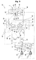
- FIG. 7 is a schematic diagram of an electricity generating and air conditioning system with a dehumidifier according to a fourth embodiment of the present invention, illustrating a state in which the system operates in a heating mode.
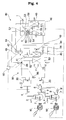
- FIG. 8 is a schematic diagram of the electricity generating and air conditioning system with the dehumidifier according to the fourth embodiment of the present invention, illustrating a state in which the system operates in a cooling mode.
Landscapes
- Engineering & Computer Science (AREA)
- Mechanical Engineering (AREA)
- General Engineering & Computer Science (AREA)
- Chemical & Material Sciences (AREA)
- Combustion & Propulsion (AREA)
- Physics & Mathematics (AREA)
- Thermal Sciences (AREA)
- Drying Of Gases (AREA)
- Compression-Type Refrigeration Machines With Reversible Cycles (AREA)
Abstract
Description
- The present invention relates to an electricity generating and air conditioning system with a dehumidifier, and, more particularly, to an electricity generating and air conditioning system with a dehumidifier in which exhaust gas or cooling water of an engine is used to achieve an improvement in air conditioning efficiency.
- In general, electricity generating and air conditioning systems generate electricity by use of a rotating force outputted from an engine, and operate an air conditioner by use of the generated electricity. Such electricity generating and air conditioning systems are mainly used for multi-type air conditioners or large-scale air conditioners.
- Such electricity generating and air conditioning systems include an engine, a generator connected to an output shaft of the engine to generate electricity, and an air conditioner, which is operated, using the electricity generated from the generator.
- However, such a conventional electricity generating and air conditioning system has a problem in that waste heat of exhaust gas discharged from an engine and waste heat of cooling water used to cool the engine are inefficiently re-used, so that the system exhibits a low energy efficiency.
- The present invention has been made in view of the above-mentioned problems, and it is an object of the invention to provide an electricity generating and air conditioning system with a dehumidifier in which waste heat of an engine is recovered to be used as a heat source to regenerate a dehumidifying agent, so that the system exhibits a maximal enhancement in efficiency.
- Another object of the invention is to provide an electricity generating and air conditioning system with a dehumidifier in which waste heat of an engine is used as a heat source to regenerate a dehumidifying agent during a cooling operation of a heat pump type air conditioner, and thus, to enhance the pleasantness of a confined space to be air-conditioned, and is used to pre-heat air blown to an outdoor heat exchanger, and thus, to reduce a heating load, so that the system exhibits a maximal enhancement in efficiency.
- In accordance with one aspect, the present invention provides an electricity generating and air conditioning system comprising: an engine; a generator connected to an output shaft of the engine to generate electricity; a dehumidifying agent body to dehumidify indoor air; a regeneration heater to regenerate the dehumidifying agent body; and waste heat recovering means to supply waste heat of the engine to the regeneration heater, and thus, to allow the regeneration heater to use the supplied waste heat as a heat source for the regeneration of the dehumidifying agent body.
- The waste heat recovering means may comprise a cooling water heat exchanger to absorb heat from cooling water used to cool the engine, an exhaust gas heat exchanger to absorb heat from exhaust gas discharged from the engine, and heat transfer means to transfer heat from at least one of the cooling water heat exchanger and the exhaust gas heat exchanger to the regeneration heater.
- In accordance with another aspect, the present invention provides an electricity generating and air conditioning system comprising: an engine; a generator connected to an output shaft of the engine to generate electricity; a heat pump type air conditioner, which comprises a compressor, a directional valve, an outdoor heat exchanger, an expansion device, and an indoor heat exchanger; a dehumidifying agent body to dehumidify indoor air; a regeneration heater to regenerate the dehumidifying agent body; and waste heat recovering means to supply waste heat of the engine to the regeneration heater, and thus, to allow the regeneration heater to use the supplied waste heat as a heat source for the regeneration of the dehumidifying agent body, or to supply the waste heat of the engine to the heat pump type air conditioner.
- The waste heat recovering means may comprise a cooling water heat exchanger to absorb heat from cooling water used to cool the engine, an exhaust gas heat exchanger to absorb heat from exhaust gas discharged from the engine, a pre-heater to pre-heat outdoor air blown to the outdoor heat exchanger, and heat transfer means to transfer heat from at least one of the cooling water heat exchanger and the exhaust gas heat exchanger to the regeneration heater during a cooling operation of the heat pump type air conditioner, and to transfer heat from at least one of the cooling water heat exchanger and the exhaust gas heat exchanger to the pre-heater during a heating operation of the heat pump type air conditioner.
- In accordance with another aspect, the present invention provides an electricity generating and air conditioning system comprising: an engine; a generator connected to an output shaft of the engine to generate electricity; a cooling water heat exchanger to absorb heat from cooling water used to cool the engine; an exhaust gas heat exchanger to absorb heat from exhaust gas discharged from the engine; a heat pump type air conditioner, which uses the electricity generated from the generator, and comprises an outdoor unit including a compressor, a directional valve, an outdoor heat exchanger, and an expansion device, and an indoor unit including an indoor heat exchanger; a dehumidifying agent body to dehumidify indoor air; a regeneration heater arranged in the indoor unit to regenerate the dehumidifying agent body; a pre-heater to pre-heat outdoor air blown to the outdoor heat exchanger; and heat transfer means to transfer heat from at least one of the cooling water heat exchanger and the exhaust gas heat exchanger to the regeneration heater during a cooling operation of the heat pump type air conditioner, and to transfer heat from at least one of the cooling water heat exchanger and the exhaust gas heat exchanger to the pre-heater during a heating operation of the heat pump type air conditioner.
- At least one of the engine, the generator, the indoor heat exchanger, the dehumidifying agent body, the regeneration heater, and the outdoor heat exchanger may comprise a plurality of ones.
- The heat transfer means may comprise a pre-heater circulation conduit to guide a heat medium to be circulated through the cooling water heat exchanger, the exhaust gas heat exchanger, and the pre-heater, and a regeneration heater circulation conduit to guide the heat medium to be circulated through the cooling water heat exchanger, the exhaust gas heat exchanger, and the regeneration heater.
- The regeneration heater circulation conduit may be branched from the pre-heater circulation conduit.
- The heat transfer means may further comprise a heat medium circulation pump to pump the heat medium, and thus, to circulate the heat medium through the pre-heater circulation conduit or through the regeneration heater circulation conduit.
- The heat transfer means may further comprise a control valve to alternately open/close the pre-heater circulation conduit and the regeneration heater circulation conduit.
- The heat transfer means may further comprise a controller to control the control valve to operate, during a cooling operation of the heat pump type air conditioner, in a cooling mode in which the regeneration heater circulation conduit is opened, and the pre-heater circulation conduit is closed, and to control the control valve to operate, during a heating operation of the heat pump type air conditioner, in a heating mode in which the regeneration heater circulation conduit is closed, and the pre-heater circulation conduit is opened.
- The electricity generating and air conditioning system according to the present invention has an advantage in that the waste heat of the engine is used as a heat source to regenerate the dehumidifying agent body, so that the system exhibits a high energy efficiency.
- The electricity generating and air conditioning system according to the present invention also has advantages in that the waste heat of the engine is used as a heat source to regenerate the dehumidifying agent body during a cooling operation of the heat pump type air conditioner, and thus, to enhance the pleasantness of a confined space to be air-conditioned, and is used to pre-heat air blown to the outdoor heat exchanger, and thus, to reduce a heating load, so that the system exhibits a maximal enhancement in efficiency.
- In addition, the electricity generating and air conditioning system according to the present invention has advantages in that the regeneration heater circulation conduit is branched from the pre-heater circulation conduit such that only one heat medium conduit is provided for both the cooling water heat exchanger and the exhaust gas heat exchanger, so that the circulation conduit structure for the cooling water heat exchanger and exhaust gas heat exchanger is simple, and the number of control valves to be used for the circulation of the heat medium is minimized.
- The above objects, and other features and advantages of the present invention will become more apparent after reading the following detailed description when taken in conjunction with the drawings, in which:
- FIG. 1 is a schematic diagram of an electricity generating and air conditioning system with a dehumidifier according to a first embodiment of the present invention, illustrating a state in which the system operates in a heating mode;
- FIG. 2 is a schematic diagram of the electricity generating and air conditioning system with the dehumidifier according to the first embodiment of the present invention, illustrating a state in which the system operates in a cooling mode;
- FIG. 3 is a schematic diagram of an electricity generating and air conditioning system with a dehumidifier according to a second embodiment of the present invention, illustrating a state in which the system operates in a heating mode;
- FIG. 4 is a schematic diagram of the electricity generating and air conditioning system with the dehumidifier according to the second embodiment of the present invention, illustrating a state in which the system operates in a cooling mode;
- FIG. 5 is a schematic diagram of an electricity generating and air conditioning system with a dehumidifier according to a third embodiment of the present invention, illustrating a state in which the system operates in a heating mode;
- FIG. 6 is a schematic diagram of the electricity generating and air conditioning system with the dehumidifier according to the third embodiment of the present invention, illustrating a state in which the system operates in a cooling mode;
- FIG. 7 is a schematic diagram of an electricity generating and air conditioning system with a dehumidifier according to a fourth embodiment of the present invention, illustrating a state in which the system operates in a heating mode; and
- FIG. 8 is a schematic diagram of the electricity generating and air conditioning system with the dehumidifier according to the fourth embodiment of the present invention, illustrating a state in which the system operates in a cooling mode.
- Hereinafter, exemplary embodiments of an electricity generating and air conditioning system according to the present invention will be described with reference to the annexed drawings.
- FIG. 1 is a schematic diagram of an electricity generating and air conditioning system with a dehumidifier according to a first embodiment of the present invention, illustrating a state in which the system operates in a heating mode. FIG. 2 is a schematic diagram of the electricity generating and air conditioning system with the dehumidifier according to the first embodiment of the present invention, illustrating a state in which the system operates in a cooling mode.
- As shown in FIGS. 1 and 2, the electricity generating and air conditioning system includes an
engine 2, agenerator 10 connected to an output shaft of theengine 2 to generate electricity, a coolingwater heat exchanger 20 to absorb heat from cooling water used to cool theengine 2, and an exhaustgas heat exchanger 30 to absorb heat from exhaust gas discharged from theengine 2. The electricity generating and air conditioning system also includes a heat pumptype air conditioner 40, which uses the electricity generated from thegenerator 10, and includes acompressor 41, adirectional valve 42, anindoor heat exchanger 43, anexpansion device 44, and anoutdoor heat exchanger 45. The electricity generating and air conditioning system further includes adehumidifying agent body 50 to dehumidify indoor air, aregeneration heater 60 to regenerate thedehumidifying agent body 50, a pre-heater 70 to pre-heat air blown toward theoutdoor heat exchanger 45, and a heat transfer means 80 to transfer heat from at least one of the coolingwater heat exchanger 20 and exhaustgas heat exchanger 30 to theregeneration heater 60 during a cooling operation of the heat pumptype air conditioner 40, and to transfer heat from at least one of the coolingwater heat exchanger 20 and exhaustgas heat exchanger 30 to the pre-heater 70 during a heating operation of the heat pumptype air conditioner 40. - The
engine 2 includes a combustion chamber defined in the interior of theengine 2. - A
fuel tube 3 and anexhaust tube 4 are connected to theengine 2. Thefuel tube 3 is adapted to supply fuel such as liquefied gas or liquefied petroleum gas into the combustion chamber. Theexhaust tube 4 is adapted to guide exhaust gas discharged from the combustion chamber. - The
exhaust tube 4 is arranged between theengine 2 and the exhaustgas heat exchanger 30 to guide exhaust gas E discharged from theengine 2 to the exhaustgas heat exchanger 30. - The cooling
water heat exchanger 20 is connected to theengine 2 via coolingwater circulation conduits engine 2, transfers heat to the coolingwater heat exchanger 20 while passing through the coolingwater heat exchanger 20, and is then again circulated into theengine 2. - A cooling
water circulation pump 9 is connected to one of theengine 2, coolingwater heat exchanger 20, and coolingwater circulation conduits - The
generator 10 may be an AC generator or a DC generator. - In a heating operation of the heat pump
type air conditioner 40, refrigerant, which has been compressed in thecompressor 41, flows through thedirectional valve 42,indoor heat exchanger 43,expansion device 44,outdoor heat exchanger 45, anddirectional valve 42, in this order, and then enters thecompressor 41, as shown in FIG. 1. Thus, the refrigerant is circulated. In this operation, theoutdoor heat exchanger 45 functions as an evaporator, whereas theindoor heat exchanger 43 functions as a condenser, and thus, discharges heat to indoor air. - On the other hand, in a cooling operation of the
air conditioner 40, refrigerant, which has been compressed in thecompressor 41, flows through thedirectional valve 42,outdoor heat exchanger 45,expansion device 44,indoor heat exchanger 43, anddirectional valve 42, in this order, and then enters thecompressor 41, as shown in FIG. 2. Thus, the refrigerant is circulated. In this operation, theoutdoor heat exchanger 45 functions as a condenser, whereas theindoor heat exchanger 43 functions as an evaporator, and thus, absorbs heat from indoor air. - The heat pump
type air conditioner 40 further includes an indoor fan orblower 47 to blow indoor air I to theindoor heat exchanger 43. Theindoor heat exchanger 43,indoor fan 47,dehumidifying agent body 50, andregeneration heater 60 constitute anindoor unit 46 of the heat pumptype air conditioner 40. - The heat pump
type air conditioner 40 further includes an outdoor fan orblower 49 to blow outdoor air O to theoutdoor heat exchanger 45. Thecompressor 41,directional valve 42,expansion device 44,outdoor heat exchanger 45, andoutdoor fan 49 constitute anoutdoor unit 48 of the heat pumptype air conditioner 40. - The
dehumidifying agent body 50 andregeneration heater 60 constitute adehumidifier 52, which is also included in the heat pumptype air conditioner 40. - The interior of the
dehumidifier 52 is partitioned by abarrier 55 to define adehumidifying chamber 53, through which indoor air blown toward theindoor heat exchanger 43 passes, and aregeneration chamber 54, through which outdoor air to regenerate thedehumidifying agent body 50 passes. - The
dehumidifying agent body 50 extends through thebarrier 55 such that a portion of thedehumidifying agent body 50 is arranged in thedehumidifying chamber 53, and the remaining portion of thedehumidifying agent body 50 is arranged in theregeneration chamber 54. - The
regeneration heater 60 is arranged in theregeneration chamber 54. - The
dehumidifier 52 further includes a driving means 56 such as a motor to rotate thedehumidifying agent body 50 such that the portion of thedehumidifying agent body 50, which is arranged in thedehumidifying chamber 53, is moved to theregeneration chamber 54 after dehumidifying indoor air in thedehumidifying chamber 53 so that the portion of thedehumidifying agent body 50 is dehumidified in theregeneration chamber 54 by theregeneration heater 60. - The
dehumidifier 52 further includes a regeneration fan orblower 57 to blow outdoor air ○ such that the outdoor air ○ passes through thedehumidifying agent body 50 in a state of being heated by theregeneration heater 60 while passing through theregeneration heater 60, and is then discharged to the atmosphere. - The pre-heater 70 is arranged upstream from the
outdoor heat exchanger 45 with respect to a flowing direction of outdoor air O blown toward theoutdoor heat exchanger 45, to pre-heat the outdoor air O. - The heat transfer means 80 may be configured to absorb waste heat from only one of the cooling
water heat exchanger 20 and exhaustgas heat exchanger 30. Alternatively, the heat transfer means 80 may be configured to absorb waste heat from both the coolingwater heat exchanger 20 and the exhaustgas heat exchanger 30 in an independent manner. The following description will be given only in conjunction with the case in which the heat transfer means 80 absorbs waste heat from both the coolingwater heat exchanger 20 and the exhaustgas heat exchanger 30 in an independent manner. - The heat transfer means 80 includes a
pre-heater circulation conduit 82 to guide a heat medium to be circulated through the coolingwater heat exchanger 20, exhaustgas heat exchanger 30, and pre-heater 70, and a regenerationheater circulation conduit 84 to guide the heat medium to be circulated through the coolingwater heat exchanger 20, exhaustgas heat exchanger 30, andregeneration heater 60. - The
pre-heater circulation conduit 82 and regenerationheater circulation conduit 84 of the heat transfer means 80 may be independent of each other such that a first heat medium is circulated through thepre-heater circulation conduit 82, and a second heat medium is circulated through the regenerationheater circulation conduit 84. Alternatively, the regenerationheater circulation conduit 84 may be branched from thepre-heater circulation conduit 82 such that a heat medium is selectively circulated through thepre-heater circulation conduit 82 or regenerationheater circulation conduit 84. The following description will be given only in conjunction with the case in which the regenerationheater circulation conduit 84 is branched from thepre-heater circulation conduit 82. - The heat transfer means 80 further includes a heat
medium circulation pump 86 to pump the heat medium, and thus, to circulate the heat medium through thepre-heater circulation conduit 82 or regenerationheater circulation conduit 84. - The heat transfer means 80 further includes a
control valve 88 to alternately open/close thepre-heater circulation conduit 82 and regenerationheater circulation conduit 84. - Although only one
control valve 88 is arranged at a connection region where the regenerationheater circulation conduit 84 is branched from thepre-heater circulation conduit 82, to alternately open/close thepre-heater circulation conduit 82 and regenerationheater circulation conduit 84, in the illustrated case, twocontrol valves 88 may be arranged at both thepre-heater circulation conduit 82 and regenerationheater circulation conduit 84, to open/close theconduits control valve 88 is arranged to alternately open/close thepre-heater circulation conduit 82 and regenerationheater circulation conduit 84. - The heat transfer means 80 further includes a
controller 90 to control thecontrol valve 88 to operate, during a cooling operation of the heat pumptype air conditioner 40, in a cooling mode in which the regenerationheater circulation conduit 84 is opened, and thepre-heater circulation conduit 82 is closed, and to control thecontrol valve 88 to operate, during a heating operation of the heat pumptype air conditioner 40, in a heating mode in which the regenerationheater circulation conduit 84 is closed, and thepre-heater circulation conduit 82 is opened. - Hereinafter, operation of the system having the above-described arrangement will be described.
- When fuel is supplied to the
engine 2 via thefuel tube 3, and theengine 2 is subsequently driven, the output shaft of theengine 2 is rotated, thereby causing thegenerator 10 to generate electricity. - Exhaust gas, which is discharged from the
engine 2 during the operation of theengine 2, is fed to the exhaustgas heat exchanger 30, and is then discharged to the atmosphere after releasing its heat into the exhaustgas heat exchanger 30. - During the operation of the
engine 2, the coolingwater circulation pump 9 operates. In accordance with the operation of the coolingwater circulation pump 9, cooling water, which is heated while cooling theengine 2, is fed to the coolingwater heat exchanger 20 via the coolingwater circulation conduit 7, and is then circulated into theengine 2 via the coolingwater circulation conduit 8 after releasing its heat into the coolingwater heat exchanger 20. - When the heat pump
type air conditioner 40 operates in the heating mode, thecompressor 41 is driven by the electricity generated from thegenerator 10. In this case, thedirectional valve 42 is switched to a heating mode, and the heatmedium circulation pump 86 is driven. Also, thecontrol valve 88 is switched to a heating mode. - When the
directional valve 42 is switched to the heating mode, and thecompressor 41 operates, as shown in FIG. 1, thecompressor 41 compresses low-temperature and low-pressure refrigerant gas, thereby changing the refrigerant gas into a high-temperature and high-pressure state. The high-temperature and high-pressure refrigerant gas is fed into theindoor heat exchanger 43 via thedirectional valve 42, and discharges its heat to indoor air while passing through theindoor heat exchanger 43, so that the refrigerant gas is condensed. - Subsequently, the condensed refrigerant is expanded while passing through the
expansion device 44, and is then fed into theoutdoor heat exchanger 45. The expanded refrigerant absorbs heat from outdoor air while passing through theoutdoor heat exchanger 45, so that the refrigerant is evaporated. - The evaporated refrigerant is subsequently circulated into the
compressor 41 via thedirectional valve 42. As the circulation of the refrigerant is repeated, a confined space, in which indoor air is circulated, is continuously heated. - When the
control valve 88 is switched to the heating mode, and the heatmedium circulation pump 86 is driven, the heat medium heated by the coolingwater heat exchanger 20 is re-heated by the exhaustgas heat exchanger 30, and is then guided to thepre-heater circulation conduit 82, and thus, the pre-heater 70, by thecontrol valve 88. After releasing heat into the pre-heater 70, that is, heating the pre-heater 70, the heat medium is circulated into the coolingwater heat exchanger 20. As the circulation of the heat medium is repeated, the pre-heater 70 is continuously heated. - Meanwhile, the pre-heater 70, which is heated as described above, heats air blown toward the
outdoor heat exchanger 45, so that theoutdoor heat exchanger 45 is not frosted. - On the other hand, when the heat pump type air conditioner operates in a cooling mode, the
compressor 41 is driven by the electricity generated from thegenerator 10. In this case, thedirectional valve 42 is switched to the cooling mode, and the heatmedium circulation pump 86 is driven. Also, thecontrol valve 88 is switched to the cooling mode, and thedehumidifier 52 is driven. - When the
directional valve 42 is switched to the cooling mode, and thecompressor 41 operates, as shown in FIG. 2, thecompressor 41 compresses low-temperature and low-pressure refrigerant gas, thereby changing the refrigerant gas into a high-temperature and high-pressure state. The high-temperature and high-pressure refrigerant gas is fed into theoutdoor heat exchanger 45 via thedirectional valve 42, and discharges its heat to outdoor air while passing through theoutdoor heat exchanger 45, so that the refrigerant gas is condensed. - Subsequently, the condensed refrigerant is expanded while passing through the
expansion device 44, and is then fed into theindoor heat exchanger 43. The expanded refrigerant absorbs heat from indoor air while passing through theindoor heat exchanger 43, so that the refrigerant is evaporated. - The evaporated refrigerant is circulated into the
compressor 41 via thedirectional valve 42. As the circulation of the refrigerant is repeated, the confined space is continuously cooled. - Meanwhile, when the
control valve 88 is switched to the cooling mode, and the heatmedium circulation pump 86 operates, the heat medium heated by the coolingwater heat exchanger 20 is re-heated by the exhaustgas heat exchanger 30, and is then guided to the regenerationheater circulation conduit 84, and thus, theregeneration heater 60, by thecontrol valve 88. After releasing heat into theregeneration heater 60, that is, heating theregeneration heater 60, the heat medium is circulated into the coolingwater heat exchanger 20. As the circulation of the heat medium is repeated, theregeneration heater 60 is continuously heated. - When the
dehumidifier 52 is to be driven, the driving means 56 such as a motor rotates thedehumidifying agent body 50 while driving theregeneration blower 57. - During the operation of the
regeneration blower 57, outdoor air is heated by theregeneration heater 60. The heated outdoor air regenerates thedehumidifying agent body 50 while passing through thedehumidifying agent body 50, and is then discharged to the atmosphere. - FIG. 3 is a schematic diagram of an electricity generating and air conditioning system with a dehumidifier according to a second embodiment of the present invention, illustrating a state in which the system operates in a heating mode. FIG. 4 is a schematic diagram of the electricity generating and air conditioning system with the dehumidifier according to the second embodiment of the present invention, illustrating a state in which the system operates in a cooling mode.
- As shown in FIGS. 3 and 4, the electricity generating and air conditioning system includes a plurality of
engines 2, 2'.... The electricity generating and air conditioning system also includes a plurality ofgenerators 10, 10'... connected to respective shafts of theengines 2, 2'.... - One or more of the
engines 2, 2'... operate in accordance with the load to be cooled or heated. -
Fuel tubes 3, 3'... andexhaust tubes 4, 4'... are connected torespective engines 2, 2'.... Also, pairs of coolingwater circulation conduits respective engines 2, 2'.... - The
exhaust gas tubes 4, 4'... are connected in parallel. - The cooling
water circulation conduits - Cooling water circulation pumps 9, 9' ... are directly connected to the cooling
water circulation conduit - The electricity generating and air conditioning system of the second embodiment has the same configuration and functions as those of the first embodiment, except for the
engines 2, 2'... andgenerators 10, 10'.... Accordingly, the constituent elements of the second embodiment respectively corresponding to those of the first embodiment are designated by the same reference numerals, and no detailed description thereof will be given. - FIG. 5 is a schematic diagram of an electricity generating and air conditioning system with a dehumidifier according to a third embodiment of the present invention, illustrating a state in which the system operates in a heating mode. FIG. 6 is a schematic diagram of the electricity generating and air conditioning system with the dehumidifier according to the third embodiment of the present invention, illustrating a state in which the system operates in a cooling mode.
- As shown in FIGS. 5 and 6, the heat pump type air conditioner, that is, the heat pump
type air conditioner 40, which is included in the electricity generating and air conditioning system, is of a multi-type. That is, the heat pumptype air conditioner 40 includes a plurality ofindoor units 46, 46'..., and a singleoutdoor unit 48. Theindoor units 46, 46'... includeindoor heat exchangers 43, 43'..., which are connected in parallel, respectively. - The
indoor units 46, 46'... also includeindoor blowers 47, 47'..., respectively. -
Humidifiers 52, 52'..., each of which includes ahumidifying agent body 50 and aregeneration heater 60, are also included in respectiveindoor units 46, 46'.... - Each of the
dehumidifiers 52, 52'... is the same as the dehumidifier included in the electricity generating and air conditioning system according to the first embodiment of the present invention, so that no detailed description thereof will be given. - Regeneration
heater circulation conduits 84, 84'..., which are connected in parallel, guide a heat medium torespective regeneration heaters 60. - The electricity generating and air conditioning system of this embodiment has the same configuration and functions as those of the first embodiment, except that the heat pump
type air conditioner 40 includes a plurality ofindoor units 46, 46'..., a plurality ofdehumidifiers 52, 52'..., and a plurality of regenerationheater circulation conduits 84, 84'.... Accordingly, the constituent elements of the third embodiment respectively corresponding to those of the first embodiment are designated by the same reference numerals, and no detailed description thereof will be given. - FIG. 7 is a schematic diagram of an electricity generating and air conditioning system with a dehumidifier according to a fourth embodiment of the present invention, illustrating a state in which the system operates in a heating mode. FIG. 8 is a schematic diagram of the electricity generating and air conditioning system with the dehumidifier according to the fourth embodiment of the present invention, illustrating a state in which the system operates in a cooling mode.
- As shown in FIGS. 7 and 8, the heat pump type air conditioner, that is, the heat pump
type air conditioner 40, which is included in the electricity generating and air conditioning system, includes a plurality ofindoor units 46, 46'..., and a plurality ofoutdoor units 48, 48'.... - In the heat pump
type air conditioner 40, refrigerant conduits respectively included in theindoor units 46, 46'... may be connected in parallel. Refrigerant conduits respectively included in theoutdoor units 48, 48'... may also be connected in parallel. The following description will be given in conjunction with the case in which each of theoutdoor units 48, 48'... are connected to an associated one of theindoor units 46, 46'... to constitute one air conditioner set, and each air conditioner set operates independently of other air conditioner sets. - The
indoor units 46, 46'... include respectiveindoor heat exchangers 43, 43'..., and respectiveindoor blowers 47, 47'.... -
Humidifiers 52, 52'..., each of which includes ahumidifying agent body 50 and aregeneration heater 60, are also included in respectiveindoor units 46, 46'.... - Each of the
dehumidifiers 52, 52'... is the same as the dehumidifier included in the electricity generating and air conditioning system according to the first embodiment of the present invention, so that no detailed description thereof will be given. - The
outdoor units 48, 48'... includerespective compressors 41, 41'...,directional valves 42, 42'...,respective expansion devices 44, 44' ..., respectiveoutdoor heat exchangers 45, 45' ..., and respectiveoutdoor blowers 49, 49'.... - Pre-heaters 70, 70'... are arranged upstream from respective
outdoor heat exchangers 45, 45'... to pre-heat outdoor air blown to theoutdoor heat exchangers 45, 45'..., respectively. - First
pre-heater circulation conduits 82, 82'..., which are connected in parallel, are connected torespective pre-heaters 70, 70'.... to guide a heat medium to be circulated through the pre-heaters 70, 70'.... - Regeneration
heater circulation conduits 84, 84'..., which are connected in parallel, are connected torespective regeneration heaters 60... to guide a heat medium to be circulated through theregeneration heaters 60.... - The electricity generating and air conditioning system of this embodiment has the same configuration and functions as those of the first embodiment, except that the heat pump
type air conditioner 40 includes a plurality ofindoor units 46, 46'..., a plurality ofdehumidifiers 52, 52'..., a plurality ofoutdoor units 48, 48'..., a plurality ofpre-heaters 70, 70'..., a plurality ofpre-heater circulation conduits 82, 82'..., and a plurality of regenerationheater circulation conduits 84, 84'.... Accordingly, the constituent elements of the fourth embodiment respectively corresponding to those of the first embodiment are designated by the same reference numerals, and no detailed description thereof will be given. - The electricity generating and air conditioning system with the dehumidifier according to any one of the above-described embodiments of the present invention has various effects.
- That is, the electricity generating and air conditioning system according to the present invention has an advantage in that the waste heat of the engine is used as a heat source to regenerate the dehumidifying agent body included in the dehumidifier, so that the system exhibits a high energy efficiency.
- The electricity generating and air conditioning system according to the present invention also has advantages in that the waste heat of the engine is used as a heat source to regenerate the dehumidifying agent body during a cooling operation of the heat pump type air conditioner, and thus, to enhance the pleasantness of a confined space to be air-conditioned, and is used to pre-heat air blown to the outdoor heat exchanger, and thus, to reduce a heating load, so that the system exhibits a maximal enhancement in efficiency.
- In addition, the electricity generating and air conditioning system according to the present invention has advantages in that the regeneration heater circulation conduit is branched from the pre-heater circulation conduit such that only one heat medium conduit is provided for both the cooling water heat exchanger and the exhaust gas heat exchanger, so that the circulation conduit structure for the cooling water heat exchanger and exhaust gas heat exchanger is simple, and the number of control valves to be used for the circulation of the heat medium is minimized.
- Although the preferred embodiments of the invention have been disclosed for illustrative purposes, those skilled in the art will appreciate that various modifications, additions and substitutions are possible, without departing from the scope and spirit of the invention as disclosed in the accompanying claims.
Claims (11)
- An electricity generating and air conditioning system comprising:an engine;a generator connected to an output shaft of the engine to generate electricity;a dehumidifying agent body to dehumidify indoor air;a regeneration heater to regenerate the dehumidifying agent body; andwaste heat recovering means to supply waste heat of the engine to the regeneration heater, and thus, to allow the regeneration heater to use the supplied waste heat as a heat source for the regeneration of the dehumidifying agent body.
- The electricity generating and air conditioning system according to claim 1, wherein the waste heat recovering means comprises:a cooling water heat exchanger to absorb heat from cooling water used to cool the engine;an exhaust gas heat exchanger to absorb heat from exhaust gas discharged from the engine; andheat transfer means to transfer heat from at least one of the cooling water heat exchanger and the exhaust gas heat exchanger to the regeneration heater.
- An electricity generating and air conditioning system comprising:an engine;a generator connected to an output shaft of the engine to generate electricity;a heat pump type air conditioner, which comprises a compressor, a directional valve, an outdoor heat exchanger, an expansion device, and an indoor heat exchanger;a dehumidifying agent body to dehumidify indoor air;a regeneration heater to regenerate the dehumidifying agent body; andwaste heat recovering means to supply waste heat of the engine to the regeneration heater, and thus, to allow the regeneration heater to use the supplied waste heat as a heat source for the regeneration of the dehumidifying agent body, or to supply the waste heat of the engine to the heat pump type air conditioner.
- The electricity generating and air conditioning system according to claim 3, wherein the waste heat recovering means comprises:a cooling water heat exchanger to absorb heat from cooling water used to cool the engine;an exhaust gas heat exchanger to absorb heat from exhaust gas discharged from the engine;a pre-heater to pre-heat outdoor air blown to the outdoor heat exchanger; andheat transfer means to transfer heat from at least one of the cooling water heat exchanger and the exhaust gas heat exchanger to the regeneration heater during a cooling operation of the heat pump type air conditioner, and to transfer heat from at least one of the cooling water heat exchanger and the exhaust gas heat exchanger to the pre-heater during a heating operation of the heat pump type air conditioner.
- An electricity generating and air conditioning system comprising:an engine;a generator connected to an output shaft of the engine to generate electricity;a cooling water heat exchanger to absorb heat from cooling water used to cool the engine;an exhaust gas heat exchanger to absorb heat from exhaust gas discharged from the engine;a heat pump type air conditioner, which uses the electricity generated from the generator, and comprises an outdoor unit including a compressor, a directional valve, an outdoor heat exchanger, and an expansion device, and an indoor unit including an indoor heat exchanger;a dehumidifying agent body to dehumidify indoor air;a regeneration heater arranged in the indoor unit to regenerate the dehumidifying agent body;a pre-heater to pre-heat outdoor air blown to the outdoor heat exchanger; andheat transfer means to transfer heat from at least one of the cooling water heat exchanger and the exhaust gas heat exchanger to the regeneration heater during a cooling operation of the heat pump type air conditioner, and to transfer heat from at least one of the cooling water heat exchanger and the exhaust gas heat exchanger to the pre-heater during a heating operation of the heat pump type air conditioner.
- The electricity generating and air conditioning system according to claim 4 or 5, wherein at least one of the engine, the generator, the indoor heat exchanger, the dehumidifying agent body, the regeneration heater, and the outdoor heat exchanger comprises a plurality of ones.
- The electricity generating and air conditioning system according to claim 4 or 5, wherein the heat transfer means comprises:a pre-heater circulation conduit to guide a heat medium to be circulated through the cooling water heat exchanger, the exhaust gas heat exchanger, and the pre-heater; anda regeneration heater circulation conduit to guide the heat medium to be circulated through the cooling water heat exchanger, the exhaust gas heat exchanger, and the regeneration heater.
- The electricity generating and air conditioning system according to claim 7, wherein the regeneration heater circulation conduit is branched from the pre-heater circulation conduit.
- The electricity generating and air conditioning system according to claim 7, wherein the heat transfer means further comprises a heat medium circulation pump to pump the heat medium, and thus, to circulate the heat medium through the pre-heater circulation conduit or through the regeneration heater circulation conduit.
- The electricity generating and air conditioning system according to claim 7, wherein the heat transfer means further comprises a control valve to alternately open/close the pre-heater circulation conduit and the regeneration heater circulation conduit.
- The electricity generating and air conditioning system according to claim 10, wherein the heat transfer means further comprises a controller to control the control valve to operate, during a cooling operation of the heat pump type air conditioner, in a cooling mode in which the regeneration heater circulation conduit is opened, and the pre-heater circulation conduit is closed, and to control the control valve to operate, during a heating operation of the heat pump type air conditioner, in a heating mode in which the regeneration heater circulation conduit is closed, and the pre-heater circulation conduit is opened.
Applications Claiming Priority (1)
| Application Number | Priority Date | Filing Date | Title |
|---|---|---|---|
| KR1020040064817A KR100550575B1 (en) | 2004-08-17 | 2004-08-17 | Power generation air conditioning system with dehumidifier |
Publications (2)
| Publication Number | Publication Date |
|---|---|
| EP1628103A2 true EP1628103A2 (en) | 2006-02-22 |
| EP1628103A3 EP1628103A3 (en) | 2006-11-08 |
Family
ID=36080341
Family Applications (1)
| Application Number | Title | Priority Date | Filing Date |
|---|---|---|---|
| EP05001454A Withdrawn EP1628103A3 (en) | 2004-08-17 | 2005-01-25 | Electricity generating and air conditioning system with dehumidifier |
Country Status (4)
| Country | Link |
|---|---|
| US (1) | US7305840B2 (en) |
| EP (1) | EP1628103A3 (en) |
| KR (1) | KR100550575B1 (en) |
| CN (1) | CN1737456A (en) |
Cited By (1)
| Publication number | Priority date | Publication date | Assignee | Title |
|---|---|---|---|---|
| EP1966547A4 (en) * | 2007-02-01 | 2014-02-26 | Korea Distr Heating Corp | AIR CONDITIONING SYSTEM USING COOLING DEHUMIDIFICATION DEVICE |
Families Citing this family (17)
| Publication number | Priority date | Publication date | Assignee | Title |
|---|---|---|---|---|
| US7503184B2 (en) * | 2006-08-11 | 2009-03-17 | Southwest Gas Corporation | Gas engine driven heat pump system with integrated heat recovery and energy saving subsystems |
| KR20080015264A (en) * | 2006-08-14 | 2008-02-19 | 엘지전자 주식회사 | Cogeneration |
| KR100773435B1 (en) | 2007-02-01 | 2007-11-05 | 한국지역난방공사 | Dehumidification air conditioner for district heating |
| KR100773434B1 (en) * | 2007-02-01 | 2007-11-05 | 한국지역난방공사 | Dehumidification air conditioner for district heating |
| JP5636297B2 (en) * | 2011-01-24 | 2014-12-03 | ヤンマー株式会社 | Cogeneration system |
| US10036347B1 (en) | 2013-07-19 | 2018-07-31 | Raymond C. Sherry | Standby energy generating system |
| CN104514586B (en) * | 2013-09-30 | 2017-05-31 | 上海汽车集团股份有限公司 | Rankine cycle system, heat recovery system and its control method |
| EP3114411A4 (en) * | 2014-02-16 | 2017-12-20 | BE Power Tech, Inc. | Heat and mass transfer device and systems including the same |
| US9795919B2 (en) | 2014-03-21 | 2017-10-24 | 2525 Group, Inc. | Recycling of waste heat by dehumidifier appliance: apparatus and method |
| CN105276856B (en) * | 2014-06-13 | 2019-05-28 | 松下知识产权经营株式会社 | Gas heat pump air conditioning system |
| WO2019005678A1 (en) * | 2017-06-27 | 2019-01-03 | Imby Energy, Inc. | Cogeneration systems and methods for generating heating and electricity |
| DE102018105722A1 (en) * | 2018-03-13 | 2019-09-19 | Eisenmann Se | Conditioning device, treatment plant with a conditioning device and method for operating a conditioning device |
| CN114608086A (en) * | 2022-01-21 | 2022-06-10 | 汉福启东空气处理设备有限公司 | Mix type new trend dehumidifier |
| JP7469830B2 (en) * | 2022-06-14 | 2024-04-17 | ライズピットカンパニー株式会社 | Gas engine heating and cooling unit |
| JP7231969B1 (en) | 2022-06-14 | 2023-03-02 | ライズピットカンパニー株式会社 | gas engine air conditioner |
| CN115325783B (en) * | 2022-07-20 | 2023-08-22 | 广西电网有限责任公司电力科学研究院 | A control system for a heat pump drying system for preserved fruit |
| KR102621570B1 (en) * | 2023-05-09 | 2024-01-05 | 주식회사 지헨이앤씨 | System for Constant Temperature and Humidity |
Family Cites Families (21)
| Publication number | Priority date | Publication date | Assignee | Title |
|---|---|---|---|---|
| US2122013A (en) * | 1933-12-01 | 1938-06-28 | Gen Motors Corp | Refrigerating apparatus |
| US3559724A (en) | 1968-11-21 | 1971-02-02 | American Gas Ass | Comfort conditioning system |
| US4635446A (en) | 1981-05-15 | 1987-01-13 | Camp Dresser & Mckee | Dehumidification apparatus |
| US4380909A (en) | 1981-07-17 | 1983-04-26 | Chevron Research Company | Method and apparatus for co-generation of electrical power and absorption-type heat pump air conditioning |
| US4614090A (en) | 1985-01-31 | 1986-09-30 | Yanmar Diesel Engine Co. Ltd. | Outdoor unit of an air conditioner of an engine heat pump type |
| US5181387A (en) | 1985-04-03 | 1993-01-26 | Gershon Meckler | Air conditioning apparatus |
| US4700550A (en) * | 1986-03-10 | 1987-10-20 | Rhodes Barry V | Enthalpic heat pump desiccant air conditioning system |
| EP0263166A4 (en) | 1986-03-19 | 1991-07-31 | Purdue, John C. | Air conditioning apparatus |
| US4987750A (en) * | 1986-07-08 | 1991-01-29 | Gershon Meckler | Air conditioning apparatus |
| US4819444A (en) | 1986-07-08 | 1989-04-11 | Manville Sales Corporation | Air conditioning apparatus |
| US4735061A (en) | 1987-09-02 | 1988-04-05 | Hsieh Sheng Ming | Energy-saving system for an engine-driving air conditioning system |
| US5003788A (en) | 1989-09-05 | 1991-04-02 | Gas Research Institute | Gas engine driven heat pump system |
| DE19740398C2 (en) | 1997-09-09 | 1999-12-02 | Vng Verbundnetz Gas Ag | Combined heat and power facility for energy supply |
| JPH11132593A (en) | 1997-10-29 | 1999-05-21 | Daikin Ind Ltd | Air conditioner |
| JP2000274734A (en) | 1999-03-26 | 2000-10-06 | Ebara Corp | Fuel cell exhaust heat utilizing air-conditioning device |
| US6196469B1 (en) | 1999-07-28 | 2001-03-06 | Frederick J Pearson | Energy recycling air handling system |
| JP2001280745A (en) | 2000-03-31 | 2001-10-10 | Mitsubishi Heavy Ind Ltd | Air conditioner |
| JP2002130743A (en) | 2000-10-30 | 2002-05-09 | Mitsubishi Heavy Ind Ltd | Outdoor heat exchanger unit structure, outdoor unit and gas heat pump air conditioner |
| JP2002168539A (en) | 2000-12-01 | 2002-06-14 | Tokyo Gas Co Ltd | Multi type air conditioner |
| JP2003075019A (en) | 2001-08-31 | 2003-03-12 | Mitsubishi Heavy Ind Ltd | Gas heat pump type air conditioning device and combustion device for heating exhaust gas |
| NL1025293C1 (en) | 2004-01-21 | 2005-03-07 | Trs Transportkoeling B V | Cooling system for cooling a cooling room in a vehicle. |
-
2004
- 2004-08-17 KR KR1020040064817A patent/KR100550575B1/en not_active Expired - Fee Related
-
2005
- 2005-01-24 US US11/039,852 patent/US7305840B2/en not_active Expired - Fee Related
- 2005-01-25 EP EP05001454A patent/EP1628103A3/en not_active Withdrawn
- 2005-02-05 CN CNA2005100068999A patent/CN1737456A/en active Pending
Cited By (1)
| Publication number | Priority date | Publication date | Assignee | Title |
|---|---|---|---|---|
| EP1966547A4 (en) * | 2007-02-01 | 2014-02-26 | Korea Distr Heating Corp | AIR CONDITIONING SYSTEM USING COOLING DEHUMIDIFICATION DEVICE |
Also Published As
| Publication number | Publication date |
|---|---|
| CN1737456A (en) | 2006-02-22 |
| US20060037350A1 (en) | 2006-02-23 |
| KR100550575B1 (en) | 2006-02-10 |
| US7305840B2 (en) | 2007-12-11 |
| EP1628103A3 (en) | 2006-11-08 |
Similar Documents
| Publication | Publication Date | Title |
|---|---|---|
| US7240503B2 (en) | Electricity generating and air conditioning system with dehumidifier | |
| US7305840B2 (en) | Electricity generating and air conditioning system with dehumidifier | |
| EP1734317B1 (en) | Cogeneration system | |
| US4071080A (en) | Air conditioning system | |
| US7145258B2 (en) | Electricity generating and air conditioning system | |
| US7170191B2 (en) | Electricity generating and air conditioning system with water heater | |
| US7275382B2 (en) | Cogeneration system | |
| EP1628095A2 (en) | Air conditioning system combined with an electricity generating system | |
| US7600695B2 (en) | Cogeneration system and method for controlling the same | |
| EP1628099B1 (en) | Cogeneration system and method for controlling the same | |
| EP1628104A2 (en) | Cogeneration system | |
| KR20180113712A (en) | Air conditioner for vehicles | |
| EP1628097A2 (en) | Air conditioning system combined with an electricity generating system | |
| JP4182494B2 (en) | Large temperature difference air conditioning system | |
| JP4647399B2 (en) | Ventilation air conditioner | |
| WO2020246305A1 (en) | Vehicle air conditioning device | |
| JP2017009187A (en) | Air conditioner | |
| CN115703323B (en) | Vehicle air conditioning system | |
| KR20040059533A (en) | A Multi Type GHP Air Conditioner System | |
| JP4262901B2 (en) | Refrigeration equipment | |
| JPH04155A (en) | Air compression type refrigeration cycle apparatus | |
| KR20050078878A (en) | System for cooling or heating a room | |
| KR20050080472A (en) | Multi-heat pump type air conditioner |
Legal Events
| Date | Code | Title | Description |
|---|---|---|---|
| PUAI | Public reference made under article 153(3) epc to a published international application that has entered the european phase |
Free format text: ORIGINAL CODE: 0009012 |
|
| 17P | Request for examination filed |
Effective date: 20050125 |
|
| AK | Designated contracting states |
Kind code of ref document: A2 Designated state(s): AT BE BG CH CY CZ DE DK EE ES FI FR GB GR HU IE IS IT LI LT LU MC NL PL PT RO SE SI SK TR |
|
| AX | Request for extension of the european patent |
Extension state: AL BA HR LV MK YU |
|
| PUAL | Search report despatched |
Free format text: ORIGINAL CODE: 0009013 |
|
| AK | Designated contracting states |
Kind code of ref document: A3 Designated state(s): AT BE BG CH CY CZ DE DK EE ES FI FR GB GR HU IE IS IT LI LT LU MC NL PL PT RO SE SI SK TR |
|
| AX | Request for extension of the european patent |
Extension state: AL BA HR LV MK YU |
|
| AKX | Designation fees paid |
Designated state(s): DE FR GB |
|
| 17Q | First examination report despatched |
Effective date: 20120518 |
|
| STAA | Information on the status of an ep patent application or granted ep patent |
Free format text: STATUS: THE APPLICATION IS DEEMED TO BE WITHDRAWN |
|
| 18D | Application deemed to be withdrawn |
Effective date: 20120929 |