EP1627709A2 - Strömungsführung für druckmittelbetätigten Werkzeugen und damit ausgerüstete Werkzeugs - Google Patents
Strömungsführung für druckmittelbetätigten Werkzeugen und damit ausgerüstete Werkzeugs Download PDFInfo
- Publication number
- EP1627709A2 EP1627709A2 EP05255148A EP05255148A EP1627709A2 EP 1627709 A2 EP1627709 A2 EP 1627709A2 EP 05255148 A EP05255148 A EP 05255148A EP 05255148 A EP05255148 A EP 05255148A EP 1627709 A2 EP1627709 A2 EP 1627709A2
- Authority
- EP
- European Patent Office
- Prior art keywords
- rib
- flow guide
- cavity
- fluid
- driven tool
- Prior art date
- Legal status (The legal status is an assumption and is not a legal conclusion. Google has not performed a legal analysis and makes no representation as to the accuracy of the status listed.)
- Granted
Links
Images









Classifications
-
- B—PERFORMING OPERATIONS; TRANSPORTING
- B25—HAND TOOLS; PORTABLE POWER-DRIVEN TOOLS; MANIPULATORS
- B25F—COMBINATION OR MULTI-PURPOSE TOOLS NOT OTHERWISE PROVIDED FOR; DETAILS OR COMPONENTS OF PORTABLE POWER-DRIVEN TOOLS NOT PARTICULARLY RELATED TO THE OPERATIONS PERFORMED AND NOT OTHERWISE PROVIDED FOR
- B25F5/00—Details or components of portable power-driven tools not particularly related to the operations performed and not otherwise provided for
Definitions
- the present invention relates to pneumatically driven apparatus and, in particular, to pneumatically driven hand tools, construction methods, and the channeling of air through these tools.
- Pneumatic hand tools such as air grinders
- these hand tools have an elongated housing with a handle portion at one end and a collet or arbor for mounting various types of abrasive media at the other end.
- An air motor is typically disposed in the housing intermediate the ends for driving the arbor, the air motor being coupled to a source of pressurized air through a fluid inlet which commonly extends axially through the handle portion.
- the housing may be provided with a trigger, which may be in the form of a lever alongside the outside of the housing or a radially projecting button, adapted to be operated by a finger or fingers of the user's hand which grasps the handle, for operating an internal valve to admit air to the air motor.
- some conventional tools use a reversing valve mechanism to reverse the flow of exhaust fluid, which increases both complexity of construction and cost.
- Other known tools are constructed solely for front exhaust or rear exhaust, which require the manufacture of different parts for conversion between alternate exhaust configurations.
- This speed regulation can be accomplished with a variable regulating valve or, alternatively, with many single use permanent parts.
- Variable regulating valves typically are complex and subject to wear while single use permanent parts reduce the flexibility of converting the tool and create logistical problems in manufacturing the various parts. Both alternatives are typically costly to construct.
- pneumatic hand tools is typically accomplished by assembling components into an outer housing made of a thermoplastic such as an injection molded nylon or other plastic material. During assembly, these materials can be subject to breakage due to excessive holding forces that can be caused by holding the housing in a vise or other jig configuration.
- a thermoplastic such as an injection molded nylon or other plastic material.
- a flow guide configured for insertion in a cavity defined between an outer housing and a nested inner motor housing of a fluid driven tool and a tool incorporating the same.
- the flow guide has a longitudinal axis and includes at least two longitudinal portions disposed parallel to the longitudinal axis and defining longitudinal channel therebetween.
- At least one substantially circumferential rib portion connects the at least two longitudinal portions at points defining a plane substantially transverse to the longitudinal axis.
- a portion of the at least one rib portion located in the longitudinal channel has a thickness less than a width of the cavity surrounding the rib to define a circumferential recess that permits fluid communication in the longitudinal channel across the at least one rib.
- a fluid driven tool having an outer housing and an inner motor housing nested in the outer housing and defining a cavity therebetween.
- the cavity has a first end with a first exhaust passageway and a second end with a second exhaust passageway.
- the inner motor housing has a motor chamber with at least one inlet port for a fluid driven motor and a fluid inlet, and an inlet manifold disposed in the cavity.
- the inlet manifold has a recessed portion with a surrounding seal configured to engage the inner motor housing and connect the fluid inlet to the at least one inlet port of the inner motor housing.
- a fluid driven tool having an outer housing and an inner motor housing nested in the outer housing.
- An inner surface of the outer housing and an outer surface of the inner motor housing have portions that mate upon nesting the inner motor housing in the outer housing and provide reinforced areas for clamping regions of the outer housing located over the reinforced areas.
- intermediate components and power tools incorporating the same are provided.
- the intermediate components are structures disposed between a motor and an outer housing for directing the airflow and sealing air passages within fluid powered tools.
- an exemplary fluid power tool is shown in the form of a handheld pneumatic power tool having a grip portion with an outer housing 10, a fluid inlet 60, and an output drive spindle 18 that extends through a front exhaust cap 40 inserted into the outer housing 10.
- Shown in Fig. 2 is the grip portion of the handheld pneumatic power tool of FIG. 1 with the rotary components, including a vane motor 17 (shown in FIG. 5) and output drive spindle 18, removed.
- FIG. 3 and 4 are perspective and top views of the tool shown in FIGS. 1 and 2 with outer housing 10 removed.
- the vane motor 17, which is shown in the cross-sectional view of FIG. 5 produces rotary output for output drive spindle 18, however the present invention can be adapted for any fluid powered motor.
- a fluid driven tool is provided an outer housing 10 and an inner motor housing 30 nested in the outer housing 10 and defining a cavity 27 therebetween.
- the cavity 27 has a first end with a first exhaust passageway and a second end with a second exhaust passageway and a flow guide 22 disposed in the cavity 27.
- inner motor housing 30 is provided with a motor chamber 37 having exhaust ports 36 through which exhaust fluid from the vane motor 17 exits the inner motor housing 30.
- Inner motor housing 30 further includes a passage 31 and inlet ports 32 which are in fluid communication by an inlet manifold 26, according to the present invention as described in greater detail below.
- Supply air to vane motor 17 is provided from fluid inlet 60 via a throttle control mechanism 70 that regulates air through inlet ports 32 to vane motor 17.
- a front exhaust cap 40 having front exhaust holes 41 and a front muffling chamber 45, and a rear exhaust cap 50, having rear exhaust holes 51 and a rear muffling chamber 55, are disposed on opposite ends of outer housing 10, through which exhaust air of vane motor 17 is selectively directed from exhaust ports 36.
- FIG. 9 Shown in FIG. 9 is an exploded view illustrating exemplary intermediate components according to the present invention in the form of an inlet manifold 26 and exhaust flow guide 22, removed from inner motor housing 30.
- Flow guide 22 has at least two longitudinal portions 23 disposed parallel to a longitudinal axis of the flow guide.
- the longitudinal portions 23 define a longitudinal channel 24 between the two longitudinal portions 23 in the cavity 27.
- At least one rib portion 21 connects the at least two longitudinal portions 23 and is configured for attachment on the inner motor housing 30 in a plane substantially transverse to the longitudinal axis.
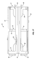
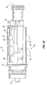
- At least one portion of the at least one rib portion 21 located in the longitudinal channel is provided with a thickness less than a width of the cavity 27 surrounding the rib portion to define at least one circumferential recess 61 that permits fluid communication in the longitudinal channel across the at least one rib portion 21.
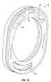
- the circumferential recess 61 can be located either on the radially outer portion of the rib (as shown best in FIGS. 12, 13, 15-17), on the radially inner portion of the rib (FIG. 27), or both (as shown best in FIGS. 25-26).
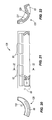
- Flow guide 22 has a sealing end shown in FIG. 14 having at least one plug 64 and an exhaust end having at least one speed regulating tab 65 shown in FIG. 15 with both ends being substantially transverse to the longitudinal axis.
- the sealing end includes at least one plug 64 for sealing at least one exhaust passageway disposed in the cavity 27.
- cavity 27 has a first end having a first exhaust passageway and a second end having a second exhaust passageway. Sealing of the first and second exhaust passageways is accomplished by inserting the at least one plug 64 of the flow guide 22 into a sealing arrangement alternately with the second and first exhaust passageways to permit fluid communication between the cavity 27 and the first and second exhaust passageways, respectively.
- a sealing wall 42 (shown in the perspective view of FIG. 10) is disposed around inner motor housing 30 having at least one aperture 143 through which the first exhaust passageway exhausts.
- the at least one aperture 143 is configured to alternately receive the at least one plug 64 and the at least one speed regulating tab 65 of the flow guide 22.
- an elastomeric surface is provided on the at least one plug 64, a face surrounding the at least one aperture 143, or both. This may be accomplished by overmolding a soft durometer material, such as a thermoplastic elastomer (TPE) or other suitable material, using a process such as that known in the art with respect to the overmolding of soft durometer handle grip materials onto tools.
- TPE thermoplastic elastomer
- the exhaust end of the flow guide 22 includes a rib portion 21 having a circumferential recess 61 that permits fluid communication in the longitudinal channel 24 across the rib portion into the corresponding exhaust passageway.
- At least one speed-regulating tab 65 may be disposed within the circumferential recess 61 on the rib portion 21 to partially restrict exhaust flow out of the tool, thereby limiting free running speed of the tool.
- flow guide 22 is axially reversed so that the compliant plugs 64 block the apertures 143 of the sealing wall 42. Exhaust air escapes past the speed regulating tabs 65, through rear muffling chamber 55, and then to atmosphere through rear exhaust holes 51 in the rear exhaust cap 50.
- the flow guide 22 may also be used to provide a framework of passages for channeling exhaust air across surfaces of the inner motor housing 30 that require cooling and obstructing flow from surfaces that do not using rib portions. Exhaust air removes heat generated by the motor vanes, thus extending vane life.
- the at least one rib portion 21 can further include at least one intermediate rib portion 20 located between the sealing and exhaust ends of the flow guide 22.
- the intermediate rib portion 20 connects the at least two longitudinal portions 23 to a third longitudinal portion 25 at points defining a plane substantially transverse to the longitudinal axis.
- third longitudinal portion 25 includes a longitudinal slot 67 that engages a spline 11 provided on the inner surface of outer housing 10 (as shown in FIG. 6) and a projection 46 provided on sealing wall 42 (shown in FIG. 10).
- One or more portions of the intermediate rib portion 20 located in the longitudinal channel are provided with a thickness less than a width of the cavity 27 surrounding the rib. These reduced thickness portions define at least one circumferential recess 61 that permits fluid communication in the longitudinal channel 24 across the intermediate rib portion 20.
- the circumferential recesses 61 may have circumferential lengths that are unequal. In this fashion, different flow volumes and flow paths of air may be provided across the surface of the inner motor housing 30 to increase or decrease air flow to particular regions, thereby optimizing cooling of these regions.
- a recessed channel 38 may be provided in inner motor housing 30 to further increase surface area to be cooled and facilitate air flow across this region.
- FIGS. 25-27 Shown in FIGS. 25-27, is a flow guide 122 in which the at least one intermediate rib portion 20 includes additional intermediate rib portions 20 disposed between the sealing and exhaust ends of the flow guide 122 to further channel air flow through cavity 27. Additionally, one or more sheet portions 62 that span between rib portions 20, 21 may also be incorporated as shown to facilitate directing air flow circumferentially within cavity 27.
- the flow guide 22 selectively directs the flow of exhaust air through either the rear or the front exhaust caps 50, 40 depending on its orientation.
- the omission of the flow guide during assembly of the tool or its subsequent removal from the tool would otherwise permit exhaust air to escape simultaneously in both directions through the front and rear exhaust caps, resulting in an increase in the free running speed of the tool.
- flow guide 22 and inner motor housing 30 have been designed with an overspeed safety feature in the event that the flow guide 22 is omitted or removed from the tool construction.
- inner motor housing 30 includes a through hole located transversely through the inner motor housing 30.
- the through hole defines an inlet passageway 31 which is in fluid communication with the fluid inlet 60, the cavity 27, and the at least one inlet port 32 of the motor chamber 37 as shown.
- At least one sealing member is provided that seals the fluid inlet 60 from the cavity 27 when the flow guide 22 is disposed in the cavity 27.
- the at least one sealing member is provided as an O-ring 68 that forms a seal between one end of inlet passageway 31 and flow guide 22 which holds the O-ring in place.
- the O-ring 68 may be disposed in a closure portion 69 located on the flow guide 22 that covers the inlet passageway 31 when the flow guide 22 is disposed in the cavity 27.
- O-ring 68 may also be sized to fit within the inlet passageway 31 and held in place by a post or boss portion (not shown) provided on the flow guide 22. It is envisioned that this latter configuration may be employed to decrease the area of inner motor housing that is covered in order to decrease heat build-up and increase the amount of cooling air circulating over the surface surrounding the blocked port.
- the inlet passageway 31 has an extra hole in the side of inner motor housing 30, which in the absence of flow guide 22, connects motive air from fluid inlet 60 to exhaust via cavity 27.
- a seal provided by O-ring 68 blocks this passage so that the tool runs at the correct speed.
- flow guide 22 is removed, high pressure air is permitted to bypass the motor 17, resulting in low speed and power. It becomes obvious to a user that something is wrong with the tool.
- an O-ring seal provided on both ends of flow guide 22 as shown, an inner motor housing port provided by one end of inlet passageway 31 is blocked regardless of whether the tool is configured for front or rear exhaust.
- FIGS. 9 and 11 Shown in FIGS. 9 and 11 is an inlet manifold 26 having a recessed portion 127 with a surrounding seal configured to engage inner motor housing 30.
- inlet manifold 26 When placed in cavity 27 as shown in FIG. 2, inlet manifold 26 connects the fluid inlet 60 to the at least one inlet port 32 of the inner motor housing 30.
- FIG. 9 the inlet manifold 26 has been removed to reveal the inlet ports 32 of the motor chamber 37.
- a motive fluid typically, air enters the tool through fluid inlet 60, as shown in FIGS. 2 and 7, passes the throttle control mechanism 70 into inlet manifold 26 via inlet passageway 31.
- the seal surrounding recessed portion 127 is preferably a pressure activated seal disposed between the inlet manifold 26 and the outer wall of the inner motor housing 30.
- the seal is an O-ring 128 disposed in an angled groove 129 around the recessed portion 127 as shown in FIGS. 11 and 23, such that upon receiving fluid pressure from the fluid inlet 60, the seal actively conforms to sealingly engage the inner motor housing 30.
- an inlet manifold 126 may also be provided with a second recessed portion 137 that is partially open to cavity 27 when inserted therein to receive fluid flow for cooling the inner motor housing 30 disposed underneath.
- a boss 130 such as that shown in FIGS. 18 and 20 is provided that does not close off, but merely engages the hole of inlet passageway 31.
- the boss 130 facilitates alignment of the recessed portion 127 over the at least one inlet port 32 and the inlet passageway 31 during insertion in cavity 27.
- a projection 66 disposed on the inlet manifold 26 is provided that inserts into a corresponding recess 144 located in sealing wall 42.
- inlet manifolds 26, 126 are molded components that are provided with reinforcing ribs 63 to reduce deflection that can result from internal pressure loading.
- the inlet manifold and flow guide form a rigid structure providing additional support in the central portion of the outer housing 10.
- assembly of a fluid driven tool is facilitated by a mating structure provided between the outer housing 10 and the inner motor housing 30.
- the mating structure assists in assembly of the tool components and is best seen in the transverse section of FIG. 8 and includes an inner surface 13 of the outer housing 10 and an outer surface 12 of the inner motor housing 30 having portions that mate upon nesting the inner motor housing 30 in the outer housing 10.
- outer clamping regions 14 Provided on the outer housing 10 are opposed outer clamping regions 14 which are connected to inner surfaces 13.
- Clamping pads 15 (shown in FIG. 1) are preferably provided in the clamping regions 14, the clamping pads 15 having a surface shape or texture to provide enhanced gripping ability.
- Outer clamping regions 14 may be connected to inner surfaces 13 by a solid wall thickness located therebetween or by spacer struts 16 as shown.
- the handle structure having this mating structure provides reinforced areas for clamping the outer housing 10 at regions 14, whereby stresses exerted thereon are transferred through and supported by the inner motor housing 30 which, preferably, is made of a metallic or other strengthened material and inserted into the inner motor housing 30 prior to clamping in a vise or other assembly fixture.
- the intermediate components of the present invention may be molded from a rigid composite material such as a glass-reinforced nylon available as CAPRON® from BASF Corporation, Germany.
- the compliant plugs and sealing portions may be molded over or otherwise attached to the framework and, preferably, are made of a soft durometer, thermoplastic elastomer (TPE) material.
- TPE thermoplastic elastomer
- compatible TPE materials for this purpose include those such as VERSAFLEX® OM6160-9 available from GLS Corporation, McHenry, IL.
Landscapes
- Engineering & Computer Science (AREA)
- Mechanical Engineering (AREA)
- Portable Power Tools In General (AREA)
- Portable Nailing Machines And Staplers (AREA)
- Valve Housings (AREA)
- Surgical Instruments (AREA)
- Dental Tools And Instruments Or Auxiliary Dental Instruments (AREA)
Applications Claiming Priority (1)
| Application Number | Priority Date | Filing Date | Title |
|---|---|---|---|
| US10/923,378 US7207394B2 (en) | 2004-08-20 | 2004-08-20 | Intermediate and assembly assistance components for fluid driven tools and tools incorporating the same |
Publications (3)
| Publication Number | Publication Date |
|---|---|
| EP1627709A2 true EP1627709A2 (de) | 2006-02-22 |
| EP1627709A3 EP1627709A3 (de) | 2007-11-21 |
| EP1627709B1 EP1627709B1 (de) | 2012-12-19 |
Family
ID=35376999
Family Applications (1)
| Application Number | Title | Priority Date | Filing Date |
|---|---|---|---|
| EP05255148A Expired - Lifetime EP1627709B1 (de) | 2004-08-20 | 2005-08-19 | Strömungsführung für druckmittelbetätigten Werkzeugen und damit ausgerüstete Werkzeugs |
Country Status (3)
| Country | Link |
|---|---|
| US (2) | US7207394B2 (de) |
| EP (1) | EP1627709B1 (de) |
| CA (2) | CA2804677C (de) |
Cited By (3)
| Publication number | Priority date | Publication date | Assignee | Title |
|---|---|---|---|---|
| FR2901501A1 (fr) * | 2006-05-23 | 2007-11-30 | Georges Renault Soc Par Action | Outil tournant pneumatique dont le moteur comprend un corps et des moyens pneumatiques distincts du corps pour la regulation et/ou la commande du sens de rotation du rotor, et moteur correspondant |
| WO2012154797A1 (en) * | 2011-05-10 | 2012-11-15 | Illinois Tool Works Inc. | Reinforced plastic sleeve for pneumatic nailer |
| EP3599061A1 (de) * | 2018-07-23 | 2020-01-29 | Stanley Black & Decker, Inc. | Motorgehäuseabluftsystem |
Families Citing this family (20)
| Publication number | Priority date | Publication date | Assignee | Title |
|---|---|---|---|---|
| US6932166B1 (en) * | 2002-12-03 | 2005-08-23 | Paul Kirsch | Pneumatic tool |
| US7207394B2 (en) * | 2004-08-20 | 2007-04-24 | Ingersoll-Rand Company | Intermediate and assembly assistance components for fluid driven tools and tools incorporating the same |
| US20070166182A1 (en) * | 2006-01-19 | 2007-07-19 | Mighty Seven International Co., Ltd. | Pneumatic tool |
| US7401662B2 (en) * | 2006-07-06 | 2008-07-22 | Honsa Ergonomic Technologies, Inc. | Powered hand tool |
| US20080264662A1 (en) * | 2007-04-24 | 2008-10-30 | Mighty Seven International Co., Ltd. | Right-handed and reverse air channel button for a pneumatic tool |
| TW200911478A (en) * | 2007-09-12 | 2009-03-16 | Cheng Huan Industry Ltd | Reciprocal pneumatic tool structure |
| ITMI20080407U1 (it) * | 2008-12-11 | 2010-06-12 | Valentini Guido | Impugnatura per macchine pneumatiche per la lavorazione di superfici |
| USD682648S1 (en) | 2012-05-25 | 2013-05-21 | Ingersoll-Rand Company | Hand-held power tool |
| USD682647S1 (en) | 2012-05-25 | 2013-05-21 | Ingersoll-Rand Company | Hand-held power tool |
| USD702099S1 (en) | 2012-05-25 | 2014-04-08 | Ingersoll-Rand Company | Angle head for a grinder or sander |
| USD694083S1 (en) | 2012-05-25 | 2013-11-26 | Ingersoll-Rand Company | Angle head for a grinder or sander |
| US9126322B2 (en) * | 2012-05-25 | 2015-09-08 | Ingersoll-Rand Company | Power tools with an internal metal housing attached to an outer composite sleeve |
| US9683379B2 (en) * | 2012-06-01 | 2017-06-20 | Time Manufacturing Company | Apparatuses and methods for providing high electrical resistance for aerial work platform components |
| WO2014036003A1 (en) | 2012-08-27 | 2014-03-06 | Ingersoll-Rand Company | Power tool housing construction |
| US20140360744A1 (en) * | 2013-06-05 | 2014-12-11 | Campbell Hausfeld / Scott Fetzer Company | Handheld pneumatic tools having pressure regulator |
| TW201700231A (zh) * | 2015-06-18 | 2017-01-01 | Jih I Pneumatic Industrial Co Ltd | 氣動工具之排氣裝置 |
| TWI579119B (zh) * | 2016-05-19 | 2017-04-21 | 日溢企業有限公司 | Pneumatic tool exhaust device |
| US11759939B2 (en) * | 2018-06-29 | 2023-09-19 | Atlas Copco Industrial Technique Ab | Handheld electric power tool |
| USD942829S1 (en) * | 2019-10-17 | 2022-02-08 | Atlas Copco Industrial Technique Ab | Power tool |
| US11691261B2 (en) * | 2020-06-02 | 2023-07-04 | Snap-On Incorporated | Housing clamp for a power tool |
Family Cites Families (40)
| Publication number | Priority date | Publication date | Assignee | Title |
|---|---|---|---|---|
| US1862223A (en) | 1920-02-05 | 1932-06-07 | Rotor Air Tool Company | Governor controlled fluid pressure tool |
| US2099280A (en) | 1933-10-21 | 1937-11-16 | William H Keller Inc | Portable pressure fluid actuated tool |
| US2514914A (en) | 1945-08-06 | 1950-07-11 | Reed Roller Bit Co | Impact wrench |
| US2543979A (en) | 1946-01-31 | 1951-03-06 | Chicago Pneumatic Tool Co | Impact wrench torque control |
| US3097571A (en) | 1961-09-05 | 1963-07-16 | Thor Power Tool Co | Rotary fluid motor |
| US3753469A (en) * | 1969-07-15 | 1973-08-21 | H Tuttle | Air tool |
| US3983947A (en) * | 1974-09-24 | 1976-10-05 | William Richard Wills | Valve and handle for an air operated tool, and method of fluid control |
| US4236589A (en) | 1978-12-26 | 1980-12-02 | Vern Griffith | Vacuum motor |
| US4243111A (en) * | 1979-01-31 | 1981-01-06 | Ingersoll-Rand Company | Automatic shut-off valve for power tools |
| US4434858A (en) * | 1982-01-18 | 1984-03-06 | The Stanley Works | Air tool with stall torque regulator and air biasing mechanism |
| SE432375B (sv) | 1982-09-16 | 1984-04-02 | Atlas Copco Ab | Anordning vid ljuddempare till tryckluftdrivet slagverktyg |
| US4721166A (en) * | 1986-03-21 | 1988-01-26 | Ingersoll-Rand Company | Automatic shut-off valve for power tools |
| US4844177A (en) * | 1987-08-07 | 1989-07-04 | The Aro Corporation | Torque sensing, automatic shut-off and reset clutch for toggle controlled screwdrivers, nutsetters and the like |
| US4905772A (en) | 1988-09-01 | 1990-03-06 | Honsa Thomas W | Rotary power tool with vibration damping |
| US4962787A (en) | 1989-03-17 | 1990-10-16 | Ingersoll-Rand Company | Fluid flow reversing and regulating ring |
| US5142952A (en) * | 1990-05-21 | 1992-09-01 | Snap-On Tools Corporation | Ratchet tool |
| US5110030A (en) | 1990-08-10 | 1992-05-05 | Hitachi Koki Co., Ltd. | Pneumatic fastener driving tool having an air exhaust arrangement |
| JP2537968Y2 (ja) | 1992-12-10 | 1997-06-04 | 株式会社空研 | インパクトレンチにおけるレギュレータの構造 |
| US5453577A (en) * | 1994-01-11 | 1995-09-26 | Chicago Pneumatic Tool Company | Pneumatic tool and vibration isolator mounts therefor |
| US5531279A (en) * | 1994-04-12 | 1996-07-02 | Indresco Inc. | Sensor impulse unit |
| US5591070A (en) | 1994-08-08 | 1997-01-07 | Indresco Inc. | Air tool with exhaust diverting valve |
| US6044917A (en) | 1996-03-18 | 2000-04-04 | Brunhoelzl; George | Pneumatic tool with side exhaust |
| USD408243S (en) * | 1998-02-23 | 1999-04-20 | S.P. Air Kabusiki Kaisha | Pneumatic hand tool |
| US5992540A (en) | 1998-03-06 | 1999-11-30 | Snap-On Tools Company | Air ratchet hand tool with thermoplastic jacket |
| US6062323A (en) | 1998-07-21 | 2000-05-16 | Snap-On Tools Company | Pneumatic tool with increased power capability |
| SE520071C2 (sv) * | 1998-08-20 | 2003-05-20 | Atlas Copco Tools Ab | Portabelt kraftverktyg med värmeavskärmande organ |
| US6192781B1 (en) * | 1998-12-31 | 2001-02-27 | Cooper Technologies Company | Assembly for reversing a fluid driven motor |
| AU4972600A (en) * | 1999-05-03 | 2000-12-12 | Stanley Works Pty. Ltd., The | Impulse wrench |
| US6158528A (en) | 2000-01-27 | 2000-12-12 | S.P. Air Kabusiki Kaisha | Hand-held pneumatic rotary drive device |
| US6401836B1 (en) * | 2000-02-29 | 2002-06-11 | Ingersoll-Rand Company | Speed regulating apparatus for a pneumatic tool |
| US6568483B2 (en) | 2001-02-07 | 2003-05-27 | Ingersoll-Rand Company | Interchangeable pistol grip handles for pneumatic tools and seals therefor |
| US6530436B2 (en) | 2001-03-29 | 2003-03-11 | Snap-On Technologies, Inc. | Pneumatic tool with muffler bypass mechanism |
| US6634438B1 (en) * | 2001-06-01 | 2003-10-21 | Snap-On Technologies, Inc. | Pneumatic air tool with direct air path motor |
| JP3881251B2 (ja) * | 2002-01-24 | 2007-02-14 | ケーアール工業株式会社 | 空気回転工具 |
| EP1501657B1 (de) * | 2002-05-09 | 2013-07-10 | Snap-on Incorporated | Automatische luftabsperreinrichtung für einen pneumatisch betriebenen drehmomentschlüssel |
| US6880645B2 (en) * | 2002-06-14 | 2005-04-19 | S.P. Air Kabusiki Kaisha | Pneumatic rotary tool |
| US7152695B2 (en) * | 2002-09-20 | 2006-12-26 | Snap-On Incorporated | Power tool with air seal and vibration dampener |
| US6668942B1 (en) * | 2003-01-03 | 2003-12-30 | Ching-Tien Lin | Damping apparatus for reciprocating pneumatic tools |
| US6805272B1 (en) * | 2003-08-06 | 2004-10-19 | Yang Sen-Mu | Pneumatic nail driver |
| US7207394B2 (en) * | 2004-08-20 | 2007-04-24 | Ingersoll-Rand Company | Intermediate and assembly assistance components for fluid driven tools and tools incorporating the same |
-
2004
- 2004-08-20 US US10/923,378 patent/US7207394B2/en not_active Expired - Lifetime
-
2005
- 2005-08-19 EP EP05255148A patent/EP1627709B1/de not_active Expired - Lifetime
- 2005-08-19 CA CA2804677A patent/CA2804677C/en not_active Expired - Lifetime
- 2005-08-19 CA CA2516504A patent/CA2516504C/en not_active Expired - Fee Related
-
2007
- 2007-01-03 US US11/619,507 patent/US7770661B2/en active Active
Cited By (3)
| Publication number | Priority date | Publication date | Assignee | Title |
|---|---|---|---|---|
| FR2901501A1 (fr) * | 2006-05-23 | 2007-11-30 | Georges Renault Soc Par Action | Outil tournant pneumatique dont le moteur comprend un corps et des moyens pneumatiques distincts du corps pour la regulation et/ou la commande du sens de rotation du rotor, et moteur correspondant |
| WO2012154797A1 (en) * | 2011-05-10 | 2012-11-15 | Illinois Tool Works Inc. | Reinforced plastic sleeve for pneumatic nailer |
| EP3599061A1 (de) * | 2018-07-23 | 2020-01-29 | Stanley Black & Decker, Inc. | Motorgehäuseabluftsystem |
Also Published As
| Publication number | Publication date |
|---|---|
| US7207394B2 (en) | 2007-04-24 |
| CA2516504A1 (en) | 2006-02-20 |
| CA2516504C (en) | 2013-03-12 |
| US20070102179A1 (en) | 2007-05-10 |
| EP1627709B1 (de) | 2012-12-19 |
| EP1627709A3 (de) | 2007-11-21 |
| CA2804677A1 (en) | 2006-02-20 |
| US7770661B2 (en) | 2010-08-10 |
| CA2804677C (en) | 2015-01-06 |
| US20060040599A1 (en) | 2006-02-23 |
Similar Documents
| Publication | Publication Date | Title |
|---|---|---|
| US7207394B2 (en) | Intermediate and assembly assistance components for fluid driven tools and tools incorporating the same | |
| EP1440770A2 (de) | Handwerkzeugmaschine mit einstellbarer Geschwindigkeit und Drehrichtung | |
| CA3064707C (en) | Forward-reverse valve and pneumatic tool having same | |
| JP3746482B2 (ja) | 空気式ロータリツール | |
| US5591070A (en) | Air tool with exhaust diverting valve | |
| US11673251B2 (en) | Cooling device for a hand-held power tool | |
| JP2004522059A (ja) | 直接的なエア・パス・モーターを備えた空気駆動式工具 | |
| KR20010012200A (ko) | 열 가소성 쟈켓을 가진 에어 래칫 수공구 | |
| KR20010013577A (ko) | 동력식 손공구용의 상호교환형 파지부 | |
| EP2431130A2 (de) | Pneumatische Nagelmaschine mit Wickelluftkanal für Abgas | |
| CA2615341A1 (en) | Combustion powered fastener-driving tool with interconnected chambers | |
| US20020104666A1 (en) | Interchangeable pistol grip handles for pneumatic tools and seals therefor | |
| TW200524717A (en) | Valve | |
| US6955152B2 (en) | Manually operated tool | |
| US20030047053A1 (en) | Air saw | |
| EP0739689B1 (de) | Pneumatisches Drehschlagwerkzeug | |
| US7213500B2 (en) | Pneumatic tool | |
| TWM591461U (zh) | 可切換方向及調整動能的氣動工具 | |
| EP1738876A1 (de) | Pneumatisches Werkzeug | |
| CN212601673U (zh) | 气动工具 | |
| CN214836553U (zh) | 一种气动刀头 | |
| JP4782514B2 (ja) | 電動作業機 | |
| CN101513731A (zh) | 枪体与握柄组合的气动工具 | |
| US20030172898A1 (en) | Portable, manually guided implement | |
| TWM466173U (zh) | 汽缸組及使用該汽缸組之氣動工具 |
Legal Events
| Date | Code | Title | Description |
|---|---|---|---|
| PUAI | Public reference made under article 153(3) epc to a published international application that has entered the european phase |
Free format text: ORIGINAL CODE: 0009012 |
|
| AK | Designated contracting states |
Kind code of ref document: A2 Designated state(s): AT BE BG CH CY CZ DE DK EE ES FI FR GB GR HU IE IS IT LI LT LU LV MC NL PL PT RO SE SI SK TR |
|
| AX | Request for extension of the european patent |
Extension state: AL BA HR MK YU |
|
| PUAL | Search report despatched |
Free format text: ORIGINAL CODE: 0009013 |
|
| AK | Designated contracting states |
Kind code of ref document: A3 Designated state(s): AT BE BG CH CY CZ DE DK EE ES FI FR GB GR HU IE IS IT LI LT LU LV MC NL PL PT RO SE SI SK TR |
|
| AX | Request for extension of the european patent |
Extension state: AL BA HR MK YU |
|
| 17P | Request for examination filed |
Effective date: 20080520 |
|
| AKX | Designation fees paid |
Designated state(s): DE FR GB IT |
|
| 17Q | First examination report despatched |
Effective date: 20100115 |
|
| GRAP | Despatch of communication of intention to grant a patent |
Free format text: ORIGINAL CODE: EPIDOSNIGR1 |
|
| GRAS | Grant fee paid |
Free format text: ORIGINAL CODE: EPIDOSNIGR3 |
|
| GRAP | Despatch of communication of intention to grant a patent |
Free format text: ORIGINAL CODE: EPIDOSNIGR1 |
|
| GRAA | (expected) grant |
Free format text: ORIGINAL CODE: 0009210 |
|
| AK | Designated contracting states |
Kind code of ref document: B1 Designated state(s): DE FR GB IT |
|
| REG | Reference to a national code |
Ref country code: GB Ref legal event code: FG4D |
|
| REG | Reference to a national code |
Ref country code: DE Ref legal event code: R096 Ref document number: 602005037474 Country of ref document: DE Effective date: 20130214 |
|
| PLBE | No opposition filed within time limit |
Free format text: ORIGINAL CODE: 0009261 |
|
| STAA | Information on the status of an ep patent application or granted ep patent |
Free format text: STATUS: NO OPPOSITION FILED WITHIN TIME LIMIT |
|
| 26N | No opposition filed |
Effective date: 20130920 |
|
| REG | Reference to a national code |
Ref country code: DE Ref legal event code: R097 Ref document number: 602005037474 Country of ref document: DE Effective date: 20130920 |
|
| REG | Reference to a national code |
Ref country code: FR Ref legal event code: PLFP Year of fee payment: 12 |
|
| REG | Reference to a national code |
Ref country code: FR Ref legal event code: PLFP Year of fee payment: 13 |
|
| REG | Reference to a national code |
Ref country code: FR Ref legal event code: PLFP Year of fee payment: 14 |
|
| REG | Reference to a national code |
Ref country code: GB Ref legal event code: 732E Free format text: REGISTERED BETWEEN 20200806 AND 20200812 |
|
| REG | Reference to a national code |
Ref country code: DE Ref legal event code: R082 Ref document number: 602005037474 Country of ref document: DE Representative=s name: MURGITROYD GERMANY PATENTANWALTSGESELLSCHAFT M, DE Ref country code: DE Ref legal event code: R082 Ref document number: 602005037474 Country of ref document: DE Representative=s name: MURGITROYD & COMPANY, DE Ref country code: DE Ref legal event code: R081 Ref document number: 602005037474 Country of ref document: DE Owner name: INGERSOLL-RAND INDUSTRIAL U.S., INC. (N.D.GES., US Free format text: FORMER OWNER: INGERSOLL-RAND COMPANY, MONTVALE, N.J., US |
|
| PGFP | Annual fee paid to national office [announced via postgrant information from national office to epo] |
Ref country code: GB Payment date: 20220829 Year of fee payment: 18 |
|
| P01 | Opt-out of the competence of the unified patent court (upc) registered |
Effective date: 20230523 |
|
| GBPC | Gb: european patent ceased through non-payment of renewal fee |
Effective date: 20230819 |
|
| PG25 | Lapsed in a contracting state [announced via postgrant information from national office to epo] |
Ref country code: GB Free format text: LAPSE BECAUSE OF NON-PAYMENT OF DUE FEES Effective date: 20230819 |
|
| PG25 | Lapsed in a contracting state [announced via postgrant information from national office to epo] |
Ref country code: GB Free format text: LAPSE BECAUSE OF NON-PAYMENT OF DUE FEES Effective date: 20230819 |
|
| PGFP | Annual fee paid to national office [announced via postgrant information from national office to epo] |
Ref country code: DE Payment date: 20240830 Year of fee payment: 20 |
|
| PGFP | Annual fee paid to national office [announced via postgrant information from national office to epo] |
Ref country code: FR Payment date: 20240827 Year of fee payment: 20 |
|
| PGFP | Annual fee paid to national office [announced via postgrant information from national office to epo] |
Ref country code: IT Payment date: 20240828 Year of fee payment: 20 |
|
| REG | Reference to a national code |
Ref country code: DE Ref legal event code: R071 Ref document number: 602005037474 Country of ref document: DE |