EP1626878B1 - Method and device for controlling a powertrain comprising a continuously variable transmission - Google Patents
Method and device for controlling a powertrain comprising a continuously variable transmission Download PDFInfo
- Publication number
- EP1626878B1 EP1626878B1 EP04742776A EP04742776A EP1626878B1 EP 1626878 B1 EP1626878 B1 EP 1626878B1 EP 04742776 A EP04742776 A EP 04742776A EP 04742776 A EP04742776 A EP 04742776A EP 1626878 B1 EP1626878 B1 EP 1626878B1
- Authority
- EP
- European Patent Office
- Prior art keywords
- torque
- powertrain
- signal
- speed
- control
- Prior art date
- Legal status (The legal status is an assumption and is not a legal conclusion. Google has not performed a legal analysis and makes no representation as to the accuracy of the status listed.)
- Not-in-force
Links
Images


Classifications
-
- B—PERFORMING OPERATIONS; TRANSPORTING
- B60—VEHICLES IN GENERAL
- B60K—ARRANGEMENT OR MOUNTING OF PROPULSION UNITS OR OF TRANSMISSIONS IN VEHICLES; ARRANGEMENT OR MOUNTING OF PLURAL DIVERSE PRIME-MOVERS IN VEHICLES; AUXILIARY DRIVES FOR VEHICLES; INSTRUMENTATION OR DASHBOARDS FOR VEHICLES; ARRANGEMENTS IN CONNECTION WITH COOLING, AIR INTAKE, GAS EXHAUST OR FUEL SUPPLY OF PROPULSION UNITS IN VEHICLES
- B60K6/00—Arrangement or mounting of plural diverse prime-movers for mutual or common propulsion, e.g. hybrid propulsion systems comprising electric motors and internal combustion engines ; Control systems therefor, i.e. systems controlling two or more prime movers, or controlling one of these prime movers and any of the transmission, drive or drive units Informative references: mechanical gearings with secondary electric drive F16H3/72; arrangements for handling mechanical energy structurally associated with the dynamo-electric machine H02K7/00; machines comprising structurally interrelated motor and generator parts H02K51/00; dynamo-electric machines not otherwise provided for in H02K see H02K99/00
- B60K6/20—Arrangement or mounting of plural diverse prime-movers for mutual or common propulsion, e.g. hybrid propulsion systems comprising electric motors and internal combustion engines ; Control systems therefor, i.e. systems controlling two or more prime movers, or controlling one of these prime movers and any of the transmission, drive or drive units Informative references: mechanical gearings with secondary electric drive F16H3/72; arrangements for handling mechanical energy structurally associated with the dynamo-electric machine H02K7/00; machines comprising structurally interrelated motor and generator parts H02K51/00; dynamo-electric machines not otherwise provided for in H02K see H02K99/00 the prime-movers consisting of electric motors and internal combustion engines, e.g. HEVs
- B60K6/22—Arrangement or mounting of plural diverse prime-movers for mutual or common propulsion, e.g. hybrid propulsion systems comprising electric motors and internal combustion engines ; Control systems therefor, i.e. systems controlling two or more prime movers, or controlling one of these prime movers and any of the transmission, drive or drive units Informative references: mechanical gearings with secondary electric drive F16H3/72; arrangements for handling mechanical energy structurally associated with the dynamo-electric machine H02K7/00; machines comprising structurally interrelated motor and generator parts H02K51/00; dynamo-electric machines not otherwise provided for in H02K see H02K99/00 the prime-movers consisting of electric motors and internal combustion engines, e.g. HEVs characterised by apparatus, components or means specially adapted for HEVs
- B60K6/36—Arrangement or mounting of plural diverse prime-movers for mutual or common propulsion, e.g. hybrid propulsion systems comprising electric motors and internal combustion engines ; Control systems therefor, i.e. systems controlling two or more prime movers, or controlling one of these prime movers and any of the transmission, drive or drive units Informative references: mechanical gearings with secondary electric drive F16H3/72; arrangements for handling mechanical energy structurally associated with the dynamo-electric machine H02K7/00; machines comprising structurally interrelated motor and generator parts H02K51/00; dynamo-electric machines not otherwise provided for in H02K see H02K99/00 the prime-movers consisting of electric motors and internal combustion engines, e.g. HEVs characterised by apparatus, components or means specially adapted for HEVs characterised by the transmission gearings
- B60K6/365—Arrangement or mounting of plural diverse prime-movers for mutual or common propulsion, e.g. hybrid propulsion systems comprising electric motors and internal combustion engines ; Control systems therefor, i.e. systems controlling two or more prime movers, or controlling one of these prime movers and any of the transmission, drive or drive units Informative references: mechanical gearings with secondary electric drive F16H3/72; arrangements for handling mechanical energy structurally associated with the dynamo-electric machine H02K7/00; machines comprising structurally interrelated motor and generator parts H02K51/00; dynamo-electric machines not otherwise provided for in H02K see H02K99/00 the prime-movers consisting of electric motors and internal combustion engines, e.g. HEVs characterised by apparatus, components or means specially adapted for HEVs characterised by the transmission gearings with the gears having orbital motion
-
- B—PERFORMING OPERATIONS; TRANSPORTING
- B60—VEHICLES IN GENERAL
- B60W—CONJOINT CONTROL OF VEHICLE SUB-UNITS OF DIFFERENT TYPE OR DIFFERENT FUNCTION; CONTROL SYSTEMS SPECIALLY ADAPTED FOR HYBRID VEHICLES; ROAD VEHICLE DRIVE CONTROL SYSTEMS FOR PURPOSES NOT RELATED TO THE CONTROL OF A PARTICULAR SUB-UNIT
- B60W20/00—Control systems specially adapted for hybrid vehicles
- B60W20/30—Control strategies involving selection of transmission gear ratio
-
- B—PERFORMING OPERATIONS; TRANSPORTING
- B60—VEHICLES IN GENERAL
- B60K—ARRANGEMENT OR MOUNTING OF PROPULSION UNITS OR OF TRANSMISSIONS IN VEHICLES; ARRANGEMENT OR MOUNTING OF PLURAL DIVERSE PRIME-MOVERS IN VEHICLES; AUXILIARY DRIVES FOR VEHICLES; INSTRUMENTATION OR DASHBOARDS FOR VEHICLES; ARRANGEMENTS IN CONNECTION WITH COOLING, AIR INTAKE, GAS EXHAUST OR FUEL SUPPLY OF PROPULSION UNITS IN VEHICLES
- B60K6/00—Arrangement or mounting of plural diverse prime-movers for mutual or common propulsion, e.g. hybrid propulsion systems comprising electric motors and internal combustion engines ; Control systems therefor, i.e. systems controlling two or more prime movers, or controlling one of these prime movers and any of the transmission, drive or drive units Informative references: mechanical gearings with secondary electric drive F16H3/72; arrangements for handling mechanical energy structurally associated with the dynamo-electric machine H02K7/00; machines comprising structurally interrelated motor and generator parts H02K51/00; dynamo-electric machines not otherwise provided for in H02K see H02K99/00
- B60K6/20—Arrangement or mounting of plural diverse prime-movers for mutual or common propulsion, e.g. hybrid propulsion systems comprising electric motors and internal combustion engines ; Control systems therefor, i.e. systems controlling two or more prime movers, or controlling one of these prime movers and any of the transmission, drive or drive units Informative references: mechanical gearings with secondary electric drive F16H3/72; arrangements for handling mechanical energy structurally associated with the dynamo-electric machine H02K7/00; machines comprising structurally interrelated motor and generator parts H02K51/00; dynamo-electric machines not otherwise provided for in H02K see H02K99/00 the prime-movers consisting of electric motors and internal combustion engines, e.g. HEVs
- B60K6/42—Arrangement or mounting of plural diverse prime-movers for mutual or common propulsion, e.g. hybrid propulsion systems comprising electric motors and internal combustion engines ; Control systems therefor, i.e. systems controlling two or more prime movers, or controlling one of these prime movers and any of the transmission, drive or drive units Informative references: mechanical gearings with secondary electric drive F16H3/72; arrangements for handling mechanical energy structurally associated with the dynamo-electric machine H02K7/00; machines comprising structurally interrelated motor and generator parts H02K51/00; dynamo-electric machines not otherwise provided for in H02K see H02K99/00 the prime-movers consisting of electric motors and internal combustion engines, e.g. HEVs characterised by the architecture of the hybrid electric vehicle
- B60K6/44—Series-parallel type
- B60K6/445—Differential gearing distribution type
-
- B—PERFORMING OPERATIONS; TRANSPORTING
- B60—VEHICLES IN GENERAL
- B60L—PROPULSION OF ELECTRICALLY-PROPELLED VEHICLES; SUPPLYING ELECTRIC POWER FOR AUXILIARY EQUIPMENT OF ELECTRICALLY-PROPELLED VEHICLES; ELECTRODYNAMIC BRAKE SYSTEMS FOR VEHICLES IN GENERAL; MAGNETIC SUSPENSION OR LEVITATION FOR VEHICLES; MONITORING OPERATING VARIABLES OF ELECTRICALLY-PROPELLED VEHICLES; ELECTRIC SAFETY DEVICES FOR ELECTRICALLY-PROPELLED VEHICLES
- B60L50/00—Electric propulsion with power supplied within the vehicle
- B60L50/10—Electric propulsion with power supplied within the vehicle using propulsion power supplied by engine-driven generators, e.g. generators driven by combustion engines
- B60L50/16—Electric propulsion with power supplied within the vehicle using propulsion power supplied by engine-driven generators, e.g. generators driven by combustion engines with provision for separate direct mechanical propulsion
-
- B—PERFORMING OPERATIONS; TRANSPORTING
- B60—VEHICLES IN GENERAL
- B60L—PROPULSION OF ELECTRICALLY-PROPELLED VEHICLES; SUPPLYING ELECTRIC POWER FOR AUXILIARY EQUIPMENT OF ELECTRICALLY-PROPELLED VEHICLES; ELECTRODYNAMIC BRAKE SYSTEMS FOR VEHICLES IN GENERAL; MAGNETIC SUSPENSION OR LEVITATION FOR VEHICLES; MONITORING OPERATING VARIABLES OF ELECTRICALLY-PROPELLED VEHICLES; ELECTRIC SAFETY DEVICES FOR ELECTRICALLY-PROPELLED VEHICLES
- B60L50/00—Electric propulsion with power supplied within the vehicle
- B60L50/50—Electric propulsion with power supplied within the vehicle using propulsion power supplied by batteries or fuel cells
- B60L50/60—Electric propulsion with power supplied within the vehicle using propulsion power supplied by batteries or fuel cells using power supplied by batteries
- B60L50/61—Electric propulsion with power supplied within the vehicle using propulsion power supplied by batteries or fuel cells using power supplied by batteries by batteries charged by engine-driven generators, e.g. series hybrid electric vehicles
-
- B—PERFORMING OPERATIONS; TRANSPORTING
- B60—VEHICLES IN GENERAL
- B60W—CONJOINT CONTROL OF VEHICLE SUB-UNITS OF DIFFERENT TYPE OR DIFFERENT FUNCTION; CONTROL SYSTEMS SPECIALLY ADAPTED FOR HYBRID VEHICLES; ROAD VEHICLE DRIVE CONTROL SYSTEMS FOR PURPOSES NOT RELATED TO THE CONTROL OF A PARTICULAR SUB-UNIT
- B60W10/00—Conjoint control of vehicle sub-units of different type or different function
- B60W10/04—Conjoint control of vehicle sub-units of different type or different function including control of propulsion units
- B60W10/06—Conjoint control of vehicle sub-units of different type or different function including control of propulsion units including control of combustion engines
-
- B—PERFORMING OPERATIONS; TRANSPORTING
- B60—VEHICLES IN GENERAL
- B60W—CONJOINT CONTROL OF VEHICLE SUB-UNITS OF DIFFERENT TYPE OR DIFFERENT FUNCTION; CONTROL SYSTEMS SPECIALLY ADAPTED FOR HYBRID VEHICLES; ROAD VEHICLE DRIVE CONTROL SYSTEMS FOR PURPOSES NOT RELATED TO THE CONTROL OF A PARTICULAR SUB-UNIT
- B60W10/00—Conjoint control of vehicle sub-units of different type or different function
- B60W10/04—Conjoint control of vehicle sub-units of different type or different function including control of propulsion units
- B60W10/08—Conjoint control of vehicle sub-units of different type or different function including control of propulsion units including control of electric propulsion units, e.g. motors or generators
-
- B—PERFORMING OPERATIONS; TRANSPORTING
- B60—VEHICLES IN GENERAL
- B60W—CONJOINT CONTROL OF VEHICLE SUB-UNITS OF DIFFERENT TYPE OR DIFFERENT FUNCTION; CONTROL SYSTEMS SPECIALLY ADAPTED FOR HYBRID VEHICLES; ROAD VEHICLE DRIVE CONTROL SYSTEMS FOR PURPOSES NOT RELATED TO THE CONTROL OF A PARTICULAR SUB-UNIT
- B60W10/00—Conjoint control of vehicle sub-units of different type or different function
- B60W10/10—Conjoint control of vehicle sub-units of different type or different function including control of change-speed gearings
- B60W10/101—Infinitely variable gearings
-
- B—PERFORMING OPERATIONS; TRANSPORTING
- B60—VEHICLES IN GENERAL
- B60W—CONJOINT CONTROL OF VEHICLE SUB-UNITS OF DIFFERENT TYPE OR DIFFERENT FUNCTION; CONTROL SYSTEMS SPECIALLY ADAPTED FOR HYBRID VEHICLES; ROAD VEHICLE DRIVE CONTROL SYSTEMS FOR PURPOSES NOT RELATED TO THE CONTROL OF A PARTICULAR SUB-UNIT
- B60W20/00—Control systems specially adapted for hybrid vehicles
- B60W20/10—Controlling the power contribution of each of the prime movers to meet required power demand
- B60W20/13—Controlling the power contribution of each of the prime movers to meet required power demand in order to stay within battery power input or output limits; in order to prevent overcharging or battery depletion
-
- B—PERFORMING OPERATIONS; TRANSPORTING
- B60—VEHICLES IN GENERAL
- B60W—CONJOINT CONTROL OF VEHICLE SUB-UNITS OF DIFFERENT TYPE OR DIFFERENT FUNCTION; CONTROL SYSTEMS SPECIALLY ADAPTED FOR HYBRID VEHICLES; ROAD VEHICLE DRIVE CONTROL SYSTEMS FOR PURPOSES NOT RELATED TO THE CONTROL OF A PARTICULAR SUB-UNIT
- B60W30/00—Purposes of road vehicle drive control systems not related to the control of a particular sub-unit, e.g. of systems using conjoint control of vehicle sub-units, or advanced driver assistance systems for ensuring comfort, stability and safety or drive control systems for propelling or retarding the vehicle
- B60W30/18—Propelling the vehicle
- B60W30/18009—Propelling the vehicle related to particular drive situations
- B60W30/18063—Creeping
-
- B—PERFORMING OPERATIONS; TRANSPORTING
- B60—VEHICLES IN GENERAL
- B60W—CONJOINT CONTROL OF VEHICLE SUB-UNITS OF DIFFERENT TYPE OR DIFFERENT FUNCTION; CONTROL SYSTEMS SPECIALLY ADAPTED FOR HYBRID VEHICLES; ROAD VEHICLE DRIVE CONTROL SYSTEMS FOR PURPOSES NOT RELATED TO THE CONTROL OF A PARTICULAR SUB-UNIT
- B60W30/00—Purposes of road vehicle drive control systems not related to the control of a particular sub-unit, e.g. of systems using conjoint control of vehicle sub-units, or advanced driver assistance systems for ensuring comfort, stability and safety or drive control systems for propelling or retarding the vehicle
- B60W30/18—Propelling the vehicle
- B60W30/1819—Propulsion control with control means using analogue circuits, relays or mechanical links
-
- B—PERFORMING OPERATIONS; TRANSPORTING
- B60—VEHICLES IN GENERAL
- B60W—CONJOINT CONTROL OF VEHICLE SUB-UNITS OF DIFFERENT TYPE OR DIFFERENT FUNCTION; CONTROL SYSTEMS SPECIALLY ADAPTED FOR HYBRID VEHICLES; ROAD VEHICLE DRIVE CONTROL SYSTEMS FOR PURPOSES NOT RELATED TO THE CONTROL OF A PARTICULAR SUB-UNIT
- B60W30/00—Purposes of road vehicle drive control systems not related to the control of a particular sub-unit, e.g. of systems using conjoint control of vehicle sub-units, or advanced driver assistance systems for ensuring comfort, stability and safety or drive control systems for propelling or retarding the vehicle
- B60W30/18—Propelling the vehicle
- B60W30/188—Controlling power parameters of the driveline, e.g. determining the required power
-
- F—MECHANICAL ENGINEERING; LIGHTING; HEATING; WEAPONS; BLASTING
- F16—ENGINEERING ELEMENTS AND UNITS; GENERAL MEASURES FOR PRODUCING AND MAINTAINING EFFECTIVE FUNCTIONING OF MACHINES OR INSTALLATIONS; THERMAL INSULATION IN GENERAL
- F16H—GEARING
- F16H61/00—Control functions within control units of change-speed- or reversing-gearings for conveying rotary motion ; Control of exclusively fluid gearing, friction gearing, gearings with endless flexible members or other particular types of gearing
- F16H61/66—Control functions within control units of change-speed- or reversing-gearings for conveying rotary motion ; Control of exclusively fluid gearing, friction gearing, gearings with endless flexible members or other particular types of gearing specially adapted for continuously variable gearings
-
- B—PERFORMING OPERATIONS; TRANSPORTING
- B60—VEHICLES IN GENERAL
- B60K—ARRANGEMENT OR MOUNTING OF PROPULSION UNITS OR OF TRANSMISSIONS IN VEHICLES; ARRANGEMENT OR MOUNTING OF PLURAL DIVERSE PRIME-MOVERS IN VEHICLES; AUXILIARY DRIVES FOR VEHICLES; INSTRUMENTATION OR DASHBOARDS FOR VEHICLES; ARRANGEMENTS IN CONNECTION WITH COOLING, AIR INTAKE, GAS EXHAUST OR FUEL SUPPLY OF PROPULSION UNITS IN VEHICLES
- B60K1/00—Arrangement or mounting of electrical propulsion units
- B60K1/02—Arrangement or mounting of electrical propulsion units comprising more than one electric motor
-
- B—PERFORMING OPERATIONS; TRANSPORTING
- B60—VEHICLES IN GENERAL
- B60L—PROPULSION OF ELECTRICALLY-PROPELLED VEHICLES; SUPPLYING ELECTRIC POWER FOR AUXILIARY EQUIPMENT OF ELECTRICALLY-PROPELLED VEHICLES; ELECTRODYNAMIC BRAKE SYSTEMS FOR VEHICLES IN GENERAL; MAGNETIC SUSPENSION OR LEVITATION FOR VEHICLES; MONITORING OPERATING VARIABLES OF ELECTRICALLY-PROPELLED VEHICLES; ELECTRIC SAFETY DEVICES FOR ELECTRICALLY-PROPELLED VEHICLES
- B60L2240/00—Control parameters of input or output; Target parameters
- B60L2240/40—Drive Train control parameters
- B60L2240/42—Drive Train control parameters related to electric machines
- B60L2240/421—Speed
-
- B—PERFORMING OPERATIONS; TRANSPORTING
- B60—VEHICLES IN GENERAL
- B60L—PROPULSION OF ELECTRICALLY-PROPELLED VEHICLES; SUPPLYING ELECTRIC POWER FOR AUXILIARY EQUIPMENT OF ELECTRICALLY-PROPELLED VEHICLES; ELECTRODYNAMIC BRAKE SYSTEMS FOR VEHICLES IN GENERAL; MAGNETIC SUSPENSION OR LEVITATION FOR VEHICLES; MONITORING OPERATING VARIABLES OF ELECTRICALLY-PROPELLED VEHICLES; ELECTRIC SAFETY DEVICES FOR ELECTRICALLY-PROPELLED VEHICLES
- B60L2240/00—Control parameters of input or output; Target parameters
- B60L2240/40—Drive Train control parameters
- B60L2240/42—Drive Train control parameters related to electric machines
- B60L2240/423—Torque
-
- B—PERFORMING OPERATIONS; TRANSPORTING
- B60—VEHICLES IN GENERAL
- B60L—PROPULSION OF ELECTRICALLY-PROPELLED VEHICLES; SUPPLYING ELECTRIC POWER FOR AUXILIARY EQUIPMENT OF ELECTRICALLY-PROPELLED VEHICLES; ELECTRODYNAMIC BRAKE SYSTEMS FOR VEHICLES IN GENERAL; MAGNETIC SUSPENSION OR LEVITATION FOR VEHICLES; MONITORING OPERATING VARIABLES OF ELECTRICALLY-PROPELLED VEHICLES; ELECTRIC SAFETY DEVICES FOR ELECTRICALLY-PROPELLED VEHICLES
- B60L2240/00—Control parameters of input or output; Target parameters
- B60L2240/40—Drive Train control parameters
- B60L2240/44—Drive Train control parameters related to combustion engines
- B60L2240/441—Speed
-
- B—PERFORMING OPERATIONS; TRANSPORTING
- B60—VEHICLES IN GENERAL
- B60L—PROPULSION OF ELECTRICALLY-PROPELLED VEHICLES; SUPPLYING ELECTRIC POWER FOR AUXILIARY EQUIPMENT OF ELECTRICALLY-PROPELLED VEHICLES; ELECTRODYNAMIC BRAKE SYSTEMS FOR VEHICLES IN GENERAL; MAGNETIC SUSPENSION OR LEVITATION FOR VEHICLES; MONITORING OPERATING VARIABLES OF ELECTRICALLY-PROPELLED VEHICLES; ELECTRIC SAFETY DEVICES FOR ELECTRICALLY-PROPELLED VEHICLES
- B60L2240/00—Control parameters of input or output; Target parameters
- B60L2240/40—Drive Train control parameters
- B60L2240/44—Drive Train control parameters related to combustion engines
- B60L2240/443—Torque
-
- B—PERFORMING OPERATIONS; TRANSPORTING
- B60—VEHICLES IN GENERAL
- B60L—PROPULSION OF ELECTRICALLY-PROPELLED VEHICLES; SUPPLYING ELECTRIC POWER FOR AUXILIARY EQUIPMENT OF ELECTRICALLY-PROPELLED VEHICLES; ELECTRODYNAMIC BRAKE SYSTEMS FOR VEHICLES IN GENERAL; MAGNETIC SUSPENSION OR LEVITATION FOR VEHICLES; MONITORING OPERATING VARIABLES OF ELECTRICALLY-PROPELLED VEHICLES; ELECTRIC SAFETY DEVICES FOR ELECTRICALLY-PROPELLED VEHICLES
- B60L2240/00—Control parameters of input or output; Target parameters
- B60L2240/40—Drive Train control parameters
- B60L2240/48—Drive Train control parameters related to transmissions
- B60L2240/486—Operating parameters
-
- B—PERFORMING OPERATIONS; TRANSPORTING
- B60—VEHICLES IN GENERAL
- B60L—PROPULSION OF ELECTRICALLY-PROPELLED VEHICLES; SUPPLYING ELECTRIC POWER FOR AUXILIARY EQUIPMENT OF ELECTRICALLY-PROPELLED VEHICLES; ELECTRODYNAMIC BRAKE SYSTEMS FOR VEHICLES IN GENERAL; MAGNETIC SUSPENSION OR LEVITATION FOR VEHICLES; MONITORING OPERATING VARIABLES OF ELECTRICALLY-PROPELLED VEHICLES; ELECTRIC SAFETY DEVICES FOR ELECTRICALLY-PROPELLED VEHICLES
- B60L2260/00—Operating Modes
- B60L2260/20—Drive modes; Transition between modes
- B60L2260/24—Coasting mode
-
- B—PERFORMING OPERATIONS; TRANSPORTING
- B60—VEHICLES IN GENERAL
- B60W—CONJOINT CONTROL OF VEHICLE SUB-UNITS OF DIFFERENT TYPE OR DIFFERENT FUNCTION; CONTROL SYSTEMS SPECIALLY ADAPTED FOR HYBRID VEHICLES; ROAD VEHICLE DRIVE CONTROL SYSTEMS FOR PURPOSES NOT RELATED TO THE CONTROL OF A PARTICULAR SUB-UNIT
- B60W20/00—Control systems specially adapted for hybrid vehicles
-
- B—PERFORMING OPERATIONS; TRANSPORTING
- B60—VEHICLES IN GENERAL
- B60W—CONJOINT CONTROL OF VEHICLE SUB-UNITS OF DIFFERENT TYPE OR DIFFERENT FUNCTION; CONTROL SYSTEMS SPECIALLY ADAPTED FOR HYBRID VEHICLES; ROAD VEHICLE DRIVE CONTROL SYSTEMS FOR PURPOSES NOT RELATED TO THE CONTROL OF A PARTICULAR SUB-UNIT
- B60W50/00—Details of control systems for road vehicle drive control not related to the control of a particular sub-unit, e.g. process diagnostic or vehicle driver interfaces
- B60W2050/0001—Details of the control system
- B60W2050/0002—Automatic control, details of type of controller or control system architecture
- B60W2050/0004—In digital systems, e.g. discrete-time systems involving sampling
- B60W2050/0006—Digital architecture hierarchy
-
- B—PERFORMING OPERATIONS; TRANSPORTING
- B60—VEHICLES IN GENERAL
- B60W—CONJOINT CONTROL OF VEHICLE SUB-UNITS OF DIFFERENT TYPE OR DIFFERENT FUNCTION; CONTROL SYSTEMS SPECIALLY ADAPTED FOR HYBRID VEHICLES; ROAD VEHICLE DRIVE CONTROL SYSTEMS FOR PURPOSES NOT RELATED TO THE CONTROL OF A PARTICULAR SUB-UNIT
- B60W50/00—Details of control systems for road vehicle drive control not related to the control of a particular sub-unit, e.g. process diagnostic or vehicle driver interfaces
- B60W2050/0001—Details of the control system
- B60W2050/0002—Automatic control, details of type of controller or control system architecture
- B60W2050/0012—Feedforward or open loop systems
-
- B—PERFORMING OPERATIONS; TRANSPORTING
- B60—VEHICLES IN GENERAL
- B60W—CONJOINT CONTROL OF VEHICLE SUB-UNITS OF DIFFERENT TYPE OR DIFFERENT FUNCTION; CONTROL SYSTEMS SPECIALLY ADAPTED FOR HYBRID VEHICLES; ROAD VEHICLE DRIVE CONTROL SYSTEMS FOR PURPOSES NOT RELATED TO THE CONTROL OF A PARTICULAR SUB-UNIT
- B60W50/00—Details of control systems for road vehicle drive control not related to the control of a particular sub-unit, e.g. process diagnostic or vehicle driver interfaces
- B60W2050/0001—Details of the control system
- B60W2050/0019—Control system elements or transfer functions
- B60W2050/0022—Gains, weighting coefficients or weighting functions
-
- B—PERFORMING OPERATIONS; TRANSPORTING
- B60—VEHICLES IN GENERAL
- B60W—CONJOINT CONTROL OF VEHICLE SUB-UNITS OF DIFFERENT TYPE OR DIFFERENT FUNCTION; CONTROL SYSTEMS SPECIALLY ADAPTED FOR HYBRID VEHICLES; ROAD VEHICLE DRIVE CONTROL SYSTEMS FOR PURPOSES NOT RELATED TO THE CONTROL OF A PARTICULAR SUB-UNIT
- B60W50/00—Details of control systems for road vehicle drive control not related to the control of a particular sub-unit, e.g. process diagnostic or vehicle driver interfaces
- B60W2050/0001—Details of the control system
- B60W2050/0019—Control system elements or transfer functions
- B60W2050/0028—Mathematical models, e.g. for simulation
- B60W2050/0031—Mathematical model of the vehicle
-
- B—PERFORMING OPERATIONS; TRANSPORTING
- B60—VEHICLES IN GENERAL
- B60W—CONJOINT CONTROL OF VEHICLE SUB-UNITS OF DIFFERENT TYPE OR DIFFERENT FUNCTION; CONTROL SYSTEMS SPECIALLY ADAPTED FOR HYBRID VEHICLES; ROAD VEHICLE DRIVE CONTROL SYSTEMS FOR PURPOSES NOT RELATED TO THE CONTROL OF A PARTICULAR SUB-UNIT
- B60W50/00—Details of control systems for road vehicle drive control not related to the control of a particular sub-unit, e.g. process diagnostic or vehicle driver interfaces
- B60W2050/0001—Details of the control system
- B60W2050/0043—Signal treatments, identification of variables or parameters, parameter estimation or state estimation
- B60W2050/0057—Frequency analysis, spectral techniques or transforms
-
- B—PERFORMING OPERATIONS; TRANSPORTING
- B60—VEHICLES IN GENERAL
- B60W—CONJOINT CONTROL OF VEHICLE SUB-UNITS OF DIFFERENT TYPE OR DIFFERENT FUNCTION; CONTROL SYSTEMS SPECIALLY ADAPTED FOR HYBRID VEHICLES; ROAD VEHICLE DRIVE CONTROL SYSTEMS FOR PURPOSES NOT RELATED TO THE CONTROL OF A PARTICULAR SUB-UNIT
- B60W2510/00—Input parameters relating to a particular sub-units
- B60W2510/06—Combustion engines, Gas turbines
- B60W2510/0638—Engine speed
-
- B—PERFORMING OPERATIONS; TRANSPORTING
- B60—VEHICLES IN GENERAL
- B60W—CONJOINT CONTROL OF VEHICLE SUB-UNITS OF DIFFERENT TYPE OR DIFFERENT FUNCTION; CONTROL SYSTEMS SPECIALLY ADAPTED FOR HYBRID VEHICLES; ROAD VEHICLE DRIVE CONTROL SYSTEMS FOR PURPOSES NOT RELATED TO THE CONTROL OF A PARTICULAR SUB-UNIT
- B60W2510/00—Input parameters relating to a particular sub-units
- B60W2510/06—Combustion engines, Gas turbines
- B60W2510/0657—Engine torque
-
- B—PERFORMING OPERATIONS; TRANSPORTING
- B60—VEHICLES IN GENERAL
- B60W—CONJOINT CONTROL OF VEHICLE SUB-UNITS OF DIFFERENT TYPE OR DIFFERENT FUNCTION; CONTROL SYSTEMS SPECIALLY ADAPTED FOR HYBRID VEHICLES; ROAD VEHICLE DRIVE CONTROL SYSTEMS FOR PURPOSES NOT RELATED TO THE CONTROL OF A PARTICULAR SUB-UNIT
- B60W2510/00—Input parameters relating to a particular sub-units
- B60W2510/08—Electric propulsion units
- B60W2510/081—Speed
-
- B—PERFORMING OPERATIONS; TRANSPORTING
- B60—VEHICLES IN GENERAL
- B60W—CONJOINT CONTROL OF VEHICLE SUB-UNITS OF DIFFERENT TYPE OR DIFFERENT FUNCTION; CONTROL SYSTEMS SPECIALLY ADAPTED FOR HYBRID VEHICLES; ROAD VEHICLE DRIVE CONTROL SYSTEMS FOR PURPOSES NOT RELATED TO THE CONTROL OF A PARTICULAR SUB-UNIT
- B60W2510/00—Input parameters relating to a particular sub-units
- B60W2510/08—Electric propulsion units
- B60W2510/083—Torque
-
- B—PERFORMING OPERATIONS; TRANSPORTING
- B60—VEHICLES IN GENERAL
- B60W—CONJOINT CONTROL OF VEHICLE SUB-UNITS OF DIFFERENT TYPE OR DIFFERENT FUNCTION; CONTROL SYSTEMS SPECIALLY ADAPTED FOR HYBRID VEHICLES; ROAD VEHICLE DRIVE CONTROL SYSTEMS FOR PURPOSES NOT RELATED TO THE CONTROL OF A PARTICULAR SUB-UNIT
- B60W2510/00—Input parameters relating to a particular sub-units
- B60W2510/24—Energy storage means
- B60W2510/242—Energy storage means for electrical energy
- B60W2510/244—Charge state
-
- B—PERFORMING OPERATIONS; TRANSPORTING
- B60—VEHICLES IN GENERAL
- B60W—CONJOINT CONTROL OF VEHICLE SUB-UNITS OF DIFFERENT TYPE OR DIFFERENT FUNCTION; CONTROL SYSTEMS SPECIALLY ADAPTED FOR HYBRID VEHICLES; ROAD VEHICLE DRIVE CONTROL SYSTEMS FOR PURPOSES NOT RELATED TO THE CONTROL OF A PARTICULAR SUB-UNIT
- B60W2710/00—Output or target parameters relating to a particular sub-units
- B60W2710/06—Combustion engines, Gas turbines
- B60W2710/0616—Position of fuel or air injector
-
- B—PERFORMING OPERATIONS; TRANSPORTING
- B60—VEHICLES IN GENERAL
- B60W—CONJOINT CONTROL OF VEHICLE SUB-UNITS OF DIFFERENT TYPE OR DIFFERENT FUNCTION; CONTROL SYSTEMS SPECIALLY ADAPTED FOR HYBRID VEHICLES; ROAD VEHICLE DRIVE CONTROL SYSTEMS FOR PURPOSES NOT RELATED TO THE CONTROL OF A PARTICULAR SUB-UNIT
- B60W2710/00—Output or target parameters relating to a particular sub-units
- B60W2710/06—Combustion engines, Gas turbines
- B60W2710/0644—Engine speed
- B60W2710/065—Idle condition
-
- B—PERFORMING OPERATIONS; TRANSPORTING
- B60—VEHICLES IN GENERAL
- B60W—CONJOINT CONTROL OF VEHICLE SUB-UNITS OF DIFFERENT TYPE OR DIFFERENT FUNCTION; CONTROL SYSTEMS SPECIALLY ADAPTED FOR HYBRID VEHICLES; ROAD VEHICLE DRIVE CONTROL SYSTEMS FOR PURPOSES NOT RELATED TO THE CONTROL OF A PARTICULAR SUB-UNIT
- B60W2710/00—Output or target parameters relating to a particular sub-units
- B60W2710/06—Combustion engines, Gas turbines
- B60W2710/0666—Engine torque
-
- B—PERFORMING OPERATIONS; TRANSPORTING
- B60—VEHICLES IN GENERAL
- B60W—CONJOINT CONTROL OF VEHICLE SUB-UNITS OF DIFFERENT TYPE OR DIFFERENT FUNCTION; CONTROL SYSTEMS SPECIALLY ADAPTED FOR HYBRID VEHICLES; ROAD VEHICLE DRIVE CONTROL SYSTEMS FOR PURPOSES NOT RELATED TO THE CONTROL OF A PARTICULAR SUB-UNIT
- B60W2710/00—Output or target parameters relating to a particular sub-units
- B60W2710/10—Change speed gearings
- B60W2710/105—Output torque
-
- B—PERFORMING OPERATIONS; TRANSPORTING
- B60—VEHICLES IN GENERAL
- B60W—CONJOINT CONTROL OF VEHICLE SUB-UNITS OF DIFFERENT TYPE OR DIFFERENT FUNCTION; CONTROL SYSTEMS SPECIALLY ADAPTED FOR HYBRID VEHICLES; ROAD VEHICLE DRIVE CONTROL SYSTEMS FOR PURPOSES NOT RELATED TO THE CONTROL OF A PARTICULAR SUB-UNIT
- B60W2720/00—Output or target parameters relating to overall vehicle dynamics
- B60W2720/10—Longitudinal speed
-
- F—MECHANICAL ENGINEERING; LIGHTING; HEATING; WEAPONS; BLASTING
- F16—ENGINEERING ELEMENTS AND UNITS; GENERAL MEASURES FOR PRODUCING AND MAINTAINING EFFECTIVE FUNCTIONING OF MACHINES OR INSTALLATIONS; THERMAL INSULATION IN GENERAL
- F16H—GEARING
- F16H2312/00—Driving activities
- F16H2312/06—Creeping
-
- Y—GENERAL TAGGING OF NEW TECHNOLOGICAL DEVELOPMENTS; GENERAL TAGGING OF CROSS-SECTIONAL TECHNOLOGIES SPANNING OVER SEVERAL SECTIONS OF THE IPC; TECHNICAL SUBJECTS COVERED BY FORMER USPC CROSS-REFERENCE ART COLLECTIONS [XRACs] AND DIGESTS
- Y02—TECHNOLOGIES OR APPLICATIONS FOR MITIGATION OR ADAPTATION AGAINST CLIMATE CHANGE
- Y02T—CLIMATE CHANGE MITIGATION TECHNOLOGIES RELATED TO TRANSPORTATION
- Y02T10/00—Road transport of goods or passengers
- Y02T10/60—Other road transportation technologies with climate change mitigation effect
- Y02T10/62—Hybrid vehicles
-
- Y—GENERAL TAGGING OF NEW TECHNOLOGICAL DEVELOPMENTS; GENERAL TAGGING OF CROSS-SECTIONAL TECHNOLOGIES SPANNING OVER SEVERAL SECTIONS OF THE IPC; TECHNICAL SUBJECTS COVERED BY FORMER USPC CROSS-REFERENCE ART COLLECTIONS [XRACs] AND DIGESTS
- Y02—TECHNOLOGIES OR APPLICATIONS FOR MITIGATION OR ADAPTATION AGAINST CLIMATE CHANGE
- Y02T—CLIMATE CHANGE MITIGATION TECHNOLOGIES RELATED TO TRANSPORTATION
- Y02T10/00—Road transport of goods or passengers
- Y02T10/60—Other road transportation technologies with climate change mitigation effect
- Y02T10/64—Electric machine technologies in electromobility
-
- Y—GENERAL TAGGING OF NEW TECHNOLOGICAL DEVELOPMENTS; GENERAL TAGGING OF CROSS-SECTIONAL TECHNOLOGIES SPANNING OVER SEVERAL SECTIONS OF THE IPC; TECHNICAL SUBJECTS COVERED BY FORMER USPC CROSS-REFERENCE ART COLLECTIONS [XRACs] AND DIGESTS
- Y02—TECHNOLOGIES OR APPLICATIONS FOR MITIGATION OR ADAPTATION AGAINST CLIMATE CHANGE
- Y02T—CLIMATE CHANGE MITIGATION TECHNOLOGIES RELATED TO TRANSPORTATION
- Y02T10/00—Road transport of goods or passengers
- Y02T10/60—Other road transportation technologies with climate change mitigation effect
- Y02T10/70—Energy storage systems for electromobility, e.g. batteries
-
- Y—GENERAL TAGGING OF NEW TECHNOLOGICAL DEVELOPMENTS; GENERAL TAGGING OF CROSS-SECTIONAL TECHNOLOGIES SPANNING OVER SEVERAL SECTIONS OF THE IPC; TECHNICAL SUBJECTS COVERED BY FORMER USPC CROSS-REFERENCE ART COLLECTIONS [XRACs] AND DIGESTS
- Y02—TECHNOLOGIES OR APPLICATIONS FOR MITIGATION OR ADAPTATION AGAINST CLIMATE CHANGE
- Y02T—CLIMATE CHANGE MITIGATION TECHNOLOGIES RELATED TO TRANSPORTATION
- Y02T10/00—Road transport of goods or passengers
- Y02T10/60—Other road transportation technologies with climate change mitigation effect
- Y02T10/7072—Electromobility specific charging systems or methods for batteries, ultracapacitors, supercapacitors or double-layer capacitors
Landscapes
- Engineering & Computer Science (AREA)
- Mechanical Engineering (AREA)
- Transportation (AREA)
- Chemical & Material Sciences (AREA)
- Combustion & Propulsion (AREA)
- Automation & Control Theory (AREA)
- General Engineering & Computer Science (AREA)
- Power Engineering (AREA)
- Sustainable Energy (AREA)
- Sustainable Development (AREA)
- Life Sciences & Earth Sciences (AREA)
- Control Of Vehicle Engines Or Engines For Specific Uses (AREA)
- Control Of Transmission Device (AREA)
- Radar Systems Or Details Thereof (AREA)
- Vehicle Body Suspensions (AREA)
- Communication Control (AREA)
Abstract
Description
La présente invention concerne un procédé et un dispositif de commande d'un groupe motopropulseur avec une transmission infiniment variable. Le système concerné est un véhicule équipé d'un moteur thermique et d'une transmission infiniment variable fonctionnant en mode « tirage », en mode "rétro", en mode "rampage en couple" et en mode "rampage en vitesse". Le préambule de la revendication 1 est défini par
Le groupe motopropulseur concerné ne comporte pas d'embrayage ni de convertisseur entre le moteur thermique et la transmission.The powertrain concerned does not include a clutch or converter between the engine and the transmission.
En mode « tirage », le moteur thermique fournit un couple propulseur aux roues du véhicule.In "pull" mode, the engine provides a propulsive torque to the wheels of the vehicle.
En mode « rétro », le conducteur ne fournit aucune intention sur la commande du moteur thermique.In "retro" mode, the driver provides no intention on the control of the engine.
En mode « rampage en couple », le véhicule se déplace à faible vitesse et le conducteur fournit une intention sur la commande du moteur thermique pour agir sur le système de freinage.In "torque ramping" mode, the vehicle moves at low speed and the driver provides an intention on the control of the engine to act on the braking system.
En mode « rampage en vitesse », le conducteur ne fournit aucune intention sur la commande du moteur thermique ni sur le système de freinage. Il n'appuie pas sur la pédale de frein.In "speed ramping" mode, the driver does not provide any intention on the control of the engine or on the braking system. He does not press the brake pedal.
La transmission infiniment variable utilisée dans le système de l'invention est constituée :
- de deux machines électriques électriquement reliées par un élément tampon d'énergie et fonctionnant en variateur électriques ;
- d'une chaîne cinématique disposant de quatre arbres d'entrée/sortie respectivement connectés au moteur thermique, aux roues et aux machines électriques.
- two electrical machines electrically connected by a power buffer element and operating in an electric drive;
- a kinematic chain having four input / output shafts respectively connected to the heat engine, the wheels and the electrical machines.
Des actionneurs permettent de contrôler l'état de fonctionnement essentiellement du moteur thermique et des deux machines électriques. Ces actionneurs doivent recevoir des signaux de pilotage produits par un superviseur, par exemple implémenté sur un ordinateur de bord.Actuators make it possible to control the operating state essentially of the heat engine and the two electric machines. These actuators must receive control signals produced by a supervisor, for example implemented on an on-board computer.
Dans la publication
Dans une première couche, le superviseur comporte un premier moyen pour interpréter la volonté du conducteur tout en tenant compte de l'environnement de conduite du véhicule.In a first layer, the supervisor comprises a first means for interpreting the will of the driver while taking into account the driving environment of the vehicle.
Dans une seconde couche, le superviseur comporte un second moyen qui coopère avec le premier moyen pour déterminer, indépendamment du type de moteur thermique, le point optimal de fonctionnement du groupe motopropulseur pour appliquer une consigne déterminée en fonction de l'interprétation de la volonté du conducteur.In a second layer, the supervisor comprises a second means which cooperates with the first means for determining, independently of the type of heat engine, the optimum operating point of the powertrain for applying a determined instruction according to the interpretation of the will of the engine. driver.
Dans une troisième couche, le superviseur comporte un troisième moyen qui coopère avec le second moyen pour déterminer les signaux de commande des actionneurs d'un Groupe Motopropulseur avec une transmission infiniment variable du type décrit plus haut.In a third layer, the supervisor comprises a third means which cooperates with the second means for determining the control signals of the actuators of a powertrain with an infinitely variable transmission of the type described above.
C'est un objet de la présente invention de permettre, au niveau de la troisième couche du superviseur, de calculer la commande des trois actionneurs disponibles - moteur thermique et machines électriques - permettant de réaliser le point de fonctionnement requis par les couches supérieures de supervision, particulièrement dans le mode de tirage, et en utilisant une méthode de suivi de couple (Torque Tracking), dans le mode rétro, dans le mode rampage en couple, dans le mode rampage en vitesse.It is an object of the present invention to allow, at the level of the third layer of the supervisor, to calculate the control of the three available actuators - thermal engine and electrical machines - to achieve the operating point required by the upper layers of supervision , especially in the draw mode, and using a Torque Tracking method, in the retro mode, in the torque ramp mode, in the speed ramp mode.
Le procédé de commande de l'invention concerne un groupe motopropulseur dont le moteur thermique du groupe est couplé directement aux roues du véhicule à travers une transmission infiniment variable incluant deux machines électriques électriquement reliées par un élément tampon d'énergie électrique. Le procédé de commande est tel que le véhicule peut être entraîné par le groupe motopropulseur, freiné par celui-ci, découplé de celui-ci, ou maintenu à l'arrêt.The control method of the invention relates to a power unit whose engine of the group is coupled directly to the wheels of the vehicle through an infinitely variable transmission including two electrical machines electrically connected by a buffer element of electrical energy. The control method is such that the vehicle can be driven by the powertrain, braked by it, decoupled from it, or kept stopped.
En mode tirage, on contrôle le couple à la roue et le régime du moteur thermique en exploitant uniquement une mesure du niveau de charge de l'élément tampon d'énergie électrique et des mesures de régime et de couple fournies par les machines électriques.In draw mode, the torque at the wheel and the speed of the engine are monitored by using only a measurement of the level of charge of the electrical energy buffer element and the measurements of speed and torque provided by the electrical machines.
En mode rétro, on contrôle le régime du moteur thermique, le moteur thermique étant en coupure d'injection, en exploitant uniquement une mesure du niveau de charge du variateur et des mesures de régime des machines électriques et de couple fourni par celles-ci.In retro mode, it controls the speed of the engine, the engine being in injection cutoff, using only a measurement of the load level of the drive and the speed measurements of the electrical machines and torque provided by them.
En mode rampage en couple, on contrôle le couple à la roue en maintenant le moteur thermique au ralenti en exploitant uniquement une mesure du niveau de charge du variateur et des mesures de régime des machines électriques et de couple fourni par celles-ciIn torque ramping mode, the torque at the wheel is controlled by maintaining the engine at idle using only a measurement of the load level of the drive and the speed measurements of the electrical machines and torque provided by them
En mode rampage en vitesse, on contrôle la vitesse du véhicule en maintenant le moteur thermique au ralenti en exploitant uniquement une mesure du niveau de charge du variateur et des mesures de régime des machines électriques et de couple fourni par celles- ci.In speed ramping mode, the vehicle speed is controlled by maintaining the engine at idle using only a measurement of the load level of the drive and the speed measurements of the electrical machines and torque provided by them.
La solution proposée par l'invention permet de réaliser une commande du groupe motopropulseur GMP pour atteindre simultanément l'ensemble des objectifs requis, à savoir produire une valeur déterminée de couple aux roues, de régime du moteur thermique et de niveau d'énergie de l'élément tampon d'énergieThe solution proposed by the invention makes it possible to achieve control of the GMP powertrain so as to simultaneously achieve all the objectives required, namely to produce a determined value of torque to the wheels, of the speed of the engine and of the energy level of the engine. energy buffering element
Elle a pour particularité de s'appliquer à un groupe motopropulseur GMP dépourvu de coupleurs entre le moteur thermique et la transmission, comme un embrayage ou un convertisseur.Its particularity is to apply to a GMP powertrain devoid of couplers between the engine and the transmission, such as a clutch or a converter.
En effet, l'invention concerne un procédé de commande d'un groupe motopropulseur de véhicule comportant un moteur thermique couplé directement aux roues du véhicule et une transmission infiniment variable à variateur électrique incluant deux machines électriques, selon lequel le véhicule peut être, selon une pluralité de modes d'entraînement spécifiques du véhicule, entraîné par le groupe motopropulseur, freiné par celui-ci, découplé de celui-ci ou maintenu à l'arrêt,le procédé de commande étant du genre dans lequel il est exécuté :
- une interprétation de la volonté du conducteur ; puis
- une détermination d'un point optimal de fonctionnement du groupe motopropulseur ; puis
- une détermination de signaux de commande des actionneurs dudit groupe motopropulseur.
- an interpretation of the driver's wishes; then
- determining an optimum operating point of the power train; then
- a determination of control signals of the actuators of said powertrain.
Le procédé de l'invention est caractérisé en ce que l'étape de détermination de signaux de commande des actionneurs dudit groupe motopropulseur consiste, à déterminer un mode d'entraînement spécifique sélectionné dans ladite pluralité de modes d'entraînement spécifiques du véhicule par le groupe motopropulseur, à contrôler le couple à la roue et le régime du moteur thermique en exploitant uniquement une mesure du niveau de charge de l'élément tampon d'énergie électrique et des mesures de régime et de couple fournies par les machines.The method of the invention is characterized in that the step of determining control signals of the actuators of said powertrain consists in determining a specific drive mode selected from said plurality of vehicle-specific drive modes by the group. powertrain, to control the torque at the wheel and the speed of the engine using only a measurement of the level of charge of the buffer element of electrical energy and the speed and torque measurements provided by the machines.
L'invention concerne aussi un dispositif de commande d'un groupe motopropulseur à transmission infiniment variable pour mettre en oeuvre le procédé selon l'invention, et du genre basé sur une architecture de supervision à trois couches comportant :
- un premier contrôleur pour interpréter la volonté du conducteur ;
- un second contrôleur pour déterminer un point optimal de fonctionnement du groupe motopropulseur ; et
- un troisième contrôleur pour déterminer les signaux de commande des actionneurs du groupe motopropulseur.
- a first controller to interpret the will of the driver;
- a second controller for determining an optimum operating point of the powertrain; and
- a third controller for determining the control signals of the power train actuators.
Le dispositif de l'invention est caractérisé en ce que le troisième contrôleur comporte :
- une unité de régulation pour réguler le couple à la roue et le régime moteur thermique ;
- une unité de découplage pour en déduire les couples de consignes du moteur thermique est des machines électriques ; et
- une unité de détermination pour déterminer le niveau de charge de l'élément de stockage d'énergie électrique de la transmission infiniment variable, de couple à la roue er de régime moteur thermique ;
- un rassembleur vectoriel rassemblant des variables intermédiaire issues de la régulation du niveau de charge et du couple aux roues déterminés exécutée par l'unité de régulation;
- un module de découplage non linéaire recevant la sortie du rassembleur et l'ensemble des variables déterminées exécutées par l'unité de détermination ;
- un module appliquant aux deux premières sorties du module un gain égal à la période d'échantillonnage du système ;
- un opérateur d'addition ajoutant au signal de sortie du module le premier signal de sortie de ladite unité ;
- un circuit appliquant à la sortie de l'opérateur une saturation en fonction du couple électromagnétique maximal qui dépend des régimes déterminés à chaque machine électrique,
- un circuit appliquant un retard au signal de sortie du circuit de saturation de façon à produire des signaux de commande de couple des deux machines électriques.
- a control unit for regulating the torque at the wheel and the engine speed;
- a decoupling unit to deduce the setpoint torque of the engine is electrical machines; and
- a determining unit for determining the charge level of the electrical energy storage element of the infinitely variable transmission, of the torque at the engine speed and the engine speed;
- a vector gatherer gathering intermediate variables resulting from the regulation of the load level and the torque to the determined wheels executed by the control unit;
- a non-linear decoupling module receiving the output of the gatherer and the set of determined variables executed by the determination unit;
- a module applying to the first two outputs of the module a gain equal to the sampling period of the system;
- an addition operator adding to the output signal of the module the first output signal of said unit;
- a circuit applying to the output of the operator a saturation as a function of the maximum electromagnetic torque which depends on the speeds determined for each electric machine,
- a circuit applying a delay to the output signal of the saturation circuit so as to produce torque control signals of the two electrical machines.
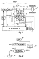
D'autres caractéristiques et avantages de la présente invention seront mieux compris à l'aide de la description et des figures annexées dans lesquelles :
- la
figure 1 est une vue schématique représentant les éléments principaux d'un véhicule dans lequel sont implémentés le procédé et le dispositif de l'invention ; - les
figures 2 et 3 sont des organigrammes pour exposer les divers aspects du procédé de l'invention ; - la
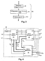
figure 4 est une vue schématique représentant les parties principales du dispositif de l'invention ; en mode tirage - la
figure 5 est une vue schématique représentant un mode particulier de réalisation du troisième bloc de lafigure 4 . - les
figures 6 illustrent le mode rétro- teset 7figures 8 illustrent le mode rampage en coupleet 9 - les
figures 10 et 11 illustrent le mode rampage en vitesse
- the
figure 1 is a schematic view showing the main elements of a vehicle in which the method and the device of the invention are implemented; - the
figures 2 and3 are flowcharts for explaining the various aspects of the method of the invention; - the
figure 4 is a schematic view showing the main parts of the device of the invention; in draw mode - the
figure 5 is a schematic view showing a particular embodiment of the third block of thefigure 4 . - the
Figures 6 and 7 illustrate the retro modeFigures 8 and 9 illustrate the couple rampage mode - the
Figures 10 and 11 illustrate the speed creep mode
Dans la suite du texte, les notations suivantes ont la signification suivante :
- Le terme â ou ^a désigne une estimation de la variable a ;
- Le terme a* ou le terme a* désigne une consigne optimisée de! a variable a ;
- Le terme a# ou le terme a# désigne une consigne calculée de la variable a ;
- Le terme a ou le terme a' désigne la variation temporelle de la variable a ;
- un arbre 16 pour échanger de la puissance mécanique avec les roues 6 du véhicule ;
- des arbres 17
et 18 pour échanger de la puissance mécanique avec les rotors des deux machines électriques 11et 12.
- The term? Or? A designates an estimate of the variable a;
- The term a * or the term a * designates an optimized setpoint of! a variable a;
- The term a # or the term a # designates a calculated setpoint of the variable a;
- The term a or the term a 'denotes the temporal variation of the variable a;
- a
shaft 16 for exchanging mechanical power with the wheels 6 of the vehicle; -
shafts electric machines
- a
Le moteur thermique 4 est contrôlé en couple par un contrôleur 3 et les machines électriques 11 et 12 sont respectivement contrôlées par un contrôleur 19 et par un contrôleur 20. La chaîne cinématique 13 de la transmission IVT 5 comporte ainsi qu'il est connu des coupleurs comme des embrayages et des freins qui sont commandés par un contrôleur de mode de transmission qui n'est ni décrit ni représenté dans la présente demande mais qui est défini dans les précédentes demandes de brevet précitées du demandeur.The
Le premier mode de fonctionnement du groupe motopropulseur GMP concerné par la présente invention est lemode tirage appelé Torque Tracking (TT), au cours duquel le moteur thermique fournit un couple positif à la transmission (tirage). Au cours de ce mode, les objectifs mécaniques poursuivis par le procédé de l'invention sont la régulation du régime du moteur thermique et du couple fourni aux roues. L'objectif énergétique poursuivi par le procédé de l'invention est la régulation de la tension du condensateur.The first mode of operation of the GMP powertrain concerned by the present invention is the draw method called Torque Tracking (TT), during which the engine provides a positive torque to the transmission (pull). During this mode, the mechanical objectives pursued by the method of the invention are the regulation of the engine speed and the torque supplied to the wheels. The energy objective pursued by the method of the invention is the regulation of the capacitor voltage.
Dans la suite de la description, on exploitera les grandeurs désignées par les notations :
- .we1 : régime de la première machine électrique 11,
- .we2 : régime de la seconde
machine électrique 12, - .Tde1 : couple de perturbation appliqué sur le couple fourni par la première
machine électrique M e1 11, - .Tde2 : couple de perturbation appliqué sur le couple fourni par la seconde
machine électrique M e2 12, - .Te1# : consigne de couple pour la première
machine électrique M e1 11, - . Te2# : consigne de couple pour la première
machine électrique M e2 12, - . wice : régime du moteur thermique ice 4,
- . Tice : couple du moteur thermique ice appliqué sur le vilebrequin 8,
- . Tdice : couple de perturbation appliqué sur le couple du moteur thermique 4,
- . Tice# : consigne de couple pour le moteur thermique 4,
- . To: couple appliqué aux roues par le groupe motopropulseur GMP,
- . Tdwh : couple de perturbation appliqué sur le couple aux roues,
- . W : niveau d'énergie du condensateur,
- . j(Te1, Te2, we1, we2) : cette fonction scalaire est définie par la puissance échangée par le condensateur 10 avec les machines électriques, ainsi que l'ensemble des pertes du variateur électrique comprenant les deux machines électriques Me1 et Me2 et leur condensateur de stockage,
- . PdW : puissance de perturbation appliquée sur la dynamique du condensateur.
- .w e1 : speed of the first
electric machine 11, - .w e2 : speed of the second
electric machine 12, - .Td e1 : disturbance torque applied to the torque supplied by the first
electrical machine M e1 11, - .Td e2 : disturbance torque applied to the torque supplied by the second
electric machine M e2 12, - .T e1 #: torque setpoint for the first
electrical machine M e1 11, - . T e2 #: torque setpoint for the first
electrical machine M e2 12, - . w ice :
engine speed ice 4, - . T ice : torque of the thermal engine ice applied on the
crankshaft 8, - . Td ice : disturbance torque applied to the torque of the
heat engine 4, - . T ice #: torque setpoint for the
heat engine 4, - . To: Torque applied to the wheels by the GMP powertrain,
- . T dwh : disturbance torque applied to the torque to the wheels,
- . W: energy level of the capacitor,
- . j (T e1 , T e2 , w e1 , w e2 ): this scalar function is defined by the power exchanged by the
capacitor 10 with the electrical machines, as well as all the losses of the electric variator comprising the two electrical machines M e1 and M e2 and their storage capacitor, - . PdW: disturbance power applied to the capacitor dynamics.
Les variables décrivant l'état du système sont divisées en deux listes unidimensionnelles ou vecteurs X1 et X2, ici représentées sous leur forme vectorielle transposée : ![]()
![]()
![]()
![]()
Le vecteur d'état X1 comporte :
- des valeurs de régime du variateur électrique ;
- des valeurs de couple moteur thermique ;
- des valeurs de perturbation des signaux de couple.
- speed values of the electric drive;
- thermal engine torque values;
- disturbance values of the torque signals.
Le vecteur d'état X2 comporte :
- au moins une valeur décrivant l'état énergétique de l'élément tampon d'énergie dans le variateur de vitesses ;
- au moins une valeur de perturbation de cet état énergétique.
- at least one value describing the energy state of the energy buffer element in the variator;
- at least one disturbance value of this energy state.
Le dispositif de commande 2 de l'invention reçoit un entrée un vecteur V de trois groupes de paramètres d'état du variateur électrique 21 qui sont :
- l'état de puissance électrique (Te1, We1) de la
machine électrique M e1 11par une ligne 22 issue du contrôleur 19 ; - l'état de puissance électrique (Te2, We2) de la
machine électrique M e2 12par une ligne 23 issue du contrôleur 20 ; - l'état de charge électrique (Ucapa) de l'élément tampon d'énergie 10.
- the electric power state (T e1 , W e1 ) of the
electric machine M e1 11 by aline 22 from the controller 19; - the state of electrical power (T e2 , W e2 ) of the
electrical machine M e2 12 by aline 23 from the controller 20; - the state of electric charge (Ucapa) of the
energy buffer element 10.
En réponse, et en appliquant le procédé de l'invention, le dispositif de commande 2 retourne des signaux de contrôle pour les actionneurs du groupe motopropulseur 1, à savoir :
- un signal de contrôle émis par une
ligne 7 à destination du contrôleur 3 du moteur thermique 4 qui permet d'atteindre un objectif de régulation sur le régime du moteur thermique ; - un signal de contrôle émis par des lignes 8
et 9 à destination des contrôleurs du variateur électrique 21 qui permet d'atteindre simultanément à l'objectif de régulation sur le régime du moteur thermique et un objectif de régulation de couple à la roue To.
- a control signal transmitted by a
line 7 to thecontroller 3 of theengine 4 which achieves a control objective on the engine speed; - a control signal emitted by
lines electric drive 21 which makes it possible to simultaneously reach the regulation objective on the engine speed and a torque control objective to the wheel To.
Dans un mode préféré de réalisation, le signal de contrôle émis par une ligne 7 est un signal de commande de couple Tice# du moteur thermique.In a preferred embodiment, the control signal emitted by a
Dans un mode préféré de réalisation, le signal de contrôle émis par des lignes 8 et 9 est une paire de signaux de commande de couple Te1# et Te2# respectivement transmis à des entrées convenables des contrôleurs 19 et 20 des machines électriques Me1 11 et Me2 12.In a preferred embodiment, the control signal emitted by
A la
Après une opération de début de commande lors d'une étape S1 au cours de laquelle le dispositif de commande de l'invention est configuré puis initialisé, et ultérieurement uniquement initialisé sauf lors d'opérations de maintenance, le contrôle passe à une étape S2 au cours de laquelle les commandes Tice#, Te1#, Te2# des trois actionneurs sont calculées sur la base d'un vecteur de mesure Z qui sera décrit ci-après. A cet effet, le procédé de l'invention a été représenté par une fonction f() prédéterminée, étant entendu que son expression est déterminée de manière analytique ou algorithmique sur la base des informations de la description en fonction des objectifs de la commande qui sont de calculer la commande des trois actionneurs disponibles - moteur thermique et machines électriques - permettant de réaliser le point de fonctionnement requis par les couches supérieures de supervision particulièrement dans le mode de tirage et en utilisant une méthode de suivi de couple (Torque Tracking).After a command start operation in a step S1 during which the control device of the invention is configured and initialized, and subsequently only initialized except during maintenance operations, the control passes to a step S2 in which the T ice #, T e1 #, T e2 # commands of the three actuators are calculated on the basis of a measurement vector Z which will be described below. For this purpose, the method of the invention has been represented by a predetermined function f (), it being understood that its expression is determined analytically or algorithmically on the basis of the information of the description as a function of the objectives of the control which are to calculate the control of the three actuators available - heat engine and electrical machines - to achieve the operating point required by the upper layers of supervision particularly in the draw mode and using a Torque Tracking method.
Une fois les valeurs calculées lors de l'étape S2, ces valeurs sont passées aux trois contrôleurs du groupe motopropulseur à savoir Tice pour le contrôleur du moteur thermique, Te1 pour le contrôleur de la première machine électrique et Te2 pour le contrôleur de la seconde machine électrique. Puis, le contrôle passe à une étape S3 de test de fin de mode d'entraînement spécifique. En effet, le procédé de l'invention peut être arrêté puis un autre mode d'entraînement sélectionné. Si le test S3 est négatif, le contrôle passe à une étape S4 de mesure des valeurs instantanées des variables passées ensuite en arguments à la fonction f() lors de son évaluation lors de l'étape S2 précitée. Les diverses mesures sont collationnées dans un vecteur Z, qui dans un mode préféré de réalisation de l'invention comporte :
- le niveau d'énergie stockée dans l'élément tampon d'énergie du variateur de la transmission infiniment variable, mesuré préférentiellement par la tension à ses bornes ;
- pour chacune des deux machines électriques du variateur le couple Te1 ou Te2 et la vitesse de rotation we1 ou we2.
- the level of energy stored in the energy buffer element of the infinitely variable transmission drive, preferably measured by the voltage at its terminals;
- for each of the two electrical machines of the variator the torque T e1 or T e2 and the rotation speed w e1 or w e2 .
Si le test S3 est négatif, le contrôle passe à une étape de fin au cours de laquelle le dispositif de commande de l'invention est désactivé.If the test S3 is negative, the control goes to an end step during which the control device of the invention is deactivated.
Dans un mode particulier de réalisation, le procédé de l'invention comporte les étapes suivantes :
- détermination du niveau de charge Ucapa du variateur 21, du couple à la roue To et du régime du moteur thermique vice,
- obtention de valeurs intermédiaires par régulation du niveau de charge, du couple à la roue et du régime moteur thermique déterminés en fonction de valeurs de consigne, et
- découplage des valeurs intermédiaires en signaux de commande Te1#, Te2# du variateur 21 et en signal de commande Tics# du moteur thermique 4.
- determination of the load level Ucapa of the
drive 21, the torque at the wheel To and the speed of the thermal engine vice, - obtaining intermediate values by regulating the load level, the torque at the wheel and the thermal engine speed determined according to set values, and
- decoupling the intermediate values into control signals T e1 #, T e2 # of the
variator 21 and control signal T ics # of theheat engine 4.
Dans un mode particulier de réalisation, le procédé de l'invention consiste à effectuer le découplage des signaux intermédiaires en exploitant des valeurs déterminées de :
- régimes (we1, we2) des machines électriques (Me1, 11 ; Me2, 12),
- régime (wice) du moteur thermique (4),
- couple appliqué (Tice) sur le vilebrequin du moteur thermique (4),
- couples électromagnétiques (Te1, Te2) des machines électriques (
M e1 11, Me2 12), - niveau de charge (Ucapa) du variateur électrique,
- facteurs de correction des échanges de puissance électrique dans le variateur,
- facteurs de correction des couples appliqués sur le vilebrequin et sur les roues.
- regimes (w e1 , w e2 ) of electrical machines (M e1 , 11, M e2 , 12),
- speed (w ice ) of the engine (4),
- torque applied (T ice ) on the crankshaft of the engine (4),
- electromagnetic couples (T e1 , T e2 ) of electrical machines (
M e1 11, M e2 12), - load level (Ucapa) of the electric drive,
- correction factors for the exchange of electrical power in the drive,
- torque correction factors applied to the crankshaft and to the wheels.
A la
Lors d'une étape S8, le procédé de l'invention consiste à effectuer une estimation du régime moteur thermique ^wice, du niveau d'énergie ^W, du couple à la roue ^To et d'un vecteur ^Xf rassemblant les grandeurs de simulation de la chaîne électromécanique représentant le variateur électrique de la transmission infiniment variable du groupe motopropulseur donné. Le vecteur ^Xf sera décrit et défini à l'aide de la
Une fois l'étape S8 de détermination effectuée, une étape de régulation S9 est effectuée sur la base des données estimées à l'étape S8 et sur la donnée de deux valeurs de consigne qui correspondent à une demande de point de fonctionnement du groupe motopropulseur. Dans un mode particulier de réalisation, adapté notamment à l'architecture à trois couches définie dans le procédé décrit dans la précédente publication
Une fois l'étape S9 de régulation effectuée, une étape de découplage S10 est effectuée sur la base des variables intermédiaires produites à l'étape S9. L'étape de découplage S10 produit le couple de valeurs de consigne à destination des contrôleurs du groupe motopropulseur, à savoir :
- une consigne de couple moteur Tice# ;
- une consigne de couple pour chacune des machines électriques respectivement Te1# et Te2# ;
- a motor torque setpoint T ice #;
- a torque setpoint for each of the electrical machines respectively T e1 # and T e2 #;
A la
La structure de commande mise en oeuvre dans le dispositif de commande 2 selon l'invention est basée sur la structure de commande multivariable à trois consignes présentée dans la publication
Le superviseur ou contrôleur OPF, qui exécute l'optimisation du point de fonctionnement du moteur thermique, fournit à l'entrée du contrôleur de troisième couche COS une consigne de régime du moteur thermique. Le superviseur ou contrôleur IVC fournit également une consigne du couple roue. On dispose par ailleurs d'une consigne de tension du condensateur qui sert le plus souvent d'élément tampon d'énergie pour le variateur électrique. A partir de ces trois consignes et des mesures disponibles décrivant l'environnement du véhicule, comme la vitesse du véhicule ou la pente dans laquelle il est engagé, le contrôleur COS génère les consignes de couple pour les trois principaux actionneurs du GMP, à savoir les deux machines électriques (Me1 et Me2) et le moteur thermique dans le mode « tirage » concerné par l'invention.The supervisor or controller OPF, which performs optimization of the operating point of the engine, provides the input of the third layer controller COS a speed reference of the engine. The IVC supervisor or controller also provides a torque setpoint. There is also a voltage setpoint of the capacitor which is most often used as an energy buffer element for the electric drive. From these three setpoints and available measurements describing the vehicle environment, such as the speed of the vehicle or the slope in which it is engaged, the COS controller generates the torque setpoints for the three main actuators of the GMP, namely the two electric machines (Me1 and Me2) and the heat engine in the "draw" mode concerned by the invention.
Dans une première couche, un module exécute une interprétation de la volonté du conducteur en fonction de la détection de l'environnement du véhicule, notamment de la vitesse de déplacement du véhicule. Particulièrement, on détecte que le degré d'enfoncement de la pédale d'accélérateur ou celui de la pédale de frein est nul pour déterminer qu'on est en mode « tirage ».In a first layer, a module performs an interpretation of the driver's will based on the detection of the vehicle environment, including the speed of movement of the vehicle. In particular, it is detected that the degree of depression of the accelerator pedal or that of the brake pedal is zero to determine that it is in "draw" mode.
A la
- une unité de détermination 36 des variables décrivant l'état du système,
- une unité de régulation 34 et
- une unité de découplage 35.
- a unit for determining 36 variables describing the state of the system,
- a
control unit 34 and - a
decoupling unit 35.
Le paramétrage de ces unités repose sur un modèle de comportement du véhicule, sous la forme d'un modèle de représentation au sens de l'Automatique, de conception suffisamment simple pour être directement exploitable, et suffisamment complexe pour traduire l'ensemble des phénomènes physiques pertinents. Son choix a été conduit sur la base de nombreuses déterminations théoriques d'une part et d'essais pratiques permettant d'atteindre les objectifs précités. Le modèle de conception précité est un modèle multi variable non linéaire.The configuration of these units is based on a model of vehicle behavior, in the form of a representation model in the sense of the Automatic, sufficiently simple design to be directly exploitable, and complex enough to translate all physical phenomena relevant. His choice was made on the basis of numerous theoretical determinations on the one hand and practical tests to achieve the aforementioned objectives. The aforementioned design model is a nonlinear multi variable model.
L'unité de détermination 36 comporte cinq portes d'entrée :
- une porte d'entrée a recevant le signal de consigne de couple de la première machine électrique Te1 # ;
- une porte d'entrée b recevant le signal de consigne de couple de la seconde machine électrique Te2 # ;
- une porte d'entrée c recevant le signal de consigne de couple du moteur thermique Tice # ;
- une porte d'entrée d recevant un vecteur caractérisant l'état électrique des machines électriques we1, we2, Te1, Te2 ;
- une porte d'entrée e recevant un signal de mesure de la tension aux bornes de la super capacité Ucapa.
- an input gate receiving the torque command signal from the first electrical machine T e1 #;
- an input gate b receiving the torque command signal of the second electrical machine T e2 #;
- an input gate c receiving the torque reference signal of the heat engine T ice #;
- an input gate d receiving a vector characterizing the electrical state of the electrical machines w e1 , w e2 , T e1 , T e2 ;
- an input gate e receiving a signal for measuring the voltage across the super capacitance Ucapa.
L'unité de détermination 36 comporte quatre portes de sortie qui sont :
- une porte de sortie S1 qui produit un signal d'estimation sous forme d'un vecteur ^Xf transmis à la porte d'entrée e de l'unité de découplage 35 ;
- une porte de sortie S2 qui produit un couple de valeurs d'estimation du régime moteur ^wice, et de sa dérivée temporelle ^w'ice, couple de valeurs qui est transmis respectivement à la porte d'entrée f de l'unité de régulation 34 et la porte d'entrée d de l'unité de découplage 35 ;
- une porte de sortie S3 qui produit un couple de valeurs d'estimation du niveau d'énergie de l'élément tampon d'énergie ^W et de sa variation temporelle ^W' qui est transmis à la porte d'entrée e de l'unité de régulation ;
- une porte de sortie S4 qui produit un signal d'estimation du couple moteur ^T0 qui est transmis à la porte d de l'unité de régulation 34.
- an output port S1 which produces an estimation signal in the form of a vector Xf transmitted to the input gate e of the
decoupling unit 35; - an output port S2 which produces a pair of engine speed estimation values ^ w ice , and its time derivative ^ w ' ice , a pair of values which is transmitted respectively to the input gate f of the transmission unit.
control 34 and the entrance door d of thedecoupling unit 35; - an output gate S3 which produces a pair of energy level estimation values of the energy buffer element W and its temporal variation W which is transmitted to the input gate e of the control unit;
- an output port S4 which produces a motor torque estimation signal T0 which is transmitted to the gate d of the
control unit 34.
L'unité de détermination 36 comporte un circuit de construction de ^Xf a pour rôle de construire le signal d'estimation ^Xf qui est représenté par le vecteur suivant qui comporte neuf composantes vectorielles : ![]()
![]()
L'estimation de ces signaux est calculée par un observateur linéaire construit à partir du modèle de conception choisi, par mise en oeuvre des techniques connues d'Automatique des Systèmes linéaires. On pourra se reporter aux ouvrages concernant la reconstructions d'état de tels systèmes et particulièrement à l'ouvrage de
Les gains de cet observateur constituent des paramètres de réglage de l'unité de détermination.The gains of this observer are adjustment parameters of the determination unit.
L'unité de régulation 34 comporte six portes d'entrée :
- une porte d'entrée a recevant un signal de consigne de la tension aux bornes du tampon en énergie 10 ;
- une porte d'entrée b recevant un signal de consigne du régime moteur wice * ;
- une porte d'entrée c recevant un signal de consigne du couple moteur To* ;
- une porte d'entrée d recevant un signal d'estimation du couple moteur ^To ;
- une porte d'entrée e recevant un signal d'estimation du niveau d'énergie ^W ou de sa variation ^W' ;
- une porte d'entrée f recevant un signal d'estimation du régime moteur ^wice et de sa variation ^w'ice.
- an input gate receiving a set signal of the voltage across the
energy buffer 10; - an entry door b receiving a motor speed setpoint signal w ice *;
- an input gate c receiving a target signal of the motor torque To *;
- an input gate receiving a signal estimating the engine torque To;
- an input gate e receiving a signal for estimating the energy level W W or its variation W W ';
- f a gateway receiving an estimation signal of the engine speed ^ w ice and its variation ^ w 'ice.
L'unité de régulation 34 comporte trois portes de sortie qui sont respectivement :
- une porte de sortie S1 de signal de commande intermédiaire v1 ;
- une porte de sortie S2 de signal de commande intermédiaire v2 ;
- une porte de sortie S3 de signal de commande intermédiaire v3.
- an intermediate control signal output port S1 v1;
- an intermediate control signal output port S2 v2;
- an intermediate control signal output port S3 v3.
A partir des trois consignes :
- de niveau d'énergie de l'élément tampon W* ;
- de régime du moteur thermique wice* ; et
- de couple aux roues To*,
- - le signal v1 est calculé par un circuit incorporant un régulateur de type proportionnel dérivé à partir de la consigne de charge de l'élément tampon d'énergie comme la tension aux bornes d'un condensateur 10 ;
- - le signal v2 est calculé par un circuit incorporant un régulateur de type proportionnel dérivé à partir de la consigne de régime thermique et de l'estimée du régime thermique ;
- - le signal v3 est calculé par un régulateur de type proportionnel à partir de la consigne de couple aux roues et de l'estimée du couple aux roues.
- energy level of the buffer element W *;
- engine speed w ice *; and
- torque to To * wheels,
- the signal v1 is calculated by a circuit incorporating a proportional type regulator derived from the load setpoint of the energy buffer element as the voltage across a
capacitor 10; - the
signal v 2 is calculated by a circuit incorporating a proportional type regulator derived from the thermal regime setpoint and the estimated thermal regime; - the signal v3 is calculated by a proportional type regulator from the torque setpoint to the wheels and from the estimated torque to the wheels.
L'unité de découplage 35 comporte cinq portes d'entrée :
- une porte d'entrée a recevant le signal de commande intermédiaire v1 issu de la sortie S1 de l'unité de régulation 34 ;
- une porte d'entrée b recevant le signal de commande intermédiaire v2 issu de la sortie S2 de l'unité de régulation 34 ;
- une porte d'entrée c recevant le signal de commande intermédiaire v3 issu de la sortie S3 de l'unité de régulation 34 ;
- une porte d'entrée d recevant un signal d'estimation du niveau d'énergie ^Wice ou de sa variation ^'Wice ;
- une porte d'entrée e recevant un signal d'estimation d'un vecteur de contrôle Xf.
- an input gate receiving the intermediate control signal v1 from the output S1 of the
control unit 34; - an input gate b receiving the intermediate control signal v2 from the output S2 of the
control unit 34; - an input gate c receiving the intermediate control signal v3 from the output S3 of the
control unit 34; - an input gate d receiving a signal for estimating the energy level W ice or its variation W ice ;
- an input gate e receiving an estimation signal of a control vector Xf.
L'unité de découplage 35 comporte trois portes de sortie qui sont respectivement :
- une porte de sortie S1 de consigne de couple de la première machine électrique Te1 # ;
- une porte de sortie S2 de consigne de couple de la seconde machine électrique Te2 # ;
- une porte de sortie S3 de consigne de couple du moteur thermique Tice #.
- an output port S1 of torque setpoint of the first electrical machine T e1 #;
- an output port S2 of torque setpoint of the second electrical machine T e2 #;
- an output port S3 of torque setpoint of the heat engine T ice #.
A partir des signaux de commande intermédiaires (v1, v2, v3) produits par l'unité de régulation 34 et à partir des estimés du vecteur ^Xf sur l'état du système fournies par l'unité de détermination 36, l'unité de découplage 35 construit les signaux de commande de couple moteur thermique Tice#, et des deux couples électromagnétiques Te1# et Te2# des machines électriques du variateur 21. L'étape concernée du procédé de l'invention comporte les sous étapes suivantes :
- une étape de découplage des signaux de commande intermédiaires (v1, v2, v3) basée sur l'inversion du modèle de conception par dérivations successives des sorties telle que cette méthode est exposée notamment dans l'ouvrage de
A. Isidori, « Non Linear Control Systems », 2d Edition, Springer-Verlag, 1989 - une étape d'intégration des deux premiers signaux intermédiaires (u1, u2) pour produire le signal de contrôle du couple à la roue sous la forme du doublet de commande des couples électromagnétiques (Te1#, Te2#) ;
- une étape de saturation du signal u3 par le couple thermique maximal dépendant du régime thermique, le signal de commande Tice# est déduit du signal u3 par un opérateur retard discret.
- a step of decoupling the intermediate control signals (v1, v2, v3) based on the inversion of the design model by successive derivations of the outputs as this method is exposed in particular in the book of
A. Isidori, "Non Linear Control Systems," 2d Edition, Springer-Verlag, 1989 - a step of integrating the two first intermediate signals (u1, u2) to produce the torque control signal to the wheel in the form of the control pair of the electromagnetic couples (T e1 #, T e2 #);
- a step of saturation of the signal u3 by the maximum thermal torque dependent on the thermal regime, the control signal T ice # is deduced from the signal u3 by a discrete delay operator.
À la
Les trois signaux de régulation V1, V2, V3 sont transmis à un rassembleur vectoriel 140 dont la sortie transmet en séquence des trois signaux à une première borne d'entrée d'un circuit 141 qui réalise l'inversion du modèle de conception par dérivations successives des sorties.The three regulation signals V 1 , V 2 , V 3 are transmitted to a
Le circuit 141 d'inversion du modèle comporte aussi une seconde borne d'entrée connectée à l'entrée e(35) qui reçoit le vecteur d'estimation ^Xf. De ce fait, l'inversion travaille à la fois sur les composantes de régulation V1, V2 et V3 et sur les composants du vecteur d'estimation ^Xf.The
Les trois signaux de sortie qui correspondent à l'inversion du modèle sont désignés respectivement par U1, U2 et U3 et sont transmis à un séparateur vectoriel 142 dont la première borne de sortie sélectionne la première paire de valeurs U1 et U2, qui sont fournies à l'entrée d'un circuit d'intégration 143 - 147, pour obtenir les deux signaux de commande (Te1#, Te2#) à destination des circuits de contrôle des machines électriques du variateur.The three output signals corresponding to the inversion of the model are denoted by U1, U2 and U3, respectively, and are transmitted to a
Dans ce mode particulier de réalisation, le circuit d'intégration comporte un gain 143 réglé avec une constante de temps Ts. Le signal de sortie du gain 143 qui a traité également les composantes U1 et U2, est transmis à une borne d'entrée d'un additionneur 144. La borne de sortie de l'additionneur 144 est connectée à une première borne d'entrée d'un circuit de saturation 146. Le vecteur d'estimation ^Xf est aussi fourni à une borne d'entrée d'un bloc de sélection des composantes 2 et 3, référencé 145 dont la borne de sortie est connectée directement à une seconde borne d'entrée du circuit de saturation 146. Il ressort de ce schéma que le circuit de saturation 146 travaille d'une part à partir de la valeur des composantes d'inversion U1 et U2, et d'autre part à partir des composantes d'estimation des vitesse de rotation des deux machines électriques ^we1 et ^we2·In this particular embodiment, the integration circuit comprises a
L'unité de découplage 35 comporte aussi un bloc 149 de sélection de composante 1 dont la borne d'entrée reçoit le couple de valeurs représentatives de l'estimation du régime moteur ^wice de l'estimation de sa variation temporelle ^w'ice.The
La borne de sortie du bloc de sélection 149 de composante transmet ainsi le signal d'estimation du régime moteur ^wice à une première borne d'entrée d'un circuit de saturation 148. Une seconde borne d'entrée du circuit de saturation 148 est connectée au séparateur vectoriel 142 pour recevoir le troisième signal du modèle U3. Le circuit de saturation 148 comporte des moyens pour réaliser la saturation signal de commande Tice qui détermine la commande du couple moteur.The output terminal of the
Pour permettre de respecter le séquence du procédé de l'invention, on connecte sur la borne de sortie du circuit 148 un circuit 150 qui ajoute un retard discret pour l'élaboration de la commande Tice# du couple moteur à la borne de sortie S3(35) de l'unité 35 de découplage.To enable the sequence of the method of the invention to be observed, a
D'une manière générale, l'unité de découplage 35 du dispositif de l'invention comporte :
- un rassembleur vectoriel 140 rassemblant des valeurs intermédiaires issues de la régulation du niveau de charge, du couple aux roues et du régime du moteur thermique déterminés ;
un module 141 de découplage non linéaire recevant la sortie du rassembleur 140 et l'ensemble des variables déterminées ;un module 143 appliquant aux deux premières sorties dumodule 141 un gain égal à la période d'échantillonnage Ts du système ;- un opérateur d'addition 144 ajoutant au signal de sortie du
module 143 le premier signal de sortie de ladite unité ; un circuit 145 appliquant à la sortie de l'opérateur 144 une saturation en fonction du couple électromagnétique maximal qui dépend des régimes déterminés à chaque machine électriqueun circuit 147 appliquant un retard au signal de sortie du circuit desaturation 146 de façon à produire des signaux de commande de couple Te1#, Te2# des deux machines électriques,un circuit 148 appliquant à la troisième sortie dumodule 141 une saturation en fonction du couple maximal du moteur thermique qui dépend du régime déterminé du moteur thermique, etun circuit 150 appliquant un retard au signal de sortie du circuit desaturation 148 de façon à produire un signal de commande Tice# du couple du moteur thermique.
- a
vector gatherer 140 gathering intermediate values from the regulation of the load level, the torque to the wheels and the engine speed determined; - a
nonlinear decoupling module 141 receiving the output of thegatherer 140 and the set of variables determined; - a
module 143 applying to the first two outputs of the module 141 a gain equal to the sampling period Ts of the system; - an
addition operator 144 adding to the output signal of themodule 143 the first output signal of said unit; - a
circuit 145 applying to the output of the operator 144 a saturation as a function of the maximum electromagnetic torque which depends on the speeds determined for each electrical machine - a
circuit 147 applying a delay to the output signal of thesaturation circuit 146 so as to produce torque command signals T e1 #, T e2 # of the two electrical machines, - a
circuit 148 applying to the third output of the module 141 a saturation as a function of the maximum torque of the heat engine which depends on the determined speed of the engine, and - a
circuit 150 applying a delay to the output signal of thesaturation circuit 148 so as to produce a control signal T ice # of the torque of the heat engine.
Dans un mode particulier de réalisation, le mode d'entraînement spécifique exécuté par le procédé de l'invention assure la régulation de ralenti du moteur thermique tout en contrôlant le couple (To) fourni par le groupe motopropulseur.In a particular embodiment, the specific drive mode executed by the method of the invention provides the idle control of the engine while controlling the torque (To) provided by the powertrain.
En mode « rétro », le moteur thermique se trouve dans un mode de fonctionnement en coupure d'injection sous le contrôle d'un contrôleur indépendant du dispositif de commande proprement dit de l'invention. Quand un tel état d'entraînement est alors détecté, le dispositif de commande 2 laisse le contrôle du moteur thermique à un contrôleur 26 autonome de régime de coupure d'injection. Le contrôleur 26 de coupure d'injection est lui-même connecté par une ligne spécifique à une entrée correspondante de contrôle de ralenti sur le contrôleur 3 du moteur thermique 4. Dans le même temps, le dispositif de commande 2 de l'invention exécute le contrôle de son objectif de régulation du régime du moteur thermique en produisant des signaux de consigne Te1# et Te2# qui permettent ainsi de poursuivre les objectifs de régulation de la charge électrique de l'élément tampon 10.In "retro" mode, the heat engine is in a mode of operation in injection cut under the control of a controller independent of the control device itself of the invention. When such a training state is then detected, the
Après une opération de début de commande lors d'une étape S1 au cours de laquelle le dispositif de commande de l'invention est configuré puis initialisé, et ultérieurement uniquement initialisé sauf lors d'opérations de maintenance, le contrôle passe à une étape S2 au cours de laquelle les commandes Te1#, Te2# des deux actionneurs sont calculées sur la base d'un vecteur de mesure Z qui sera décrit ci-après. A cet effet, le procédé de l'invention a été représenté par une fonction fretro() prédéterminée, étant entendu que son expression est déterminée de manière analytique ou algorithmique sur la base des informations de la description en fonction des objectifs de la commande qui sont de calculer la commande des deux actionneurs disponibles sur les machines électriques et permettant de réaliser le point de fonctionnement requis par les couches supérieures de supervision particulièrement dans le mode d'entraînement « rétro ».After a command start operation in a step S1 in which the control device of the invention is configured and then initialized, and subsequently only initialized except during maintenance operations, the control goes to a step S2 at during which the orders T e1 #, T e2 # of the two actuators are calculated on the basis of a measurement vector Z which will be described below. For this purpose, the method of the invention has been represented by a predetermined function f retro (), it being understood that its expression is determined analytically or algorithmically on the basis of the information of the description as a function of the objectives of the command which are to calculate the control of the two actuators available on the electrical machines and to achieve the operating point required by the upper layers of supervision particularly in the "retro" drive mode.
Une fois le couple de valeurs calculé lors de l'étape S2, ces valeurs sont passées aux deux contrôleurs du groupe motopropulseur à savoir Te1 pour le contrôleur de la première machine électrique et Te2 pour le contrôleur de la seconde machine électrique. Puis, le contrôle passe à une étape S3 de test de fin de mode d'entraînement spécifique. En effet, le procédé de l'invention peut être arrêté puis un autre mode d'entraînement sélectionné. Si le test S3 est négatif, le contrôle passe à une étape S4 de mesure des valeurs instantanées des variables passées ensuite en arguments à la fonction f() lors de son évaluation lors de l'étape S2 précitée. Les diverses mesures sont collationnées dans un vecteur Z, qui dans un mode préféré de réalisation de l'invention comporte :
- le niveau d'énergie stockée dans l'élément tampon d'énergie du variateur de la transmission infiniment variable, mesuré préférentiellement par la tension à ses bornes ;
- the level of energy stored in the energy buffer element of the infinitely variable transmission drive, preferably measured by the voltage at its terminals;
Si le test S3 est négatif, le contrôle passe à une étape de fin au cours de laquelle le dispositif de commande de l'invention est désactivé.If the test S3 is negative, the control goes to an end step during which the control device of the invention is deactivated.
En mode rétro, le procédé de l'invention comporte les étapes suivantes :
- détermination du niveau de charge du variateur (21) et du régime (wice) du moteur thermique,
- obtention de valeurs intermédiaires par régulation du niveau de charge et du régime du moteur thermique déterminés en fonction de valeurs de consignes et
- determination of the load level of the inverter (21) and the speed (w ice ) of the heat engine,
- obtaining intermediate values by regulating the load level and the speed of the thermal engine determined according to setpoint values and
Dans un mode particulier de réalisation, le procédé de l'invention consiste à effectuer le découplage des signaux intermédiaires en exploitant des valeurs déterminées de :
- régimes des machines électriques,
- couple appliqué sur le vilebrequin du moteur thermique,
- couples électromagnétiques des machines électriques,
- niveau de charge du variateur,
- facteurs de correction des échanges de puissances électriques dans le variateur,
- regimes of electrical machines,
- torque applied to the crankshaft of the engine,
- electromagnetic couples of electrical machines,
- load level of the drive,
- correction factors for exchanges of electrical powers in the drive,
Lors d'une étape S8, le procédé de l'invention consiste à effectuer une estimation du régime moteur thermique ^wice, du niveau d'énergie ^W, et d'un vecteur ^Xf rassemblant les grandeurs de simulation de la chaîne électromécanique représentant le variateur électrique de la transmission infiniment variable du groupe motopropulseur donné. Le vecteur ^Xf sera décrit et défini à l'aide de la
Une fois l'étape S8 de détermination effectuée, une étape de régulation S9 est effectuée sur la base des données estimées à l'étape S8 et sur la donnée d'une valeur de consigne qui correspond à une demande de point de fonctionnement du groupe motopropulseur. Dans un mode particulier de réalisation, adapté notamment à l'architecture à trois couches définie dans le Procédé décrit dans la précédente publication
Une fois l'étape S9 de régulation effectuée, une étape de découplage S10 est effectuée sur la base des variables intermédiaires produites à l'étape S9. L'étape de découplage S10 produit le couple de valeurs de consigne à destination des contrôleurs du groupe motopropulseur sous la dépendance du dispositif de commande 2 de l'invention, à savoir une consigne de couple pour chacune des machines électriques respectivement Te1# et Te2# ; de sorte que le point de fonctionnement régulé du groupe motopropulseur (wice) soit atteint. L'algorithme de découplage sera défini ci-après.Once the control step S9 has been performed, a decoupling step S10 is performed on the basis of the intermediate variables produced in step S9. The decoupling step S10 produces the pair of setpoint values for the powertrain controllers under the
A la
La structure de commande mise en oeuvre dans le dispositif de commande 2 selon l'invention est basée sur la structure de commande multivariable à trois consignes présentée dans la publication
Le superviseur ou contrôleur OPF qui exécute l'optimisation du point de fonctionnement du moteur thermique fournit à l'entrée du contrôleur de troisième couche COS une consigne de régime du moteur thermique. On dispose par ailleurs d'une consigne de tension du condensateur qui sert le plus souvent d'élément tampon d'énergie pour le variateur électrique. A partir de ces deux consignes et des mesures disponibles décrivant l'environnement du véhicule, comme la vitesse du véhicule ou la pente dans laquelle il est engagé, le contrôleur COS génère les consignes de couple pour les deux principaux actionneurs du GMP, à savoir les deux machines électriques (Me1 et Me2) dans le mode « rétro ».The supervisor or OPF controller that performs the optimization of the operating point of the engine provides the input of the third layer controller COS a speed reference of the engine. There is also a voltage setpoint of the capacitor which is most often used as an energy buffer element for the electric drive. From these two instructions and available measurements describing the environment of the vehicle, such as the speed of the vehicle or the slope in which it is engaged, the COS controller generates the torque instructions for the two main actuators of the GMP, namely the two electric machines (Me1 and Me2) in the "retro" mode.
Dans une première couche, un module exécute une interprétation de la volonté du conducteur en fonction de la détection de l'environnement du véhicule, notamment de la vitesse de déplacement du véhicule. Particulièrement, on détecte que le degré d'enfoncement de la pédale d'accélérateur et celui de la pédale de frein sont nuls pour déterminer qu'on est en mode « rétro ».In a first layer, a module performs an interpretation of the driver's will based on the detection of the vehicle environment, including the speed of movement of the vehicle. In particular, it is detected that the degree of depression of the accelerator pedal and that of the brake pedal are zero to determine that is in "retro" mode.
A la
- une unité de détermination 36 des variables décrivant l'état du système,
- une unité de régulation 34, et
- une unité de découplage 35.
- a unit for determining 36 variables describing the state of the system,
- a
control unit 34, and - a
decoupling unit 35.
Le paramétrage de ces unités repose sur un modèle de comportement du véhicule, sous la forme d'un modèle de représentation au sens de l'Automatique, de conception suffisamment simple pour être directement exploitable, et suffisamment complexe pour traduire l'ensemble des phénomènes physiques pertinents. Son choix a été conduit sur la base de nombreuses déterminations théoriques d'une part et d'essais pratiques permettant d'atteindre les objectifs précités, d'autre part. Le modèle de conception précité est un modèle multi variable non linéaire.The configuration of these units is based on a model of vehicle behavior, in the form of a representation model in the sense of the Automatic, sufficiently simple design to be directly exploitable, and complex enough to translate all physical phenomena relevant. His choice was made on the basis of many theoretical determinations on the one hand and practical tests to achieve the above objectives, on the other hand. The aforementioned design model is a nonlinear multi variable model.
L'unité de détermination 36 comporte quatre portes d'entrée :
- Une porte d'entrée a recevant le signal de consigne de couple de la première machine électrique Te1 # ;
- Une porte d'entrée b recevant le signal de consigne de couple de la second machine électrique Te2 # ;
- Une porte d'entrée d recevant un vecteur caractérisant l'état électrique des machines électriques we1, we2, Te1, Te2 ;
- Une porte d'entrée e recevant un signal de mesure de la tension aux bornes de la super capacité Ucapa.
- An input gate receiving the torque command signal from the first electrical machine T e1 #;
- An input gate b receiving the torque command signal from the second electrical machine T e2 #;
- An input gate d receiving a vector characterizing the electrical state of electrical machines w e1 , w e2 , T e1 , T e2 ;
- An input gate e receiving a signal for measuring the voltage across the super capacitance Ucapa.
L'unité de détermination 36 comporte trois portes de sortie qui sont :
- Une porte de sortie S1 qui produit un signal d'estimation sous forme d'un vecteur ^Xf transmis à la porte d'entrée e de l'unité de découplage 35 ;
- Une porte de sortie S2 qui produit une valeur d'estimation du régime moteur ^wice, transmis à la porte d'entrée f de l'unité de régulation 34 ;
- Une porte de sortie S3 qui produit une valeur d'estimation du niveau d'énergie de l'élément tampon d'énergie ^W qui est transmis à la porte d'entrée e de l'unité de régulation.
- An output port S1 which produces an estimation signal in the form of a vector Xf transmitted to the input gate e of the
decoupling unit 35; - An output port S2 which produces an engine speed estimate value w w ice , transmitted to the input gate f of the
control unit 34; - An output gate S3 which produces an energy level estimation value of the energy buffer element W which is transmitted to the input gate e of the control unit.
L'unité de détermination 36 comporte une unité de construction de ^Xf qui a pour rôle de construire le signal d'estimation ^Xf qui est représenté par le vecteur suivant qui comporte neuf composantes vectorielles : ![]()
L'estimation de ces signaux est calculée par un observateur linéaire construit à partir du modèle de conception choisi, par mise en oeuvre des techniques connues d'Automatique des Systèmes linéaires. On pourra se reporter aux ouvrages concernant la reconstructions d'état de tels systèmes et particulièrement à l'ouvrage de ![]()
The estimation of these signals is calculated by a linear observer constructed from the chosen design model, by using the known techniques of Automatic Linear Systems. Reference can be made to the books concerning the state reconstructions of such systems and particularly to the work of
Les gains de cet observateur constituent des paramètres de réglage de l'unité de détermination.The gains of this observer are adjustment parameters of the determination unit.
L'unité de régulation 34 comporte quatre portes d'entrée :
- Une porte d'entrée a recevant un signal de consigne de la tension aux bornes du tampon en énergie 10 ;
- Une porte d'entrée b recevant un signal de consigne du régime moteur wice * ;
- Une porte d'entrée e recevant un signal d'estimation du niveau d'énergie de l'élément tampon d'énergie ^W ;
- Une porte d'entrée f recevant un signal d'estimation du régime moteur ^wice.
- An input gate receiving a voltage setpoint signal at the terminals of the
energy buffer 10; - An entry door b receiving a command signal of the engine speed w ice *;
- An input gate e receiving a signal for estimating the energy level of the energy buffer element W;
- F a gateway receiving an estimation signal of the motor ^ w ice regime.
L'unité de régulation 34 comporte deux portes de sortie qui sont respectivement :
- Une porte de sortie S1 de signal de commande intermédiaire v1 ;
- Une porte de sortie S2 de signal de commande intermédiaire v2.
- An intermediate control signal output port S1 v1;
- An intermediate control signal output port S2 v2.
L'unité de régulation 34 comporte deux unités de calcul respectivement du premier signal de commande intermédiaire v1 et du second signal de commande intermédiaire v2.The
L'unité de calcul du premier signal de commande intermédiaire v1 exécute à chaque cycle de calcul le calcul d'un régulateur de type proportionnel à partir de la consigne de charge de l'élément tampon d'énergie comme la tension aux bornes d'un condensateur 10.The calculation unit of the first intermediate control signal v1 performs, at each calculation cycle, the calculation of a proportional type regulator from the load reference of the energy buffer element as the voltage at the terminals of a
L'unité de calcul du second signal de commande intermédiaire v2 exécute à chaque cycle de calcul le calcul d'un régulateur de type proportionnel dérivé à partir de la consigne de régime thermique et de l'estimée du régime thermiqueThe calculation unit of the second intermediate control signal v2 executes, at each calculation cycle, the calculation of a proportional type regulator derived from the thermal regime reference and the thermal regime estimate.
L'unité de découplage 35 comporte trois portes d'entrée :
- Une porte d'entrée a recevant le signal de commande intermédiaire v1 issu de la sortie S1 de l'unité de régulation 34;
- Une porte d'entrée b recevant le signal de commande intermédiaire v2 issu de la sortie S1 de l'unité de régulation 34;
- une porte d'entrée e recevant un signal d'estimation d'un vecteur de contrôle Xf.
- An input gate receiving the intermediate control signal v1 from the output S1 of the
control unit 34; - An input gate b receiving the intermediate control signal v2 from the output S1 of the
control unit 34; - an input gate e receiving an estimation signal of a control vector Xf.
L'unité de découplage 35 comporte deux portes de sortie qui sont respectivement :
- Une porte de sortie S1 de consigne de couple de la première machine électrique Te1# ;
- Une porte de sortie S2 de consigne de couple de la seconde machine électrique Te2#.
- An output port S1 of torque setpoint of the first electrical machine T e1 #;
- An output port S2 torque setpoint of the second electrical machine T e2 #.
A partir des signaux de commande intermédiaire (v1, v2) produits par l'unité de régulation 34 et à partir des estimés du vecteur ^Xf sur l'état du système fournies par l'unité de détermination 36, l'unité de découplage 35 construit les signaux de commande de des deux couples électromagnétiques Te1# et Te2# des machines électriques du variateur 21. L'étape concernée du procédé de l'invention comporte les sous étapes suivantes :
- une étape de découplage des signaux de commande intermédiaires (v1, v2) basée sur l'inversion du modèle de conception par dérivations successives des sorties telle que cette méthode est exposée notamment dans l'ouvrage de A. Isidori, « Non Linear Control Systems », 2d Edition, Springer-Verlag, 1989, pour produire un doublet de commandes intermédiaires (u1, u2) ;
- une étape d'intégration des deux signaux intermédiaires (u1, u2) pour produire les commandes des couples électromagnétiques (Te1#, Te2#).
- a step of decoupling the intermediate control signals (v1, v2) based on the inversion of the design model by successive derivations of the outputs as this method is exposed in particular in the book by A. Isidori, "Non Linear Control Systems" , 2d Edition, Springer-Verlag, 1989, to produce a pair of intermediate commands (u1, u2);
- a step of integrating the two intermediate signals (u1, u2) to produce the commands of the electromagnetic couples (T e1 #, T e2 #).
À la
Les deux signaux de régulation V1, V2 sont transmis à un rassembleur vectoriel 140 dont la sortie transmet en séquence des trois signaux à une première borne d'entrée d'un circuit 141 qui réalise l'inversion du modèle de conception par dérivations successives des sorties. On se reportera notamment à l'ouvrage de A. Isidori , «Non Linear Control SYSTEMS» Springer-Verlag 1989.The two regulation signals V1, V2 are transmitted to a
Le circuit 141 d'inversion du modèle comporte aussi une seconde borne d'entrée connectée à l'entrée e(35) qui reçoit le vecteur d'estimation ^Xf. De ce fait, l'inversion travaille à la fois sur les composantes de régulation V1, V2 et sur les composants du vecteur d'estimation ^Xf.The
Les deux signaux de sortie qui correspondent à l'inversion du modèle sont désignés respectivement par u1, u2. Ils sont fournis à l'entrée d'un circuit d'intégration 143 - 147, pour obtenir les deux signaux de commande (Te1 #, Te2#) à destination des circuits de contrôle des machines électriques du variateur.The two output signals that correspond to the inversion of the model are designated u1, u2, respectively. They are supplied at the input of an integration circuit 143-147, to obtain the two control signals (Te1 #, Te2 #) for the control circuits of the electrical machines of the variator.
Dans ce mode particulier de réalisation, le circuit d'intégration comporte un intégrateur 143 réglé avec une constante de temps Ts. Le signal de sortie de l'intégrateur 143 qui a traité également les composantes U1 et U2, est transmis à une borne d'entrée d'un additionneur 144. La borne de sortie de l'additionneur 144 est connectée à une première borne d'entrée d'un circuit de saturation 146. Le vecteur d'estimation ^Xf est aussi fourni à une borne d'entrée d'un bloc de sélection des composantes 2 et 3, référencé 145 dont la borne de sortie est connectée directement à une seconde borne d'entrée du circuit de saturation 146. Il ressort de ce schéma que le circuit de saturation 146 travaille d'une part à partir de la valeur des composantes d'inversion U1 et U2, et d'autre part à partir des composantes d'estimation des vitesse de rotation des deux machines électriques ^we1 et ^we2.In this particular embodiment, the integration circuit includes an
En mode rampage en couple, le dispositif de commande 2 retourne des signaux de contrôle pour les actionneurs du groupe motopropulseur 1, à savoir :
- un signal de contrôle émis par une
ligne 25 pour mettre en service un contrôleur de ralenti 26 lorsque le dispositif de commande 2 place le véhicule dans le mode d'entraînement spécifique dit de rampage en couple et qui est lui-même connecté au contrôleur 3 du moteur thermique 4 ; - un signal de contrôle émis par des lignes 8
et 9 à destination des contrôleurs du variateur électrique 21 qui permet d'atteindre simultanément l'objectif de régulation sur le régime du moteur thermique et un objectif de régulation de couple à la roue To.
- a control signal emitted by a
line 25 to activate an idlingcontroller 26 when thecontrol device 2 places the vehicle in the specific drive mode called torque ramping and which is itself connected to thecontroller 3 of theheat engine 4; - a control signal emitted by
lines electric drive 21 which makes it possible to simultaneously achieve the regulation objective on the engine speed and a torque control objective to the wheel To.
Dans un mode préféré de réalisation, le signal de contrôle émis par des lignes 8 et 9 est une paire de signaux de commande de couple Te1# et Te2# respectivement transmis à des entrées convenables des contrôleurs 19 et 20 des machines électriques Me1 11 et Me2 12.In a preferred embodiment, the control signal transmitted by
Le dispositif de commande 2 de l'invention coopère avec un moyen permettant de modéliser le couple moteur produit par la combustion en mode de ralenti sous la forme d'une fonction Ttice et une partie de gestion du vilebrequin permettant de modéliser la transformation de l'énergie de combustion en énergie mécanique de rotation. La fonction Ttice dont l'expression dépend du véhicule modélisé, produit, à chaque instant défini par le séquenceur du dispositif de l'invention, des signaux ou valeurs numériques représentatifs d'un couple moteur thermique Tice et d'une vitesse de rotation ou régime du moteur thermique wice.The
Après une opération de début dé commande lors d'une étape S1 au cours de laquelle le dispositif de commande de l'invention est configuré puis initialisé, et ultérieurement uniquement initialisé sauf lors d'opérations de maintenance, le contrôle passe à une étape S2 au cours de laquelle les commandes Te1#, Te2# des deux actionneurs sont calculées sur la base d'un vecteur de mesure Z qui sera décrit ci-après. A cet effet, le procédé de l'invention a été représenté par une fonction f() et par une fonction fral() prédéterminées. Les deux fonctions sont déterminées de manière analytique ou algorithmique sur la base des informations de la description en fonction des objectifs de la commande qui sont de calculer la commande des deux actionneurs disponibles sur les machines électriques et de réaliser le point de fonctionnement requis par les couches supérieures de supervision particulièrement dans le mode d'entraînement « rampage en couple » selon la relation (Te1#, Te2#) = f(Z), tandis que le contrôleur de ralenti applique un contrôle représenté par la relation wice# = fral.(), fonction dans laquelle les arguments sont connus de l'homme de métier pour permettre la gestion du régime de ralenti.After a command start operation in a step S1 in which the control device of the invention is configured and then initialized, and subsequently only initialized except during maintenance operations, the control goes to a step S2 at during which the orders T e1 #, T e2 # of the two actuators are calculated on the basis of a measurement vector Z which will be described below. For this purpose, the method of the invention has been represented by a function f () and a function f ral () predetermined. The two functions are determined analytically or algorithmically on the basis of the information of the description according to the objectives of the control which are to calculate the control of the two actuators available on the electrical machines and to achieve the operating point required by the layers supervision superiors especially in the "torque ramping" training mode according to the relation (T e1 #, T e2 #) = f (Z), while the idle controller applies a control represented by the relation w ice # = f ral . (), a function in which the arguments are known to those skilled in the art to enable the management of the idle speed.
Une fois le couple de valeurs calculé lors de l'étape S2, ces valeurs sont passées aux trois contrôleurs du groupe motopropulseur à savoir une valeur de contrôle de régime de ralenti pour le contrôleur 26 du moteur thermique, Te1 pour le contrôleur de la première machine électrique et Te2 pour le contrôleur de la seconde machine électrique. Puis, le contrôle passe à une étape S3 de test de fin de mode d'entraînement spécifique. En effet, le procédé de l'invention peut être arrêté puis un autre mode d'entraînement sélectionné. Si le test S3 est négatif, le contrôle passe à une étape S4 de mesure des valeurs instantanées des variables passées ensuite en arguments à la fonction f() lors de son évaluation lors de l'étape S2 précitée. Les diverses mesures sont collationnées dans un vecteur Z, qui dans un mode préféré de réalisation de l'invention comporte :
- le niveau d'énergie stockée dans l'élément tampon d'énergie du variateur de la transmission infiniment variable, mesuré préférentiellement par la tension à ses bornes ;
- pour chacune des deux machines électriques du variateur le couple Te1 ou Te2 et la vitesse de rotation we1 ou we2.
- the level of energy stored in the energy buffer element of the infinitely variable transmission drive, preferably measured by the voltage at its terminals;
- for each of the two electrical machines of the variator the torque T e1 or T e2 and the rotation speed w e1 or w e2 .
Si le test S3 est négatif, le contrôle passe à une étape de fin au cours de laquelle le dispositif de commande de l'invention est désactivé.If the test S3 is negative, the control goes to an end step during which the control device of the invention is deactivated.
Dans un mode particulier de réalisation, le mode d'entraînement spécifique commandé dans le procédé de l'invention permet d'annuler le couple fourni par le groupe motopropulseur en dissipant l'énergie fournie par le moteur thermique.In a particular embodiment, the specific drive mode controlled in the method of the invention makes it possible to cancel the torque supplied by the powertrain by dissipating the energy supplied by the heat engine.
Dans un mode particulier de réalisation, le procédé de l'invention comporte les étapes suivantes :
- détermination du niveau de charge du variateur et du couple à la roue,
- obtention de valeurs intermédiaires par régulation du niveau de charge et du couple à la roue déterminés, en fonction de valeurs de consigne, et
- découplage des valeurs intermédiaires en signaux de commande du variateur électrique.
- determination of the load level of the drive and the torque at the wheel,
- obtaining intermediate values by regulating the determined load level and torque at the wheel, as a function of set values, and
- decoupling intermediate values into control signals of the electric drive.
Dans un mode particulier de réalisation, le procédé de commande de l'invention consiste à effectuer le découplage des signaux intermédiaires en exploitant des valeurs déterminées de :
- régimes des machines électriques ;
- couple appliqué sur le vilebrequin du moteur thermique ;
- couples électromagnétiques des machines électriques ;
- niveau de charge du variateur électrique ;
- facteurs de correction des échanges de puissance électriques dans le variateur 21 ;
- facteurs de correction des couples appliqués sur le vilebrequin et sur les roues.
- diets of electrical machines;
- torque applied to the crankshaft of the engine;
- electromagnetic couples of electrical machines;
- load level of the electric drive;
- correction factors for electrical power exchanges in the
drive 21; - torque correction factors applied to the crankshaft and to the wheels.
Lors d'une étape S8, le procédé de l'invention consiste à effectuer une estimation du niveau d'énergie ^W, du couple à la roue ^To et d'un vecteur ^Xf rassemblant les grandeurs de simulation de la chaîne électromécanique représentant le variateur électrique de la transmission infiniment variable du groupe motopropulseur donné. Le vecteur ^Xf sera décrit et défini à l'aide de la
Une fois l'étape S8 de détermination effectuée, une étape de régulation S9 est effectuée sur la base des données estimées à l'étape S8 et sur la donnée d'une valeur de consigne qui correspond à une demande de point de fonctionnement du groupe motopropulseur. Dans un mode particulier de réalisation, adapté notamment à l'architecture à trois couches définie dans le procédé décrit dans la précédente publication
Une fois l'étape S9 de régulation effectuée, une étape de découplage S10 est effectuée sur la base des variables intermédiaires produites à l'étape S9. L'étape de découplage S10 produit le couple de valeurs de consigne à destination des contrôleurs du groupe motopropulseur sous la dépendance du dispositif de commande 2 de l'invention, à savoir une consigne de couple pour chacune des machines électriques respectivement Te1# et Te2#, de sorte que le point de fonctionnement régulé du groupe motopropulseur (To) soit atteint. L'algorithme de découplage sera défini ci-après.Once the control step S9 has been performed, a decoupling step S10 is performed on the basis of the intermediate variables produced in step S9. The decoupling step S10 produces the pair of setpoint values for the powertrain controllers under the
A la
En mode rampage de couple, on construit une couche intermédiaire de commande (COS) où le moteur thermique n'est pas commandé par les deux couches supérieures, mais travaille en régime de ralenti sans être découplé de la transmission infiniment variable.In torque ramping mode, an intermediate control layer (COS) is built where the heat engine is not controlled by the two upper layers, but works in idle mode without being decoupled from the infinitely variable transmission.
Le superviseur ou contrôleur IVC fournit à l'entrée du contrôleur de troisième couche COS une consigne de couple roue. On dispose par ailleurs d'une consigne de tension du condensateur qui sert le plus souvent d'élément tampon d'énergie pour le variateur électrique. A partir de ces deux consignes et des mesures disponibles décrivant l'environnement du véhicule, comme la vitesse du véhicule ou la pente dans laquelle il est engagé, le contrôleur COS génère les consignes de couple pour les deux principaux actionneurs du GMP, à savoir les deux machines électriques (Me1 et Me2) dans le mode « rampage en couple » concerné par l'invention.The supervisor or controller IVC provides the input of the third layer controller COS a set torque wheel. There is also a voltage setpoint of the capacitor which is most often used as an energy buffer element for the electric drive. From these two instructions and available measurements describing the environment of the vehicle, such as the speed of the vehicle or the slope in which it is engaged, the COS controller generates the torque instructions for the two main actuators of the GMP, namely the two electric machines (Me1 and Me2) in the "torque ramping" mode of the invention.
Dans une première couche, un module exécute une interprétation de la volonté du conducteur en fonction de la détection de l'environnement du véhicule, notamment de la vitesse de déplacement du véhicule. Particulièrement, on détecte que le degré d'enfoncement de la pédale d'accélérateur est nul et que celui de la pédale de frein n'est pas nul pour déterminer qu'on est en mode « rampage en couple ».In a first layer, a module performs an interpretation of the driver's will based on the detection of the vehicle environment, including the speed of movement of the vehicle. In particular, it is detected that the degree of depression of the accelerator pedal is zero and that of the brake pedal is not zero to determine that is in "torque ramping" mode.
A la
- une unité de détermination 36 des variables décrivant l'état du système,
- une unité de régulation 34, et
- une unité de découplage 35.
- a unit for determining 36 variables describing the state of the system,
- a
control unit 34, and - a
decoupling unit 35.
Le paramétrage de ces unités repose sur un modèle de comportement du véhicule, de conception suffisamment simple pour être directement exploitable, et suffisamment complexe pour traduire l'ensemble des phénomènes physiques pertinents. Son choix a été conduit sur la base de nombreuses déterminations théoriques d'une part et d'essais pratiques permettant d'atteindre les objectifs précités. Le modèle de conception précité est un modèle de conception multi variable non linéaire.The parameterization of these units is based on a model of vehicle behavior, sufficiently simple in design to be directly exploitable, and complex enough to translate all the relevant physical phenomena. His choice was made on the basis of numerous theoretical determinations on the one hand and practical tests to achieve the aforementioned objectives. The aforementioned design model is a nonlinear multi-variable design model.
L'unité de détermination 36 comporte quatre portes d'entrée :
- Une porte d'entrée a recevant le signal de consigne de couple de la première machine électrique Te1 # ;
- Une porte d'entrée b recevant le signal de consigne de couple de la seconde machine électrique Te2 # ;
- Une porte d'entrée d recevant un vecteur caractérisant l'état électrique des machines électriques we1, we2, Te1, Te2 ;
- Une porte d'entrée e recevant un signal de mesure de la tension aux bornes de la super capacité Ucapa.
- An input gate receiving the torque command signal from the first electrical machine T e1 # ;
- An input gate b receiving the torque command signal from the second electrical machine T e2 # ;
- An input gate d receiving a vector characterizing the electrical state of electrical machines w e1 , w e2 , T e1 , T e2 ;
- An input gate e receiving a signal for measuring the voltage across the super capacitance U capa .
L'unité de détermination 36 comporte trois portes de sortie qui sont :
- Une porte de sortie S1 qui produit un signal d'estimation sous forme d'un vecteur ^Xf transmis à la porte d'entrée e de l'unité de découplage 35 ;
- Une porte de sortie S4 qui produit une valeur d'estimation du couple à la roue ^To, transmise à la porte d'entrée d de l'unité de régulation 34 ;
- Une porte de sortie S3 qui produit une valeur d'estimation du niveau d'énergie de l'élément tampon d'énergie ^W qui est transmis à la porte d'entrée e de l'unité de régulation.
- An output port S1 which produces an estimation signal in the form of a vector Xf transmitted to the input gate e of the
decoupling unit 35; - An output gate S4 which produces a torque estimation value at the wheel T o , transmitted to the input gate d of the
control unit 34; - An output gate S3 which produces an energy level estimation value of the energy buffer element W which is transmitted to the input gate e of the control unit.
L'unité de détermination 36 comporte une unité de construction de l'estimation ^Xf qui a pour rôle de construire le signal d'estimation ^Xf qui est représenté par le vecteur suivant qui comporte neuf composantes : 
L'estimation de ces signaux est calculée par un observateur linéaire construit à partir du modèle de conception choisi, par mise en oeuvre des techniques connues d'Automatique des Systèmes linéaires. On pourra se reporter aux ouvrages concernant la reconstructions d'état de tels systèmes et particulièrement à l'ouvrage de
Les gains de cet observateur constituent des paramètres de réglage de l'unité de détermination.The gains of this observer are adjustment parameters of the determination unit.
L'unité de régulation 34 comporte quatre portes d'entrée :
- Une porte d'entrée a recevant un signal de consigne de la tension aux bornes du tampon en énergie 10 ;
- Une porte d'entrée c recevant un signal de consigne de couple à la roue To* ;
- Une porte d'entrée e recevant un signal d'estimation du niveau d'énergie de l'élément tampon d'énergie ^W ;
- Une porte d'entrée d recevant un signal d'estimation du couple à la roue ^To.
- An input gate receiving a voltage setpoint signal at the terminals of the
energy buffer 10; - An input gate c receiving a torque reference signal to the wheel T o *;
- An input gate e receiving a signal for estimating the energy level of the energy buffer element W;
- An input gate d receiving a torque estimation signal to the wheel ^ T o .
L'unité de régulation 34 comporte deux portes de sortie qui sont respectivement :
- Une porte de sortie S1 de signal de commande intermédiaire v1 ;
- Une porte de sortie S3 de signal de commande intermédiaire v3.
- An intermediate control signal output port S1 v1;
- An intermediate control signal output port S3 v3.
L'unité de régulation 34 comporte deux unités de calcul respectivement du premier signal de commande intermédiaire v1 et du second signal de commande intermédiaire v2.The
A partir des deux consignes :
- de niveau d'énergie de l'élément tampon W* ;
- de couple aux roues To*,
- - le signal v1 est calculé par un circuit incorporant un régulateur de type proportionnel à partir de la consigne de charge de l'élément tampon d'énergie comme la tension aux bornes d'un condensateur 10 ;
- - le signal v3 est calculé par un circuit incorporant un régulateur de type proportionnel à partir de la consigne de couple aux roues et de l'estimée du couple aux roues.
- energy level of the buffer element W *;
- torque to To * wheels,
- the signal v1 is calculated by a circuit incorporating a proportional type regulator from the load reference point of the energy buffer element as the voltage across a
capacitor 10; - the
signal v 3 is calculated by a circuit incorporating a proportional type regulator from the torque setpoint to the wheels and from the estimated torque to the wheels.
L'unité de découplage 35 comporte trois portes d'entrée :
- une porte d'entrée a recevant le signal de commande intermédiaire v1 issu de la sortie S1 de l'unité de régulation 34 ;
- une porte d'entrée c recevant le signal de commande intermédiaire v3 issu de la sortie S3 de l'unité de régulation 34 ;
- une porte d'entrée e recevant un signal d'estimation d'un vecteur de contrôle Xf.
- an input gate receiving the intermediate control signal v1 from the output S1 of the
control unit 34; - an input gate c receiving the intermediate control signal v3 from the output S3 of the
control unit 34; - an input gate e receiving an estimation signal of a control vector X f .
L'unité de découplage 35 comporte deux portes de sortie qui sont respectivement :
- une porte de sortie S1 de consigne de couple de la première machine électrique Te1 # ;
- une porte de sortie S2 de consigne de couple de la seconde machine électrique Te2 #.
- an output port S1 of torque setpoint of the first electrical machine T e1 # ;
- an output port S2 of torque setpoint of the second electrical machine T e2 # .
Bien entendu, le dispositif qui exécute les fonctions décrites ci-dessus peut être réalisé sur la base d'un processeur de traitement de signal coopérant avec une mémoire de programmes et une mémoire de données ainsi qu'il est connu dans l'état de la technique.Of course, the device that performs the functions described above can be realized on the basis of a signal processing processor cooperating with a program memory and a data memory as is known in the state of the technical.
À la
Les deux signaux de régulation v1, v3 sont transmis à un rassembleur vectoriel 140 dont la sortie transmet en séquence les deux signaux à une première borne d'entrée d'un circuit 141 qui réalise l'inversion du modèle de conception par dérivations successives des sorties. On se reportera notamment à l'ouvrage de
Le circuit 141 d'inversion du modèle comporte aussi une seconde borne d'entrée connectée à l'entrée e(35) qui reçoit le vecteur d'estimation ^Xf. De ce fait, l'inversion travaille à la fois sur les composantes de régulation V1, V3 et sur les composants du vecteur d'estimation ^Xf.The
Les deux signaux de sortie qui correspondent à l'inversion du modèle sont désignés respectivement par U1, U2 sont fournies à l'entrée d'un circuit d'intégration 143 - 147, pour obtenir les deux signaux de commande (Te1 #, Te2 #) à destination des circuits de contrôle des machines électriques du variateur.The two output signals corresponding to the inversion of the model are denoted by U1, U2 are respectively supplied to the input of an integration circuit 143-147, to obtain the two control signals (T e1 # , T e2 # ) to the control circuits of the electrical machines of the drive.
Dans ce mode particulier de réalisation, le circuit d'intégration comporte un gain 143 réglé avec une constante de temps Ts. Le signal de sortie du gain 143 qui a traité également les composantes U1 et U2, est transmis à une borne d'entrée d'un additionneur 144. La borne de sortie de l'additionneur 144 est connectée à une première borne d'entrée d'un circuit de saturation 146. Le vecteur d'estimation ^Xf est aussi fourni à une borne d'entrée d'un bloc de sélection des composantes 2 et 3, référencé 145 dont la borne de sortie est connectée directement à une seconde borne d'entrée du circuit de saturation 146. Il ressort de ce schéma que le circuit de saturation 146 travaille d'une part à partir de la valeur des composantes d'inversion U1 et U2, et d'autre part à partir des composantes d'estimation des vitesses de rotation des deux machines électriques ^we1 et ^we2.In this particular embodiment, the integration circuit comprises a
En mode rampage en vitesse, le dispositif de commande 2 retourne des signaux de contrôle pour les actionneurs du groupe motopropulseur 1, à savoir :
- un signal de contrôle émis par une
ligne 25 pour mettre en service un contrôleur de ralenti 26 lorsque le dispositif de commande 2 place le véhicule dans le mode d'entraînement spécifique dit de rampage en vitesse et qui est lui-même connecté au contrôleur 3 du moteur thermique 4 ; - un signal de contrôle émis par des lignes 8
et 9 à destination des contrôleurs du variateur électrique 21 qui permet d'atteindre simultanément l'objectif de régulation sur la vitesse du véhicule.
- a control signal transmitted by a
line 25 for activating an idlingcontroller 26 when thecontrol device 2 places the vehicle in the specific speed ramping training mode and which is itself connected to thecontroller 3 of theheat engine 4; - a control signal transmitted by
lines electric drive 21 which achieves simultaneously the objective of regulating the speed of the vehicle.
Dans un mode préféré de réalisation, le signal de contrôle émis par des lignes 8 et 9 est une paire de signaux de commande de couple Te1# et Te2# respectivement transmis à des entrées convenables des contrôleurs 19 et 20 des machines électriques Me1 11 et Me2 12.In a preferred embodiment, the control signal emitted by
Le dispositif de commande 2 de l'invention coopère avec un moyen permettant de modéliser le couple moteur produit par la combustion en mode de ralenti sous la forme d'une fonction Ttice et une partie de gestion du vilebrequin permettant de modéliser la transformation de l'énergie de combustion en énergie mécanique de rotation. La fonction Ttice dont l'expression dépend du véhicule modélisé, et qui produit, à chaque instant défini par le séquenceur du dispositif de l'invention, des signaux ou valeurs numérique représentatifs d'un couple moteur thermique Tice et d'une vitesse de rotation ou régime du moteur thermique wice.The
Après une opération de début de commande lors d'une étape S1 au cours de laquelle le dispositif de commande de l'invention est configuré puis initialisé, et ultérieurement uniquement initialisé sauf lors d'opérations de maintenance, le contrôle passe à une étape S2 au cours de laquelle les commandes (Te1#, Te2#) des deux actionneurs sont calculées sur la base d'un vecteur de mesure Z qui sera décrit ci-après. A cet effet, le procédé de l'invention a été représenté par une fonction frv() et par une fonction fral() prédéterminées. Les deux fonctions sont déterminées de manière analytique ou algorithmique sur la base des informations de la description en fonction des objectifs de la commande qui sont de calculer la commande des deux actionneurs disponibles sur les machines électriques et de réaliser le point de fonctionnement requis par les couches supérieures de supervision particulièrement dans le mode d'entraînement « rampage en vitesse » selon la relation (Te1#, Te2#) = frv(Z), tandis que le contrôleur de ralenti applique un contrôle représenté par la relation Tice = fral(), fonction dans laquelle les arguments sont connus de l'homme de métier et arrangés de manière à assurer la gestion du régime de ralenti.After a command start operation in a step S1 in which the control device of the invention is configured and then initialized, and subsequently only initialized except during maintenance operations, the control goes to a step S2 at during which the commands (T e1 #, T e2 #) of the two actuators are calculated on the basis of a measurement vector Z which will be described below. For this purpose, the method of the invention has been represented by a function f rv () and by a function f ral () predetermined. The two functions are determined analytically or algorithmically on the basis of the information of the description according to the objectives of the control which are to calculate the control of the two actuators available on the electrical machines and to achieve the operating point required by the layers higher supervision especially in the "speed ramping" training mode according to the relation (T e1 #, T e2 #) = f rv (Z), while the idle controller applies a control represented by the relation T ice = f ral (), a function in which the arguments are known to those skilled in the art and arranged so as to ensure the management of the idle speed.
Une fois le couple de valeurs calculé lors de l'étape S2, ces valeurs sont passées aux trois contrôleurs du groupe motopropulseur à savoir une valeur de contrôle de régime de ralenti pour le contrôleur 26 du moteur thermique, Te1 pour le contrôleur de la première machine électrique et Te2 pour le contrôleur de la seconde machine électrique. Puis, le contrôle passe à une étape S3 de test de fin de mode d'entraînement spécifique. En effet, le procédé de l'invention peut être arrêté puis un autre mode d'entraînement sélectionné. Si le test S3 est négatif, le contrôle passe à une étape S4 de mesure des valeurs instantanées des variables passées ensuite en arguments à la fonction frv() lors de son évaluation lors de l'étape S2 précitée. Les diverses mesures sont collationnées dans un vecteur Z qui, dans un mode préféré de réalisation de l'invention, comporte :
- le niveau d'énergie stockée dans l'élément tampon d'énergie du variateur de la transmission infiniment variable, mesuré préférentiellement par la tension à ses bornes ;
- pour chacune des deux machines électriques du variateur le couple Te1 ou Te2 et la vitesse de rotation we1 ou we2.
- the level of energy stored in the energy buffer element of the infinitely variable transmission drive, preferably measured by the voltage at its terminals;
- for each of the two electrical machines of the variator the torque T e1 or T e2 and the rotation speed w e1 or w e2 .
Si le test S3 est négatif, le contrôle passe à une étape de fin au cours de laquelle le dispositif de commande de l'invention est désactivé.If the test S3 is negative, the control goes to an end step during which the control device of the invention is deactivated.
Dans un mode particulier de réalisation, le mode d'entraînement spécifique commandé dans le procédé de l'invention permet d'annuler la vitesse du véhicule en dissipant l'énergie fournie par le moteur thermique.In a particular embodiment, the specific drive mode controlled in the method of the invention makes it possible to cancel the speed of the vehicle by dissipating the energy supplied by the heat engine.
Dans un mode particulier de réalisation, le procédé de l'invention comporte les étapes suivantes :
- détermination du niveau de charge du variateur et de la vitesse du véhicule,
- obtention de valeurs intermédiaires par régulation du niveau de charge et de la vitesse du véhicule déterminés, en fonction de valeurs de consigne, et
- découplage des valeurs intermédiaires en signaux de commande du variateur électrique.
- determination of the load level of the drive and the speed of the vehicle,
- obtaining intermediate values by regulating the determined load level and the vehicle speed, as a function of set values, and
- decoupling intermediate values into control signals of the electric drive.
Dans un mode particulier de réalisation, le procédé de commande de l'invention consiste à effectuer le découplage des signaux intermédiaires en exploitant des valeurs déterminées de :
- régimes des machines électriques ;
- couple appliqué par le vilebrequin du moteur thermique ;
- couples électromagnétiques des machines électriques ;
- niveau de charge du variateur électrique ;
- facteurs de correction des échanges de puissance électriques dans le variateur 21 ;
- facteurs de correction des couples appliqués sur le vilebrequin et sur les roues.
- diets of electrical machines;
- torque applied by the crankshaft of the engine;
- electromagnetic couples of electrical machines;
- load level of the electric drive;
- correction factors for electrical power exchanges in the
drive 21; - torque correction factors applied to the crankshaft and to the wheels.
Lors d'une étape S8, le procédé de l'invention consiste à effectuer une estimation de la vitesse de rotation à la roue ^wwh, du niveau d'énergie ^W, du couple à la roue ^To et d'un vecteur ^Xf rassemblant les grandeurs de simulation de la chaîne électromécanique représentant le variateur électrique de la transmission infiniment variable du groupe motopropulseur donné. Le vecteur ^Xf sera décrit et défini à l'aide de la
Une fois l'étape S8 de détermination effectuée, une étape de régulation S9 est effectuée sur la base des données estimées à l'étape S8 et sur la donnée de deux valeurs de consigne qui correspondent à une demande de point de fonctionnement du groupe motopropulseur. Dans un mode particulier de réalisation, adapté notamment à l'architecture à trois couches définie dans le procédé décrit dans la précédente publication
Une fois l'étape S9 de régulation effectuée, une étape de découplage S10 est effectuée sur la base des variables intermédiaires produites à l'étape S9. L'étape de découplage S10 produit le couple de valeurs de consigne à destination des contrôleurs du groupe motopropulseur sous la dépendance du dispositif de commande 2 de l'invention, à savoir une consigne de couple pour chacune des machines électriques respectivement Te1# et Te2# ; de sorte que le point de fonctionnement régulé du groupe motopropulseur (wice, wwh) soit atteint. L'algorithme de découplage sera défini ci-après.Once the control step S9 has been performed, a decoupling step S10 is performed on the basis of the intermediate variables produced in step S9. The decoupling step S10 produces the pair of setpoint values for the powertrain controllers under the
A la
En mode « de rampage en vitesse » le moteur thermique n'est pas commandé par les deux couches supérieures, mais travaille en régime de ralenti sans être découplé de la transmission infiniment variable.In "speed ramping" mode the heat engine is not controlled by the two upper layers, but works in idle mode without being decoupled from the infinitely variable transmission.
Le superviseur au contrôleur IVC fournit à l'entrée du contrôleur de troisième couche COS une consigne de vitesse de rotation à la roue. On dispose d'une consigne de tension du condensateur qui sert le plus souvent d'élément tampon d'énergie pour le variateur électrique. A partir de ces deux consignes et des mesures disponibles décrivant l'environnement du véhicule, comme la vitesse du véhicule ou la pente dans laquelle il est engagé, le contrôleur COS génère les consignes de couple pour les deux principaux actionneurs du GMP, à savoir les deux machines électriques (Me1 et Me2) dans le mode « rampage en vitesse » concerné par l'invention.The supervisor at the controller IVC supplies the input of the third layer controller COS with a speed reference of rotation to the wheel. There is a voltage setpoint of the capacitor which is most often used as an energy buffer element for the electric drive. From these two instructions and available measurements describing the environment of the vehicle, such as the speed of the vehicle or the slope in which it is engaged, the COS controller generates the torque instructions for the two main actuators of the GMP, namely the two electric machines (Me1 and Me2) in the "speed ramping" mode of the invention.
Dans une première couche, un module exécute une interprétation de la volonté du conducteur en fonction de la détection de l'environnement du véhicule, notamment de la vitesse de déplacement du véhicule. Particulièrement, on détecte que le degré d'enfoncement de la pédale d'accélérateur et celui de la pédale de frein sont nuls pour déterminer qu'on est en mode « rampage en vitesse ».In a first layer, a module performs an interpretation of the driver's will based on the detection of the vehicle environment, including the speed of movement of the vehicle. In particular, it is detected that the degree of depression of the accelerator pedal and that of the brake pedal are zero to determine that is in "speed ramping" mode.
A la
- une unité de détermination 36 des variables décrivant l'état du système,
- une unité de régulation 34, et
- une unité de découplage 35.
- a unit for determining 36 variables describing the state of the system,
- a
control unit 34, and - a
decoupling unit 35.
Le paramétrage de ces unités repose sur un modèle de comportement du véhicule, de conception suffisamment simple pour être directement exploitable, et suffisamment complexe pour traduire l'ensemble des phénomènes physiques pertinents. Son choix a été conduit sur la base de nombreuses déterminations théoriques d'une part et d'essais pratiques permettant d'atteindre les objectifs précités.The parameterization of these units is based on a model of vehicle behavior, sufficiently simple in design to be directly exploitable, and complex enough to translate all the relevant physical phenomena. His choice was made on the basis of numerous theoretical determinations on the one hand and practical tests to achieve the aforementioned objectives.
L'unité de détermination 36 comporte quatre portes d'entrée :
- Une porte d'entrée a recevant le signal de consigne de couple de la première machine électrique Te1 # ;
- Une porte d'entrée b recevant le signal de consigne de couple de la second machine électrique Te2 # ;
- Une porte d'entrée c recevant un vecteur caractérisant l'état électrique des machines électriques we1, we2, Te1, Te2 ;
- Une porte d'entrée d recevant un signal de mesure de la tension aux bornes de la super capacité Ucapa.
- An input gate receiving the torque command signal from the first electrical machine T e1 # ;
- An input gate b receiving the torque command signal from the second electrical machine T e2 # ;
- An input gate c receiving a vector characterizing the electrical state of the electrical machines w e1 , w e2 , T e1 , T e2 ;
- An input gate receiving a signal for measuring the voltage across the super capacitance U capa .
L'unité de détermination 36 comporte trois portes de sortie qui sont :
- Une porte de sortie S1 qui produit un signal d'estimation sous forme d'un vecteur ^Xf transmis à la porte d'entrée e de l'unité de découplage 35 ;
- Une porte de sortie S2 qui produit une valeur d'estimation du régime à la roue ^wwh, transmis à la porte d'entrée f de l'unité de régulation 34 ;
- Une porte de sortie S3 qui produit une valeur d'estimation du niveau d'énergie de l'élément tampon d'énergie ^W qui est transmis à la porte d'entrée e de l'unité de régulation.
- An output port S1 which produces an estimation signal in the form of a vector Xf transmitted to the input gate e of the
decoupling unit 35; - An output gate S2 which produces an estimation value of the arrangements the wheel wh ^ w, transmitted to the gateway f of the
control unit 34; - An output gate S3 which produces an energy level estimation value of the energy buffer element W which is transmitted to the input gate e of the control unit.
L'unité de construction 36 de l'estimation ^Xf a pour rôle de construire le signal d'estimation ^Xf qui est représenté par le vecteur suivant qui comporte neuf composantes vectorielles : ![]()
![]()
L'estimation de ces signaux est calculée par un observateur linéaire construit à partir du modèle de conception choisi, par mise en oeuvre des techniques connues d'Automatique des Systèmes linéaires. On pourra se reporter aux ouvrages concernant la reconstructions d'état de tels systèmes et particulièrement à l'ouvrage de
Les gains de cet observateur constituent des paramètres de réglage de l'unité de détermination.The gains of this observer are adjustment parameters of the determination unit.
L'unité de régulation 34 comporte quatre portes d'entrée :
- Une porte d'entrée a recevant un signal de consigne de la tension aux bornes du tampon en énergie 10 ;
- Une porte d'entrée b recevant un signal de représentatif de la valeur optimale de la vitesse de rotation aux roues wwh* ;
- Une porte d'entrée e recevant un signal d'estimation du niveau d'énergie de l'élément tampon d'énergie ^W ;
- Une porte d'entrée f recevant un signal d'estimation de la vitesse de rotation aux roues ^wwh.
- An input gate receiving a voltage setpoint signal at the terminals of the
energy buffer 10; - An input gate b receiving a signal representative of the optimum value of the speed of rotation to the wheels w wh *;
- An input gate e receiving a signal for estimating the energy level of the energy buffer element W;
- A gate f receiving a signal for estimating the rotation speed of the wheels ^ w wh .
L'unité de régulation 34 comporte deux portes de sortie qui sont respectivement :
- Une porte de sortie S1 de signal de commande intermédiaire v1 ;
- Une porte de sortie S2 de signal de commande intermédiaire v2.
- An intermediate control signal output port S1 v1;
- An intermediate control signal output port S2 v2.
L'unité de régulation 34 comporte deux unités de calcul respectivement du premier signal de commande intermédiaire v1 et du second signal de commande intermédiaire v2.The
A partir des deux consignes :
- de niveau d'énergie de l'élément tampon W* ;
- de vitesse de rotation à la roue wwh*,
l'unité de régulation 34 construit deux signaux de commande intermédiaires (v1, v2) correspondant respectivement à chaque consigne, à partir des informations fournies par l'unité de détermination :- le signal v1 est calculé par un circuit incorporant un régulateur de type proportionnel à partir de la consigne de charge de l'élément tampon d'énergie comme la tension aux bornes d'un condensateur 10 ;
- le signal v2 est calculé par un circuit incorporant un régulateur de type proportionnel à partir de la consigne de régime des roues et de l'estimée du régime des roues.
- energy level of the buffer element W *;
- speed of rotation at the wheel w wh *,
thecontrol unit 34 constructs two intermediate control signals (v1, v2) respectively corresponding to each instruction, from the information provided by the determination unit:- the signal v1 is calculated by a circuit incorporating a proportional type regulator from the load reference point of the energy buffer element as the voltage across a
capacitor 10; - the signal v2 is calculated by a circuit incorporating a proportional type regulator from the wheel speed setpoint and the estimated speed of the wheels.
- the signal v1 is calculated by a circuit incorporating a proportional type regulator from the load reference point of the energy buffer element as the voltage across a
L'unité de découplage 35 comporte trois portes d'entrée :
- Une porte d'entrée a recevant le signal de commande intermédiaire v1 issu de la sortie S1 de l'unité de régulation 34 ;
- Une porte d'entrée b recevant le signal de commande intermédiaire v2 issu de la sortie S2 de l'unité de régulation 34 ;
- une porte d'entrée e recevant un signal d'estimation d'un vecteur de contrôle Xf.
- An input gate receiving the intermediate control signal v1 from the output S1 of the
control unit 34; - An input gate b receiving the intermediate control signal v2 from the output S2 of the
control unit 34; - an input gate e receiving an estimation signal of a control vector X f .
L'unité de découplage 35 comporte deux portes de sortie qui sont respectivement :
- Une porte de sortie S1 de consigne de couple de la première machine électrique Te1 # ;
- Une porte de sortie S2 de consigne de couple de la seconde machine électrique Te2 #.
- An output port S1 of torque setpoint of the first electrical machine T e1 # ;
- An output port S2 torque setpoint of the second electrical machine T e2 # .
Bien entendu, le dispositif qui exécute les fonctions décrites ci-dessus peut être réalisé sur la base d'un processeur de traitement de signal coopérant avec une mémoire de programmes et une mémoire de données ainsi qu'il est connu dans l'état de la technique.Of course, the device that performs the functions described above can be realized on the basis of a signal processing processor cooperating with a program memory and a data memory as is known in the state of the technical.
À la
Les deux signaux de régulation v1, v2 sont transmis à un rassembleur vectoriel 140 dont la sortie transmet en séquence les deux signaux à une première borne d'entrée d'un circuit 141 qui réalise l'inversion du modèle de conception par dérivations successives des sorties. On se reportera notamment à l'ouvrage de
Le circuit 141 d'inversion du modèle comporte aussi une seconde borne d'entrée connectée à l'entrée e(35) qui reçoit le vecteur d'estimation ^Xf. De ce fait, l'inversion travaille à la fois sur les composantes de régulation V1, V2 et sur les composants du vecteur d'estimation ^Xf.The
Les deux signaux de sortie qui correspondent à l'inversion du modèle sont désignés respectivement par U1, U2 sont fournies à l'entrée d'un circuit d'intégration 143 - 147, pour obtenir les deux signaux de commande (Te1 #, Te2 #) à destination des circuits de contrôle des machines électriques du variateur.The two output signals which correspond to the inversion of the model are designated respectively by U1, U2 are provided at the input of an integration circuit 143-147, to obtain the two control signals (T e1 # , T e2 # ) to the control circuits of the electrical machines of the drive.
Dans ce mode particulier de réalisation, le circuit d'intégration comporte un gain 143 réglé avec une constante de temps Ts. Le signal de sortie du gain143 qui a traité également les composantes U1 et U2, est transmis à une borne d'entrée d'un additionneur 144. La borne de sortie de l'additionneur 144 est connectée à une première borne d'entrée d'un circuit de saturation 146. Le vecteur d'estimation ^Xf est aussi fourni à une borne d'entrée d'un bloc de sélection des composantes 2 et 3, référencé 145 dont la borne de sortie est connectée directement à une seconde borne d'entrée du circuit de saturation 146. Il ressort de ce schéma que le circuit de saturation 146 travaille d'une part à partir de la valeur des composantes d'inversion U1 et U2, et d'autre part à partir des composantes d'estimation des vitesse de rotation des deux machines électriques ^we1 et ^we2· In this particular embodiment, the integration circuit comprises a
Claims (11)
- Method for controlling a vehicle powertrain comprising a combustion engine coupled directly to the wheels of the vehicle and a continuously variable transmission with electric variator including two electrical machines, whereby the vehicle may, according to a plurality of vehicle-specific drive modes, be driven by the powertrain, braked thereby, decoupled therefrom, or kept stationary, characterized in that the control method is of the kind in which the following are carried out:- the wishes of the driver are interpreted;- an optimal powertrain operating point is determined; then- control signals for controlling the actuators of the said powertrain are determined;the step of determining the signals for controlling the actuators of the said powertrain consisting in determining a specific drive mode selected from the said plurality of specific drive modes whereby the powertrain drives the vehicle, in controlling the torque at the wheel (To) and the combustion engine speed (Wice) using only a measurement of the level of charge of the electrical energy buffer element (Ucapa) and measurements of speed (Te1, Te2) and of torque (We1, We2) applied by the machines (Me1 11, Me2 12).
- Method according to Claim 1, characterized in that it involves the following steps:- determining (S8) the level of charge (Ucapa) of the variator (21), the torque at the wheel (To) and the combustion engine speed (Wice),- obtaining (S9) intermediate values (V) by regulating the level of charge, the torque at the wheel and the combustion engine speed, these being determined as a function of setpoint values, and- decoupling (S10) the intermediate values (V) into control signals (Te1#, Te2#) for the variator (21) and into a control signal (Tice#) for the combustion engine (14).
- Control method according to Claim 2, characterized in that the step of decoupling the intermediate signals uses determined values of:- speeds (We1, We2) of the electrical machines (Me1, 11; Me2, 12),- speed (Wice) of the combustion engine (4),- electromagnetic torques (Te1, Te2) of the electrical machines (Me1, 11; Me2, 12),- the level of charge (Ucapa) of the electrical variator,- correction factors for the exchanges of electrical power within the variator,- correction factors for the torques applied to the crankshaft and to the wheels.
- Method according to any one of Claims 1 to 3, characterized in that it consists in selecting a "drive" mode from the said plurality of specific drive modes whereby the vehicle is driven by the powertrain, in which mode the idle speed of the combustion engine is regulated while at the same time controlling the torque (To) supplied by the powertrain.
- Control method according to one of Claims 1 to 3, characterized in that it consists in selecting a "braking" mode from the said plurality of specific drive modes whereby the vehicle is driven by the powertrain, in which mode the combustion engine speed is controlled, the combustion engine having injection cut off, using only a measurement of the level of charge of the variator and measurements of speed of the electrical machines and of torque supplied thereby.
- Control method according to Claims 1 to 3, characterized in that it consists in selecting an "idle" mode from the said plurality of specific drive modes whereby the vehicle is driven by the powertrain, in which mode the torque at the wheel is controlled keeping the combustion engine at idle speed and using only a measurement of the level of charge of the variator (21) and measurements of speed of the electrical machines (Me1, 11; Me2, 12) and of torque supplied thereby.
- Method according to Claim 6, characterized in that, in "idle" mode, it consists in cancelling the torque supplied by the powertrain by dissipating the energy supplied by the combustion engine.
- Control method according to one of Claims 1 to 3, characterized in that it consists in selecting a specific drive mode whereby the vehicle is driven by the powertrain, in which mode the speed of the vehicle is controlled keeping the combustion engine at idle speed and using only a measurement of the level of charge of the variator (21) and measurements of speed of the electrical machines (Me1, 11; Me2, 12) and of torque supplied thereby.
- Method according to Claim 8, characterized in that the specific drive mode makes it possible to cancel the speed of the vehicle by dissipating the energy supplied to the combustion engine.
- Device for controlling a powertrain with continuously variable transmission for implementing the method according to one of the preceding claims, and of the kind based on a three-layer supervision architecture comprising:- a first controller for interpreting the wishes of the driver;- a second controller for determining optimum powertrain operating point; and- a third controller for determining the control signals for controlling the powertrain actuators; characterized in that the third controller (25) comprises:- a regulating unit (34) for regulating the torque at the wheel (To) and the combustion engine speed (Wice) ;- a decoupling unit (35) to deduce from this the combustion engine and electrical machine setpoint torques; and- a determining unit (36) for determining the level of charge of the electrical energy storage element of the continuously variable transmission, the torque at the wheel and the combustion engine speed;and in that the decoupling unit (35) comprises:- a vector combiner (140) combining intermediate variables (v1, v3) originating from the regulating (34) of the determined level of charge and determined torque at the wheels, which regulating is performed by the regulating unit (34);- a non-linear decoupling module (141) that receives the output from the combiner (140) and the set of determined variables (^Xf) executed by the determining unit (36);- a module (143) that applies to the first two outputs from the module (141) a gain equal to the sampling period (Ts) of the system;- an addition operator (144) that adds to the output signal of the module (143) the first output signal of the said unit;- a circuit (146) that applies to the output of the operator (144) a saturation as a function of the maximum electromagnetic torque that is dependent on the determined speeds for each electrical machine,- a circuit (147) that applies a delay to the output signal from the saturation circuit (146) so as to produce torque control signals (Te1#, Te2#) for the two electrical machines.
- Control device according to Claim 10, characterized in that it comprises:- a circuit (150) that applies a delay to the output signal from the saturation circuit (148) so as to produce a combustion engine torque control signal (Tice#), and- a circuit (150) that applies a delay to the output signal from the saturation circuit (148) so as to produce a combustion engine torque control signal (Tice#).
Applications Claiming Priority (5)
| Application Number | Priority Date | Filing Date | Title |
|---|---|---|---|
| FR0306215A FR2855103B1 (en) | 2003-05-23 | 2003-05-23 | METHOD AND DEVICE FOR CONTROLLING A MOTORPOWER GROUP WITH AN INFINITELY VARIABLE TRANSMISSION IN A TORQUE MODE |
| FR0306214A FR2855102B1 (en) | 2003-05-23 | 2003-05-23 | METHOD AND DEVICE FOR CONTROLLING A MOTOR PUSH GROUP WITH AN INFINITELY VARIABLE TRANSMISSION IN "RETRO" MODE |
| FR0306213A FR2855101B1 (en) | 2003-05-23 | 2003-05-23 | METHOD AND DEVICE FOR CONTROLLING A MOTOR PUSH GROUP WITH AN INFINITELY VARIABLE TRANSMISSION IN DRAW MODE |
| FR0306216A FR2855104B1 (en) | 2003-05-23 | 2003-05-23 | METHOD AND DEVICE FOR CONTROLLING A MOTOR PUSH GROUP WITH AN INFINITELY VARIABLE TRANSMISSION IN SPEED RAMP MODE |
| PCT/FR2004/001232 WO2004106097A2 (en) | 2003-05-23 | 2004-05-19 | Method and device for controlling a powertrain comprising a continuously variable transmission |
Publications (2)
| Publication Number | Publication Date |
|---|---|
| EP1626878A2 EP1626878A2 (en) | 2006-02-22 |
| EP1626878B1 true EP1626878B1 (en) | 2009-03-11 |
Family
ID=33494179
Family Applications (1)
| Application Number | Title | Priority Date | Filing Date |
|---|---|---|---|
| EP04742776A Not-in-force EP1626878B1 (en) | 2003-05-23 | 2004-05-19 | Method and device for controlling a powertrain comprising a continuously variable transmission |
Country Status (5)
| Country | Link |
|---|---|
| EP (1) | EP1626878B1 (en) |
| JP (1) | JP4342555B2 (en) |
| AT (1) | ATE425040T1 (en) |
| DE (1) | DE602004019909D1 (en) |
| WO (1) | WO2004106097A2 (en) |
Families Citing this family (2)
| Publication number | Priority date | Publication date | Assignee | Title |
|---|---|---|---|---|
| FR2917695A1 (en) * | 2007-06-20 | 2008-12-26 | Renault Sas | "SYSTEM FOR CONTROLLING AND CONTROLLING A TRANSMISSION FOR A MOTOR VEHICLE" |
| FR2944246A3 (en) * | 2009-04-09 | 2010-10-15 | Renault Sas | Propulsion system operation parameters values estimating method for hybrid propulsion motor vehicle, involves estimating value of resistive torque at level of driving wheels of vehicle by using estimated values |
Family Cites Families (7)
| Publication number | Priority date | Publication date | Assignee | Title |
|---|---|---|---|---|
| JP3861321B2 (en) * | 1996-05-02 | 2006-12-20 | トヨタ自動車株式会社 | Hybrid car |
| CA2259771C (en) * | 1998-02-19 | 2003-04-01 | Hitachi, Ltd. | Transmission, and vehicle and bicycle using the same |
| JP3719339B2 (en) * | 1998-11-09 | 2005-11-24 | 日産自動車株式会社 | Variable valve controller for internal combustion engine |
| JP3395708B2 (en) * | 1999-04-27 | 2003-04-14 | 株式会社日立製作所 | Hybrid vehicle |
| FR2824377B1 (en) * | 2001-05-04 | 2003-08-22 | Renault | PROCESS FOR SYNTHESIS OF A CONTROL LAW OF AN INFINITELY VARIABLE TRANSMISSION FOR A MOTOR VEHICLE |
| US6827164B2 (en) * | 2001-09-21 | 2004-12-07 | Anthony J. Palumbo | Industrial truck |
| FR2834249B1 (en) * | 2001-12-27 | 2004-02-27 | Renault | DEVICE FOR CONTROLLING THE OPERATING POINT OF THE DRIVE UNIT OF A VEHICLE WITH INFINITELY VARIABLE TRANSMISSION |
-
2004
- 2004-05-19 WO PCT/FR2004/001232 patent/WO2004106097A2/en active Application Filing
- 2004-05-19 AT AT04742776T patent/ATE425040T1/en not_active IP Right Cessation
- 2004-05-19 JP JP2006530367A patent/JP4342555B2/en not_active Expired - Fee Related
- 2004-05-19 DE DE602004019909T patent/DE602004019909D1/en active Active
- 2004-05-19 EP EP04742776A patent/EP1626878B1/en not_active Not-in-force
Also Published As
| Publication number | Publication date |
|---|---|
| WO2004106097A3 (en) | 2005-02-24 |
| JP2007512993A (en) | 2007-05-24 |
| DE602004019909D1 (en) | 2009-04-23 |
| EP1626878A2 (en) | 2006-02-22 |
| WO2004106097A2 (en) | 2004-12-09 |
| ATE425040T1 (en) | 2009-03-15 |
| JP4342555B2 (en) | 2009-10-14 |
Similar Documents
| Publication | Publication Date | Title |
|---|---|---|
| Liu et al. | Control optimization for a power-split hybrid vehicle | |
| US6845305B1 (en) | Engine torque control for a hybrid electric vehicle using estimated engine torque | |
| US7469169B2 (en) | Method for control of input power distribution in a motor vehicle with hybrid engine drive | |
| CN104773160B (en) | It is controlled with the power distribution formula hybrid electric vehicle motor torsional moment of state estimation | |
| EP1275551B1 (en) | Device for controlling the operating point of a motor vehicle propulsion unit | |
| KR100886738B1 (en) | Hybrid drive device and its regulating method and engine coltrolling appatatus, and computer program recorder | |
| JP2012181686A (en) | Vehicular data recording device | |
| EP1255175A1 (en) | Method for designing the control laws of an infinitely variable hybrid drivetrain for motor vehicles | |
| EP1224092B1 (en) | Control method for hybrid vehicle | |
| EP1626878B1 (en) | Method and device for controlling a powertrain comprising a continuously variable transmission | |
| EP1636079B1 (en) | Control device and method for a motor propulsion unit with separate mechanical and electrical controls | |
| FR2855102A1 (en) | Vehicle drive train controlling method, involves dividing intermediate control signals in drive control torque signals of electric machines by decoupling unit, and controlling engine speed in brake mode, using signals | |
| FR2855103A1 (en) | Vehicles drive train controlling method, involves determining load level of drive of infinitely variable transmission in torque creeping mode, and slowing down thermal engine using control torque signals of drive | |
| FR2855101A1 (en) | Vehicle drive train controlling method, involves separating intermediate control signals in drive control torque signals and thermal engine control torque signal by adjusting drive load level, wheel torque, and thermal engine speed | |
| EP3065982B1 (en) | Method of controlling the state of a drivetrain, drivetrain system and associated automotive vehicle | |
| FR2855108A1 (en) | Drive train controlling procedure for vehicle having thermal engine, involves calculating torques in electric machines based on mechanical control signal controlling wheel torque | |
| FR2855104A1 (en) | Vehicles drive train controlling method, involves finding load level of drive of infinitely variable transmission in speed crawling mode, and slowing down engine using control torque signals of drive, to control vehicle speed | |
| FR2823281A1 (en) | MULTI-MODES TRANSMISSION DEVICE AND VEHICLE USING SUCH A DEVICE | |
| EP1727696B1 (en) | Method and device for damping control of oscillating modes of a continuously variable transmission provided with an electric variator& x9; | |
| FR2855107A1 (en) | Power train controlling procedure for vehicle having thermal engine, involves calculating torques in electric machines based on mechanical control signal controlling wheel torque | |
| FR2855106A1 (en) | Vehicle drive train controlling method, involves calculating torques of two electrical machines based on mechanical control signal which is produced by regulating load of thermal engine | |
| FR2855105A1 (en) | Vehicle drive train controlling method, involves calculating torques of two electrical machines based on mechanical control signal which is produced by simultaneously regulating wheel torque and load of thermal engine | |
| FR2818937A1 (en) | METHOD FOR GENERATING A CONTROL PROCESS OF AN ELECTROMECHANICAL DRIVE GROUP FOR HYBRID VEHICLE | |
| FR2929574A1 (en) | Infinite variable transmission controlling system for hybrid drive motor vehicle, has mode change control unit with engine control unit determining torque setpoint value of combustion engine to satisfy torque request to driver wheel | |
| Lachenmaier et al. | Virtual powertrain–Vehicle simulation on the engine test bench with an implemented P2 topology |
Legal Events
| Date | Code | Title | Description |
|---|---|---|---|
| PUAI | Public reference made under article 153(3) epc to a published international application that has entered the european phase |
Free format text: ORIGINAL CODE: 0009012 |
|
| 17P | Request for examination filed |
Effective date: 20051019 |
|
| AK | Designated contracting states |
Kind code of ref document: A2 Designated state(s): AT BE BG CH CY CZ DE DK EE ES FI FR GB GR HU IE IT LI LU MC NL PL PT RO SE SI SK TR |
|
| DAX | Request for extension of the european patent (deleted) | ||
| RIN1 | Information on inventor provided before grant (corrected) |
Inventor name: ROYER, LAURENT Inventor name: PICHON, YVES Inventor name: GOELZER, ANNE Inventor name: DE LARMINAT, PHILIPPE |
|
| 17Q | First examination report despatched |
Effective date: 20060321 |
|
| RIC1 | Information provided on ipc code assigned before grant |
Ipc: F16H 61/66 20060101ALI20080714BHEP Ipc: B60W 30/18 20060101ALI20080714BHEP Ipc: B60W 10/10 20060101ALI20080714BHEP Ipc: B60K 6/365 20071001AFI20080714BHEP Ipc: B60W 20/00 20060101ALI20080714BHEP Ipc: B60K 6/445 20071001ALI20080714BHEP Ipc: B60W 10/06 20060101ALI20080714BHEP Ipc: B60W 10/08 20060101ALI20080714BHEP |
|
| GRAP | Despatch of communication of intention to grant a patent |
Free format text: ORIGINAL CODE: EPIDOSNIGR1 |
|
| GRAS | Grant fee paid |
Free format text: ORIGINAL CODE: EPIDOSNIGR3 |
|
| GRAA | (expected) grant |
Free format text: ORIGINAL CODE: 0009210 |
|
| AK | Designated contracting states |
Kind code of ref document: B1 Designated state(s): AT BE BG CH CY CZ DE DK EE ES FI FR GB GR HU IE IT LI LU MC NL PL PT RO SE SI SK TR |
|
| REG | Reference to a national code |
Ref country code: GB Ref legal event code: FG4D Free format text: NOT ENGLISH |
|
| REG | Reference to a national code |
Ref country code: CH Ref legal event code: EP |
|
| REG | Reference to a national code |
Ref country code: IE Ref legal event code: FG4D Free format text: LANGUAGE OF EP DOCUMENT: FRENCH |
|
| REF | Corresponds to: |
Ref document number: 602004019909 Country of ref document: DE Date of ref document: 20090423 Kind code of ref document: P |
|
| PG25 | Lapsed in a contracting state [announced via postgrant information from national office to epo] |
Ref country code: FI Free format text: LAPSE BECAUSE OF FAILURE TO SUBMIT A TRANSLATION OF THE DESCRIPTION OR TO PAY THE FEE WITHIN THE PRESCRIBED TIME-LIMIT Effective date: 20090311 Ref country code: NL Free format text: LAPSE BECAUSE OF FAILURE TO SUBMIT A TRANSLATION OF THE DESCRIPTION OR TO PAY THE FEE WITHIN THE PRESCRIBED TIME-LIMIT Effective date: 20090311 Ref country code: SI Free format text: LAPSE BECAUSE OF FAILURE TO SUBMIT A TRANSLATION OF THE DESCRIPTION OR TO PAY THE FEE WITHIN THE PRESCRIBED TIME-LIMIT Effective date: 20090311 |
|
| NLV1 | Nl: lapsed or annulled due to failure to fulfill the requirements of art. 29p and 29m of the patents act | ||
| PG25 | Lapsed in a contracting state [announced via postgrant information from national office to epo] |
Ref country code: SE Free format text: LAPSE BECAUSE OF FAILURE TO SUBMIT A TRANSLATION OF THE DESCRIPTION OR TO PAY THE FEE WITHIN THE PRESCRIBED TIME-LIMIT Effective date: 20090611 Ref country code: AT Free format text: LAPSE BECAUSE OF FAILURE TO SUBMIT A TRANSLATION OF THE DESCRIPTION OR TO PAY THE FEE WITHIN THE PRESCRIBED TIME-LIMIT Effective date: 20090311 Ref country code: PL Free format text: LAPSE BECAUSE OF FAILURE TO SUBMIT A TRANSLATION OF THE DESCRIPTION OR TO PAY THE FEE WITHIN THE PRESCRIBED TIME-LIMIT Effective date: 20090311 |
|
| REG | Reference to a national code |
Ref country code: IE Ref legal event code: FD4D |
|
| PG25 | Lapsed in a contracting state [announced via postgrant information from national office to epo] |
Ref country code: CZ Free format text: LAPSE BECAUSE OF FAILURE TO SUBMIT A TRANSLATION OF THE DESCRIPTION OR TO PAY THE FEE WITHIN THE PRESCRIBED TIME-LIMIT Effective date: 20090311 Ref country code: PT Free format text: LAPSE BECAUSE OF FAILURE TO SUBMIT A TRANSLATION OF THE DESCRIPTION OR TO PAY THE FEE WITHIN THE PRESCRIBED TIME-LIMIT Effective date: 20090824 Ref country code: EE Free format text: LAPSE BECAUSE OF FAILURE TO SUBMIT A TRANSLATION OF THE DESCRIPTION OR TO PAY THE FEE WITHIN THE PRESCRIBED TIME-LIMIT Effective date: 20090311 Ref country code: IE Free format text: LAPSE BECAUSE OF FAILURE TO SUBMIT A TRANSLATION OF THE DESCRIPTION OR TO PAY THE FEE WITHIN THE PRESCRIBED TIME-LIMIT Effective date: 20090311 Ref country code: ES Free format text: LAPSE BECAUSE OF FAILURE TO SUBMIT A TRANSLATION OF THE DESCRIPTION OR TO PAY THE FEE WITHIN THE PRESCRIBED TIME-LIMIT Effective date: 20090622 |
|
| BERE | Be: lapsed |
Owner name: RENAULT S.A.S. Effective date: 20090531 |
|
| PG25 | Lapsed in a contracting state [announced via postgrant information from national office to epo] |
Ref country code: SK Free format text: LAPSE BECAUSE OF FAILURE TO SUBMIT A TRANSLATION OF THE DESCRIPTION OR TO PAY THE FEE WITHIN THE PRESCRIBED TIME-LIMIT Effective date: 20090311 Ref country code: RO Free format text: LAPSE BECAUSE OF FAILURE TO SUBMIT A TRANSLATION OF THE DESCRIPTION OR TO PAY THE FEE WITHIN THE PRESCRIBED TIME-LIMIT Effective date: 20090311 |
|
| PG25 | Lapsed in a contracting state [announced via postgrant information from national office to epo] |
Ref country code: MC Free format text: LAPSE BECAUSE OF NON-PAYMENT OF DUE FEES Effective date: 20090531 |
|
| REG | Reference to a national code |
Ref country code: CH Ref legal event code: PL |
|
| PLBE | No opposition filed within time limit |
Free format text: ORIGINAL CODE: 0009261 |
|
| STAA | Information on the status of an ep patent application or granted ep patent |
Free format text: STATUS: NO OPPOSITION FILED WITHIN TIME LIMIT |
|
| PG25 | Lapsed in a contracting state [announced via postgrant information from national office to epo] |
Ref country code: LI Free format text: LAPSE BECAUSE OF NON-PAYMENT OF DUE FEES Effective date: 20090531 Ref country code: DK Free format text: LAPSE BECAUSE OF FAILURE TO SUBMIT A TRANSLATION OF THE DESCRIPTION OR TO PAY THE FEE WITHIN THE PRESCRIBED TIME-LIMIT Effective date: 20090311 Ref country code: CH Free format text: LAPSE BECAUSE OF NON-PAYMENT OF DUE FEES Effective date: 20090531 Ref country code: BG Free format text: LAPSE BECAUSE OF FAILURE TO SUBMIT A TRANSLATION OF THE DESCRIPTION OR TO PAY THE FEE WITHIN THE PRESCRIBED TIME-LIMIT Effective date: 20090611 |
|
| 26N | No opposition filed |
Effective date: 20091214 |
|
| REG | Reference to a national code |
Ref country code: FR Ref legal event code: ST Effective date: 20100129 |
|
| PG25 | Lapsed in a contracting state [announced via postgrant information from national office to epo] |
Ref country code: FR Free format text: LAPSE BECAUSE OF NON-PAYMENT OF DUE FEES Effective date: 20090602 |
|
| PG25 | Lapsed in a contracting state [announced via postgrant information from national office to epo] |
Ref country code: BE Free format text: LAPSE BECAUSE OF NON-PAYMENT OF DUE FEES Effective date: 20090531 |
|
| PG25 | Lapsed in a contracting state [announced via postgrant information from national office to epo] |
Ref country code: GR Free format text: LAPSE BECAUSE OF FAILURE TO SUBMIT A TRANSLATION OF THE DESCRIPTION OR TO PAY THE FEE WITHIN THE PRESCRIBED TIME-LIMIT Effective date: 20090612 |
|
| PG25 | Lapsed in a contracting state [announced via postgrant information from national office to epo] |
Ref country code: IT Free format text: LAPSE BECAUSE OF FAILURE TO SUBMIT A TRANSLATION OF THE DESCRIPTION OR TO PAY THE FEE WITHIN THE PRESCRIBED TIME-LIMIT Effective date: 20090311 |
|
| PG25 | Lapsed in a contracting state [announced via postgrant information from national office to epo] |
Ref country code: LU Free format text: LAPSE BECAUSE OF NON-PAYMENT OF DUE FEES Effective date: 20090519 |
|
| PG25 | Lapsed in a contracting state [announced via postgrant information from national office to epo] |
Ref country code: HU Free format text: LAPSE BECAUSE OF FAILURE TO SUBMIT A TRANSLATION OF THE DESCRIPTION OR TO PAY THE FEE WITHIN THE PRESCRIBED TIME-LIMIT Effective date: 20090912 |
|
| PG25 | Lapsed in a contracting state [announced via postgrant information from national office to epo] |
Ref country code: TR Free format text: LAPSE BECAUSE OF FAILURE TO SUBMIT A TRANSLATION OF THE DESCRIPTION OR TO PAY THE FEE WITHIN THE PRESCRIBED TIME-LIMIT Effective date: 20090311 |
|
| PG25 | Lapsed in a contracting state [announced via postgrant information from national office to epo] |
Ref country code: CY Free format text: LAPSE BECAUSE OF FAILURE TO SUBMIT A TRANSLATION OF THE DESCRIPTION OR TO PAY THE FEE WITHIN THE PRESCRIBED TIME-LIMIT Effective date: 20090311 |
|
| PGFP | Annual fee paid to national office [announced via postgrant information from national office to epo] |
Ref country code: DE Payment date: 20130522 Year of fee payment: 10 |
|
| PGFP | Annual fee paid to national office [announced via postgrant information from national office to epo] |
Ref country code: GB Payment date: 20140521 Year of fee payment: 11 |
|
| REG | Reference to a national code |
Ref country code: DE Ref legal event code: R119 Ref document number: 602004019909 Country of ref document: DE |
|
| REG | Reference to a national code |
Ref country code: DE Ref legal event code: R119 Ref document number: 602004019909 Country of ref document: DE Effective date: 20141202 |
|
| PG25 | Lapsed in a contracting state [announced via postgrant information from national office to epo] |
Ref country code: DE Free format text: LAPSE BECAUSE OF NON-PAYMENT OF DUE FEES Effective date: 20141202 |
|
| GBPC | Gb: european patent ceased through non-payment of renewal fee |
Effective date: 20150519 |
|
| PG25 | Lapsed in a contracting state [announced via postgrant information from national office to epo] |
Ref country code: GB Free format text: LAPSE BECAUSE OF NON-PAYMENT OF DUE FEES Effective date: 20150519 |