EP1626164A1 - Hydraulische Wellendichtung für den Hochtemperaturbereich - Google Patents
Hydraulische Wellendichtung für den Hochtemperaturbereich Download PDFInfo
- Publication number
- EP1626164A1 EP1626164A1 EP05107166A EP05107166A EP1626164A1 EP 1626164 A1 EP1626164 A1 EP 1626164A1 EP 05107166 A EP05107166 A EP 05107166A EP 05107166 A EP05107166 A EP 05107166A EP 1626164 A1 EP1626164 A1 EP 1626164A1
- Authority
- EP
- European Patent Office
- Prior art keywords
- annular
- pressure shaft
- sealing
- high pressure
- shaft
- Prior art date
- Legal status (The legal status is an assumption and is not a legal conclusion. Google has not performed a legal analysis and makes no representation as to the accuracy of the status listed.)
- Granted
Links
- 238000007789 sealing Methods 0.000 claims abstract description 59
- 125000006850 spacer group Chemical group 0.000 claims description 8
- 238000005086 pumping Methods 0.000 claims description 4
- 238000007599 discharging Methods 0.000 claims description 2
- 238000007598 dipping method Methods 0.000 claims 1
- 238000011144 upstream manufacturing Methods 0.000 claims 1
- 238000009413 insulation Methods 0.000 abstract 1
- 239000007788 liquid Substances 0.000 abstract 1
- 239000003921 oil Substances 0.000 description 20
- 238000003860 storage Methods 0.000 description 12
- 238000004939 coking Methods 0.000 description 9
- 239000000314 lubricant Substances 0.000 description 8
- OKTJSMMVPCPJKN-UHFFFAOYSA-N Carbon Chemical compound [C] OKTJSMMVPCPJKN-UHFFFAOYSA-N 0.000 description 5
- 229910052799 carbon Inorganic materials 0.000 description 5
- 239000002826 coolant Substances 0.000 description 5
- 238000001816 cooling Methods 0.000 description 4
- 238000005096 rolling process Methods 0.000 description 3
- 230000008021 deposition Effects 0.000 description 2
- 230000000694 effects Effects 0.000 description 2
- 239000002245 particle Substances 0.000 description 2
- 238000010521 absorption reaction Methods 0.000 description 1
- 230000000712 assembly Effects 0.000 description 1
- 238000000429 assembly Methods 0.000 description 1
- 230000015572 biosynthetic process Effects 0.000 description 1
- 238000003763 carbonization Methods 0.000 description 1
- 230000015556 catabolic process Effects 0.000 description 1
- 239000003795 chemical substances by application Substances 0.000 description 1
- 239000010724 circulating oil Substances 0.000 description 1
- 239000003245 coal Substances 0.000 description 1
- 239000000571 coke Substances 0.000 description 1
- 238000006731 degradation reaction Methods 0.000 description 1
- 230000009969 flowable effect Effects 0.000 description 1
- 239000012530 fluid Substances 0.000 description 1
- 230000017525 heat dissipation Effects 0.000 description 1
- 230000001050 lubricating effect Effects 0.000 description 1
- 238000005461 lubrication Methods 0.000 description 1
- 238000004519 manufacturing process Methods 0.000 description 1
- 239000000463 material Substances 0.000 description 1
- 238000013021 overheating Methods 0.000 description 1
- 230000002093 peripheral effect Effects 0.000 description 1
- 230000001681 protective effect Effects 0.000 description 1
- 239000000565 sealant Substances 0.000 description 1
- 239000007787 solid Substances 0.000 description 1
- 238000010792 warming Methods 0.000 description 1
Images
Classifications
-
- F—MECHANICAL ENGINEERING; LIGHTING; HEATING; WEAPONS; BLASTING
- F01—MACHINES OR ENGINES IN GENERAL; ENGINE PLANTS IN GENERAL; STEAM ENGINES
- F01D—NON-POSITIVE DISPLACEMENT MACHINES OR ENGINES, e.g. STEAM TURBINES
- F01D25/00—Component parts, details, or accessories, not provided for in, or of interest apart from, other groups
- F01D25/18—Lubricating arrangements
- F01D25/183—Sealing means
-
- F—MECHANICAL ENGINEERING; LIGHTING; HEATING; WEAPONS; BLASTING
- F01—MACHINES OR ENGINES IN GENERAL; ENGINE PLANTS IN GENERAL; STEAM ENGINES
- F01D—NON-POSITIVE DISPLACEMENT MACHINES OR ENGINES, e.g. STEAM TURBINES
- F01D11/00—Preventing or minimising internal leakage of working-fluid, e.g. between stages
- F01D11/02—Preventing or minimising internal leakage of working-fluid, e.g. between stages by non-contact sealings, e.g. of labyrinth type
- F01D11/04—Preventing or minimising internal leakage of working-fluid, e.g. between stages by non-contact sealings, e.g. of labyrinth type using sealing fluid, e.g. steam
-
- F—MECHANICAL ENGINEERING; LIGHTING; HEATING; WEAPONS; BLASTING
- F16—ENGINEERING ELEMENTS AND UNITS; GENERAL MEASURES FOR PRODUCING AND MAINTAINING EFFECTIVE FUNCTIONING OF MACHINES OR INSTALLATIONS; THERMAL INSULATION IN GENERAL
- F16J—PISTONS; CYLINDERS; SEALINGS
- F16J15/00—Sealings
- F16J15/16—Sealings between relatively-moving surfaces
- F16J15/40—Sealings between relatively-moving surfaces by means of fluid
- F16J15/42—Sealings between relatively-moving surfaces by means of fluid kept in sealing position by centrifugal force
-
- Y—GENERAL TAGGING OF NEW TECHNOLOGICAL DEVELOPMENTS; GENERAL TAGGING OF CROSS-SECTIONAL TECHNOLOGIES SPANNING OVER SEVERAL SECTIONS OF THE IPC; TECHNICAL SUBJECTS COVERED BY FORMER USPC CROSS-REFERENCE ART COLLECTIONS [XRACs] AND DIGESTS
- Y02—TECHNOLOGIES OR APPLICATIONS FOR MITIGATION OR ADAPTATION AGAINST CLIMATE CHANGE
- Y02T—CLIMATE CHANGE MITIGATION TECHNOLOGIES RELATED TO TRANSPORTATION
- Y02T50/00—Aeronautics or air transport
- Y02T50/60—Efficient propulsion technologies, e.g. for aircraft
Definitions
- the invention relates to a hydraulic shaft seal for the high temperature range, in particular for concentrically arranged shafts of a gas turbine engine for sealing the low-pressure region lying in the bearing chamber for the high pressure shaft and the low pressure shaft relative to the high pressure region.
- Hydraulic seals are known to be used for non-contact sealing between two concentrically arranged co-rotating shafts. In principle, however, such a seal can also be used with only one rotating shaft.
- the seal usually comprises a provided on the inner circumference of the outer shaft, substantially U-shaped annular space in which under the action of centrifugal force is a flowable sealing medium, preferably oil, from the lubricant circuit of the machine in question.
- a flowable sealing medium preferably oil
- Such hydraulic seals have proven themselves many times. However, they prepare for use in the high temperature range, preferably in the sealing of the bearing chamber for the high pressure shaft and the low pressure shaft of a gas turbine engine compared to those supplied with a temperature of for example 400 ° C.
- Compressor air insofar difficulties, as the oil used as a sealing medium, which also serves to lubricate the two shaft bearings, can decompose and coke due to the high temperatures.
- on the high temperature side facing the set on the inner surface of the annulus solid coking which can dissolve during operation and the continuous refilling of fresh, cooler oil in the annulus and caused by the continuous oil exchange necessary heat dissipation and ultimately a secure seal conflict.
- Such a hydraulic seal is described for use in a two-shaft gas turbine aircraft engine with concentrically arranged high and low pressure shaft for sealing in the high temperature range, for example in EP 1 045 178 A2.
- the space provided for receiving the sealing medium annular space in which engages the sealing web of the low pressure shaft is formed directly from the material of the high pressure shaft. This results in known by a considerable size and a heavy weight for an aircraft engine disadvantages.
- the supply of the sealing medium in the annular space is carried out continuously from the injected into the bearing chamber for lubricating the bearings of the high pressure shaft and the low pressure shaft oil.
- a subset of the sealing medium in the annulus is continuously withdrawn either through an opening in the ground or by means of a skimming plate from the bottom over the upper inner edge of the annulus. Due to the constant oil exchange, the sealing medium is not heated too high and thus counteracted by coking.
- the removal of the sealing medium from an annular space formed in the bottom but is disadvantageous, as insufficient oil supply insufficient sealing medium in the annulus and thus the seal against the hot high pressure area is disturbed.
- the relatively hot sealing medium is guided on a long path along the wall of an annular ring inserted into the annular space and the annular space inner wall, so that also here oil carbon particles can settle.
- formation of a carbon layer on the hot inner wall of the annular space filled with the sealing medium can nevertheless occur.
- the invention is therefore an object of the invention to provide a hydraulic shaft seal, which prevents oil coking even in the high temperature range, ensures a safe seal at any time and also space, weight and assembly time-saving and ensures a fast oil exchange.
- the object is achieved with a trained according to the features of claim 1 hydraulic shaft seal.
- the basic idea of the invention consists in the arrangement of an annular space for receiving the sealing medium at a distance from its adjacent to the high pressure or high temperature area side surface heat protection ring which is attached to the one shaft and forming a narrow sealing gap at a small distance from the another wave ends.
- the annular space is separated with the sealing medium by a protective shield and a heat-insulating air chamber / stagnation zone of the direct heat in the high temperature range.
- the warming the sealing medium and its tendency to coking due to high temperatures and for the deposition of oil carbon particles on the particularly hot inner wall surfaces of the annular space are significantly reduced.
- the continuous replacement of the entire sealing medium in the annulus is improved due to the reduced carbonization, so that the temperature of the sealing medium and the risk of coking are further minimized.
- means are provided on the inner walls of the annulus which, upon rotation of the annulus, exert a pumping action on the sealing medium and accelerate media transport across the annulus, i. improve the continuous exchange of the sealing medium, so that its temperature can be further reduced.
- the temperature of the sealing medium can be lowered so far that in the high temperature region an error-free sealing of the high-pressure shaft against the low-pressure shaft or adjacent to the high-pressure region rear bearing chamber and thus a protection of the respective bearings and the carbon guide ring seal and a safe operation of the gas turbine are guaranteed.
- the active cooling of the Kohleleitring tread causes an extension of the life of the inserted Kohlegleitringdichtung.
- the annular space provided on the outer rotating shaft for receiving the sealing medium is formed from a first annular disk formed on the shaft and a separate second annular disk.
- the angle ring is held over a plurality of spacers on the bottom and on the second annular disc. These axial and radial spacers form in a certain oblique arrangement and training means according to the invention for generating the pumping action for the accelerated exchange of the sealing medium in the annular space of the hydraulic shaft seal.
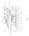
- FIGURE shows a half-section of a storage chamber formed for the storage of the high pressure shaft and the low pressure shaft of a gas turbine engine, hydraulically sealed between the high and the low pressure side bearing chamber.
- the high-pressure shaft 1 and the low-pressure shaft 2 of a gas turbine engine are mounted concentrically to one another on the turbine housing 4 via a first rolling bearing 3 for the high-pressure shaft 1 and a second rolling bearing (not shown) for the low-pressure shaft 2.
- the storage chamber 5 formed in this way is used for cooling and lubrication continuously supplied with coolant and lubricant (oil).
- the two preferably in the same direction rotating shafts, here the high pressure shaft 1 and the low pressure shaft 2, sealed against each other by means of a hydraulic seal.
- the hydraulic seal comprises a formed on the high-pressure shaft 1, to the rotation axis 7 towards open U-shaped annular space 8, which is filled due to the centrifugal forces acting through the rotation of the high-pressure shaft 1 with the introduced into the bearing chamber 5 coolant and lubricant, and a on Outer circumference of the low-pressure shaft 2 circumferential sealing ridge 9, which dips into the annular space 8 and in this during the rotation of the high-pressure shaft 1 sealing medium 10 and thus seals the low-pressure shaft 2 against the high-pressure shaft 1 and the low-pressure region in the storage chamber 5 relative to the high-pressure region 6.
- the U-shaped annular space 8 is formed by a first annular disc 11, a second annular disc 12 and an angle ring 13.
- the first annular disc 11 is integrally formed on the inside of the high pressure shaft 1 and has at its free edge a piston ring 14, which releases a narrow annular gap to the outside of the low pressure shaft 2 during rotation of the high pressure shaft and causes a seal at a standstill.
- first and second annular disc 11, 12 are the angle ring 13, whose horizontal leg is connected via radial spacers 16 fixed to the high-pressure shaft 1 and its low-pressure shaft 2 directed towards the vertical leg rests on axial spacers 17 on the second annular disc 12.
- the thus decoupled with a separate annular disc of the bearing bracket 20 on the high pressure shaft 1 annulus 8 has a low height and a low weight.
- the manufacturing and assembly costs are reduced compared to known similar hydraulic seal assemblies.
- the sealing medium 10 (coolant and lubricant, oil), which is continuously introduced into the annular space 8 during the rotation of the high-pressure shaft 1, flows after the heat absorption at the first annular disk 11 via the annular channel remaining between the angular ring 13 and the high-pressure shaft 1 or the second annular disk 12 18 quickly from the annular space 8 back into the storage chamber 5.
- the outlet opening 19 of the annular channel 18 is located at such a distance from the inner surface of the high-pressure shaft 1, namely radially inwardly above the free edge of the sealing web 9, that with continuous supply of cooling and lubricant in the storage chamber 5, a fast, ongoing replacement of the heated sealing medium 10 in the annular space 8 and thus its sufficient cooling, especially on the inner surface of the high temperatures most exposed first annular disc 11 is ensured.
- this arrangement of the outlet opening 19 ensures that even with insufficient, not exactly metered supply of coolant and lubricant in the storage chamber 5, a sealing effect of the hydraulic seal not impairing sealing medium in the annular chamber 8 is not exceeded and thus in any case the seal between high pressure area 6 and storage chamber 5 or between the high and the low pressure wave is ensured.
- the rapid continuous replacement of the coolant and lubricant, ie the sealing medium in the annular space 8 is supported by an angular arrangement and special design of the radial and axial spacers 16, 17 insofar as they exert a pumping action on the located in the annular chamber 8 sealing medium ,
- the active circulation of oil through the annular chamber 8 minimizes the likelihood of hot zones of hot oil resulting in coking and localized coal deposits and consequent degradation of oil supply.
- thermal protection arrangement In addition to the previously described measures for active oil circulation to avoid local overheating and coking and carbon deposition of the hydraulic seal for the storage chamber 5 on the high pressure side 6 is preceded by a thermal protection arrangement.
- This heat protection arrangement is realized in the present embodiment with an integrally formed on the high-pressure shaft 1 heat protection ring 21 and an air storage chamber 22 formed between this and the subsequent first annular web 11.
- the annular space 8 of the hydraulic seal and thus the circulating oil is heated less so that the risk of coking and deposits is further minimized and also the bearings for the high and the low pressure wave are better protected by a qualitatively unimpaired lubricant.
- projections 24 are formed on the angle ring.
Landscapes
- Engineering & Computer Science (AREA)
- General Engineering & Computer Science (AREA)
- Mechanical Engineering (AREA)
- Sealing Of Bearings (AREA)
- Sealing Devices (AREA)
- Turbine Rotor Nozzle Sealing (AREA)
Abstract
Description
- Die Erfindung betrifft eine hydraulische Wellendichtung für den Hochtemperaturbereich, insbesondere für konzentrisch angeordnete Wellen eines Gasturbinen-Triebwerks zur Abdichtung der im Niederdruckbereich liegenden Lagerkammer für die Hochdruckwelle und die Niederdruckwelle gegenüber dem Hochdruckbereich.
- Hydraulische Dichtungen werden bekanntermaßen zur berührungslosen Abdichtung zwischen zwei konzentrisch angeordneten, gleichsinnig rotierenden Wellen angewendet. Prinzipiell ist eine derartige Dichtung aber auch bei nur einer rotierenden Welle einsetzbar. Die Dichtung umfasst üblicherweise einen am Innenumfang der äußeren Welle vorgesehenen, im Wesentlichen U-förmigen Ringraum, in dem sich unter der Wirkung der Fliehkraft ein fließfähiges Dichtmedium, vorzugsweise Öl, aus dem Schmiermittelkreislauf der betreffenden Maschine, befindet. In das Dichtmedium in dem Ringraum taucht ein am Außenumfang der inneren Welle umlaufender Dichtsteg, um so eine berührungslose Abdichtung der beiden Wellen gegeneinander zu bewirken.
- Derartige hydraulische Dichtungen haben sich vielfach bewährt. Sie bereiten jedoch bei der Anwendung im Hochtemperaturbereich, vorzugsweise bei der Abdichtung der Lagerkammer für die Hochdruckwelle und die Niederdruckwelle eines Gasturbinen-Triebwerks gegenüber der mit einer Temperatur von beispielsweise 400°C zugeführten Verdichterluft, insofern Schwierigkeiten, als sich das als Dichtmedium verwendete Öl, das auch zum Schmieren der beiden Wellenlager dient, aufgrund der hohen Temperaturen zersetzen und verkoken kann. Insbesondere auf der dem Hochtemperaturbereich zugewandten Seite setzen sich an der Innenfläche des Ringraums feste Verkokungsprodukte ab, die sich im Betrieb lösen können und dem kontinuierlichen Nachfüllen von frischem, kühlerem Öl in den Ringraum und der durch den kontinuierlichen Ölaustausch bewirkten notwendigen Wärmeabfuhr sowie letztlich einer sicheren Abdichtung entgegenstehen.
- Eine derartige hydraulische Dichtung wird in der Anwendung bei einem Zweiwellen-Gasturbinen-Flugtriebwerk mit konzentrisch angeordneter Hoch- und Niederdruckwelle zur Abdichtung im Hochtemperaturbereich beispielsweise in der EP 1 045 178 A2 beschrieben. Der zur Aufnahme des Dichtmediums vorgesehene Ringraum, in den der Dichtsteg der Niederdruckwelle eingreift, ist unmittelbar aus dem Material der Hochdruckwelle ausgeformt. Daraus resultieren die durch eine erhebliche Baugröße und ein hohes Gewicht für ein Flugtriebwerk bekannten Nachteile. Die Zuführung des Dichtmediums in den Ringraum erfolgt kontinuierlich aus dem in die Lagerkammer zur Schmierung der Wälzlager der Hochdruckwelle und der Niederdruckwelle eingespritzten Öl. Eine Teilmenge des Dichtmediums im Ringraum wird entweder über eine Öffnung im Boden oder mit Hilfe eines Abschöpfbleches vom Boden über die obere Innenkante des Ringraums kontinuierlich abgezogen. Durch den ständigen Ölaustausch wird das Dichtmedium nicht zu hoch erhitzt und dadurch einem Verkoken entgegengewirkt. Das Abführen des Dichtmediums aus einem im Boden ausgeformten Ringraumbereich ist aber insofern nachteilig, als bei unzureichender Ölzufuhr nicht genügend Dichtmedium im Ringraum ist und mithin die Abdichtung gegenüber dem heißen Hochdruckbereich gestört ist. Beim Abführen des erhitzten Dichtmediums über den äußersten Rand des Ringraums wird das relativ heiße Dichtmedium auf einem langen Weg entlang der Wand eines in den Ringraum eingesetzten Winkelringes und der Ringrauminnenwand geführt, so dass sich auch hier Ölkohlepartikel absetzen können. Zudem kann es selbst bei einem kontinuierlichen Ölaustausch in dem Ringraum dennoch zur Ausbildung einer Kohleschicht an der heißen Innenwand des mit dem Dichtmedium gefüllten Ringraums kommen.
- Der Erfindung liegt daher die Aufgabe zugrunde, eine hydraulische Wellendichtung anzugeben, die auch im Hochtemperaturbereich eine Ölkohlebildung verhindert, für eine jederzeit sichere Abdichtung sorgt und die zudem platz-, gewichts- und montagezeitsparend ausgebildet ist und einen schnellen Ölaustausch gewährleistet.
- Erfindungsgemäß wird die Aufgabe mit einer gemäß den Merkmalen des Patentanspruchs 1 ausgebildeten hydraulischen Wellendichtung gelöst.
- Der Grundgedanke der Erfindung besteht in der Anordnung eines dem Ringraum für die Aufnahme des Dichtmediums im Abstand von dessen an den Hochdruck- bzw. Hochtemperaturbereich angrenzenden Seitenfläche vorgeschalteten Hitzeschutzring, der an der einen Welle angebracht ist und unter Ausbildung eines engen Dichtspaltes in geringem Abstand von der anderen Welle endet. Dadurch ist der Ringraum mit dem Dichtmedium durch ein Schutzschild und eine wärmeisolierende Luftkammer/Stagnationszone von der unmittelbaren Wärmeeinwirkung im Hochtemperaturbereich getrennt. Die Erwärmung des Dichtmediums und dessen Neigung zur Verkokung aufgrund hoher Temperaturen sowie zur Ablagerung von Ölkohlepartikeln an den besonders heißen Innenwandflächen des Ringraumes werden deutlich verringert. Der kontinuierliche Austausch des gesamten Dichtmediums im Ringraum wird aufgrund der verminderten Ölkohlebildung verbessert, so dass die Temperatur des Dichtmediums und die Verkokungsgefahr weiter minimiert werden.
- Gemäß einem weiteren wichtigen Merkmal der Erfindung sind an den Innenwänden des Ringraums Mittel angebracht, die bei der Rotation des Ringraums eine Pumpwirkung auf das Dichtmedium ausüben und den Medientransport über den Ringraum beschleunigen, d.h. das kontinuierliche Austauschen des Dichtmediums verbessern, so dass dessen Temperatur weiter verringert werden kann. Insbesondere in der Kombination aus für den Hitzeschutz und den verbesserten Medientransport bzw. -austausch vorgesehenen Maßnahmen kann die Temperatur des Dichtmediums so weit gesenkt werden, dass im Hochtemperaturbereich eine fehlerfreie Abdichtung der Hochdruckwelle gegenüber der Niederdruckwelle bzw. der an den Hochdruckbereich angrenzenden hinteren Lagerkammer und somit ein Schutz der betreffenden Wälzlager und der Kohlegleitringdichtung sowie eine sichere Funktion der Gasturbine gewährleistet sind. Ferner bewirkt die aktive Kühlung der Kohlegleitring-Lauffläche eine Verlängerung der Lebensdauer der eingesetzten Kohlegleitringdichtung.
- Gemäß einem weiteren wichtigen Merkmal der Erfindung ist der an der äußeren rotierenden Welle vorgesehene Ringraum zur Aufnahme des Dichtmediums aus einer an der Welle angeformten ersten Ringscheibe und einer separaten zweiten Ringscheibe gebildet. Dadurch wird die Montage der Welle vereinfacht sowie die Bauhöhe und das Gewicht in diesem Bereich verringert. In den Ringraum ist ein Winkelring so eingesetzt, dass das Dichtmedium nahe der am meisten erwärmten ersten Ringscheibe und nahe dem Boden über einen zwischen dem Boden und der zweiten Ringscheibe gebildeten Ringkanal über die nach innen weisende freie Kante der zweiten Ringscheibe in die Lagerkammer abfließen kann. Somit wird zuerst das heißeste, am ehesten verkokte Dichtmedium abgezogen, und zwar so, dass in jedem Fall, das heißt, auch bei einer Unterbrechung der Ölzufuhr, Dichtmedium in einem durch die Höhe der zweiten Ringscheibe vorgegebenen Flüssigkeitsstand in dem Ringraum verbleibt und die Dichtfunktion noch gewährleistet ist.
- In Ausgestaltung der Erfindung ist der Winkelring über mehrere Abstandhalter am Boden und an der zweiten Ringscheibe gehalten. Diese axialen und radialen Abstandhalter bilden in einer bestimmten schrägen Anordnung und Ausbildung die erfindungsgemäßen Mittel zur Erzeugung der Pumpwirkung für den beschleunigten Austausch des Dichtmediums in dem Ringraum der hydraulischen Wellendichtung.
- Ein Ausführungsbeispiel der Erfindung wird anhand der Zeichnung näher erläutert. Die einzige Figur zeigt einen Halbschnitt einer zur Lagerung der Hochdruckwelle und der Niederdruckwelle eines Gasturbinen-Triebwerks gebildeten, zwischen der Hoch- und der Niederdruckseite hydraulisch abgedichteten Lagerkammer.
- Die Hochdruckwelle 1 und die Niederdruckwelle 2 eines Gasturbinen-Triebwerks sind über ein erstes Wälzlager 3 für die Hochdruckwelle 1 und ein zweites Wälzlager (nicht dargestellt) für die Niederdruckwelle 2 konzentrisch zueinander am Turbinengehäuse 4 gelagert. Die auf diese Weise gebildete Lagerkammer 5 wird zur Kühlung und Schmierung kontinuierlich mit Kühl- und Schmiermittel (Öl) versorgt. Um den Niedrigdruckbereich in der Lagerkammer 5 gegenüber dem relativ heißen Hochdruckbereich 6 abzudichten und dadurch eine Verkokung und Entzündung des Öls zu verhindern, sind die beiden vorzugsweise gleichsinnig rotierenden Wellen, hier die Hochdruckwelle 1 und die Niederdruckwelle 2, mittels einer hydraulischen Dichtung gegeneinander abgedichtet. Die hydraulische Dichtung umfasst einen an der Hochdruckwelle 1 ausgebildeten, zur Rotationsachse 7 hin offenen U-förmigen Ringraum 8, der infolge der durch die Rotation der Hochdruckwelle 1 wirkenden Zentrifugalkräfte mit dem in die Lagerkammer 5 eingebrachten Kühl- und Schmiermittel gefüllt ist, sowie einen am Außenumfang der Niederdruckwelle 2 umlaufenden Dichtsteg 9, der in den Ringraum 8 und das in diesem während der Rotation der Hochdruckwelle 1 befindliche Dichtmedium 10 eintaucht und so die Niederdruckwelle 2 gegenüber der Hochdruckwelle 1 bzw. den Niederdruckbereich in der Lagerkammer 5 gegenüber dem Hochdruckbereich 6 abdichtet.
- Der U-förmige Ringraum 8 wird von einer ersten Ringscheibe 11, einer zweiten Ringscheibe 12 und einem Winkelring 13 gebildet. Die erste Ringscheibe 11 ist an der Innenseite der Hochdruckwelle 1 integral angeformt und hat an ihrem freien Rand einen Kolbenring 14, der während der Rotation der Hochdruckwelle einen schmalen Ringspalt zur Außenseite der Niederdruckwelle 2 hin freigibt und im Stillstand eine Abdichtung bewirkt. Die zweite Ringscheibe 12, die einen deutlich größeren Innenumfang als die erste Ringscheibe 11 hat, d.h. schmaler als dieser ist, wird mit Hilfe eines Sprengrings 15 an der Innenumfangsfläche der Hochdruckwelle 1 gehalten. Zwischen der ersten und der zweiten Ringscheibe 11, 12 befindet sich der Winkelring 13, dessen waagerechter Schenkel über radiale Abstandhalter 16 fest mit der Hochdruckwelle 1 verbunden ist und dessen zur Niederdruckwelle 2 hin gerichteter senkrechter Schenkel über axiale Abstandhalter 17 an der zweiten Ringscheibe 12 anliegt.
- Der so mit einer separaten Ringscheibe von dem Lagerträger 20 an der Hochdruckwelle 1 abgekoppelte Ringraum 8 hat eine geringe Bauhöhe und ein geringes Gewicht. Der Fertigungs- und Montageaufwand ist gegenüber bekannten ähnlichen hydraulischen Dichtungsanordnungen reduziert. Das während der Rotation der Hochdruckwelle 1 kontinuierlich in den Ringraum 8 eingebrachte Dichtmedium 10 (Kühl- und Schmiermittel; Öl) fließt nach der Wärmeaufnahme an der ersten Ringscheibe 11 über den zwischen dem Winkelring 13 und der Hochdruckwelle 1 bzw. der zweiten Ringscheibe 12 verbleibenden Ringkanal 18 schnell aus dem Ringraum 8 wieder in die Lagerkammer 5. Die Austrittsöffnung 19 des Ringkanals 18 befindet sich in einem solchen Abstand zur Innenfläche der Hochdruckwelle 1, und zwar radial nach innen oberhalb der freien Kante des Dichtsteges 9, dass bei kontinuierlicher Zufuhr des Kühl- und Schmiermittels in die Lagerkammer 5 ein schneller, laufender Austausch des erwärmtem Dichtmediums 10 in dem Ringraum 8 und damit auch dessen ausreichende Kühlung, insbesondere an der Innenfläche der den hohen Temperaturen am ehesten ausgesetzten ersten Ringscheibe 11, gewährleistet ist. Andererseits sorgt diese Anordnung der Austrittsöffnung 19 dafür, dass auch bei unzureichender, nicht exakt dosierter Zuführung von Kühl- und Schmiermittel in die Lagerkammer 5 ein die Dichtwirkung der hydraulischen Dichtung nicht beeinträchtigender Dichtmedium-stand in der Ringkammer 8 nicht unterschritten wird und damit in jedem Fall die Abdichtung zwischen Hochdruckbereich 6 und Lagerkammer 5 bzw. zwischen der Hoch- und der Niederdruckwelle sichergestellt ist. Der schnelle kontinuierliche Austausch des Kühl- und Schmiermittels, d.h. des Dichtmediums in dem Ringraum 8, wird durch eine winklige Anordnung und besondere Ausbildung der radialen und axialen Abstandhalter 16, 17 insofern unterstützt, als diese eine Pumpwirkung auf das in der Ringkammer 8 befindliche Dichtmedium ausüben. Durch die aktive Ölzirkulation über die Ringkammer 8 wird die Wahrscheinlichkeit des Auftretens von Zonen heißen Öls mit der Folge von Verkokungen und örtlichen Kohleablagerungen und einer dadurch bedingten Beeinträchtigung der Ölzufuhr minimiert.
- Zusätzlich zu den zuvor beschriebenen Maßnahmen zur aktiven Ölzirkulation zur Vermeidung örtlicher Überhitzung sowie Verkokung und Kohleablagerung ist der hydraulischen Dichtung für die Lagerkammer 5 auf der Hochdruckseite 6 eine Wärmeschutzanordnung vorgeschaltet. Diese Wärmeschutzanordnung wird in der vorliegenden Ausführungsform mit einem an der Hochdruckwelle 1 angeformten Hitzeschutzring 21 und einer zwischen diesem und dem anschließenden ersten Ringsteg 11 gebildeten Luftstaukammer 22 realisiert. Dadurch wird der Ringraum 8 der hydraulischen Dichtung und mithin das zirkulierende Öl weniger stark erwärmt, so dass die Gefahr von Verkokungen und Ablagerungen weiter minimiert wird und auch die Wälzlager für die Hoch- und die Niederdruckwelle durch ein qualitativ nicht beeinträchtigtes Schmiermittel besser geschützt sind. Zur Verwirbelung des Dichtmediums und zur weiteren Verbesserung des Dichtmedientransports im Ringraum 8 sind an dem Winkelring 13 Vorsprünge 24 angeformt.
-
- 1
- Hochdruckwelle
- 2
- Niederdruckwelle
- 3
- Wälzlager von 1
- 4
- Turbinengehäuse
- 5
- Lagerkammer (Niedrigdruckbereich)
- 6
- Hochdruckbereich (Hochtemperaturbereich)
- 7
- Rotationsachse von 1, 2
- 8
- U-förmiger Ringraum
- 9
- Dichtsteg
- 10
- Dichtmedium
- 11
- Erste (angeformte) Ringscheibe v. 8
- 12
- Zweite (separate) Ringscheibe v. 8
- 13
- Winkelring v. 8
- 14
- Kolbenring
- 15
- Sprengring
- 16
- Radialer Abstandhalter
- 17
- Axialer Abstandhalter
- 18
- Ringkanal (Ablaufkanal)
- 19
- Austrittsöffnung v. 18
- 20
- Lagerträger v. 1
- 21
- Hitzeschutzring
- 22
- Luftkammer/Stagnationszone
- 23
- Dichtspalt
- 24
- Vorsprünge, Verwirbelungsmittel
Claims (6)
- Hydraulische Wellendichtung für den Hochtemperaturbereich, insbesondere für konzentrisch angeordnete Wellen (1, 2) eines Gasturbinen-Triebwerks zur Abdichtung der im Niederdruckbereich liegenden Lagerkammer (5) für die Hochdruckwelle (1) und die Niederdruckwelle (2) gegenüber dem Hochdruckbereich (6), mit einem im Wesentlichen U-förmigen, am Innenumfang der Hochdruckwelle (1) umlaufenden Ringraum (8), in dem sich ein durch Fliehkräfte gehaltenes, kontinuierlich ausgetauschtes Dichtmedium (10) befindet, sowie einem in das Dichtmedium (10) eintauchenden ringförmigen Dichtsteg (9), dadurch gekennzeichnet, dass dem Ringraum (8) im Hochdruckbereich (6) in bestimmtem Abstand zum Ringraum (8) und mit einem zur Niederdruckwelle (2) verbleibenden Dichtspalt (23) ein Hitzeschutzring (21) als Wärmeschutzschild und zur Ausbildung einer wärmeisolierenden Luftkammer (22) vorgeschaltet ist.
- Hydraulische Wellendichtung nach Anspruch 1, dadurch gekennzeichnet, dass der Hitzeschutzring (21) einstückig an die Hochdruckwelle (1) angeformt ist.
- Hydraulische Wellendichtung nach Anspruch 1, dadurch gekennzeichnet, dass der U-förmige Ringraum (8) eine nahe dem Hitzeschutzring (21) an die Hochdruckwelle (1) angeformte erste Ringscheibe (11) und eine von der Hochdruckwelle (1) abgekoppelte zweite Ringscheibe (12) sowie einen im Abstand von der Innenfläche der Hochdruckwelle (1) und der zweiten Ringscheibe (12) fixierten umlaufenden Winkelring (13) umfasst, wobei in dem von dem Winkelring und dem Ringraum (8) gebildeten Ringkanal (18), der zum Abführen des erhitzten Dichtmediums an einer in Höhe der freien Kante des zweiten Ringsteges (12) liegenden Austrittsöffnung (19) vorgesehen ist, mehrere Abstandhalter (16, 17) angeordnet sind, die aufgrund ihrer Ausbildung und Ausrichtung eine Pumpwirkung auf das abzuführende erwärmte Dichtmedium ausüben.
- Hydraulische Wellendichtung nach Anspruch 3, dadurch gekennzeichnet, dass die separat ausgebildete zweite Ringscheibe (12) mit Hilfe eines Sprengringes (15) unmittelbar am Lagerträger (20) der Hochdruckwelle (1) montiert ist.
- Hydraulische Wellendichtung nach Anspruch 3, dadurch gekennzeichnet, dass an der freien Kante der Ringscheiben (11 und/oder 21) ein Kolbenring (14) angebracht ist, der bei der Rotation der Hochdruckwelle (1) einen engen Ringspalt freigibt.
- Hydraulische Wellendichtung nach Anspruch 3, dadurch gekennzeichnet, dass an den Winkelring (13) auf der zum Ringraum (8) weisenden Seitenfläche Vorsprünge (24) zur Verwirbelung des Dichtmediums und zur Verbesserung des Dichtmedientransports im Ringraum (8) angebracht sind.
Applications Claiming Priority (1)
| Application Number | Priority Date | Filing Date | Title |
|---|---|---|---|
| DE102004040242A DE102004040242A1 (de) | 2004-08-13 | 2004-08-13 | Hydraulische Wellendichtung für den Hochtemperaturbereich |
Publications (2)
| Publication Number | Publication Date |
|---|---|
| EP1626164A1 true EP1626164A1 (de) | 2006-02-15 |
| EP1626164B1 EP1626164B1 (de) | 2007-09-05 |
Family
ID=35094565
Family Applications (1)
| Application Number | Title | Priority Date | Filing Date |
|---|---|---|---|
| EP05107166A Expired - Lifetime EP1626164B1 (de) | 2004-08-13 | 2005-08-03 | Hydraulische Wellendichtung für den Hochtemperaturbereich |
Country Status (3)
| Country | Link |
|---|---|
| US (1) | US7344139B2 (de) |
| EP (1) | EP1626164B1 (de) |
| DE (2) | DE102004040242A1 (de) |
Cited By (3)
| Publication number | Priority date | Publication date | Assignee | Title |
|---|---|---|---|---|
| WO2008065359A3 (en) * | 2006-11-28 | 2008-07-31 | Cummins Turbo Tech Ltd | Hydraulic seal for a turbocharger |
| DE102009054007A1 (de) * | 2009-11-19 | 2011-05-26 | Rolls-Royce Deutschland Ltd & Co Kg | Gasturbine mit hydraulischer Dichtung |
| EP3006677A1 (de) * | 2014-10-06 | 2016-04-13 | Rolls-Royce Deutschland Ltd & Co KG | Gasturbine mit wenigstens zwei koaxial zueinander angeordneten und zumindest bereichsweise als hohlwellen ausgebildeten wellen |
Families Citing this family (12)
| Publication number | Priority date | Publication date | Assignee | Title |
|---|---|---|---|---|
| US7878303B2 (en) * | 2006-11-14 | 2011-02-01 | Rolls-Royce Corporation | Lubrication scavenge system |
| DE102007060890A1 (de) | 2007-12-14 | 2009-06-18 | Rolls-Royce Deutschland Ltd & Co Kg | Abdichtung mindestens einer Welle mit mindestens einer hydraulischen Dichtung |
| GB0818726D0 (en) * | 2008-10-14 | 2008-11-19 | Rolls Royce Plc | A seal |
| FR2983908B1 (fr) * | 2011-12-08 | 2015-02-20 | Snecma | Systeme pour assurer l’etancheite entre une enceinte d’huile et un volume exterieur attenant et turbomachine equipee d’un tel systeme d’etancheite. |
| DE102012011144A1 (de) * | 2012-06-05 | 2013-12-05 | Rolls-Royce Deutschland Ltd & Co Kg | Hydraulische Dichtungsanordnung |
| WO2014138617A1 (en) | 2013-03-08 | 2014-09-12 | United Technologies Corporation | Fluid-cooled seal arrangement for a gas turbine engine |
| WO2015094463A1 (en) * | 2013-12-20 | 2015-06-25 | United Technologies Corporation | Seal runner |
| US10577973B2 (en) | 2016-02-18 | 2020-03-03 | General Electric Company | Service tube for a turbine engine |
| US10371263B2 (en) | 2017-06-23 | 2019-08-06 | United Technologies Corporation | Hydraulic seal for non-mainshaft, rotating to static |
| FR3075861B1 (fr) * | 2017-12-22 | 2019-11-15 | Safran Aircraft Engines | Etancheite dynamique entre deux rotors d'une turbomachine d'aeronef |
| NL2029488B1 (en) * | 2021-10-22 | 2023-05-16 | Univ Gent | Rotation device, electric motor or electric generator, gear box, turbomachine, and flow control device |
| CN114542205B (zh) * | 2022-02-11 | 2022-11-22 | 中国航发沈阳发动机研究所 | 一种高马赫航空发动机耐高温高压轴承腔结构 |
Citations (4)
| Publication number | Priority date | Publication date | Assignee | Title |
|---|---|---|---|---|
| US4157881A (en) * | 1976-08-19 | 1979-06-12 | Kabushiki Kaisha Komatsu Seisakusho | Turbosupercharger |
| GB2125118A (en) * | 1982-08-03 | 1984-02-29 | Rolls Royce | Hydraulic seal |
| EP1045178A2 (de) * | 1999-04-14 | 2000-10-18 | Rolls-Royce Deutschland GmbH | Hydraulische Dichtungsanordnung insbesondere an einer Gasturbine |
| EP1327802A2 (de) * | 2002-01-14 | 2003-07-16 | Rolls-Royce Deutschland Ltd & Co KG | Hydraulische Dichtungsanordnung |
Family Cites Families (5)
| Publication number | Priority date | Publication date | Assignee | Title |
|---|---|---|---|---|
| DE1822762U (de) * | 1959-07-31 | 1960-12-01 | Entwicklungsbau Pirna Veb | Hydrodynamische dichtung fuer schnell umlaufende wellen. |
| BE621931A (de) * | 1961-08-30 | |||
| GB1284596A (en) * | 1969-12-20 | 1972-08-09 | Rolls Royce | Improvements in or relating to hydraulic seals |
| GB9801561D0 (en) * | 1998-01-27 | 1998-03-25 | Rolls Royce Plc | Hydraulic seal |
| DE19956919A1 (de) * | 1999-11-26 | 2001-05-31 | Rolls Royce Deutschland | Gasturbinen-Triebwerk mit einer Lagerkammer |
-
2004
- 2004-08-13 DE DE102004040242A patent/DE102004040242A1/de not_active Withdrawn
-
2005
- 2005-08-03 DE DE502005001407T patent/DE502005001407D1/de not_active Expired - Lifetime
- 2005-08-03 EP EP05107166A patent/EP1626164B1/de not_active Expired - Lifetime
- 2005-08-15 US US11/203,199 patent/US7344139B2/en not_active Expired - Lifetime
Patent Citations (4)
| Publication number | Priority date | Publication date | Assignee | Title |
|---|---|---|---|---|
| US4157881A (en) * | 1976-08-19 | 1979-06-12 | Kabushiki Kaisha Komatsu Seisakusho | Turbosupercharger |
| GB2125118A (en) * | 1982-08-03 | 1984-02-29 | Rolls Royce | Hydraulic seal |
| EP1045178A2 (de) * | 1999-04-14 | 2000-10-18 | Rolls-Royce Deutschland GmbH | Hydraulische Dichtungsanordnung insbesondere an einer Gasturbine |
| EP1327802A2 (de) * | 2002-01-14 | 2003-07-16 | Rolls-Royce Deutschland Ltd & Co KG | Hydraulische Dichtungsanordnung |
Cited By (8)
| Publication number | Priority date | Publication date | Assignee | Title |
|---|---|---|---|---|
| WO2008065359A3 (en) * | 2006-11-28 | 2008-07-31 | Cummins Turbo Tech Ltd | Hydraulic seal for a turbocharger |
| GB2456483A (en) * | 2006-11-28 | 2009-07-22 | Cummins Turbo Technologies | Hydraulic seal for a turbocharger |
| GB2456483B (en) * | 2006-11-28 | 2011-03-16 | Cummins Turbo Technologies | Hydraulic seal for a turbocharger |
| US8075251B2 (en) | 2006-11-28 | 2011-12-13 | Cummins Turbo Technologies Limited | Hydraulic seal for a turbocharger |
| DE102009054007A1 (de) * | 2009-11-19 | 2011-05-26 | Rolls-Royce Deutschland Ltd & Co Kg | Gasturbine mit hydraulischer Dichtung |
| DE102009054007B4 (de) * | 2009-11-19 | 2018-02-08 | Rolls-Royce Deutschland Ltd & Co Kg | Gasturbine mit hydraulischer Dichtung |
| EP3006677A1 (de) * | 2014-10-06 | 2016-04-13 | Rolls-Royce Deutschland Ltd & Co KG | Gasturbine mit wenigstens zwei koaxial zueinander angeordneten und zumindest bereichsweise als hohlwellen ausgebildeten wellen |
| US10082037B2 (en) | 2014-10-06 | 2018-09-25 | Rolls-Royce Deutschland Ltd & Co Kg | Gas turbine having at least two shafts designed as hollow shafts at least in some areas and arranged coaxially relative to one another |
Also Published As
| Publication number | Publication date |
|---|---|
| DE102004040242A1 (de) | 2006-02-23 |
| US20060033289A1 (en) | 2006-02-16 |
| DE502005001407D1 (de) | 2007-10-18 |
| US7344139B2 (en) | 2008-03-18 |
| EP1626164B1 (de) | 2007-09-05 |
Similar Documents
| Publication | Publication Date | Title |
|---|---|---|
| EP1626164B1 (de) | Hydraulische Wellendichtung für den Hochtemperaturbereich | |
| EP1045178B1 (de) | Hydraulische Dichtungsanordnung insbesondere an einer Gasturbine | |
| DE69607718T2 (de) | Wälzlager mit dynamischer, ölversorgter Drainage | |
| DE3320095C2 (de) | Dichtung für ein Wellenlager | |
| EP2071131B1 (de) | Abdichtung mindestens einer Welle mit mindestens einer hydraulischen Dichtung | |
| DE3751295T2 (de) | Turbolader. | |
| DE60004772T2 (de) | Dichtungsanordnung | |
| DE602004000658T2 (de) | Dichtungsanordnung | |
| DE1954971A1 (de) | Dichtungseinrichtung | |
| DE1077013B (de) | Gleitringdichtung | |
| EP2815139B1 (de) | Radiallager | |
| EP2607757B1 (de) | Gleitringdichtung | |
| DE3840487A1 (de) | Dichtung fuer eine zylinderflaeche | |
| DE3925403C2 (de) | Trockengasdichtung | |
| EP3091242A1 (de) | Gleitlager mit schmiernut | |
| EP0806578B1 (de) | Dichtkopf zum Transport eines Wärmeträgermediums zu einem rotierenden Drucksystem | |
| DE1933287A1 (de) | Rotationsmaschine | |
| DE112017001057B4 (de) | Radialgleitlager und rotationsmaschine | |
| EP0465890B1 (de) | Beölungssystem für eine Bremsscheibe | |
| EP1507106A1 (de) | Rotationsdichtung | |
| DE2503856C3 (de) | ||
| DE2209345C3 (de) | Vorrichtung zum Schmieren und Kühlen eines Lagers | |
| EP1479929A2 (de) | Axialgleitlageranordnung | |
| DE102016124283A1 (de) | Hydrodynamische Kupplung | |
| DE102017106942A1 (de) | Hydrodynamische Kupplung |
Legal Events
| Date | Code | Title | Description |
|---|---|---|---|
| PUAI | Public reference made under article 153(3) epc to a published international application that has entered the european phase |
Free format text: ORIGINAL CODE: 0009012 |
|
| AK | Designated contracting states |
Kind code of ref document: A1 Designated state(s): AT BE BG CH CY CZ DE DK EE ES FI FR GB GR HU IE IS IT LI LT LU LV MC NL PL PT RO SE SI SK TR |
|
| AX | Request for extension of the european patent |
Extension state: AL BA HR MK YU |
|
| 17P | Request for examination filed |
Effective date: 20060313 |
|
| AKX | Designation fees paid |
Designated state(s): DE FR GB |
|
| GRAP | Despatch of communication of intention to grant a patent |
Free format text: ORIGINAL CODE: EPIDOSNIGR1 |
|
| GRAS | Grant fee paid |
Free format text: ORIGINAL CODE: EPIDOSNIGR3 |
|
| RIN1 | Information on inventor provided before grant (corrected) |
Inventor name: HEIN, STEFAN Inventor name: GAEBLER, MIKLOS |
|
| GRAA | (expected) grant |
Free format text: ORIGINAL CODE: 0009210 |
|
| AK | Designated contracting states |
Kind code of ref document: B1 Designated state(s): DE FR GB |
|
| REG | Reference to a national code |
Ref country code: GB Ref legal event code: FG4D Free format text: NOT ENGLISH |
|
| RIN1 | Information on inventor provided before grant (corrected) |
Inventor name: GAEBLER, MIKLOS Inventor name: HEIN, STEFAN |
|
| GBT | Gb: translation of ep patent filed (gb section 77(6)(a)/1977) |
Effective date: 20070920 |
|
| REF | Corresponds to: |
Ref document number: 502005001407 Country of ref document: DE Date of ref document: 20071018 Kind code of ref document: P |
|
| EN | Fr: translation not filed | ||
| PLBE | No opposition filed within time limit |
Free format text: ORIGINAL CODE: 0009261 |
|
| STAA | Information on the status of an ep patent application or granted ep patent |
Free format text: STATUS: NO OPPOSITION FILED WITHIN TIME LIMIT |
|
| ET | Fr: translation filed | ||
| REG | Reference to a national code |
Ref country code: FR Ref legal event code: EERR Free format text: CORRECTION DE BOPI 08/18 - BREVETS EUROPEENS DONT LA TRADUCTION N A PAS ETE REMISE A L INPI. IL Y A LIEU DE SUPPRIMER : LA MENTION DE LA NON-REMISE. LA REMISE DE LA TRADUCTION EST PUBLIEE DANS LE PRESENT BOPI. |
|
| 26N | No opposition filed |
Effective date: 20080606 |
|
| PG25 | Lapsed in a contracting state [announced via postgrant information from national office to epo] |
Ref country code: FR Free format text: LAPSE BECAUSE OF FAILURE TO SUBMIT A TRANSLATION OF THE DESCRIPTION OR TO PAY THE FEE WITHIN THE PRESCRIBED TIME-LIMIT Effective date: 20080502 |
|
| REG | Reference to a national code |
Ref country code: FR Ref legal event code: PLFP Year of fee payment: 12 |
|
| REG | Reference to a national code |
Ref country code: FR Ref legal event code: PLFP Year of fee payment: 13 |
|
| REG | Reference to a national code |
Ref country code: FR Ref legal event code: PLFP Year of fee payment: 14 |
|
| REG | Reference to a national code |
Ref country code: DE Ref legal event code: R082 Ref document number: 502005001407 Country of ref document: DE Representative=s name: ETL WABLAT & KOLLEGEN PATENT- UND RECHTSANWALT, DE Ref country code: DE Ref legal event code: R082 Ref document number: 502005001407 Country of ref document: DE Representative=s name: ETL IP PATENT- UND RECHTSANWALTSGESELLSCHAFT M, DE |
|
| PGFP | Annual fee paid to national office [announced via postgrant information from national office to epo] |
Ref country code: DE Payment date: 20190828 Year of fee payment: 15 Ref country code: FR Payment date: 20190826 Year of fee payment: 15 |
|
| PGFP | Annual fee paid to national office [announced via postgrant information from national office to epo] |
Ref country code: GB Payment date: 20190827 Year of fee payment: 15 |
|
| REG | Reference to a national code |
Ref country code: DE Ref legal event code: R082 Ref document number: 502005001407 Country of ref document: DE Representative=s name: ETL IP PATENT- UND RECHTSANWALTSGESELLSCHAFT M, DE |
|
| REG | Reference to a national code |
Ref country code: DE Ref legal event code: R119 Ref document number: 502005001407 Country of ref document: DE |
|
| GBPC | Gb: european patent ceased through non-payment of renewal fee |
Effective date: 20200803 |
|
| PG25 | Lapsed in a contracting state [announced via postgrant information from national office to epo] |
Ref country code: FR Free format text: LAPSE BECAUSE OF NON-PAYMENT OF DUE FEES Effective date: 20200831 Ref country code: DE Free format text: LAPSE BECAUSE OF NON-PAYMENT OF DUE FEES Effective date: 20210302 |
|
| PG25 | Lapsed in a contracting state [announced via postgrant information from national office to epo] |
Ref country code: GB Free format text: LAPSE BECAUSE OF NON-PAYMENT OF DUE FEES Effective date: 20200803 |