EP1625962A2 - Power Switchover Apparatus for a hybrid vehicle - Google Patents
Power Switchover Apparatus for a hybrid vehicle Download PDFInfo
- Publication number
- EP1625962A2 EP1625962A2 EP05254343A EP05254343A EP1625962A2 EP 1625962 A2 EP1625962 A2 EP 1625962A2 EP 05254343 A EP05254343 A EP 05254343A EP 05254343 A EP05254343 A EP 05254343A EP 1625962 A2 EP1625962 A2 EP 1625962A2
- Authority
- EP
- European Patent Office
- Prior art keywords
- rotational speed
- engine
- power
- transmission ratio
- transmission
- Prior art date
- Legal status (The legal status is an assumption and is not a legal conclusion. Google has not performed a legal analysis and makes no representation as to the accuracy of the status listed.)
- Granted
Links
Images


Classifications
-
- B—PERFORMING OPERATIONS; TRANSPORTING
- B60—VEHICLES IN GENERAL
- B60W—CONJOINT CONTROL OF VEHICLE SUB-UNITS OF DIFFERENT TYPE OR DIFFERENT FUNCTION; CONTROL SYSTEMS SPECIALLY ADAPTED FOR HYBRID VEHICLES; ROAD VEHICLE DRIVE CONTROL SYSTEMS FOR PURPOSES NOT RELATED TO THE CONTROL OF A PARTICULAR SUB-UNIT
- B60W20/00—Control systems specially adapted for hybrid vehicles
- B60W20/30—Control strategies involving selection of transmission gear ratio
-
- B—PERFORMING OPERATIONS; TRANSPORTING
- B60—VEHICLES IN GENERAL
- B60K—ARRANGEMENT OR MOUNTING OF PROPULSION UNITS OR OF TRANSMISSIONS IN VEHICLES; ARRANGEMENT OR MOUNTING OF PLURAL DIVERSE PRIME-MOVERS IN VEHICLES; AUXILIARY DRIVES FOR VEHICLES; INSTRUMENTATION OR DASHBOARDS FOR VEHICLES; ARRANGEMENTS IN CONNECTION WITH COOLING, AIR INTAKE, GAS EXHAUST OR FUEL SUPPLY OF PROPULSION UNITS IN VEHICLES
- B60K6/00—Arrangement or mounting of plural diverse prime-movers for mutual or common propulsion, e.g. hybrid propulsion systems comprising electric motors and internal combustion engines ; Control systems therefor, i.e. systems controlling two or more prime movers, or controlling one of these prime movers and any of the transmission, drive or drive units Informative references: mechanical gearings with secondary electric drive F16H3/72; arrangements for handling mechanical energy structurally associated with the dynamo-electric machine H02K7/00; machines comprising structurally interrelated motor and generator parts H02K51/00; dynamo-electric machines not otherwise provided for in H02K see H02K99/00
- B60K6/20—Arrangement or mounting of plural diverse prime-movers for mutual or common propulsion, e.g. hybrid propulsion systems comprising electric motors and internal combustion engines ; Control systems therefor, i.e. systems controlling two or more prime movers, or controlling one of these prime movers and any of the transmission, drive or drive units Informative references: mechanical gearings with secondary electric drive F16H3/72; arrangements for handling mechanical energy structurally associated with the dynamo-electric machine H02K7/00; machines comprising structurally interrelated motor and generator parts H02K51/00; dynamo-electric machines not otherwise provided for in H02K see H02K99/00 the prime-movers consisting of electric motors and internal combustion engines, e.g. HEVs
- B60K6/22—Arrangement or mounting of plural diverse prime-movers for mutual or common propulsion, e.g. hybrid propulsion systems comprising electric motors and internal combustion engines ; Control systems therefor, i.e. systems controlling two or more prime movers, or controlling one of these prime movers and any of the transmission, drive or drive units Informative references: mechanical gearings with secondary electric drive F16H3/72; arrangements for handling mechanical energy structurally associated with the dynamo-electric machine H02K7/00; machines comprising structurally interrelated motor and generator parts H02K51/00; dynamo-electric machines not otherwise provided for in H02K see H02K99/00 the prime-movers consisting of electric motors and internal combustion engines, e.g. HEVs characterised by apparatus, components or means specially adapted for HEVs
- B60K6/38—Arrangement or mounting of plural diverse prime-movers for mutual or common propulsion, e.g. hybrid propulsion systems comprising electric motors and internal combustion engines ; Control systems therefor, i.e. systems controlling two or more prime movers, or controlling one of these prime movers and any of the transmission, drive or drive units Informative references: mechanical gearings with secondary electric drive F16H3/72; arrangements for handling mechanical energy structurally associated with the dynamo-electric machine H02K7/00; machines comprising structurally interrelated motor and generator parts H02K51/00; dynamo-electric machines not otherwise provided for in H02K see H02K99/00 the prime-movers consisting of electric motors and internal combustion engines, e.g. HEVs characterised by apparatus, components or means specially adapted for HEVs characterised by the driveline clutches
- B60K6/383—One-way clutches or freewheel devices
-
- B—PERFORMING OPERATIONS; TRANSPORTING
- B60—VEHICLES IN GENERAL
- B60K—ARRANGEMENT OR MOUNTING OF PROPULSION UNITS OR OF TRANSMISSIONS IN VEHICLES; ARRANGEMENT OR MOUNTING OF PLURAL DIVERSE PRIME-MOVERS IN VEHICLES; AUXILIARY DRIVES FOR VEHICLES; INSTRUMENTATION OR DASHBOARDS FOR VEHICLES; ARRANGEMENTS IN CONNECTION WITH COOLING, AIR INTAKE, GAS EXHAUST OR FUEL SUPPLY OF PROPULSION UNITS IN VEHICLES
- B60K6/00—Arrangement or mounting of plural diverse prime-movers for mutual or common propulsion, e.g. hybrid propulsion systems comprising electric motors and internal combustion engines ; Control systems therefor, i.e. systems controlling two or more prime movers, or controlling one of these prime movers and any of the transmission, drive or drive units Informative references: mechanical gearings with secondary electric drive F16H3/72; arrangements for handling mechanical energy structurally associated with the dynamo-electric machine H02K7/00; machines comprising structurally interrelated motor and generator parts H02K51/00; dynamo-electric machines not otherwise provided for in H02K see H02K99/00
- B60K6/20—Arrangement or mounting of plural diverse prime-movers for mutual or common propulsion, e.g. hybrid propulsion systems comprising electric motors and internal combustion engines ; Control systems therefor, i.e. systems controlling two or more prime movers, or controlling one of these prime movers and any of the transmission, drive or drive units Informative references: mechanical gearings with secondary electric drive F16H3/72; arrangements for handling mechanical energy structurally associated with the dynamo-electric machine H02K7/00; machines comprising structurally interrelated motor and generator parts H02K51/00; dynamo-electric machines not otherwise provided for in H02K see H02K99/00 the prime-movers consisting of electric motors and internal combustion engines, e.g. HEVs
- B60K6/22—Arrangement or mounting of plural diverse prime-movers for mutual or common propulsion, e.g. hybrid propulsion systems comprising electric motors and internal combustion engines ; Control systems therefor, i.e. systems controlling two or more prime movers, or controlling one of these prime movers and any of the transmission, drive or drive units Informative references: mechanical gearings with secondary electric drive F16H3/72; arrangements for handling mechanical energy structurally associated with the dynamo-electric machine H02K7/00; machines comprising structurally interrelated motor and generator parts H02K51/00; dynamo-electric machines not otherwise provided for in H02K see H02K99/00 the prime-movers consisting of electric motors and internal combustion engines, e.g. HEVs characterised by apparatus, components or means specially adapted for HEVs
- B60K6/40—Arrangement or mounting of plural diverse prime-movers for mutual or common propulsion, e.g. hybrid propulsion systems comprising electric motors and internal combustion engines ; Control systems therefor, i.e. systems controlling two or more prime movers, or controlling one of these prime movers and any of the transmission, drive or drive units Informative references: mechanical gearings with secondary electric drive F16H3/72; arrangements for handling mechanical energy structurally associated with the dynamo-electric machine H02K7/00; machines comprising structurally interrelated motor and generator parts H02K51/00; dynamo-electric machines not otherwise provided for in H02K see H02K99/00 the prime-movers consisting of electric motors and internal combustion engines, e.g. HEVs characterised by apparatus, components or means specially adapted for HEVs characterised by the assembly or relative disposition of components
- B60K6/405—Housings
-
- B—PERFORMING OPERATIONS; TRANSPORTING
- B60—VEHICLES IN GENERAL
- B60K—ARRANGEMENT OR MOUNTING OF PROPULSION UNITS OR OF TRANSMISSIONS IN VEHICLES; ARRANGEMENT OR MOUNTING OF PLURAL DIVERSE PRIME-MOVERS IN VEHICLES; AUXILIARY DRIVES FOR VEHICLES; INSTRUMENTATION OR DASHBOARDS FOR VEHICLES; ARRANGEMENTS IN CONNECTION WITH COOLING, AIR INTAKE, GAS EXHAUST OR FUEL SUPPLY OF PROPULSION UNITS IN VEHICLES
- B60K6/00—Arrangement or mounting of plural diverse prime-movers for mutual or common propulsion, e.g. hybrid propulsion systems comprising electric motors and internal combustion engines ; Control systems therefor, i.e. systems controlling two or more prime movers, or controlling one of these prime movers and any of the transmission, drive or drive units Informative references: mechanical gearings with secondary electric drive F16H3/72; arrangements for handling mechanical energy structurally associated with the dynamo-electric machine H02K7/00; machines comprising structurally interrelated motor and generator parts H02K51/00; dynamo-electric machines not otherwise provided for in H02K see H02K99/00
- B60K6/20—Arrangement or mounting of plural diverse prime-movers for mutual or common propulsion, e.g. hybrid propulsion systems comprising electric motors and internal combustion engines ; Control systems therefor, i.e. systems controlling two or more prime movers, or controlling one of these prime movers and any of the transmission, drive or drive units Informative references: mechanical gearings with secondary electric drive F16H3/72; arrangements for handling mechanical energy structurally associated with the dynamo-electric machine H02K7/00; machines comprising structurally interrelated motor and generator parts H02K51/00; dynamo-electric machines not otherwise provided for in H02K see H02K99/00 the prime-movers consisting of electric motors and internal combustion engines, e.g. HEVs
- B60K6/42—Arrangement or mounting of plural diverse prime-movers for mutual or common propulsion, e.g. hybrid propulsion systems comprising electric motors and internal combustion engines ; Control systems therefor, i.e. systems controlling two or more prime movers, or controlling one of these prime movers and any of the transmission, drive or drive units Informative references: mechanical gearings with secondary electric drive F16H3/72; arrangements for handling mechanical energy structurally associated with the dynamo-electric machine H02K7/00; machines comprising structurally interrelated motor and generator parts H02K51/00; dynamo-electric machines not otherwise provided for in H02K see H02K99/00 the prime-movers consisting of electric motors and internal combustion engines, e.g. HEVs characterised by the architecture of the hybrid electric vehicle
- B60K6/48—Parallel type
- B60K6/485—Motor-assist type
-
- B—PERFORMING OPERATIONS; TRANSPORTING
- B60—VEHICLES IN GENERAL
- B60K—ARRANGEMENT OR MOUNTING OF PROPULSION UNITS OR OF TRANSMISSIONS IN VEHICLES; ARRANGEMENT OR MOUNTING OF PLURAL DIVERSE PRIME-MOVERS IN VEHICLES; AUXILIARY DRIVES FOR VEHICLES; INSTRUMENTATION OR DASHBOARDS FOR VEHICLES; ARRANGEMENTS IN CONNECTION WITH COOLING, AIR INTAKE, GAS EXHAUST OR FUEL SUPPLY OF PROPULSION UNITS IN VEHICLES
- B60K6/00—Arrangement or mounting of plural diverse prime-movers for mutual or common propulsion, e.g. hybrid propulsion systems comprising electric motors and internal combustion engines ; Control systems therefor, i.e. systems controlling two or more prime movers, or controlling one of these prime movers and any of the transmission, drive or drive units Informative references: mechanical gearings with secondary electric drive F16H3/72; arrangements for handling mechanical energy structurally associated with the dynamo-electric machine H02K7/00; machines comprising structurally interrelated motor and generator parts H02K51/00; dynamo-electric machines not otherwise provided for in H02K see H02K99/00
- B60K6/20—Arrangement or mounting of plural diverse prime-movers for mutual or common propulsion, e.g. hybrid propulsion systems comprising electric motors and internal combustion engines ; Control systems therefor, i.e. systems controlling two or more prime movers, or controlling one of these prime movers and any of the transmission, drive or drive units Informative references: mechanical gearings with secondary electric drive F16H3/72; arrangements for handling mechanical energy structurally associated with the dynamo-electric machine H02K7/00; machines comprising structurally interrelated motor and generator parts H02K51/00; dynamo-electric machines not otherwise provided for in H02K see H02K99/00 the prime-movers consisting of electric motors and internal combustion engines, e.g. HEVs
- B60K6/50—Architecture of the driveline characterised by arrangement or kind of transmission units
- B60K6/54—Transmission for changing ratio
- B60K6/543—Transmission for changing ratio the transmission being a continuously variable transmission
-
- B—PERFORMING OPERATIONS; TRANSPORTING
- B60—VEHICLES IN GENERAL
- B60L—PROPULSION OF ELECTRICALLY-PROPELLED VEHICLES; SUPPLYING ELECTRIC POWER FOR AUXILIARY EQUIPMENT OF ELECTRICALLY-PROPELLED VEHICLES; ELECTRODYNAMIC BRAKE SYSTEMS FOR VEHICLES IN GENERAL; MAGNETIC SUSPENSION OR LEVITATION FOR VEHICLES; MONITORING OPERATING VARIABLES OF ELECTRICALLY-PROPELLED VEHICLES; ELECTRIC SAFETY DEVICES FOR ELECTRICALLY-PROPELLED VEHICLES
- B60L50/00—Electric propulsion with power supplied within the vehicle
- B60L50/10—Electric propulsion with power supplied within the vehicle using propulsion power supplied by engine-driven generators, e.g. generators driven by combustion engines
- B60L50/15—Electric propulsion with power supplied within the vehicle using propulsion power supplied by engine-driven generators, e.g. generators driven by combustion engines with additional electric power supply
-
- B—PERFORMING OPERATIONS; TRANSPORTING
- B60—VEHICLES IN GENERAL
- B60W—CONJOINT CONTROL OF VEHICLE SUB-UNITS OF DIFFERENT TYPE OR DIFFERENT FUNCTION; CONTROL SYSTEMS SPECIALLY ADAPTED FOR HYBRID VEHICLES; ROAD VEHICLE DRIVE CONTROL SYSTEMS FOR PURPOSES NOT RELATED TO THE CONTROL OF A PARTICULAR SUB-UNIT
- B60W10/00—Conjoint control of vehicle sub-units of different type or different function
- B60W10/02—Conjoint control of vehicle sub-units of different type or different function including control of driveline clutches
-
- B—PERFORMING OPERATIONS; TRANSPORTING
- B60—VEHICLES IN GENERAL
- B60W—CONJOINT CONTROL OF VEHICLE SUB-UNITS OF DIFFERENT TYPE OR DIFFERENT FUNCTION; CONTROL SYSTEMS SPECIALLY ADAPTED FOR HYBRID VEHICLES; ROAD VEHICLE DRIVE CONTROL SYSTEMS FOR PURPOSES NOT RELATED TO THE CONTROL OF A PARTICULAR SUB-UNIT
- B60W10/00—Conjoint control of vehicle sub-units of different type or different function
- B60W10/04—Conjoint control of vehicle sub-units of different type or different function including control of propulsion units
- B60W10/06—Conjoint control of vehicle sub-units of different type or different function including control of propulsion units including control of combustion engines
-
- B—PERFORMING OPERATIONS; TRANSPORTING
- B60—VEHICLES IN GENERAL
- B60W—CONJOINT CONTROL OF VEHICLE SUB-UNITS OF DIFFERENT TYPE OR DIFFERENT FUNCTION; CONTROL SYSTEMS SPECIALLY ADAPTED FOR HYBRID VEHICLES; ROAD VEHICLE DRIVE CONTROL SYSTEMS FOR PURPOSES NOT RELATED TO THE CONTROL OF A PARTICULAR SUB-UNIT
- B60W10/00—Conjoint control of vehicle sub-units of different type or different function
- B60W10/04—Conjoint control of vehicle sub-units of different type or different function including control of propulsion units
- B60W10/08—Conjoint control of vehicle sub-units of different type or different function including control of propulsion units including control of electric propulsion units, e.g. motors or generators
-
- B—PERFORMING OPERATIONS; TRANSPORTING
- B60—VEHICLES IN GENERAL
- B60W—CONJOINT CONTROL OF VEHICLE SUB-UNITS OF DIFFERENT TYPE OR DIFFERENT FUNCTION; CONTROL SYSTEMS SPECIALLY ADAPTED FOR HYBRID VEHICLES; ROAD VEHICLE DRIVE CONTROL SYSTEMS FOR PURPOSES NOT RELATED TO THE CONTROL OF A PARTICULAR SUB-UNIT
- B60W10/00—Conjoint control of vehicle sub-units of different type or different function
- B60W10/10—Conjoint control of vehicle sub-units of different type or different function including control of change-speed gearings
-
- B—PERFORMING OPERATIONS; TRANSPORTING
- B60—VEHICLES IN GENERAL
- B60W—CONJOINT CONTROL OF VEHICLE SUB-UNITS OF DIFFERENT TYPE OR DIFFERENT FUNCTION; CONTROL SYSTEMS SPECIALLY ADAPTED FOR HYBRID VEHICLES; ROAD VEHICLE DRIVE CONTROL SYSTEMS FOR PURPOSES NOT RELATED TO THE CONTROL OF A PARTICULAR SUB-UNIT
- B60W20/00—Control systems specially adapted for hybrid vehicles
-
- B—PERFORMING OPERATIONS; TRANSPORTING
- B62—LAND VEHICLES FOR TRAVELLING OTHERWISE THAN ON RAILS
- B62M—RIDER PROPULSION OF WHEELED VEHICLES OR SLEDGES; POWERED PROPULSION OF SLEDGES OR SINGLE-TRACK CYCLES; TRANSMISSIONS SPECIALLY ADAPTED FOR SUCH VEHICLES
- B62M23/00—Transmissions characterised by use of other elements; Other transmissions
- B62M23/02—Transmissions characterised by use of other elements; Other transmissions characterised by the use of two or more dissimilar sources of power, e.g. transmissions for hybrid motorcycles
-
- B—PERFORMING OPERATIONS; TRANSPORTING
- B62—LAND VEHICLES FOR TRAVELLING OTHERWISE THAN ON RAILS
- B62M—RIDER PROPULSION OF WHEELED VEHICLES OR SLEDGES; POWERED PROPULSION OF SLEDGES OR SINGLE-TRACK CYCLES; TRANSMISSIONS SPECIALLY ADAPTED FOR SUCH VEHICLES
- B62M7/00—Motorcycles characterised by position of motor or engine
- B62M7/12—Motorcycles characterised by position of motor or engine with the engine beside or within the driven wheel
-
- B—PERFORMING OPERATIONS; TRANSPORTING
- B60—VEHICLES IN GENERAL
- B60L—PROPULSION OF ELECTRICALLY-PROPELLED VEHICLES; SUPPLYING ELECTRIC POWER FOR AUXILIARY EQUIPMENT OF ELECTRICALLY-PROPELLED VEHICLES; ELECTRODYNAMIC BRAKE SYSTEMS FOR VEHICLES IN GENERAL; MAGNETIC SUSPENSION OR LEVITATION FOR VEHICLES; MONITORING OPERATING VARIABLES OF ELECTRICALLY-PROPELLED VEHICLES; ELECTRIC SAFETY DEVICES FOR ELECTRICALLY-PROPELLED VEHICLES
- B60L2200/00—Type of vehicles
- B60L2200/12—Bikes
-
- B—PERFORMING OPERATIONS; TRANSPORTING
- B60—VEHICLES IN GENERAL
- B60Y—INDEXING SCHEME RELATING TO ASPECTS CROSS-CUTTING VEHICLE TECHNOLOGY
- B60Y2200/00—Type of vehicle
- B60Y2200/10—Road Vehicles
- B60Y2200/12—Motorcycles, Trikes; Quads; Scooters
-
- B—PERFORMING OPERATIONS; TRANSPORTING
- B60—VEHICLES IN GENERAL
- B60Y—INDEXING SCHEME RELATING TO ASPECTS CROSS-CUTTING VEHICLE TECHNOLOGY
- B60Y2200/00—Type of vehicle
- B60Y2200/10—Road Vehicles
- B60Y2200/12—Motorcycles, Trikes; Quads; Scooters
- B60Y2200/126—Scooters
-
- B—PERFORMING OPERATIONS; TRANSPORTING
- B62—LAND VEHICLES FOR TRAVELLING OTHERWISE THAN ON RAILS
- B62K—CYCLES; CYCLE FRAMES; CYCLE STEERING DEVICES; RIDER-OPERATED TERMINAL CONTROLS SPECIALLY ADAPTED FOR CYCLES; CYCLE AXLE SUSPENSIONS; CYCLE SIDE-CARS, FORECARS, OR THE LIKE
- B62K2202/00—Motorised scooters
-
- Y—GENERAL TAGGING OF NEW TECHNOLOGICAL DEVELOPMENTS; GENERAL TAGGING OF CROSS-SECTIONAL TECHNOLOGIES SPANNING OVER SEVERAL SECTIONS OF THE IPC; TECHNICAL SUBJECTS COVERED BY FORMER USPC CROSS-REFERENCE ART COLLECTIONS [XRACs] AND DIGESTS
- Y02—TECHNOLOGIES OR APPLICATIONS FOR MITIGATION OR ADAPTATION AGAINST CLIMATE CHANGE
- Y02T—CLIMATE CHANGE MITIGATION TECHNOLOGIES RELATED TO TRANSPORTATION
- Y02T10/00—Road transport of goods or passengers
- Y02T10/60—Other road transportation technologies with climate change mitigation effect
- Y02T10/62—Hybrid vehicles
-
- Y—GENERAL TAGGING OF NEW TECHNOLOGICAL DEVELOPMENTS; GENERAL TAGGING OF CROSS-SECTIONAL TECHNOLOGIES SPANNING OVER SEVERAL SECTIONS OF THE IPC; TECHNICAL SUBJECTS COVERED BY FORMER USPC CROSS-REFERENCE ART COLLECTIONS [XRACs] AND DIGESTS
- Y02—TECHNOLOGIES OR APPLICATIONS FOR MITIGATION OR ADAPTATION AGAINST CLIMATE CHANGE
- Y02T—CLIMATE CHANGE MITIGATION TECHNOLOGIES RELATED TO TRANSPORTATION
- Y02T10/00—Road transport of goods or passengers
- Y02T10/60—Other road transportation technologies with climate change mitigation effect
- Y02T10/7072—Electromobility specific charging systems or methods for batteries, ultracapacitors, supercapacitors or double-layer capacitors
-
- Y—GENERAL TAGGING OF NEW TECHNOLOGICAL DEVELOPMENTS; GENERAL TAGGING OF CROSS-SECTIONAL TECHNOLOGIES SPANNING OVER SEVERAL SECTIONS OF THE IPC; TECHNICAL SUBJECTS COVERED BY FORMER USPC CROSS-REFERENCE ART COLLECTIONS [XRACs] AND DIGESTS
- Y10—TECHNICAL SUBJECTS COVERED BY FORMER USPC
- Y10S—TECHNICAL SUBJECTS COVERED BY FORMER USPC CROSS-REFERENCE ART COLLECTIONS [XRACs] AND DIGESTS
- Y10S903/00—Hybrid electric vehicles, HEVS
- Y10S903/902—Prime movers comprising electrical and internal combustion motors
- Y10S903/903—Prime movers comprising electrical and internal combustion motors having energy storing means, e.g. battery, capacitor
- Y10S903/93—Conjoint control of different elements
Definitions
- This invention relates to a power switchover apparatus for switching over the power source from a motor to an engine in a hybrid vehicle of the parallel type or the parallel and serial combined type wherein a drive shaft of the engine and a drive shaft of the motor are mechanically connected to each other.
- An electric automobile using a motor as a power source provides no atmospheric pollution and low noise pollution and is high in responsiveness in acceleration and deceleration when compared with a conventional automobile, which uses an engine as a power source.
- the electric automobile is sometimes short in cruising distance as a result of limited battery capacity. Therefore, a hybrid vehicle, which uses a motor and an engine, has been put into practical use.
- hybrid vehicles those of a “series hybrid type”, a “parallel hybrid type”, and a “series-parallel combined type” are generally known.
- the hybrid vehicle of the series hybrid type uses the motor as the power source and uses the engine as a power source for a generator for charging the battery.
- the hybrid vehicle of the parallel hybrid type uses the motor and the engine both as the power source for the vehicle and uses them in response to a travelling condition and so forth.
- the hybrid vehicle of the series-parallel combined type selectively uses the two types in response to a travelling situation.
- a hybrid vehicle of the parallel hybrid type or the series-parallel combined type performs switchover control of the power source so that the motor is used as the power source in a low-speed region while the engine is used as the power source in a middle- or high-speed region.
- Japanese Patent Laid-Open No. 2000-23311 discloses a technique where an electromagnetic powder clutch is interposed between an engine and a drive motor and, when the power source is to be switched over, the output power of the motor is controlled so that the rotational speeds and the output torques of the engine and the drive motor may coincide with each other. Then, at a point of time when the rotational speeds and the output torques become coincident with each other, excitation current is supplied to the clutch to establish connection of the engine and the drive motor.
- a power switchover apparatus for a hybrid vehicle having a starting clutch provided between a crankshaft of an engine and an automatic transmission, a one-way clutch interposed between said automatic transmission and a drive shaft, and a drive motor connected to said drive shaft, wherein, upon starting, said one-way clutch is controlled to idle using said motor as a power source, and thereafter, said one-way clutch is connected to switch over the power source to said engine
- said power switchover apparatus for a hybrid vehicle comprising: target rotational speed setting means for setting a target rotational speed of said engine when the power source is to be switched over from said motor to said engine; and control means for controlling the engine rotational speed and the transmission ratio of said automatic transmission in response to the target rotational speed; said control means including: means for controlling the engine rotational speed to follow up the target rotational speed; and means for controlling the transmission ratio of said automatic transmission to rise until the power of said engine is transmitted to said drive shaft while the engine rotational speed remains following up the target rotational speed.
- the target rotational speed setting means sets a first target rotational speed of the engine to be used when the power source is to be switched over from the motor to the engine and a second target rotational speed lower than the first target rotational speed.
- the control means controls the engine rotational speed to follow up the second target rotational speed, controls the transmission ratio of the automatic transmission to rise until the power of the engine is transmitted to the drive shaft while the control means controls the engine rotational speed to remain following up the second target rotational speed, and controls the transmission ratio of the automatic transmission so that, after the power of the engine is transmitted to the drive shaft, the engine rotational speed is controlled to follow up the first target value, and the rotational speed of the drive shaft is kept fixed irrespective of the rise of the engine rotational speed.
- the transmission ratio of the automatic transmission can be raised steeply. As a result, the time required for the power switchover can be shortened.
- the means for raising the transmission ratio of the automatic transmission causes the transmission ratio to be raised after the one-way clutch is placed into a connected state.
- the means for raising the transmission ratio of the automatic transmission decides disconnection or connection of the one-way clutch based on a difference in rotational speed between an output power shaft of the automatic transmission and the drive shaft.
- the connection or disconnection state of the one-way clutch can thus be detected simply.
- the means for raising the transmission ratio of the automatic transmission starts to raise the transmission ratio when the engine rotational speed reaches the target rotational speed.
- the power source can be switched over in a state wherein it is certain that the engine rotational speed is maintained at the target rotational speed.
- the means for raising the transmission ratio of the automatic transmission starts to raise the transmission ratio when the starting clutch is connected. If the starting clutch is connected, then the raising of the transmission ratio is started even before the engine rotational speed reaches the target rotational speed. Consequently, the time required for power switchover can be shortened.
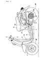
- FIG. 1 is a side elevational view of an embodiment of a hybrid vehicle to which the present invention is applied.
- the hybrid vehicle includes a front fork 1 for supporting a front wheel WF for rotation at a front portion of a vehicle body.
- the front fork 1 is supported for pivotal motion on a head pipe 2 and can be steered by an operation of a handlebar 3.
- a down pipe 4 is attached to the head pipe 2 and extends rearwardly and downwardly from the head pipe 2, and an intermediate frame 5 extends substantially horizontally from a lower end of the down pipe 4.
- a rear frame 6 is formed to extend rearwardly and upwardly from a rear end of the intermediate frame 5.
- a power unit 11 including a power source is mounted at one end thereof for pivotal motion on a vehicle body frame 10 configured in such a manner as described above.
- the power unit 11 has a rear wheel WR, which serves as a driving wheel, attached for rotation at the rear end thereof and is suspended by a rear cushion attached to the rear frame 6.
- An outer periphery of the vehicle body frame 10 is covered with a vehicle body cover 13, and a seat 14 for a rider is secured to a rear upper face of the vehicle body cover 13.
- a step floor 15 for receiving the feet of the rider is formed on the vehicle body frame 10 forwardly of the seat 14.
- An accommodation box 100 is provided below the seat 14 and functions as a utility space for accommodating a helmet or other baggage and so forth therein.
- FIG. 2 is a block diagram showing a system configuration of the hybrid vehicle described above.
- the power unit 11 includes an engine 20, an ACG starter motor 21a serving as an engine starter and a generator, and a continuously variable transmission (power transmission means) 23 connected to a crankshaft 22 for transmitting power from the engine 20 to the rear wheel WR.
- the power unit 11 further includes a variable-speed motor 77 for changing the transmission ratio of the continuously variable transmission 23, a starter clutch 40 for connecting or disconnecting the power transmission between the crankshaft 22 and an input power shaft of the continuously variable transmission 23, and a drive motor 21b which functions as a motor or a generator.
- the power unit 11 further includes a one-way clutch (one-way power transmission means) 44 which transmits power from the engine 20 and the drive motor 21b to the rear wheel WR side but does not transmit power from the rear wheel WR to the engine 20 side.
- the power unit 11 further includes a reduction gear 69 for transmitting the output power from the continuously variable transmission 23 at a reduced speed to the rear wheel WR.
- An engine rotational speed sensor 36 detects the rotational speed Ne of the engine 20.
- the power of the engine 20 is transmitted from the crankshaft 22 to the rear wheel WR through the starter clutch 40, continuously variable transmission 23, one-way clutch 44, drive shaft 60, and reduction gear 69.
- the power of the drive motor 21b is transmitted to the rear wheel WR through the drive shaft 60 and the reduction gear 69.
- the drive shaft 60 serves also as an output power shaft of the drive motor 21b.
- a battery 74 is connected to the ACG starter motor 21a and the drive motor 21b.
- the drive motor 21b functions as a motor and when the ACG starter motor 21a functions as a starter, the battery 74 supplies electric power to the motors 21a and 21b.
- the ACG starter motor 21a and the drive motor 21b function as generators, electric power generated by them is used to charge the battery 74.
- a throttle valve 17 for controlling the air amount is provided for pivotal motion in an intake pipe 16 of the engine 20.
- the throttle valve 17 is pivoted in response to an operation amount of a throttle grip (not shown) operated by the passenger.
- a DBW (Drive By Wire) system 12 is incorporated, and the throttle valve 17 can be automatically controlled based on the engine rotational speed, vehicle speed, or the like independently of an operation of the rider.
- An injector 18, which injects fuel, and a negative pressure sensor 19, which detects a negative pressure in the intake pipe, are disposed between the throttle valve 17 and the engine 20.
- a control unit 7 includes a target rotational speed determination section 7a for determining a target rotational speed of the engine when the power source is to be switched over from the drive motor 21b to the engine 20.
- the control unit 7 further includes an engine rotational speed control section 7b for controlling the engine rotational speed upon power switchover, and a transmission ratio control section 7c for controlling the transmission ratio of the continuously variable transmission 23 upon power switchover.
- the engine 20 includes a piston 25 connected to the crankshaft 22 through a connecting rod 24.
- the piston 25 is slidably movable in a cylinder 27 provided in a cylinder block 26, and the cylinder block 26 is disposed such that an axial line of the cylinder 27 extends substantially horizontally.
- a cylinder head 28 is secured to a front face of the cylinder block 26, and a combustion chamber 20a in which an air-fuel mixture is to be burnt is formed by the cylinder head 28, cylinder 27, and piston 25.
- a valve (not shown), which controls intake of air fuel mixture into the combustion chamber 20a or exhaust from the combustion chamber 20a, and an ignition plug 29 are disposed in the cylinder head 28. Opening and closing movement of the valve is controlled by rotation of a camshaft 30 supported for rotation on the cylinder head 28.
- the camshaft 30 includes a driven sprocket wheel 31 provided on one end side thereof, and an endless cam chain 33 extends between and around the driven sprocket wheel 31 and a driving sprocket wheel 32 provided at one end of the crankshaft 22.
- a water pump 34 for cooling the engine 20 is provided at one end of the camshaft 30. The water pump 34 is attached such that a rotary shaft 35 thereof rotates integrally with the camshaft 30. Accordingly, when the camshaft 30 rotates, the water pump 34 is operated.
- the crankshaft 22 is supported for rotation in a crankcase 48, a stator case 49 is connected to the right side of the crankcase 48 in a vehicle widthwise direction, and the ACG starter motor 21a is accommodated in the inside of the stator case 49.
- the ACG starter motor 21a is a motor of the so-called outer rotor type and includes teeth 50 secured to the stator case 49 and coils 51 formed from a conductor wound on the teeth 50.
- an outer rotor 52 is secured to the crankshaft 22 and has a substantially cylindrical shape which covers an outer periphery of the stator. Magnets 53 are disposed on an inner circumferential face of the outer rotor 52.
- a fan 54a for cooling the ACG starter motor 21a is attached to the outer rotor 52.
- cooling air is taken in through a cooling air inlet port formed in a side wall 55a of a cover 55 of the stator case 49.
- a transmission case 59 is connected to the left side of the crankcase 48 in the vehicle widthwise direction.
- a fan 54b secured to a left end portion of the crankshaft 22, the continuously variable transmission 23 whose driving side is connected to the crankshaft 22 through the starter clutch 40, and the drive motor 21b connected to the driven side of the continuously variable transmission 23 are accommodated in the transmission case 59.
- the fan 54b cools the continuously variable transmission 23 and the drive motor 21b accommodated in the transmission case 59 and is disposed on the same side as that of the drive motor 21b with respect to the continuously variable transmission 23, that is, in the present embodiment, on the left side in the vehicle widthwise direction.
- a cooling air inlet port 59a is formed on the front side and the left side of the vehicle body of the transmission case 59.
- the continuously variable transmission 23 is a belt converter including a driving side power transmission pulley 58, a driven side power transmission pulley 62, and an endless V belt 63 extending between and around the driving side power transmission pulley 58 and the driven side power transmission pulley 62.
- the driving side power transmission pulley 58 is mounted at a left end portion of the crankshaft 22, which projects in the vehicle widthwise direction from the crankcase 48, through the starter clutch 40.
- the driven side power transmission pulley 62 is mounted through the one-way clutch 44 on the drive shaft 60 supported for rotation in the transmission case 59 in such a manner as to have an axial line parallel to the crankshaft 22.
- the driving side power transmission pulley 58 is mounted for rotation in a circumferential direction with respect to the crankshaft 22 through a sleeve 58d as shown in an enlarged view of essential part of FIG. 4.
- the driving side power transmission pulley 58 includes a driving side fixed pulley half 58a securely mounted on the sleeve 58d, and a driving side movable pulley half 58c attached for sliding movement with respect to the sleeve 58d in its axial direction but against rotation in a circumferential direction.
- a speed change ring 57 is attached for rotation to the driving side movable pulley half 58c through a bearing 56.
- the speed change ring 57 has a gear 61 formed along a circumferential direction on a large diameter portion of an outer circumference thereof and has a trapezoidal screw thread 65 formed along an axial direction on an inner circumference thereof. Another trapezoidal screw thread 67 is held in meshing engagement with the trapezoidal screw thread 65.
- the trapezoidal screw thread 67 is attached to the sleeve 58d through a bearing 66 such that it can rotate in a circumferential direction but cannot slidably move in an axial direction.
- a worm wheel 75 is held in meshing engagement with the gear 61 of the speed change ring 57, and a worm gear 76 is held in meshing engagement with the worm wheel 75.
- the worm gear 76 is connected to a rotary shaft of the variable-speed motor 77 for controlling the transmission ratio.
- the driven side power transmission pulley 62 includes a driven side fixed pulley half 62a and a driven side movable pulley half 62b.
- the driven side fixed pulley half 62a is attached for rotation on the drive shaft 60 through a sleeve 62d such that it is held against sliding movement in the axial direction but can be rotated in a circumferential direction.
- the driven side movable pulley half 62b is attached for sliding movement in the axial direction on the sleeve 62d.
- a belt groove of a substantially V-shaped cross section is formed between the driving side fixed pulley half 58a and the driving side movable pulley half 58c and between the driven side fixed pulley half 62a and the driven side movable pulley half 62b.
- the endless V belt 63 extends between and around the belt grooves.
- a spring (resilient member) 64 is disposed on the rear face side (left side in the vehicle widthwise direction) of the driven side movable pulley half 62b.
- the spring 64 normally biases the driven side movable pulley half 62b toward the driven side fixed pulley half 62a.
- variable-speed motor 77 In order to vary the transmission ratio of the continuously variable transmission 23, the variable-speed motor 77 is driven in a direction corresponding to up/down of the transmission ratio. The driving force of the variable-speed motor 77 is transmitted to the gear 61 of the speed change ring 57 through the worm gear 76 and the worm wheel 75 to rotate the speed change ring 57.
- the speed change ring 57 Since the speed change ring 57 is held in meshing engagement with the sleeve 58d through the trapezoidal screws 65 and 67, if the direction of rotation is the shift up direction, then the speed change ring 57 moves in the leftward direction in the figure on the crankshaft 22, and thereupon, the driving side movable pulley half 58c slidably moves to the driving side fixed pulley half 58a side.
- the driving side movable pulley half 58c approaches the driving side fixed pulley half 58a by a distance of the sliding movement and the groove width of the driving side power transmission pulley 58 decreases.
- the contact position between the driving side power transmission pulley 58 and the V belt 63 is displaced to the outer side in a radial direction of the driving side power transmission pulley 58, and the wrapping diameter of the V belt 63 increases.
- the groove width formed by the driven side fixed pulley half 62a and the driven side movable pulley half 62b increases.
- the wrapping diameter (transmission pitch diameter) of the V belt 63 continuously varies to automatically and smoothly change the transmission ratio in response to the rotational speed of the crankshaft 22.
- the starter clutch 40 includes a cup-shaped outer case 40a securely mounted on the sleeve 58d, an outer plate 40b securely mounted at a left end portion of the crankshaft 22, a shoe 40d attached to an outer peripheral portion of the outer plate 40b through a weight 40c such that it is directed to the outer side in a radial direction, and a spring 40e for biasing the shoe 40d to the inner side in a radial direction.
- the power transmission between the crankshaft 22 and the continuously variable transmission 23 is interrupted by the starter clutch 40. If the engine rotational speed rises until the speed of rotation of the crankshaft 22 exceeds the predetermined value, then the centrifugal force acting upon the weight 40c exceeds the resilient force acting upon the inner side in a radial direction from the spring 40e. Consequently, the weight 40c moves to the outer side in the radial direction, and thereupon, the shoe 40d presses the inner circumferential face of the outer case 40a with force higher than a predetermined value. Consequently, rotation of the crankshaft 22 is transmitted to the sleeve 58d through the outer case 40a, and the driving side power transmission pulley 58 secured to the sleeve 58d is driven.
- a predetermined value for example, 3,000 rpm
- the one-way clutch 44 includes a cup-shaped outer clutch 44a, an inner clutch 44b fitted coaxially in the outer clutch 44a, and a roller 44c for allowing power to be transmitted only in one direction from the inner clutch 44b to the outer clutch 44a.
- the outer clutch 44a serves also an inner rotor 80 of the drive motor 21b and is formed from the same member as the inner rotor 80.
- the power from the engine 20 side transmitted to the driven side power transmission pulley 62 of the continuously variable transmission 23 is transmitted to the rear wheel WR through the driven side fixed pulley half 62a, inner clutch 44b, outer clutch 44a, that is, inner rotor body, drive shaft 60, and reduction gear 69.
- the power from the rear wheel WR side when the user walks and pushes the vehicle, upon regeneration operation and so forth is transmitted to the inner rotor body, that is, to the outer clutch 44a, through the reduction gear 69 and the drive shaft 60.
- the outer clutch 44a rotates but idly with respect to the inner clutch 44b, the power is not transmitted to the continuously variable transmission 23 or the engine 20.
- the drive motor 21b of the inner rotor type whose motor output power shaft is the drive shaft 60 is provided on the transmission case 59 on the rear side of the vehicle body.
- the inner rotor 80 includes the drive shaft 60, which is also the output power shaft of the continuously variable transmission 23, and the inner rotor body, that is, the inner clutch 44b, having a cup-like shape and coupled by spline coupling to the drive shaft 60 at a boss portion 80b formed at a central portion of the cup shape.
- a magnet is disposed on an outer peripheral face on the opening side of the inner clutch 44b.
- the reduction gear 69 is provided in a transmission chamber 70 connecting to the right side of a rear end portion of the transmission case 59 and includes an intermediate shaft 73 supported for rotation in parallel to the drive shaft 60 and an axle 68 of the rear wheel WR.
- the reduction gear 69 further includes a pair of first speed reducing gears 71, 71 and a pair of second speed reducing gears 72, 72.
- the gears 71, 71 are formed individually at a right end portion of the drive shaft 60 and a central portion of the intermediate shaft 73.
- the gears 72, 72 are formed individually at a right end portion of the intermediate shaft 73 and a left end portion of the axle 68.
- the ACG starter motor 21a on the crankshaft 22 is used to rotate the crankshaft 22.
- the starter clutch 40 is not in a connected state, and the power transmission from the crankshaft 22 to the continuously variable transmission 23 is interrupted.
- the throttle grip is operated in an opening direction, then in the present embodiment, only the drive motor 21b serves as the power source while the throttle opening ⁇ th is small. Since rotation of the drive shaft 60 by the drive motor 21b is not transmitted to the driven side power transmission pulley 62 through the one-way clutch 44, the continuously variable transmission 23 is not driven. Consequently, when only the drive motor 21b is used to drive the rear wheel WR to cause the vehicle to run, the energy transmission efficiency is improved.
- the throttle opening ⁇ th increases to raise the engine rotational speed until the speed of rotation of the crankshaft 22 exceeds a predetermined value (for example, 3000 rpm), then the rotating power of the crankshaft 22 is transmitted to the continuously variable transmission 23 through the starter clutch 40 and inputted to the one-way clutch 44.
- a predetermined value for example, 3000 rpm
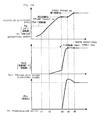
- FIG. 5 is a flow chart illustrating a procedure of the first embodiment of the power switchover method
- FIG. 6 is a timing chart of the procedure.
- the travelling state of the vehicle is determined based on results of detection of the vehicle speed V, engine rotational speed Ne, throttle opening ⁇ th, and so forth.
- a target engine rotational speed (target Ne) upon power switchover is calculated by the target rotational speed determination section 7a based on the vehicle speed V and the throttle opening ⁇ th at present.
- the engine rotational speed control section 7b is energized to start target Ne follow-up control of increasing or decreasing the throttle opening ⁇ th independently of the throttle operation by means of the DBW system 12 to raise the engine rotational speed to the target Ne.
- PID proportional-plus-integral
- the target Ne follow-up control is started at time t1 of FIG. 6 and the engine rotational speed Ne reaches a clutch-in speed of the starter clutch 40 at time t2, then the input power shaft (driving side power transmission pulley 58) of the continuously variable transmission 23 starts rotation, and also the rotational speed Np2 of the output power shaft (driven side pulley 62) begins to gradually rise in response to the starting of rotation.
- the rotational speed Np2 of the driven side power transmission pulley 62 is lower than the motor rotational speed Nm of the drive motor 21b and the one-way clutch 44 is in an idling state, the power is not transmitted between the drive motor 21b and the engine 20.
- the transmission ratio control section 7c is energized at step S6 to start transmission ratio raising control of raising the transmission ratio Rm by PID control based on the difference between the number of rotation of the drive shaft 60, that is, the motor rotational speed Nm, and the rotational speed Np2 of the driven side power transmission pulley 62.
- step S7 the motor rotational speed Nm of the drive motor 21b and the rotational speed Np2 of the driven side power transmission pulley 62 become equal to each other and the one-way clutch 44 is placed into a connected state.
- step S8 the transmission ratio raising control is stopped at step S8.
- step S9 normal control is entered and the power source is switched over from the drive motor 21b to the engine 20.
- FIG. 7 is a flow chart of a power switchover method according to a second embodiment of the present invention
- FIG. 8 is a timing chart of the power switching method.
- the traveling state of the vehicle is determined based on results of detection of the vehicle speed V, engine rotational speed Ne, throttle opening ⁇ th, and so forth.
- a target engine rotational speed (target Ne) upon power switchover is calculated by the target rotational speed determination section 7a based on the vehicle speed V and the throttle opening ⁇ th at present.
- the engine rotational speed control section 7b is energized to start target Ne follow-up control of increasing or decreasing the throttle opening ⁇ th independently of the throttle operation by means of the DBW system 12 to raise the engine rotational speed to the target Ne.
- PID control is adopted for the follow-up control.
- the target Ne follow-up control is started at time t1 of FIG. 8 and the engine rotational speed reaches a clutch-in speed of the starter clutch 40 at time t2, then the input power shaft (driving side power transmission pulley 58) of the continuously variable transmission starts rotation, and also the rotational speed Np2 of the output power shaft (driven side pulley 62) begins to gradually rise in response to the starting of rotation.
- the rotational speed Np2 of the driven side power transmission pulley 62 is lower than the motor rotational speed Nm of the drive motor 21b and the one-way clutch 44 is in an idling state, the power is not transmitted between the drive motor 21b and the engine 20.
- the transmission ratio control section 7c is energized at step S6a to start transmission ratio raising control of raising the transmission ratio by PID control based on the difference between the motor rotational speed Nm of the drive motor 21b and the rotational speed Np2 of the driven side power transmission pulley 62.
- the engine rotational speed Ne reaches the target Ne, and if this is detected at step S7a, then at step S8a, it is decided based on the motor rotational speed Nm of the drive motor 21b and the rotational speed Np2 of the driven side power transmission pulley 62 whether or not the one-way clutch 44 is connected.
- step S8a the motor rotational speed Nm of the drive motor 21b and the rotational speed Np2 of the driven side power transmission pulley 62 become equal to each other and the one-way clutch 44 is placed into a connected state.
- step S9a the transmission ratio raising control is stopped at step S9a.
- step S10a normal control is entered and the power source is switched over from the drive motor 21b to the engine 20.
- FIG. 9 is a flow chart of a power switchover method according to a third embodiment of the present invention
- FIG. 10 is a timing chart of the power switching method.
- the travelling state of the vehicle is determined based on results of detection of the vehicle speed V, engine rotational speed Ne, throttle opening ⁇ th, and so forth.
- a target engine rotational speed (first target Ne) upon power switchover is calculated by the target rotational speed determination section 7a based on the vehicle speed V and the throttle opening ⁇ th at present.
- a second target Ne a little lower than the first target Ne is calculated based on the vehicle speed V and the throttle opening ⁇ th at present similarly.
- the engine rotational speed control section 7b is energized to start target Ne follow-up control of increasing or decreasing the throttle opening ⁇ th independently of the throttle operation by means of the DBW system 12 to raise the engine rotational speed to the second target Ne.
- PID control is adopted for the follow-up control.
- the target Ne follow-up control is started at time t1 of FIG. 10 and the engine rotational speed reaches a connection speed of the starter clutch 40 at time t2, then the input power shaft (driving side power transmission pulley 58) of the continuously variable transmission starts rotation, and also the rotational speed Np2 of the output power shaft (driven side pulley 62) begins to gradually rise in response to the starting of rotation.
- the rotational speed Np2 of the driven side power transmission pulley 62 is lower than the motor rotational speed Nm of the drive motor 21b and the one-way clutch 44 is in an idling state, the power is not transmitted between the drive motor 21b and the engine 20.
- the transmission ratio control section 7c is energized at step S7b to start transmission ratio raising control of raising the transmission ratio by PID control based on the difference between the motor rotational speed Nm of the drive motor 21b and the rotational speed Np2 of the driven side power transmission pulley 62.
- the motor rotational speed Nm of the drive motor 21b and the rotational speed Np2 of the driven side power transmission pulley 62 become equal to each other and the one-way clutch 44 is placed into a connected state.
- the target value of the engine rotational speed in the target Ne follow-up control is changed from the second target value to the first target value.
- the transmission ratio Rm begins to decrease in response to the rise of the engine rotational speed Ne in order to make the motor rotational speed Nm of the drive motor 21b and the rotational speed Np2 of the driven side power transmission pulley 62 equal to each other.
- step S10b the engine rotational speed Ne reaches the first target Ne.
- step S11b normal control is entered at step S11b and the power source is switched over from the drive motor 21b to the engine 20.
- FIG. 11 is a flow chart of a power switchover method according to a fourth embodiment of the present invention
- FIG. 12 is a timing chart of the power switching method.
- the travelling state of the vehicle is determined based on results of detection of the vehicle speed V, engine rotational speed Ne, throttle opening ⁇ th, and so forth.
- a target engine rotational speed (first target Ne) upon power switchover is calculated by the target rotational speed determination section 7a based on the vehicle speed V and the throttle opening ⁇ th at present.
- a second target value a little lower than the first target Ne is calculated based on the vehicle speed V and the throttle opening ⁇ th at present similarly.
- the engine rotational speed control section 7b is energized to start target Ne follow-up control of increasing or decreasing the throttle opening ⁇ th independently of the throttle operation by means of the DBW system 12 to raise the engine rotational speed to the second target Ne.
- PID control is adopted for the follow-up control.
- the target Ne follow-up control is started at time t1 of FIG. 12 and the engine rotational speed reaches a connection speed of the starter clutch 40 at time t2, then the input power shaft (driving side power transmission pulley 58) of the continuously variable transmission 23 starts rotation, and also the rotational speed of the output power shaft (driven side pulley 62) begins to gradually rise in response to the starting of rotation.
- the rotational speed Np2 of the driven side power transmission pulley 62 is lower than the motor rotational speed Nm of the drive motor 21b and the one-way clutch 44 is in an idling state, the power is not transmitted between the drive motor 21b and the engine 20.
- the transmission ratio control section 7c is energized at step S7c to start transmission ratio raising control of raising the transmission ratio by PID control based on the difference between the motor rotational speed Nm of the drive motor 21b and the rotational speed Np2 of the driven side power transmission pulley 62.
- the engine rotational speed Ne reaches the second target Ne, and if this is detected at step S8c, then at step S9c, it is decided based on the motor rotational speed Nm of the drive motor 21b and the rotational speed Np2 of the driven side power transmission pulley 62 whether or not the one-way clutch 44 is connected.
- the motor rotational speed Nm of the drive motor 21b and the rotational speed Np2 of the driven side power transmission pulley 62 become equal to each other and the one-way clutch 44 is placed into a connected state.
- the target value of the engine rotational speed in the target Ne follow-up control is changed from the second target value to the first target value.
- the transmission ratio Rm begins to decrease in response to the rise of the engine rotational speed Ne in order to make the motor rotational speed Nm of the drive motor 21b and the rotational speed Np2 of the driven side power transmission pulley 62 equal to each other.
- step S11c normal control is entered at step S12c and the power source is switched over from the drive motor 21b to the engine 20.
Abstract
Description
- This invention relates to a power switchover apparatus for switching over the power source from a motor to an engine in a hybrid vehicle of the parallel type or the parallel and serial combined type wherein a drive shaft of the engine and a drive shaft of the motor are mechanically connected to each other.
- An electric automobile using a motor as a power source provides no atmospheric pollution and low noise pollution and is high in responsiveness in acceleration and deceleration when compared with a conventional automobile, which uses an engine as a power source. On the other hand, at present, the electric automobile is sometimes short in cruising distance as a result of limited battery capacity. Therefore, a hybrid vehicle, which uses a motor and an engine, has been put into practical use.
- As such hybrid vehicles, those of a "series hybrid type", a "parallel hybrid type", and a "series-parallel combined type" are generally known. The hybrid vehicle of the series hybrid type uses the motor as the power source and uses the engine as a power source for a generator for charging the battery. The hybrid vehicle of the parallel hybrid type uses the motor and the engine both as the power source for the vehicle and uses them in response to a travelling condition and so forth. The hybrid vehicle of the series-parallel combined type selectively uses the two types in response to a travelling situation.
- Since the motor is superior in low speed torque and is also superior in efficiency in a low speed region to the engine, a hybrid vehicle of the parallel hybrid type or the series-parallel combined type performs switchover control of the power source so that the motor is used as the power source in a low-speed region while the engine is used as the power source in a middle- or high-speed region.
- However, if the torque of the engine is added simply to the torque of the motor upon such power switchover, then the driving torque of the vehicle changes suddenly and a switchover shock occurs. Also, when the rotational speeds of the engine and the motor do not coincide with each other, the driving torque of the vehicle changes suddenly and a switchover shock occurs similarly.
- In order to reduce such a shock upon power switchover as just described, Japanese Patent Laid-Open No. 2000-23311 discloses a technique where an electromagnetic powder clutch is interposed between an engine and a drive motor and, when the power source is to be switched over, the output power of the motor is controlled so that the rotational speeds and the output torques of the engine and the drive motor may coincide with each other. Then, at a point of time when the rotational speeds and the output torques become coincident with each other, excitation current is supplied to the clutch to establish connection of the engine and the drive motor.
- According to the background art described above, it is necessary to provide an electromagnetic clutch between the engine and the drive motor, and it is necessary to provide a feed line for supplying excitation current to the electromagnetic clutch and a control apparatus for controlling the excitation current. Therefore, in the background art described above, the configuration is complicated and increase of weight is invited.
- It is an object of the present invention to provide a power switchover apparatus for a hybrid vehicle avoiding the problems of the background art described above and which can perform power switchover smoothly with a configuration which is simple and results in only a small increase in weight.
- According to the present invention, there is provided a power switchover apparatus for a hybrid vehicle having a starting clutch provided between a crankshaft of an engine and an automatic transmission, a one-way clutch interposed between said automatic transmission and a drive shaft, and a drive motor connected to said drive shaft, wherein, upon starting, said one-way clutch is controlled to idle using said motor as a power source, and thereafter, said one-way clutch is connected to switch over the power source to said engine, said power switchover apparatus for a hybrid vehicle comprising: target rotational speed setting means for setting a target rotational speed of said engine when the power source is to be switched over from said motor to said engine; and control means for controlling the engine rotational speed and the transmission ratio of said automatic transmission in response to the target rotational speed; said control means including: means for controlling the engine rotational speed to follow up the target rotational speed; and means for controlling the transmission ratio of said automatic transmission to rise until the power of said engine is transmitted to said drive shaft while the engine rotational speed remains following up the target rotational speed.
- When the power source is switched over from the drive motor to the engine, only the transmission ratio of the automatic transmission is controlled to transmit the power of the engine to the drive shaft while the engine rotational speed is maintained fixed. Therefore, the influence of the inertial mass around the engine can be reduced.
- In a preferred form, the target rotational speed setting means sets a first target rotational speed of the engine to be used when the power source is to be switched over from the motor to the engine and a second target rotational speed lower than the first target rotational speed. The control means controls the engine rotational speed to follow up the second target rotational speed, controls the transmission ratio of the automatic transmission to rise until the power of the engine is transmitted to the drive shaft while the control means controls the engine rotational speed to remain following up the second target rotational speed, and controls the transmission ratio of the automatic transmission so that, after the power of the engine is transmitted to the drive shaft, the engine rotational speed is controlled to follow up the first target value, and the rotational speed of the drive shaft is kept fixed irrespective of the rise of the engine rotational speed.
- In this preferred form, since the second target rotational speed is set lower than the first rotational speed, the transmission ratio of the automatic transmission can be raised steeply. As a result, the time required for the power switchover can be shortened.
- In a further preferred form, the means for raising the transmission ratio of the automatic transmission causes the transmission ratio to be raised after the one-way clutch is placed into a connected state.
- Since the power source is switched over after the connection of the one-way clutch is completed, smooth power switchover can be achieved.
- Preferably, the means for raising the transmission ratio of the automatic transmission decides disconnection or connection of the one-way clutch based on a difference in rotational speed between an output power shaft of the automatic transmission and the drive shaft. The connection or disconnection state of the one-way clutch can thus be detected simply.
- In an alternative preferred form, the means for raising the transmission ratio of the automatic transmission starts to raise the transmission ratio when the engine rotational speed reaches the target rotational speed.
- In this preferred form, since the raising of the transmission ratio is started after the engine rotational speed reaches the target rotational speed, the power source can be switched over in a state wherein it is certain that the engine rotational speed is maintained at the target rotational speed.
- In a further alternative preferred form, the means for raising the transmission ratio of the automatic transmission starts to raise the transmission ratio when the starting clutch is connected. If the starting clutch is connected, then the raising of the transmission ratio is started even before the engine rotational speed reaches the target rotational speed. Consequently, the time required for power switchover can be shortened.
- Preferred embodiments of the present invention will now be described in detail by way example only with reference to the accompanying drawings, in which:
- FIG. 1 is a side elevational view of a motorcycle according to an embodiment of a hybrid vehicle according to the present invention;
- FIG. 2 is a block diagram showing a system configuration of the motorcycle shown in FIG. 1;
- FIG. 3 is a sectional view of a power unit of the motorcycle shown in FIG. 1;
- FIG. 4 is an enlarged view of essential part of FIG. 3;
- FIG. 5 is a flow chart illustrating a procedure of a first embodiment of a power switchover method;
- FIG. 6 is a timing chart of the first embodiment of the power switchover method;
- FIG. 7 is a flow chart illustrating a procedure of a second embodiment of the power switchover method;
- FIG. 8 is a timing chart of the second embodiment of the power switchover method;
- FIG. 9 is a flow chart illustrating a procedure of a third embodiment of the power switchover method;
- FIG. 10 is a timing chart of the third embodiment of the power switchover method;
- FIG. 11 is a flow chart illustrating a procedure of a fourth embodiment of the power switchover method; and
- FIG. 12 is a timing chart of the fourth embodiment of the power switchover method.
- As mentioned above, FIG. 1 is a side elevational view of an embodiment of a hybrid vehicle to which the present invention is applied.
- The hybrid vehicle includes a
front fork 1 for supporting a front wheel WF for rotation at a front portion of a vehicle body. Thefront fork 1 is supported for pivotal motion on ahead pipe 2 and can be steered by an operation of ahandlebar 3. A down pipe 4 is attached to thehead pipe 2 and extends rearwardly and downwardly from thehead pipe 2, and anintermediate frame 5 extends substantially horizontally from a lower end of the down pipe 4. Further, a rear frame 6 is formed to extend rearwardly and upwardly from a rear end of theintermediate frame 5. - A
power unit 11 including a power source is mounted at one end thereof for pivotal motion on avehicle body frame 10 configured in such a manner as described above. Thepower unit 11 has a rear wheel WR, which serves as a driving wheel, attached for rotation at the rear end thereof and is suspended by a rear cushion attached to the rear frame 6. - An outer periphery of the
vehicle body frame 10 is covered with avehicle body cover 13, and aseat 14 for a rider is secured to a rear upper face of thevehicle body cover 13. Astep floor 15 for receiving the feet of the rider is formed on thevehicle body frame 10 forwardly of theseat 14. Anaccommodation box 100 is provided below theseat 14 and functions as a utility space for accommodating a helmet or other baggage and so forth therein. - FIG. 2 is a block diagram showing a system configuration of the hybrid vehicle described above. The
power unit 11 includes anengine 20, an ACGstarter motor 21a serving as an engine starter and a generator, and a continuously variable transmission (power transmission means) 23 connected to acrankshaft 22 for transmitting power from theengine 20 to the rear wheel WR. Thepower unit 11 further includes a variable-speed motor 77 for changing the transmission ratio of the continuouslyvariable transmission 23, astarter clutch 40 for connecting or disconnecting the power transmission between thecrankshaft 22 and an input power shaft of the continuouslyvariable transmission 23, and adrive motor 21b which functions as a motor or a generator. Thepower unit 11 further includes a one-way clutch (one-way power transmission means) 44 which transmits power from theengine 20 and thedrive motor 21b to the rear wheel WR side but does not transmit power from the rear wheel WR to theengine 20 side. Thepower unit 11 further includes areduction gear 69 for transmitting the output power from the continuouslyvariable transmission 23 at a reduced speed to the rear wheel WR. An enginerotational speed sensor 36 detects the rotational speed Ne of theengine 20. - The power of the
engine 20 is transmitted from thecrankshaft 22 to the rear wheel WR through thestarter clutch 40, continuouslyvariable transmission 23, one-way clutch 44,drive shaft 60, andreduction gear 69. On the other hand, the power of thedrive motor 21b is transmitted to the rear wheel WR through thedrive shaft 60 and thereduction gear 69. In short, in the present embodiment, thedrive shaft 60 serves also as an output power shaft of thedrive motor 21b. - A
battery 74 is connected to the ACGstarter motor 21a and thedrive motor 21b. When thedrive motor 21b functions as a motor and when theACG starter motor 21a functions as a starter, thebattery 74 supplies electric power to themotors ACG starter motor 21a and thedrive motor 21b function as generators, electric power generated by them is used to charge thebattery 74. - A
throttle valve 17 for controlling the air amount is provided for pivotal motion in anintake pipe 16 of theengine 20. Thethrottle valve 17 is pivoted in response to an operation amount of a throttle grip (not shown) operated by the passenger. It is to be noted that, in the present embodiment, a DBW (Drive By Wire)system 12 is incorporated, and thethrottle valve 17 can be automatically controlled based on the engine rotational speed, vehicle speed, or the like independently of an operation of the rider. Aninjector 18, which injects fuel, and anegative pressure sensor 19, which detects a negative pressure in the intake pipe, are disposed between thethrottle valve 17 and theengine 20. - A
control unit 7 includes a target rotationalspeed determination section 7a for determining a target rotational speed of the engine when the power source is to be switched over from thedrive motor 21b to theengine 20. Thecontrol unit 7 further includes an engine rotationalspeed control section 7b for controlling the engine rotational speed upon power switchover, and a transmissionratio control section 7c for controlling the transmission ratio of the continuouslyvariable transmission 23 upon power switchover. - Now, a configuration of the
power unit 11 including theengine 20 and thedrive motor 21b is described with reference to FIG. 3. - The
engine 20 includes apiston 25 connected to thecrankshaft 22 through a connectingrod 24. Thepiston 25 is slidably movable in acylinder 27 provided in acylinder block 26, and thecylinder block 26 is disposed such that an axial line of thecylinder 27 extends substantially horizontally. Acylinder head 28 is secured to a front face of thecylinder block 26, and acombustion chamber 20a in which an air-fuel mixture is to be burnt is formed by thecylinder head 28,cylinder 27, andpiston 25. - A valve (not shown), which controls intake of air fuel mixture into the
combustion chamber 20a or exhaust from thecombustion chamber 20a, and anignition plug 29 are disposed in thecylinder head 28. Opening and closing movement of the valve is controlled by rotation of acamshaft 30 supported for rotation on thecylinder head 28. Thecamshaft 30 includes a drivensprocket wheel 31 provided on one end side thereof, and anendless cam chain 33 extends between and around the drivensprocket wheel 31 and a drivingsprocket wheel 32 provided at one end of thecrankshaft 22. A water pump 34 for cooling theengine 20 is provided at one end of thecamshaft 30. The water pump 34 is attached such that arotary shaft 35 thereof rotates integrally with thecamshaft 30. Accordingly, when thecamshaft 30 rotates, the water pump 34 is operated. - The
crankshaft 22 is supported for rotation in acrankcase 48, astator case 49 is connected to the right side of thecrankcase 48 in a vehicle widthwise direction, and theACG starter motor 21a is accommodated in the inside of thestator case 49. TheACG starter motor 21a is a motor of the so-called outer rotor type and includesteeth 50 secured to thestator case 49 and coils 51 formed from a conductor wound on theteeth 50. Meanwhile, anouter rotor 52 is secured to thecrankshaft 22 and has a substantially cylindrical shape which covers an outer periphery of the stator.Magnets 53 are disposed on an inner circumferential face of theouter rotor 52. - A
fan 54a for cooling theACG starter motor 21a is attached to theouter rotor 52. When thefan 54a rotates in synchronism with thecrankshaft 22, cooling air is taken in through a cooling air inlet port formed in aside wall 55a of acover 55 of thestator case 49. - A transmission case 59 is connected to the left side of the
crankcase 48 in the vehicle widthwise direction. Afan 54b secured to a left end portion of thecrankshaft 22, the continuouslyvariable transmission 23 whose driving side is connected to thecrankshaft 22 through thestarter clutch 40, and thedrive motor 21b connected to the driven side of the continuouslyvariable transmission 23 are accommodated in the transmission case 59. Thefan 54b cools the continuouslyvariable transmission 23 and thedrive motor 21b accommodated in the transmission case 59 and is disposed on the same side as that of thedrive motor 21b with respect to the continuouslyvariable transmission 23, that is, in the present embodiment, on the left side in the vehicle widthwise direction. - A cooling air inlet port 59a is formed on the front side and the left side of the vehicle body of the transmission case 59. When the
fan 54b rotates in synchronism with thecrankshaft 22, external air is taken into the transmission case 59 through the cooling air inlet port 59a positioned in the proximity of thefan 54b and thedrive motor 21b and the continuouslyvariable transmission 23 are cooled by the external air. - The continuously
variable transmission 23 is a belt converter including a driving sidepower transmission pulley 58, a driven sidepower transmission pulley 62, and anendless V belt 63 extending between and around the driving sidepower transmission pulley 58 and the driven sidepower transmission pulley 62. The driving sidepower transmission pulley 58 is mounted at a left end portion of thecrankshaft 22, which projects in the vehicle widthwise direction from thecrankcase 48, through thestarter clutch 40. The driven sidepower transmission pulley 62 is mounted through the one-way clutch 44 on thedrive shaft 60 supported for rotation in the transmission case 59 in such a manner as to have an axial line parallel to thecrankshaft 22. - The driving side
power transmission pulley 58 is mounted for rotation in a circumferential direction with respect to thecrankshaft 22 through asleeve 58d as shown in an enlarged view of essential part of FIG. 4. The driving sidepower transmission pulley 58 includes a driving side fixed pulley half 58a securely mounted on thesleeve 58d, and a driving sidemovable pulley half 58c attached for sliding movement with respect to thesleeve 58d in its axial direction but against rotation in a circumferential direction. Aspeed change ring 57 is attached for rotation to the driving sidemovable pulley half 58c through abearing 56. - The
speed change ring 57 has agear 61 formed along a circumferential direction on a large diameter portion of an outer circumference thereof and has atrapezoidal screw thread 65 formed along an axial direction on an inner circumference thereof. Anothertrapezoidal screw thread 67 is held in meshing engagement with thetrapezoidal screw thread 65. Thetrapezoidal screw thread 67 is attached to thesleeve 58d through abearing 66 such that it can rotate in a circumferential direction but cannot slidably move in an axial direction. Aworm wheel 75 is held in meshing engagement with thegear 61 of thespeed change ring 57, and aworm gear 76 is held in meshing engagement with theworm wheel 75. Theworm gear 76 is connected to a rotary shaft of the variable-speed motor 77 for controlling the transmission ratio. - On the other hand, the driven side
power transmission pulley 62 includes a driven side fixedpulley half 62a and a driven sidemovable pulley half 62b. The driven side fixedpulley half 62a is attached for rotation on thedrive shaft 60 through asleeve 62d such that it is held against sliding movement in the axial direction but can be rotated in a circumferential direction. The driven sidemovable pulley half 62b is attached for sliding movement in the axial direction on thesleeve 62d. - A belt groove of a substantially V-shaped cross section is formed between the driving side fixed pulley half 58a and the driving side
movable pulley half 58c and between the driven side fixedpulley half 62a and the driven sidemovable pulley half 62b. Theendless V belt 63 extends between and around the belt grooves. - A spring (resilient member) 64 is disposed on the rear face side (left side in the vehicle widthwise direction) of the driven side
movable pulley half 62b. Thespring 64 normally biases the driven side movable pulley half 62b toward the driven side fixedpulley half 62a. - In order to vary the transmission ratio of the continuously
variable transmission 23, the variable-speed motor 77 is driven in a direction corresponding to up/down of the transmission ratio. The driving force of the variable-speed motor 77 is transmitted to thegear 61 of thespeed change ring 57 through theworm gear 76 and theworm wheel 75 to rotate thespeed change ring 57. Since thespeed change ring 57 is held in meshing engagement with thesleeve 58d through the trapezoidal screws 65 and 67, if the direction of rotation is the shift up direction, then thespeed change ring 57 moves in the leftward direction in the figure on thecrankshaft 22, and thereupon, the driving sidemovable pulley half 58c slidably moves to the driving side fixed pulley half 58a side. The driving sidemovable pulley half 58c approaches the driving side fixed pulley half 58a by a distance of the sliding movement and the groove width of the driving sidepower transmission pulley 58 decreases. Consequently, the contact position between the driving sidepower transmission pulley 58 and theV belt 63 is displaced to the outer side in a radial direction of the driving sidepower transmission pulley 58, and the wrapping diameter of theV belt 63 increases. Thereupon, in the driven sidepower transmission pulley 62, the groove width formed by the driven side fixedpulley half 62a and the driven sidemovable pulley half 62b increases. In short, the wrapping diameter (transmission pitch diameter) of theV belt 63 continuously varies to automatically and smoothly change the transmission ratio in response to the rotational speed of thecrankshaft 22. - The
starter clutch 40 includes a cup-shaped outer case 40a securely mounted on thesleeve 58d, anouter plate 40b securely mounted at a left end portion of thecrankshaft 22, ashoe 40d attached to an outer peripheral portion of theouter plate 40b through aweight 40c such that it is directed to the outer side in a radial direction, and aspring 40e for biasing theshoe 40d to the inner side in a radial direction. - When the engine rotational speed, that is, the speed of rotation of the
crankshaft 22, is equal to or lower than a predetermined value (for example, 3,000 rpm), the power transmission between thecrankshaft 22 and the continuouslyvariable transmission 23 is interrupted by thestarter clutch 40. If the engine rotational speed rises until the speed of rotation of thecrankshaft 22 exceeds the predetermined value, then the centrifugal force acting upon theweight 40c exceeds the resilient force acting upon the inner side in a radial direction from thespring 40e. Consequently, theweight 40c moves to the outer side in the radial direction, and thereupon, theshoe 40d presses the inner circumferential face of the outer case 40a with force higher than a predetermined value. Consequently, rotation of thecrankshaft 22 is transmitted to thesleeve 58d through the outer case 40a, and the driving sidepower transmission pulley 58 secured to thesleeve 58d is driven. - The one-way clutch 44 includes a cup-shaped outer clutch 44a, an inner clutch 44b fitted coaxially in the outer clutch 44a, and a roller 44c for allowing power to be transmitted only in one direction from the inner clutch 44b to the outer clutch 44a. The outer clutch 44a serves also an
inner rotor 80 of thedrive motor 21b and is formed from the same member as theinner rotor 80. - The power from the
engine 20 side transmitted to the driven sidepower transmission pulley 62 of the continuouslyvariable transmission 23 is transmitted to the rear wheel WR through the driven side fixedpulley half 62a, inner clutch 44b, outer clutch 44a, that is, inner rotor body, driveshaft 60, andreduction gear 69. On the other hand, the power from the rear wheel WR side when the user walks and pushes the vehicle, upon regeneration operation and so forth, is transmitted to the inner rotor body, that is, to the outer clutch 44a, through thereduction gear 69 and thedrive shaft 60. However, since the outer clutch 44a rotates but idly with respect to the inner clutch 44b, the power is not transmitted to the continuouslyvariable transmission 23 or theengine 20. - The
drive motor 21b of the inner rotor type whose motor output power shaft is thedrive shaft 60 is provided on the transmission case 59 on the rear side of the vehicle body. Theinner rotor 80 includes thedrive shaft 60, which is also the output power shaft of the continuouslyvariable transmission 23, and the inner rotor body, that is, the inner clutch 44b, having a cup-like shape and coupled by spline coupling to thedrive shaft 60 at a boss portion 80b formed at a central portion of the cup shape. A magnet is disposed on an outer peripheral face on the opening side of the inner clutch 44b. - Referring back to FIG. 3, the
reduction gear 69 is provided in atransmission chamber 70 connecting to the right side of a rear end portion of the transmission case 59 and includes anintermediate shaft 73 supported for rotation in parallel to thedrive shaft 60 and anaxle 68 of the rear wheel WR. Thereduction gear 69 further includes a pair of first speed reducing gears 71, 71 and a pair of secondspeed reducing gears drive shaft 60 and a central portion of theintermediate shaft 73. Thegears intermediate shaft 73 and a left end portion of theaxle 68. Through the configuration, rotation of thedrive shaft 60 is decreased at a predetermined reduction ratio and transmitted to theaxle 68 of the rear wheel WR supported for rotation in parallel to thedrive shaft 60. - In the hybrid vehicle having the configuration described above, upon starting of the engine, the
ACG starter motor 21a on thecrankshaft 22 is used to rotate thecrankshaft 22. Thereupon, thestarter clutch 40 is not in a connected state, and the power transmission from thecrankshaft 22 to the continuouslyvariable transmission 23 is interrupted. - If the throttle grip is operated in an opening direction, then in the present embodiment, only the
drive motor 21b serves as the power source while the throttle opening θth is small. Since rotation of thedrive shaft 60 by thedrive motor 21b is not transmitted to the driven sidepower transmission pulley 62 through the one-way clutch 44, the continuouslyvariable transmission 23 is not driven. Consequently, when only thedrive motor 21b is used to drive the rear wheel WR to cause the vehicle to run, the energy transmission efficiency is improved. - If the throttle opening θth increases to raise the engine rotational speed until the speed of rotation of the
crankshaft 22 exceeds a predetermined value (for example, 3000 rpm), then the rotating power of thecrankshaft 22 is transmitted to the continuouslyvariable transmission 23 through thestarter clutch 40 and inputted to the one-way clutch 44. When the speed of rotation of the input side of the one-way clutch 44 and the speed of rotation of the output side of the one-way clutch 44, that is, thedrive shaft 60, coincide with each other, then the power source is switched over from thedrive motor 21b to theengine 20. - FIG. 5 is a flow chart illustrating a procedure of the first embodiment of the power switchover method, and FIG. 6 is a timing chart of the procedure.
- At step S1, the travelling state of the vehicle is determined based on results of detection of the vehicle speed V, engine rotational speed Ne, throttle opening θth, and so forth. At step S2, it is determined based on the traveling state whether or not a power switchover condition for switching over the power source from the
drive motor 21b to theengine 20 is satisfied. If such a power switchover condition that the throttle opening θth is higher than a reference opening and the vehicle speed V and the engine rotational speed Ne exhibit an increasing tendency is satisfied, then the processing advances to step S3. - At step S3, a target engine rotational speed (target Ne) upon power switchover is calculated by the target rotational
speed determination section 7a based on the vehicle speed V and the throttle opening θth at present. At step S4, the engine rotationalspeed control section 7b is energized to start target Ne follow-up control of increasing or decreasing the throttle opening θth independently of the throttle operation by means of theDBW system 12 to raise the engine rotational speed to the target Ne. For the follow-up control, PID (proportional-plus-integral) control is adopted. - If the target Ne follow-up control is started at time t1 of FIG. 6 and the engine rotational speed Ne reaches a clutch-in speed of the
starter clutch 40 at time t2, then the input power shaft (driving side power transmission pulley 58) of the continuouslyvariable transmission 23 starts rotation, and also the rotational speed Np2 of the output power shaft (driven side pulley 62) begins to gradually rise in response to the starting of rotation. However, at this point of time, since the rotational speed Np2 of the driven sidepower transmission pulley 62 is lower than the motor rotational speed Nm of thedrive motor 21b and the one-way clutch 44 is in an idling state, the power is not transmitted between thedrive motor 21b and theengine 20. - At time t3, the engine rotational speed Ne reaches the target Ne, and if this is detected at step S5, then the transmission
ratio control section 7c is energized at step S6 to start transmission ratio raising control of raising the transmission ratio Rm by PID control based on the difference between the number of rotation of thedrive shaft 60, that is, the motor rotational speed Nm, and the rotational speed Np2 of the driven sidepower transmission pulley 62. - At time t4, the motor rotational speed Nm of the
drive motor 21b and the rotational speed Np2 of the driven sidepower transmission pulley 62 become equal to each other and the one-way clutch 44 is placed into a connected state. When this is detected at step S7, the transmission ratio raising control is stopped at step S8. At step S9, normal control is entered and the power source is switched over from thedrive motor 21b to theengine 20. - FIG. 7 is a flow chart of a power switchover method according to a second embodiment of the present invention, and FIG. 8 is a timing chart of the power switching method.
- At step S1, the traveling state of the vehicle is determined based on results of detection of the vehicle speed V, engine rotational speed Ne, throttle opening θth, and so forth. At step S2, it is determined based on the traveling state whether or not a power switchover condition for switching over the power source from the
drive motor 21b to theengine 20 is satisfied. If such a power switchover condition that the throttle opening θth is higher than a reference opening and the vehicle speed V and the engine rotational speed Ne exhibit an increasing tendency is satisfied, then the processing advances to step S3. - At step S3, a target engine rotational speed (target Ne) upon power switchover is calculated by the target rotational
speed determination section 7a based on the vehicle speed V and the throttle opening θth at present. At step S4, the engine rotationalspeed control section 7b is energized to start target Ne follow-up control of increasing or decreasing the throttle opening θth independently of the throttle operation by means of theDBW system 12 to raise the engine rotational speed to the target Ne. For the follow-up control, PID control is adopted. - If the target Ne follow-up control is started at time t1 of FIG. 8 and the engine rotational speed reaches a clutch-in speed of the
starter clutch 40 at time t2, then the input power shaft (driving side power transmission pulley 58) of the continuously variable transmission starts rotation, and also the rotational speed Np2 of the output power shaft (driven side pulley 62) begins to gradually rise in response to the starting of rotation. However, at this point of time, since the rotational speed Np2 of the driven sidepower transmission pulley 62 is lower than the motor rotational speed Nm of thedrive motor 21b and the one-way clutch 44 is in an idling state, the power is not transmitted between thedrive motor 21b and theengine 20. - When the clutch-in of the
starter clutch 40 is detected at step S5a, the transmissionratio control section 7c is energized at step S6a to start transmission ratio raising control of raising the transmission ratio by PID control based on the difference between the motor rotational speed Nm of thedrive motor 21b and the rotational speed Np2 of the driven sidepower transmission pulley 62. At time t3, the engine rotational speed Ne reaches the target Ne, and if this is detected at step S7a, then at step S8a, it is decided based on the motor rotational speed Nm of thedrive motor 21b and the rotational speed Np2 of the driven sidepower transmission pulley 62 whether or not the one-way clutch 44 is connected. - At time t4, the motor rotational speed Nm of the
drive motor 21b and the rotational speed Np2 of the driven sidepower transmission pulley 62 become equal to each other and the one-way clutch 44 is placed into a connected state. When this is detected at step S8a, the transmission ratio raising control is stopped at step S9a. At step S10a, normal control is entered and the power source is switched over from thedrive motor 21b to theengine 20. - FIG. 9 is a flow chart of a power switchover method according to a third embodiment of the present invention, and FIG. 10 is a timing chart of the power switching method.
- At step S1, the travelling state of the vehicle is determined based on results of detection of the vehicle speed V, engine rotational speed Ne, throttle opening θth, and so forth. At step S2, it is determined based on the travelling state whether or not a power switchover condition for switching over the power source from the
drive motor 21b to theengine 20 is satisfied. If such a power switchover condition that the throttle opening θth is higher than a reference opening and the vehicle speed V and the engine rotational speed Ne exhibit an increasing tendency is satisfied, then the processing advances to step S3b. - At step S3b, a target engine rotational speed (first target Ne) upon power switchover is calculated by the target rotational
speed determination section 7a based on the vehicle speed V and the throttle opening θth at present. At step S4b, a second target Ne a little lower than the first target Ne is calculated based on the vehicle speed V and the throttle opening θth at present similarly. At step S5b, the engine rotationalspeed control section 7b is energized to start target Ne follow-up control of increasing or decreasing the throttle opening θth independently of the throttle operation by means of theDBW system 12 to raise the engine rotational speed to the second target Ne. For the follow-up control, PID control is adopted. - If the target Ne follow-up control is started at time t1 of FIG. 10 and the engine rotational speed reaches a connection speed of the
starter clutch 40 at time t2, then the input power shaft (driving side power transmission pulley 58) of the continuously variable transmission starts rotation, and also the rotational speed Np2 of the output power shaft (driven side pulley 62) begins to gradually rise in response to the starting of rotation. However, at this point of time, since the rotational speed Np2 of the driven sidepower transmission pulley 62 is lower than the motor rotational speed Nm of thedrive motor 21b and the one-way clutch 44 is in an idling state, the power is not transmitted between thedrive motor 21b and theengine 20. - At time t3, the engine rotational speed Ne reaches the second target Ne, and when this is detected at step S6b, the transmission
ratio control section 7c is energized at step S7b to start transmission ratio raising control of raising the transmission ratio by PID control based on the difference between the motor rotational speed Nm of thedrive motor 21b and the rotational speed Np2 of the driven sidepower transmission pulley 62. - At time t4, the motor rotational speed Nm of the
drive motor 21b and the rotational speed Np2 of the driven sidepower transmission pulley 62 become equal to each other and the one-way clutch 44 is placed into a connected state. When this is detected at step S8b, at step S9b, the target value of the engine rotational speed in the target Ne follow-up control is changed from the second target value to the first target value. After the engine rotational speed Ne begins to rise, the transmission ratio Rm begins to decrease in response to the rise of the engine rotational speed Ne in order to make the motor rotational speed Nm of thedrive motor 21b and the rotational speed Np2 of the driven sidepower transmission pulley 62 equal to each other. - At time t5, the engine rotational speed Ne reaches the first target Ne. When this is detected at step S10b, normal control is entered at step S11b and the power source is switched over from the
drive motor 21b to theengine 20. - FIG. 11 is a flow chart of a power switchover method according to a fourth embodiment of the present invention, and FIG. 12 is a timing chart of the power switching method.
- At step S1, the travelling state of the vehicle is determined based on results of detection of the vehicle speed V, engine rotational speed Ne, throttle opening θth, and so forth. At step S2, it is determined based on the travelling state whether or not a power switchover condition for switching over the power source from the
drive motor 21b to theengine 20 is satisfied. If such a power switchover condition that the throttle opening θth is higher than a reference opening and the vehicle speed V and the engine rotational speed Ne exhibit an increasing tendency is satisfied, then the processing advances to step S3c. - At step S3c, a target engine rotational speed (first target Ne) upon power switchover is calculated by the target rotational
speed determination section 7a based on the vehicle speed V and the throttle opening θth at present. At step S4c, a second target value a little lower than the first target Ne is calculated based on the vehicle speed V and the throttle opening θth at present similarly. At step S5c, the engine rotationalspeed control section 7b is energized to start target Ne follow-up control of increasing or decreasing the throttle opening θth independently of the throttle operation by means of theDBW system 12 to raise the engine rotational speed to the second target Ne. For the follow-up control, PID control is adopted. - If the target Ne follow-up control is started at time t1 of FIG. 12 and the engine rotational speed reaches a connection speed of the
starter clutch 40 at time t2, then the input power shaft (driving side power transmission pulley 58) of the continuouslyvariable transmission 23 starts rotation, and also the rotational speed of the output power shaft (driven side pulley 62) begins to gradually rise in response to the starting of rotation. However, at this point of time, since the rotational speed Np2 of the driven sidepower transmission pulley 62 is lower than the motor rotational speed Nm of thedrive motor 21b and the one-way clutch 44 is in an idling state, the power is not transmitted between thedrive motor 21b and theengine 20. - When the clutch-in of the
starter clutch 40 is detected at step S6c, the transmissionratio control section 7c is energized at step S7c to start transmission ratio raising control of raising the transmission ratio by PID control based on the difference between the motor rotational speed Nm of thedrive motor 21b and the rotational speed Np2 of the driven sidepower transmission pulley 62. At time t3, the engine rotational speed Ne reaches the second target Ne, and if this is detected at step S8c, then at step S9c, it is decided based on the motor rotational speed Nm of thedrive motor 21b and the rotational speed Np2 of the driven sidepower transmission pulley 62 whether or not the one-way clutch 44 is connected. - At time t4, the motor rotational speed Nm of the
drive motor 21b and the rotational speed Np2 of the driven sidepower transmission pulley 62 become equal to each other and the one-way clutch 44 is placed into a connected state. When this is detected at step S9c, at step S10c, the target value of the engine rotational speed in the target Ne follow-up control is changed from the second target value to the first target value. After the engine rotational speed Ne begins to rise, the transmission ratio Rm begins to decrease in response to the rise of the engine rotational speed Ne in order to make the motor rotational speed Nm of thedrive motor 21b and the rotational speed Np2 of the driven sidepower transmission pulley 62 equal to each other. - At time t5, the engine rotational speed Ne reaches the first target Ne. When this is detected at step S11c, normal control is entered at step S12c and the power source is switched over from the
drive motor 21b to theengine 20.
Claims (7)
- A power switchover apparatus for a hybrid vehicle having a starting clutch provided between a crankshaft of an engine and an automatic transmission, a one-way clutch interposed between said automatic transmission and a drive shaft, and a drive motor connected to said drive shaft,
wherein, upon starting, said one-way clutch is controlled to idle using said motor as a power source, and thereafter, said one-way clutch is connected to switch over the power source to said engine, said power switchover apparatus for a hybrid vehicle comprising:target rotational speed setting means for setting a target rotational speed of said engine when the power source is to be switched over from said motor to said engine; andcontrol means for controlling the engine rotational speed and the transmission ratio of said automatic transmission in response to the target rotational speed;said control means including:means for controlling the engine rotational speed to follow up the target rotational speed; andmeans for controlling the transmission ratio of said automatic transmission to rise until the power of said engine is transmitted to said drive shaft while the engine rotational speed remains following up the target rotational speed. - A power switchover apparatus for a hybrid vehicle as claimed in claim 1, wherein said target rotational speed setting means sets a first target rotational speed of said engine to be used when the power source is to be switched over from said motor to said engine and a second target rotational speed lower than the first target rotational speed, and said control means controls the engine rotational speed to follow up the second target rotational speed, controls the transmission ratio of said automatic transmission to rise until the power of said engine is transmitted to said drive shaft while said control means controls the engine rotational speed to remain following up the second target rotational speed, and controls the transmission ratio of said automatic transmission so that, after the power of said engine is transmitted to said drive shaft, the engine rotational speed is controlled to follow up the first target value, and the rotational speed of said drive shaft is kept fixed irrespective of the rise of the engine rotational speed.
- A power switchover apparatus for a hybrid vehicle as claimed in claim 1 or 2, wherein said means for raising the transmission ratio of said automatic transmission causes the transmission ratio to be raised after said one-way clutch is placed into a connected state.
- A power switchover apparatus for a hybrid vehicle as claimed in claim 3, wherein said means for raising the transmission ratio of said automatic transmission decides disconnection or connection of said one-way clutch based on a difference in rotational speed between an output power shaft of said automatic transmission and said drive shaft.
- A power switchover apparatus for a hybrid vehicle as claimed in claim 1, wherein said means for raising the transmission ratio of said automatic transmission starts to raise the transmission ratio when the engine rotational speed reaches the target rotational speed.
- A power switchover apparatus for a hybrid vehicle as claimed in claim 1 or 2, wherein said means for raising the transmission ratio of said automatic transmission starts to raise the transmission ratio when said starting clutch is connected.
- A power switchover apparatus for a hybrid vehicle according to claim 2, wherein said means for raising the transmission ratio of said automatic transmission starts to raise the transmission ratio when the engine rotational speed reaches the second target rotational speed.
Applications Claiming Priority (1)
| Application Number | Priority Date | Filing Date | Title |
|---|---|---|---|
| JP2004229414A JP4005062B2 (en) | 2004-08-05 | 2004-08-05 | Hybrid vehicle power switching device |
Publications (3)
| Publication Number | Publication Date |
|---|---|
| EP1625962A2 true EP1625962A2 (en) | 2006-02-15 |
| EP1625962A3 EP1625962A3 (en) | 2006-05-31 |
| EP1625962B1 EP1625962B1 (en) | 2008-09-10 |
Family
ID=35197853
Family Applications (1)
| Application Number | Title | Priority Date | Filing Date |
|---|---|---|---|
| EP05254343A Expired - Fee Related EP1625962B1 (en) | 2004-08-05 | 2005-07-11 | Power Switchover Apparatus for a hybrid vehicle |
Country Status (8)
| Country | Link |
|---|---|
| US (1) | US7303504B2 (en) |
| EP (1) | EP1625962B1 (en) |
| JP (1) | JP4005062B2 (en) |
| CN (1) | CN100379617C (en) |
| BR (1) | BRPI0503136B1 (en) |
| DE (1) | DE602005009620D1 (en) |
| ES (1) | ES2313237T3 (en) |
| TW (1) | TWI295642B (en) |
Cited By (2)
| Publication number | Priority date | Publication date | Assignee | Title |
|---|---|---|---|---|
| EP2236339A1 (en) | 2009-03-31 | 2010-10-06 | Honda Motor Co., Ltd. | Hybrid vehicle |
| KR20190090163A (en) * | 2018-01-24 | 2019-08-01 | 삼호중장비산업 주식회사 | Smart motorcycle and method for the same |
Families Citing this family (39)
| Publication number | Priority date | Publication date | Assignee | Title |
|---|---|---|---|---|
| JP2005143169A (en) | 2003-11-05 | 2005-06-02 | Yamaha Motor Co Ltd | Electric vehicle |
| DE102006008064A1 (en) * | 2005-02-22 | 2006-08-24 | Honda Motor Co., Ltd. | Control mechanism and display for a hybrid vehicle |
| JP4667090B2 (en) * | 2005-03-16 | 2011-04-06 | ヤマハ発動機株式会社 | Hybrid vehicle drive unit, hybrid vehicle and motorcycle |
| JP4317536B2 (en) | 2005-06-23 | 2009-08-19 | ヤマハ発動機株式会社 | Hybrid motorcycle drive device and hybrid motorcycle equipped with the same |
| JP4449861B2 (en) * | 2005-08-29 | 2010-04-14 | 株式会社デンソー | Vehicle generator |
| JP4330588B2 (en) * | 2006-02-15 | 2009-09-16 | ヤマハ発動機株式会社 | Hybrid motorcycle |
| JP5024811B2 (en) | 2006-03-17 | 2012-09-12 | 国立大学法人静岡大学 | Electric vehicle power supply device |
| JP4674722B2 (en) * | 2006-03-17 | 2011-04-20 | 国立大学法人静岡大学 | Electric vehicle power supply device |
| JP2008044432A (en) * | 2006-08-11 | 2008-02-28 | Yamaha Motor Co Ltd | Hybrid motorcycle |
| JP2008095561A (en) * | 2006-10-06 | 2008-04-24 | Suzuki Motor Corp | Engine starter |
| JP5253786B2 (en) * | 2007-03-20 | 2013-07-31 | ヤマハ発動機株式会社 | Transmission, power unit including the same, vehicle, transmission control device, and transmission control method |
| CN101353043B (en) * | 2007-07-25 | 2011-06-15 | 比亚迪股份有限公司 | Clutch engaging control method and control system for hybrid power output device |
| US8029404B2 (en) * | 2009-02-12 | 2011-10-04 | GM Global Technology Operations LLC | Hybrid transmission |
| JP5412162B2 (en) * | 2009-03-31 | 2014-02-12 | 本田技研工業株式会社 | vehicle |
| US8424626B2 (en) | 2009-03-31 | 2013-04-23 | Honda Motor Co., Ltd. | Vehicle |
| US9181850B2 (en) * | 2009-10-17 | 2015-11-10 | Borgwarner Inc. | Hybrid fan drive with CVT and electric motor |
| JP5108071B2 (en) * | 2010-09-22 | 2012-12-26 | 富士重工業株式会社 | Drive device for hybrid vehicle |
| US8833324B2 (en) | 2010-10-01 | 2014-09-16 | Cummins Inc. | Inertia assisted engine cranking |
| US8549838B2 (en) | 2010-10-19 | 2013-10-08 | Cummins Inc. | System, method, and apparatus for enhancing aftertreatment regeneration in a hybrid power system |
| CN102463572A (en) * | 2010-11-08 | 2012-05-23 | 鸿富锦精密工业(深圳)有限公司 | Power switcher |
| US8833496B2 (en) | 2010-12-20 | 2014-09-16 | Cummins Inc. | System, method, and apparatus for battery pack thermal management |
| US8742701B2 (en) | 2010-12-20 | 2014-06-03 | Cummins Inc. | System, method, and apparatus for integrated hybrid power system thermal management |
| US9043060B2 (en) | 2010-12-31 | 2015-05-26 | Cummins Inc. | Methods, systems, and apparatuses for driveline load management |
| US8473177B2 (en) | 2010-12-31 | 2013-06-25 | Cummins, Inc. | Apparatuses, methods, and systems for thermal management of hybrid vehicle SCR aftertreatment |
| US9096207B2 (en) | 2010-12-31 | 2015-08-04 | Cummins Inc. | Hybrid vehicle powertrain cooling system |
| CN106926839B (en) | 2011-01-13 | 2019-08-06 | 卡明斯公司 | For controlling system, the method and apparatus of the distribution of the power output in hybrid powertrain |
| JP5275409B2 (en) * | 2011-05-30 | 2013-08-28 | 株式会社日本自動車部品総合研究所 | Power transmission device |
| EP2783935B1 (en) * | 2011-11-24 | 2017-03-08 | Toyota Jidosha Kabushiki Kaisha | Gear shift indicating device for hybrid vehicle |
| JP5903311B2 (en) * | 2012-03-30 | 2016-04-13 | 本田技研工業株式会社 | Hybrid vehicle |
| BR112013017024B8 (en) * | 2012-12-12 | 2022-09-13 | Toyota Motor Co Ltd | POWER TRANSMISSION DEVICE IN VEHICLES |
| JP2015033913A (en) * | 2013-08-09 | 2015-02-19 | いすゞ自動車株式会社 | Hybrid system and control method thereof |
| DE102017111391A1 (en) | 2017-05-24 | 2018-11-29 | Schaeffler Technologies AG & Co. KG | Drive device, method for driving an output shaft with a drive device and a two-wheeler with a drive device |
| WO2019086445A1 (en) * | 2017-11-02 | 2019-05-09 | Piaggio & C. S.P.A. | Electric drive motorcycle |
| DE102018106851B4 (en) * | 2018-03-22 | 2022-01-13 | Schaeffler Technologies AG & Co. KG | Motorcycle with a power train |
| WO2020213593A1 (en) * | 2019-04-19 | 2020-10-22 | ヤマハ発動機株式会社 | Series-hybrid-type straddle vehicle |
| EP4126615A4 (en) * | 2020-03-30 | 2024-04-17 | Anoop Ravi Macgan | Hybrid drive system for electric vehicle and method to operate the same |
| CN111572770A (en) * | 2020-05-18 | 2020-08-25 | 河南三和航空工业有限公司 | Rescue unmanned aerial vehicle with generator and rescue mode thereof |
| US11413949B2 (en) * | 2020-11-19 | 2022-08-16 | Ying-Chung Yang | Dual-motor differential drive system |
| WO2022176472A1 (en) * | 2021-02-22 | 2022-08-25 | ジヤトコ株式会社 | Sensor arrangement structure |
Citations (1)
| Publication number | Priority date | Publication date | Assignee | Title |
|---|---|---|---|---|
| JP2000023311A (en) | 1998-07-03 | 2000-01-21 | Nissan Motor Co Ltd | Control device of hybrid vehicle |
Family Cites Families (10)
| Publication number | Priority date | Publication date | Assignee | Title |
|---|---|---|---|---|
| IT1239368B (en) | 1990-03-08 | 1993-10-20 | Piaggio Veicoli Europ | HYBRID PROPULSIONW SYSTEM FOR VEHICLES, IN PARTICULAR FOR ROAD VEHICLES |
| EP1038346A2 (en) * | 1997-10-21 | 2000-09-27 | Stridsberg Innovation Ab | A hybrid powertrain |
| JPH11289610A (en) * | 1998-04-01 | 1999-10-19 | Nissan Motor Co Ltd | Auxiliary brake for hybrid car |
| JP3153527B2 (en) * | 1999-04-05 | 2001-04-09 | 本田技研工業株式会社 | Hybrid vehicle control device |
| DE19915370C2 (en) | 1999-04-06 | 2002-08-08 | Bernd-Robert Hoehn | drive arrangement |
| JP3515420B2 (en) * | 1999-05-10 | 2004-04-05 | 本田技研工業株式会社 | Hybrid vehicle control device |
| JP3817982B2 (en) | 1999-08-06 | 2006-09-06 | トヨタ自動車株式会社 | Hybrid car |
| JP3828459B2 (en) | 2001-06-26 | 2006-10-04 | 有限会社日高エンジニアリング | Energy recovery mechanism for vehicle engine |
| JP2003154861A (en) * | 2001-11-14 | 2003-05-27 | Ind Technol Res Inst | Parallel type two-power unit compound power system |
| ITTO20021088A1 (en) | 2002-12-16 | 2004-06-17 | Piaggio & C Spa | HYBRID MOTOR-DRIVER GROUP FOR A VEHICLE, PARTICULARLY FOR A SCOOTER. |
-
2004
- 2004-08-05 JP JP2004229414A patent/JP4005062B2/en not_active Expired - Fee Related
-
2005
- 2005-04-26 TW TW094113286A patent/TWI295642B/en not_active IP Right Cessation
- 2005-06-16 CN CNB2005100780964A patent/CN100379617C/en not_active Expired - Fee Related
- 2005-06-29 US US11/168,445 patent/US7303504B2/en active Active
- 2005-07-11 EP EP05254343A patent/EP1625962B1/en not_active Expired - Fee Related
- 2005-07-11 DE DE602005009620T patent/DE602005009620D1/en active Active
- 2005-07-11 ES ES05254343T patent/ES2313237T3/en active Active
- 2005-07-28 BR BRPI0503136-2A patent/BRPI0503136B1/en not_active IP Right Cessation
Patent Citations (1)
| Publication number | Priority date | Publication date | Assignee | Title |
|---|---|---|---|---|
| JP2000023311A (en) | 1998-07-03 | 2000-01-21 | Nissan Motor Co Ltd | Control device of hybrid vehicle |
Cited By (2)
| Publication number | Priority date | Publication date | Assignee | Title |
|---|---|---|---|---|
| EP2236339A1 (en) | 2009-03-31 | 2010-10-06 | Honda Motor Co., Ltd. | Hybrid vehicle |
| KR20190090163A (en) * | 2018-01-24 | 2019-08-01 | 삼호중장비산업 주식회사 | Smart motorcycle and method for the same |
Also Published As
| Publication number | Publication date |
|---|---|
| JP4005062B2 (en) | 2007-11-07 |
| JP2006044495A (en) | 2006-02-16 |
| DE602005009620D1 (en) | 2008-10-23 |
| TWI295642B (en) | 2008-04-11 |
| ES2313237T3 (en) | 2009-03-01 |
| BRPI0503136A (en) | 2006-03-21 |
| CN1730330A (en) | 2006-02-08 |
| CN100379617C (en) | 2008-04-09 |
| BRPI0503136B1 (en) | 2018-03-27 |
| EP1625962A3 (en) | 2006-05-31 |
| TW200606043A (en) | 2006-02-16 |
| EP1625962B1 (en) | 2008-09-10 |
| US20060030454A1 (en) | 2006-02-09 |
| US7303504B2 (en) | 2007-12-04 |
Similar Documents
| Publication | Publication Date | Title |
|---|---|---|
| EP1625962B1 (en) | Power Switchover Apparatus for a hybrid vehicle | |
| US7407462B2 (en) | Shift controller for a continuously variable transmission | |
| US7316630B2 (en) | Control method and apparatus for a continuously variable transmission | |
| US7392870B2 (en) | Power module driving control apparatus and hybrid vehicle | |
| US7145261B2 (en) | Electric generator control method and apparatus, and vehicle equipped with such apparatus | |
| EP1624230B1 (en) | Motor cooling structure for electric vehicle | |
| KR100671252B1 (en) | Shift control apparatus for continuously variable transmission | |
| US7475746B2 (en) | Vehicular performance control system and method, and vehicle incorporating same | |
| US7351173B2 (en) | Transmission controller for continuously variable transmission system | |
| JP2005172031A (en) | One-way clutch device and motorcycle using the same | |
| JP2006051853A (en) | Electromotive two-wheeled vehicle | |
| JP4396937B2 (en) | Hybrid vehicle traction control device | |
| JP4270460B2 (en) | Control device for continuously variable transmission mechanism |
Legal Events
| Date | Code | Title | Description |
|---|---|---|---|
| PUAI | Public reference made under article 153(3) epc to a published international application that has entered the european phase |
Free format text: ORIGINAL CODE: 0009012 |
|
| AK | Designated contracting states |
Kind code of ref document: A2 Designated state(s): AT BE BG CH CY CZ DE DK EE ES FI FR GB GR HU IE IS IT LI LT LU LV MC NL PL PT RO SE SI SK TR |
|
| AX | Request for extension of the european patent |
Extension state: AL BA HR MK YU |
|
| PUAL | Search report despatched |
Free format text: ORIGINAL CODE: 0009013 |
|
| AK | Designated contracting states |
Kind code of ref document: A3 Designated state(s): AT BE BG CH CY CZ DE DK EE ES FI FR GB GR HU IE IS IT LI LT LU LV MC NL PL PT RO SE SI SK TR |
|
| AX | Request for extension of the european patent |
Extension state: AL BA HR MK YU |
|
| 17P | Request for examination filed |
Effective date: 20060630 |
|
| 17Q | First examination report despatched |
Effective date: 20061108 |
|
| AKX | Designation fees paid |
Designated state(s): DE ES FR GB IT |
|
| GRAP | Despatch of communication of intention to grant a patent |
Free format text: ORIGINAL CODE: EPIDOSNIGR1 |
|
| RIC1 | Information provided on ipc code assigned before grant |
Ipc: B60K 6/543 20071001ALI20080121BHEP Ipc: B60W 20/00 20060101ALI20080121BHEP Ipc: B62M 23/02 20060101ALI20080121BHEP Ipc: B60K 6/383 20071001AFI20080121BHEP Ipc: B60K 6/405 20071001ALI20080121BHEP Ipc: B60K 6/485 20071001ALI20080121BHEP Ipc: B60W 10/10 20060101ALI20080121BHEP Ipc: B62M 7/12 20060101ALI20080121BHEP Ipc: B60W 10/06 20060101ALI20080121BHEP Ipc: B60W 10/08 20060101ALI20080121BHEP |
|
| GRAS | Grant fee paid |
Free format text: ORIGINAL CODE: EPIDOSNIGR3 |
|
| GRAA | (expected) grant |
Free format text: ORIGINAL CODE: 0009210 |
|
| AK | Designated contracting states |
Kind code of ref document: B1 Designated state(s): DE ES FR GB IT |
|
| REG | Reference to a national code |
Ref country code: GB Ref legal event code: FG4D |
|
| REF | Corresponds to: |
Ref document number: 602005009620 Country of ref document: DE Date of ref document: 20081023 Kind code of ref document: P |
|
| REG | Reference to a national code |
Ref country code: ES Ref legal event code: FG2A Ref document number: 2313237 Country of ref document: ES Kind code of ref document: T3 |
|
| PLBE | No opposition filed within time limit |
Free format text: ORIGINAL CODE: 0009261 |
|
| STAA | Information on the status of an ep patent application or granted ep patent |
Free format text: STATUS: NO OPPOSITION FILED WITHIN TIME LIMIT |
|
| 26N | No opposition filed |
Effective date: 20090611 |
|
| REG | Reference to a national code |
Ref country code: GB Ref legal event code: 746 Effective date: 20130520 |
|
| REG | Reference to a national code |
Ref country code: DE Ref legal event code: R084 Ref document number: 602005009620 Country of ref document: DE Effective date: 20130513 |
|
| REG | Reference to a national code |
Ref country code: FR Ref legal event code: PLFP Year of fee payment: 12 |
|
| PGFP | Annual fee paid to national office [announced via postgrant information from national office to epo] |
Ref country code: ES Payment date: 20160613 Year of fee payment: 12 |
|
| PGFP | Annual fee paid to national office [announced via postgrant information from national office to epo] |
Ref country code: FR Payment date: 20160613 Year of fee payment: 12 |
|
| PGFP | Annual fee paid to national office [announced via postgrant information from national office to epo] |
Ref country code: GB Payment date: 20160706 Year of fee payment: 12 Ref country code: IT Payment date: 20160720 Year of fee payment: 12 |
|
| GBPC | Gb: european patent ceased through non-payment of renewal fee |
Effective date: 20170711 |
|
| REG | Reference to a national code |
Ref country code: FR Ref legal event code: ST Effective date: 20180330 |
|
| PG25 | Lapsed in a contracting state [announced via postgrant information from national office to epo] |
Ref country code: GB Free format text: LAPSE BECAUSE OF NON-PAYMENT OF DUE FEES Effective date: 20170711 |
|
| PG25 | Lapsed in a contracting state [announced via postgrant information from national office to epo] |
Ref country code: FR Free format text: LAPSE BECAUSE OF NON-PAYMENT OF DUE FEES Effective date: 20170731 |
|
| PG25 | Lapsed in a contracting state [announced via postgrant information from national office to epo] |
Ref country code: IT Free format text: LAPSE BECAUSE OF NON-PAYMENT OF DUE FEES Effective date: 20170711 |
|
| PGFP | Annual fee paid to national office [announced via postgrant information from national office to epo] |
Ref country code: DE Payment date: 20180626 Year of fee payment: 14 |
|
| REG | Reference to a national code |
Ref country code: ES Ref legal event code: FD2A Effective date: 20181106 |
|
| PG25 | Lapsed in a contracting state [announced via postgrant information from national office to epo] |
Ref country code: ES Free format text: LAPSE BECAUSE OF NON-PAYMENT OF DUE FEES Effective date: 20170712 |
|
| REG | Reference to a national code |
Ref country code: DE Ref legal event code: R119 Ref document number: 602005009620 Country of ref document: DE |
|
| PG25 | Lapsed in a contracting state [announced via postgrant information from national office to epo] |
Ref country code: DE Free format text: LAPSE BECAUSE OF NON-PAYMENT OF DUE FEES Effective date: 20200201 |