EP1625059B1 - Brake system for use in a railway vehicle - Google Patents
Brake system for use in a railway vehicle Download PDFInfo
- Publication number
- EP1625059B1 EP1625059B1 EP04731949A EP04731949A EP1625059B1 EP 1625059 B1 EP1625059 B1 EP 1625059B1 EP 04731949 A EP04731949 A EP 04731949A EP 04731949 A EP04731949 A EP 04731949A EP 1625059 B1 EP1625059 B1 EP 1625059B1
- Authority
- EP
- European Patent Office
- Prior art keywords
- exhaust
- valves
- valve
- inlet
- brake
- Prior art date
- Legal status (The legal status is an assumption and is not a legal conclusion. Google has not performed a legal analysis and makes no representation as to the accuracy of the status listed.)
- Expired - Lifetime
Links
- 230000004044 response Effects 0.000 description 1
Images
Classifications
-
- B—PERFORMING OPERATIONS; TRANSPORTING
- B60—VEHICLES IN GENERAL
- B60T—VEHICLE BRAKE CONTROL SYSTEMS OR PARTS THEREOF; BRAKE CONTROL SYSTEMS OR PARTS THEREOF, IN GENERAL; ARRANGEMENT OF BRAKING ELEMENTS ON VEHICLES IN GENERAL; PORTABLE DEVICES FOR PREVENTING UNWANTED MOVEMENT OF VEHICLES; VEHICLE MODIFICATIONS TO FACILITATE COOLING OF BRAKES
- B60T13/00—Transmitting braking action from initiating means to ultimate brake actuator with power assistance or drive; Brake systems incorporating such transmitting means, e.g. air-pressure brake systems
- B60T13/10—Transmitting braking action from initiating means to ultimate brake actuator with power assistance or drive; Brake systems incorporating such transmitting means, e.g. air-pressure brake systems with fluid assistance, drive, or release
- B60T13/66—Electrical control in fluid-pressure brake systems
- B60T13/665—Electrical control in fluid-pressure brake systems the systems being specially adapted for transferring two or more command signals, e.g. railway systems
-
- B—PERFORMING OPERATIONS; TRANSPORTING
- B60—VEHICLES IN GENERAL
- B60T—VEHICLE BRAKE CONTROL SYSTEMS OR PARTS THEREOF; BRAKE CONTROL SYSTEMS OR PARTS THEREOF, IN GENERAL; ARRANGEMENT OF BRAKING ELEMENTS ON VEHICLES IN GENERAL; PORTABLE DEVICES FOR PREVENTING UNWANTED MOVEMENT OF VEHICLES; VEHICLE MODIFICATIONS TO FACILITATE COOLING OF BRAKES
- B60T13/00—Transmitting braking action from initiating means to ultimate brake actuator with power assistance or drive; Brake systems incorporating such transmitting means, e.g. air-pressure brake systems
- B60T13/10—Transmitting braking action from initiating means to ultimate brake actuator with power assistance or drive; Brake systems incorporating such transmitting means, e.g. air-pressure brake systems with fluid assistance, drive, or release
- B60T13/24—Transmitting braking action from initiating means to ultimate brake actuator with power assistance or drive; Brake systems incorporating such transmitting means, e.g. air-pressure brake systems with fluid assistance, drive, or release the fluid being gaseous
- B60T13/26—Compressed-air systems
- B60T13/36—Compressed-air systems direct, i.e. brakes applied directly by compressed air
-
- B—PERFORMING OPERATIONS; TRANSPORTING
- B60—VEHICLES IN GENERAL
- B60T—VEHICLE BRAKE CONTROL SYSTEMS OR PARTS THEREOF; BRAKE CONTROL SYSTEMS OR PARTS THEREOF, IN GENERAL; ARRANGEMENT OF BRAKING ELEMENTS ON VEHICLES IN GENERAL; PORTABLE DEVICES FOR PREVENTING UNWANTED MOVEMENT OF VEHICLES; VEHICLE MODIFICATIONS TO FACILITATE COOLING OF BRAKES
- B60T13/00—Transmitting braking action from initiating means to ultimate brake actuator with power assistance or drive; Brake systems incorporating such transmitting means, e.g. air-pressure brake systems
- B60T13/10—Transmitting braking action from initiating means to ultimate brake actuator with power assistance or drive; Brake systems incorporating such transmitting means, e.g. air-pressure brake systems with fluid assistance, drive, or release
- B60T13/66—Electrical control in fluid-pressure brake systems
- B60T13/68—Electrical control in fluid-pressure brake systems by electrically-controlled valves
-
- B—PERFORMING OPERATIONS; TRANSPORTING
- B60—VEHICLES IN GENERAL
- B60T—VEHICLE BRAKE CONTROL SYSTEMS OR PARTS THEREOF; BRAKE CONTROL SYSTEMS OR PARTS THEREOF, IN GENERAL; ARRANGEMENT OF BRAKING ELEMENTS ON VEHICLES IN GENERAL; PORTABLE DEVICES FOR PREVENTING UNWANTED MOVEMENT OF VEHICLES; VEHICLE MODIFICATIONS TO FACILITATE COOLING OF BRAKES
- B60T13/00—Transmitting braking action from initiating means to ultimate brake actuator with power assistance or drive; Brake systems incorporating such transmitting means, e.g. air-pressure brake systems
- B60T13/10—Transmitting braking action from initiating means to ultimate brake actuator with power assistance or drive; Brake systems incorporating such transmitting means, e.g. air-pressure brake systems with fluid assistance, drive, or release
- B60T13/66—Electrical control in fluid-pressure brake systems
-
- B—PERFORMING OPERATIONS; TRANSPORTING
- B60—VEHICLES IN GENERAL
- B60T—VEHICLE BRAKE CONTROL SYSTEMS OR PARTS THEREOF; BRAKE CONTROL SYSTEMS OR PARTS THEREOF, IN GENERAL; ARRANGEMENT OF BRAKING ELEMENTS ON VEHICLES IN GENERAL; PORTABLE DEVICES FOR PREVENTING UNWANTED MOVEMENT OF VEHICLES; VEHICLE MODIFICATIONS TO FACILITATE COOLING OF BRAKES
- B60T17/00—Component parts, details, or accessories of power brake systems not covered by groups B60T8/00, B60T13/00 or B60T15/00, or presenting other characteristic features
- B60T17/18—Safety devices; Monitoring
- B60T17/22—Devices for monitoring or checking brake systems; Signal devices
- B60T17/228—Devices for monitoring or checking brake systems; Signal devices for railway vehicles
-
- B—PERFORMING OPERATIONS; TRANSPORTING
- B60—VEHICLES IN GENERAL
- B60T—VEHICLE BRAKE CONTROL SYSTEMS OR PARTS THEREOF; BRAKE CONTROL SYSTEMS OR PARTS THEREOF, IN GENERAL; ARRANGEMENT OF BRAKING ELEMENTS ON VEHICLES IN GENERAL; PORTABLE DEVICES FOR PREVENTING UNWANTED MOVEMENT OF VEHICLES; VEHICLE MODIFICATIONS TO FACILITATE COOLING OF BRAKES
- B60T8/00—Arrangements for adjusting wheel-braking force to meet varying vehicular or ground-surface conditions, e.g. limiting or varying distribution of braking force
- B60T8/17—Using electrical or electronic regulation means to control braking
- B60T8/1701—Braking or traction control means specially adapted for particular types of vehicles
- B60T8/1705—Braking or traction control means specially adapted for particular types of vehicles for rail vehicles
-
- B—PERFORMING OPERATIONS; TRANSPORTING
- B60—VEHICLES IN GENERAL
- B60T—VEHICLE BRAKE CONTROL SYSTEMS OR PARTS THEREOF; BRAKE CONTROL SYSTEMS OR PARTS THEREOF, IN GENERAL; ARRANGEMENT OF BRAKING ELEMENTS ON VEHICLES IN GENERAL; PORTABLE DEVICES FOR PREVENTING UNWANTED MOVEMENT OF VEHICLES; VEHICLE MODIFICATIONS TO FACILITATE COOLING OF BRAKES
- B60T8/00—Arrangements for adjusting wheel-braking force to meet varying vehicular or ground-surface conditions, e.g. limiting or varying distribution of braking force
- B60T8/32—Arrangements for adjusting wheel-braking force to meet varying vehicular or ground-surface conditions, e.g. limiting or varying distribution of braking force responsive to a speed condition, e.g. acceleration or deceleration
- B60T8/321—Arrangements for adjusting wheel-braking force to meet varying vehicular or ground-surface conditions, e.g. limiting or varying distribution of braking force responsive to a speed condition, e.g. acceleration or deceleration deceleration
- B60T8/3235—Systems specially adapted for rail vehicles
-
- B—PERFORMING OPERATIONS; TRANSPORTING
- B61—RAILWAYS
- B61H—BRAKES OR OTHER RETARDING DEVICES SPECIALLY ADAPTED FOR RAIL VEHICLES; ARRANGEMENT OR DISPOSITION THEREOF IN RAIL VEHICLES
- B61H7/00—Brakes with braking members co-operating with the track
Definitions
- the invention relates to a brake system for use in a railway vehicle
- a typical railway vehicle comprises a number cars or trucks and several trainlines.
- the trainlines include both pneumatic and electrical lines connected in series which run along the length of the vehicle.
- One such pneumatic trainline is the main brake pipe.
- the air pressure in the main brake pipe is used to bias the brake actuators on each bogie of a car in an off position, so that in the event of a pressure drop in the brake pipe due to a failure the brakes are applied.
- WSP wheel slide protection
- WO 01/62567 describes such a method of and apparatus for controlling brake actuation outputs in particular in relation to a brake for a railway vehicle.
- a valve arrangement having first and second brake actuation outputs for first and second brake actuators to control the pressure in the first and second brake actuation outputs.
- the arrangement comprises first and second air inlet valves for supplying air to respective ones of the actuation outputs, first and second exhaust valves, each associated with a respective inlet valve and a link valve between the actuation outputs.
- the link valve permits the pressure in each of the actuation outputs to be selectively controlled either jointly when the valve is open or independently when the link valve is closed.
- the control of the valves is determined by an electronic control unit.
- valves in this arrangement are individually controlled so that in the event of a fault at least 50% operability is ensured.
- brake systems such as that described in WO 01/62567 suffer from the problem that due to the wear on the individual valves, which in general is unequal along the length of vehicle, the brake valves have a limited operational life.
- the invention therefore seeks to a provide a brake system with a greater operational life
- a brake system for use in a railway vehicle comprising an air supply adapted to supply, in use, air via first and second air channels to first and second brake actuators, the pressure of the air supplied to each actuator being controlled by a respective inlet and an exhaust valve, wherein a further valve is provided, which further valve is adapted to control, in use, airflow in an air channel between the respective inlet valves, actuation of the respective inlet, exhaust and the further valve being controlled by an electronic control unit, which electronic control unit has a counter for counting the number of valve operations performed by each respective inlet and exhaust valve, wherein the electronic control unit, in use, determines which of the respective inlet and exhaust valves are to be actuated to brake the railway vehicle, at least in part in dependence on the number of valve operations performed by the respective inlet and exhaust valves.
- the electronic control unit determines of which of the inlet and exhaust valves are to be actuated so as to equalise wear on the valves.
- the further valve is maintained in an open position to permit airflow from said first air channel to the second air channel and/or vice versa, such that application of pressure to the first and second brake actuators is controlled by only one of the respective inlet and exhaust valve pairs.
- the further valve is closed so as to permit separate control of the respective pairs of inlet and exhaust valves.
- the respective pairs of inlet and exhaust valves are controlled in parallel to increase air flow or to compensate for a failed valve.
- the electronic control unit determines which respective inlet and exhaust valves are actuated based on the total number of valve operations of the inlet and exhaust valves.
- the electronic control unit determines which respective inlet and exhaust valves are actuated, and alternates between respective pairs of inlet and exhaust valves after a predefined number of brake operations.
- the electronic control unit may determine which respective inlet and exhaust valves are actuated, and alternates between respective pairs of inlet and exhaust valves after a predetermined time interval.
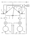
- Fig. 1 shows a schematic of a brake system for a two axle bogie railway car comprising an air supply 1 which, in use, supplies air to first and second channels 2, 3.
- Each channel 2,3 feeds to first and second brake actuators 10,11 and is provided with a respective inlet valve 4,6.
- Each inlet valve 4,6 is connected to a respective exhaust valve 5,7, which exhaust valve provides a vent to air.
- a further pneumatic connection 8 is provided between the channels 2 and 3, which pneumatic connection is provided with a link (further) valve 9 adapted to control the flow of air between the channels 2 and 3.
- Brake actuators 10,11 apply pressure in respective brake cylinders BC1,BC2, which apply the brakes on axles 12,13.
- the system is further provided with an electronic control unit 20 adapted to control the operation of the inlet valves 4,6, exhaust valves 5,7 and the link valve 9.
- Each of said aforementioned valves is provided with a counter, which counter records each operation of the valve.
- the electronic control unit (ECU) 20 is provided with further inputs from sensors on each axle adapted to detect low wheel to track adhesion (wheel slide). The ECU 20 also monitors the actual brake pressure in each brake cylinder.
- Each car of the railway vehicle is provided with its own ECU to provide a distributed control system.
- the instantaneous value of the counter is held in a volatile memory such as a RAM.
- the value of the counter is then stored in a non-volatile memory such as an EEPROM 21, which typically can store up to a million write operations.
- EEPROM 21 typically can store up to a million write operations.
- the valves will have a typical lifetime of up to 200 million operations, the data is downloaded at regular servicing intervals.
- the ECU 20 controls each pair of inlet and exhaust valves independently as separate control groups, comprising inlet valve 4 and exhaust valve 5 comprising inlet valve 6 and exhaust valve 7, respectively. In normal service braking operation, the ECU 20 selects one or other of the control groups or to increase or decrease the pressure in the brake actuators 10,11.
- the link valve 9 is open during normal operating conditions so that the pressure between the channels 2 and 3 is equalised.
- the choice of which one of the control groups is selected is determined by the electronic control unit 20.
- the selection can be made on several bases such as the total number of lifetime operations of the respective valves 4,5 and 6,7.
- Alternative bases include switching groups after a predetermined number of valve operations, after every single valve operation of group of valve operations. In practice an acceptable compromise is to switch the groups after every brake stop of the vehicle.
- the ECU 20 is adapted to close the link valve 9 to isolate the axle for which low adhesion has been determined.
- the ECU 20 can then operate the inlet and exhaust valves for the control group of that axle in accordance with its wheel slide protection programme to restore the desired adhesion to the rail.
- WSP generally involves a substantially increased number of valve operations in comparison to conventional servicing braking and the counters record this increased number of operations.
- the ECU 20 also monitors the actual brake pressure in each brake cylinder and compares the actual brake pressure with predetermined characteristic or target values. In the event that the difference between the actual brake pressure and the target value exceeds a predetermined value, the ECU 20 will operate both control groups in parallel to improve the response. This is particularly useful in the event that either one of the inlet or exhaust valves fails to open as the operation of the brakes on the bogie can then be controlled by the remaining control group via the other channel. In the event that such a fault is detected the ECU will also log the fault.
Landscapes
- Engineering & Computer Science (AREA)
- Mechanical Engineering (AREA)
- Transportation (AREA)
- Regulating Braking Force (AREA)
- Valves And Accessory Devices For Braking Systems (AREA)
- Braking Systems And Boosters (AREA)
- Control Of Throttle Valves Provided In The Intake System Or In The Exhaust System (AREA)
- Control Of Vehicle Engines Or Engines For Specific Uses (AREA)
Abstract
Description
- The invention relates to a brake system for use in a railway vehicle
- A typical railway vehicle comprises a number cars or trucks and several trainlines. The trainlines include both pneumatic and electrical lines connected in series which run along the length of the vehicle. One such pneumatic trainline is the main brake pipe. In a conventional arrangement the air pressure in the main brake pipe is used to bias the brake actuators on each bogie of a car in an off position, so that in the event of a pressure drop in the brake pipe due to a failure the brakes are applied.
- With normal service braking it is usual for the brake actuator pressure in all the actuators to be the same to ensure uniform braking. However, in some circumstances, such as where there is low wheel to rail adhesion, it is necessary to control the brake pressure on each axle individually to ensure uniform braking. This individual control, known as wheel slide protection (WSP), requires that the brake pressure at each axle be controllable independently of the brake pressure on other axles and/or bogies.
-
WO 01/62567 WO 01/62567 - The invention therefore seeks to a provide a brake system with a greater operational life
- According to the invention there is provided a brake system for use in a railway vehicle comprising an air supply adapted to supply, in use, air via first and second air channels to first and second brake actuators, the pressure of the air supplied to each actuator being controlled by a respective inlet and an exhaust valve, wherein a further valve is provided, which further valve is adapted to control, in use, airflow in an air channel between the respective inlet valves, actuation of the respective inlet, exhaust and the further valve being controlled by an electronic control unit, which electronic control unit has a counter for counting the number of valve operations performed by each respective inlet and exhaust valve, wherein the electronic control unit, in use, determines which of the respective inlet and exhaust valves are to be actuated to brake the railway vehicle, at least in part in dependence on the number of valve operations performed by the respective inlet and exhaust valves.
- In a preferred embodiment the electronic control unit determines of which of the inlet and exhaust valves are to be actuated so as to equalise wear on the valves. Preferably, the further valve is maintained in an open position to permit airflow from said first air channel to the second air channel and/or vice versa, such that application of pressure to the first and second brake actuators is controlled by only one of the respective inlet and exhaust valve pairs.
- Preferably, the further valve is closed so as to permit separate control of the respective pairs of inlet and exhaust valves. Preferably, the respective pairs of inlet and exhaust valves are controlled in parallel to increase air flow or to compensate for a failed valve. Preferably, the electronic control unit determines which respective inlet and exhaust valves are actuated based on the total number of valve operations of the inlet and exhaust valves. Preferably, the electronic control unit determines which respective inlet and exhaust valves are actuated, and alternates between respective pairs of inlet and exhaust valves after a predefined number of brake operations.
- In an alternative embodiment, the electronic control unit may determine which respective inlet and exhaust valves are actuated, and alternates between respective pairs of inlet and exhaust valves after a predetermined time interval.
- An exemplary embodiment of the invention will now be described in greater detail with reference to the drawings in which:
-
Fig. 1 shows a schematic of a brake system -
Fig. 1 shows a schematic of a brake system for a two axle bogie railway car comprising an air supply 1 which, in use, supplies air to first andsecond channels 2, 3. Eachchannel 2,3 feeds to first andsecond brake actuators respective inlet valve 4,6. Eachinlet valve 4,6 is connected to arespective exhaust valve pneumatic connection 8 is provided between thechannels 2 and 3, which pneumatic connection is provided with a link (further)valve 9 adapted to control the flow of air between thechannels 2 and 3.Brake actuators axles - The system is further provided with an
electronic control unit 20 adapted to control the operation of theinlet valves 4,6,exhaust valves link valve 9. Each of said aforementioned valves is provided with a counter, which counter records each operation of the valve. The electronic control unit (ECU) 20 is provided with further inputs from sensors on each axle adapted to detect low wheel to track adhesion (wheel slide). The ECU 20 also monitors the actual brake pressure in each brake cylinder. Each car of the railway vehicle is provided with its own ECU to provide a distributed control system. - In use, due to the high number of operations of the valves, the instantaneous value of the counter is held in a volatile memory such as a RAM. The value of the counter is then stored in a non-volatile memory such as an EEPROM 21, which typically can store up to a million write operations. As the valves will have a typical lifetime of up to 200 million operations, the data is downloaded at regular servicing intervals.
- The
ECU 20 controls each pair of inlet and exhaust valves independently as separate control groups, comprising inlet valve 4 andexhaust valve 5 comprisinginlet valve 6 andexhaust valve 7, respectively. In normal service braking operation, theECU 20 selects one or other of the control groups or to increase or decrease the pressure in thebrake actuators link valve 9 is open during normal operating conditions so that the pressure between thechannels 2 and 3 is equalised. - The choice of which one of the control groups is selected is determined by the
electronic control unit 20. The selection can be made on several bases such as the total number of lifetime operations of therespective valves - In the event that low wheel to rail adhesion is detected such as when the rotational speed of one axle differs by more than a predetermined amount from the adjacent axles, the
ECU 20 is adapted to close thelink valve 9 to isolate the axle for which low adhesion has been determined. The ECU 20 can then operate the inlet and exhaust valves for the control group of that axle in accordance with its wheel slide protection programme to restore the desired adhesion to the rail. WSP generally involves a substantially increased number of valve operations in comparison to conventional servicing braking and the counters record this increased number of operations. - The ECU 20 also monitors the actual brake pressure in each brake cylinder and compares the actual brake pressure with predetermined characteristic or target values. In the event that the difference between the actual brake pressure and the target value exceeds a predetermined value, the
ECU 20 will operate both control groups in parallel to improve the response. This is particularly useful in the event that either one of the inlet or exhaust valves fails to open as the operation of the brakes on the bogie can then be controlled by the remaining control group via the other channel. In the event that such a fault is detected the ECU will also log the fault.
Claims (8)
- A brake system for use in a railway vehicle comprising an air supply (1) adapted to supply, in use, air via first and second air channels (2,3) to first and second brake actuators (10,11), the pressure of the air supplied to each actuator being controlled by a respective inlet (4,6) and an exhaust (5,7) valve, wherein a further valve (9) is provided, which further valve (9) is adapted to control, in use, airflow in an air channel (2,3) between the respective inlet valves (4,6), actuation of the respective inlet (4,6), exhaust (5,7) and the further valve (9) being controlled by an electronic control unit (10), characterised in that electronic control unit (10) has a counter for counting the number of valve operations performed by each respective inlet (4,6) and exhaust (5,7) valve, wherein the electronic control unit (10), in use, determines which of the respective inlet (4,6) and exhaust (5,7) valves are to be actuated to brake the railway vehicle, at least in part in dependence on the number of valve operations performed by the respective inlet (4,6) and exhaust (5,7) valves.
- A brake system according to Claim 1, wherein in use, the electronic control unit (10) determines of which of the inlet (4,6) and exhaust (5,7) valves are to be actuated so as to equalise wear on the valves.
- A brake system according to Claim 1 or Claim 2, wherein, in use, the further valve (9) is maintained in an open position to permit airflow from said first air channel (2) to the second air channel (3) and/or vice versa, such that application of pressure to the first and second brake actuators (10,11) is controlled by only one of the respective inlet (4,6) and exhaust (5,7) valve pairs.
- A brake system according to any one of Claims 1 to 3, wherein, in use, the further valve (9) is closed so as to permit separate control of the respective pairs of inlet (4,6) and exhaust (5,7) valves.
- A brake system according to any one of Claims 1 to 4, wherein, in use, the respective pairs of inlet (4,6) and exhaust (5,7) valves are controlled in parallel to increase air flow or to compensate for a failed valve.
- A brake system according to any one of Claims 1 to 5, wherein the electronic control unit (10) determines which respective inlet (4,6) and exhaust (5,7) valves are actuated based on the total number of valve operations of the inlet and exhaust valves.
- A brake system according to any one of Claims 1 to 5, wherein the electronic control unit (10) determines which respective inlet (4,6) and exhaust (5,7) valves are actuated, and alternates between respective pairs of inlet (4,6) and exhaust (5,7) valves after a predefined number of brake operations.
- A brake system according to any one of Claims 1 to 5, wherein the electronic control unit (10) determines which respective inlet (4,6) and exhaust (5,7) valves are actuated, and alternates between respective pairs of inlet and exhaust valves after a predetermined time interval.
Applications Claiming Priority (2)
| Application Number | Priority Date | Filing Date | Title |
|---|---|---|---|
| GB0310704A GB2401413B (en) | 2003-05-09 | 2003-05-09 | Railway vehicle brake control system |
| PCT/GB2004/002011 WO2004098966A1 (en) | 2003-05-09 | 2004-05-10 | Railway vehicle brake control system |
Publications (2)
| Publication Number | Publication Date |
|---|---|
| EP1625059A1 EP1625059A1 (en) | 2006-02-15 |
| EP1625059B1 true EP1625059B1 (en) | 2011-07-27 |
Family
ID=9957766
Family Applications (1)
| Application Number | Title | Priority Date | Filing Date |
|---|---|---|---|
| EP04731949A Expired - Lifetime EP1625059B1 (en) | 2003-05-09 | 2004-05-10 | Brake system for use in a railway vehicle |
Country Status (9)
| Country | Link |
|---|---|
| US (1) | US8197013B2 (en) |
| EP (1) | EP1625059B1 (en) |
| JP (1) | JP2006525907A (en) |
| KR (1) | KR101041506B1 (en) |
| CN (1) | CN100381316C (en) |
| AT (1) | ATE517794T1 (en) |
| ES (1) | ES2368143T3 (en) |
| GB (1) | GB2401413B (en) |
| WO (1) | WO2004098966A1 (en) |
Families Citing this family (8)
| Publication number | Priority date | Publication date | Assignee | Title |
|---|---|---|---|---|
| JP2012251730A (en) * | 2011-06-03 | 2012-12-20 | Azbil Corp | Room pressure control system |
| DE102014107402B4 (en) * | 2014-05-26 | 2021-11-04 | Knorr-Bremse Systeme für Schienenfahrzeuge GmbH | Rail vehicle braking system with a conditioning device, conditioning device and method for operating a conditioning device |
| WO2016194185A1 (en) * | 2015-06-03 | 2016-12-08 | 三菱電機株式会社 | Refrigeration cycle device |
| ITUB20152565A1 (en) | 2015-07-28 | 2017-01-28 | Faiveley Transport Italia Spa | Pneumatic braking system for a railway vehicle. |
| CN106696986A (en) * | 2016-12-13 | 2017-05-24 | 中车株洲电力机车有限公司 | Rail train and braking control device thereof |
| US10315637B2 (en) * | 2017-03-20 | 2019-06-11 | Westinghouse Air Brake Technologies Corporation | Automatic brake backup control system and method |
| US11718281B2 (en) * | 2020-12-01 | 2023-08-08 | Faiveley Transport Rail Technologies India Private Limited | Brake control system |
| DE102022205826A1 (en) * | 2022-06-08 | 2023-12-14 | Robert Bosch Gesellschaft mit beschränkter Haftung | Method for operating a motor vehicle, device for operating a motor vehicle, motor vehicle |
Family Cites Families (17)
| Publication number | Priority date | Publication date | Assignee | Title |
|---|---|---|---|---|
| SU1031820A1 (en) * | 1982-03-10 | 1983-07-30 | Уральский электромеханический институт инженеров железнодорожного транспорта | Control apparatus for train brakes |
| JP2584429B2 (en) * | 1992-12-10 | 1997-02-26 | 株式会社ナブコ | Fluid pressure control device |
| JP2952798B2 (en) * | 1993-04-14 | 1999-09-27 | 本田技研工業株式会社 | Failure detection method in fluid pressure system and fluid pressure brake system for vehicle |
| JP2757802B2 (en) * | 1995-02-06 | 1998-05-25 | 株式会社デンソー | Vehicle traction control device |
| DE69713750T2 (en) * | 1996-04-17 | 2003-03-13 | Lucas Industries Ltd., Solihull | IMPROVEMENTS IN HYDRAULIC VEHICLE BRAKE SYSTEMS WITH ELECTRIC CONTROL |
| US5794739A (en) * | 1996-06-14 | 1998-08-18 | Westinghouse Air Brake Company | Pneumatic pressure operated parking brake for a railway vehicle brake system |
| US5813383A (en) * | 1996-09-04 | 1998-09-29 | Cummings; Henry W. | Variable displacement diesel engine |
| CA2214156C (en) * | 1996-09-13 | 2003-07-15 | New York Air Brake Corporation | Locomotive brake control unit with dynamic brake interlock |
| JPH10123019A (en) * | 1996-10-17 | 1998-05-15 | Denso Corp | Vehicle control device and replacement timing detection method using the same |
| JPH10148183A (en) * | 1996-11-20 | 1998-06-02 | Aisin Seiki Co Ltd | Fluid pressure source device |
| US5934765A (en) * | 1996-12-19 | 1999-08-10 | Westinghouse Air Brake Company | Electro-pneumatic brake system and controller therefor |
| JPH11245784A (en) * | 1998-03-03 | 1999-09-14 | Toyota Motor Corp | Hydraulic pressure control device |
| GB2359599A (en) * | 2000-02-25 | 2001-08-29 | Westinghouse Brake & Signal | Controlling the application of air pressure to brake actuators e.g.for railway vehicles |
| JP4264181B2 (en) * | 2000-03-30 | 2009-05-13 | 三菱重工業株式会社 | Control device and method for fluid actuator |
| DE10056565A1 (en) * | 2000-10-20 | 2002-08-29 | Continental Teves Ag & Co Ohg | Determining load or loading profile of motor vehicle control system e.g. ABS by counting active phases and/or duration of active phases of control system |
| US7997237B2 (en) * | 2008-09-10 | 2011-08-16 | Ford Global Technologies, Llc | Multi-stroke internal combustion engine |
| US7946259B2 (en) * | 2008-09-10 | 2011-05-24 | Ford Global Technologies, Llc | Multi-stroke internal combustion engine |
-
2003
- 2003-05-09 GB GB0310704A patent/GB2401413B/en not_active Expired - Lifetime
-
2004
- 2004-05-10 ES ES04731949T patent/ES2368143T3/en not_active Expired - Lifetime
- 2004-05-10 WO PCT/GB2004/002011 patent/WO2004098966A1/en not_active Ceased
- 2004-05-10 EP EP04731949A patent/EP1625059B1/en not_active Expired - Lifetime
- 2004-05-10 CN CNB2004800168736A patent/CN100381316C/en not_active Expired - Lifetime
- 2004-05-10 US US10/556,166 patent/US8197013B2/en active Active
- 2004-05-10 JP JP2006506236A patent/JP2006525907A/en active Pending
- 2004-05-10 AT AT04731949T patent/ATE517794T1/en not_active IP Right Cessation
- 2004-05-10 KR KR1020057021330A patent/KR101041506B1/en not_active Expired - Lifetime
Also Published As
| Publication number | Publication date |
|---|---|
| KR101041506B1 (en) | 2011-06-16 |
| GB0310704D0 (en) | 2003-06-11 |
| ATE517794T1 (en) | 2011-08-15 |
| GB2401413A (en) | 2004-11-10 |
| GB2401413B (en) | 2006-06-14 |
| ES2368143T3 (en) | 2011-11-14 |
| WO2004098966A1 (en) | 2004-11-18 |
| KR20060037248A (en) | 2006-05-03 |
| EP1625059A1 (en) | 2006-02-15 |
| US8197013B2 (en) | 2012-06-12 |
| US20070205657A1 (en) | 2007-09-06 |
| CN100381316C (en) | 2008-04-16 |
| CN1805872A (en) | 2006-07-19 |
| JP2006525907A (en) | 2006-11-16 |
Similar Documents
| Publication | Publication Date | Title |
|---|---|---|
| US6669308B1 (en) | Brake system for railway vehicles | |
| CN112867648B (en) | Redundant module of pneumatic braking system, pneumatic braking system and vehicle | |
| CN104428180B (en) | Control valve device for orbit vehicle arrester | |
| US11932219B2 (en) | Control device and method for controlling an actuator for actuating braking means of a vehicle, more particularly of a rail vehicle | |
| JPH07257360A (en) | Pneumatic / electro-pneumatic brake controller for railway vehicles | |
| US20220297652A1 (en) | Electrically controllable pneumatic brake system having a two-channel pressure modulator system | |
| CN108778873B (en) | Railway brake system for railway vehicles and method for braking railway vehicles with such a system | |
| US8197013B2 (en) | Railway vehicle brake control system | |
| JP7618533B2 (en) | Brake control system for rail vehicles | |
| CN119527259A (en) | Distributed controller design for optimized controller characteristics and increased valve service life | |
| US20030155808A1 (en) | Controlling pressure in brake actuation outputs | |
| US4564245A (en) | Parking brake control apparatus | |
| US20050275281A1 (en) | Modular braking system | |
| US7226135B2 (en) | Braking system for a self-powered rail vehicle provided with an anti-slip device | |
| JP2022531586A (en) | Rotation monitoring system for at least one axle for rail vehicles or trains | |
| US20220402471A1 (en) | Brake system for a utility vehicle, utility vehicle, and method for operating the brake system | |
| EP3183147B1 (en) | Valve arrangement | |
| JP2010513110A (en) | Braking devices used especially for trucks | |
| CN113508062A (en) | Railway vehicle brake system with parking brake indicator and railway vehicle equipped with such a system |
Legal Events
| Date | Code | Title | Description |
|---|---|---|---|
| PUAI | Public reference made under article 153(3) epc to a published international application that has entered the european phase |
Free format text: ORIGINAL CODE: 0009012 |
|
| 17P | Request for examination filed |
Effective date: 20051209 |
|
| AK | Designated contracting states |
Kind code of ref document: A1 Designated state(s): AT BE BG CH CY CZ DE DK EE ES FI FR GB GR HU IE IT LI LU MC NL PL PT RO SE SI SK TR |
|
| RIN1 | Information on inventor provided before grant (corrected) |
Inventor name: MIFLIN, RODNEY Inventor name: BRADLEY, ROSS Inventor name: TATE, DEREK |
|
| RAP1 | Party data changed (applicant data changed or rights of an application transferred) |
Owner name: KNORR-BREMSE RAIL SYSTEMS (UK) LIMITED |
|
| DAX | Request for extension of the european patent (deleted) | ||
| GRAP | Despatch of communication of intention to grant a patent |
Free format text: ORIGINAL CODE: EPIDOSNIGR1 |
|
| RTI1 | Title (correction) |
Free format text: BRAKE SYSTEM FOR USE IN A RAILWAY VEHICLE |
|
| GRAS | Grant fee paid |
Free format text: ORIGINAL CODE: EPIDOSNIGR3 |
|
| GRAA | (expected) grant |
Free format text: ORIGINAL CODE: 0009210 |
|
| AK | Designated contracting states |
Kind code of ref document: B1 Designated state(s): AT BE BG CH CY CZ DE DK EE ES FI FR GB GR HU IE IT LI LU MC NL PL PT RO SE SI SK TR |
|
| REG | Reference to a national code |
Ref country code: GB Ref legal event code: FG4D |
|
| REG | Reference to a national code |
Ref country code: CH Ref legal event code: EP |
|
| REG | Reference to a national code |
Ref country code: DE Ref legal event code: R096 Ref document number: 602004033648 Country of ref document: DE Effective date: 20110915 |
|
| REG | Reference to a national code |
Ref country code: NL Ref legal event code: T3 |
|
| REG | Reference to a national code |
Ref country code: SE Ref legal event code: TRGR |
|
| REG | Reference to a national code |
Ref country code: ES Ref legal event code: FG2A Ref document number: 2368143 Country of ref document: ES Kind code of ref document: T3 Effective date: 20111114 |
|
| REG | Reference to a national code |
Ref country code: AT Ref legal event code: MK05 Ref document number: 517794 Country of ref document: AT Kind code of ref document: T Effective date: 20110727 |
|
| PG25 | Lapsed in a contracting state [announced via postgrant information from national office to epo] |
Ref country code: PT Free format text: LAPSE BECAUSE OF FAILURE TO SUBMIT A TRANSLATION OF THE DESCRIPTION OR TO PAY THE FEE WITHIN THE PRESCRIBED TIME-LIMIT Effective date: 20111128 Ref country code: FI Free format text: LAPSE BECAUSE OF FAILURE TO SUBMIT A TRANSLATION OF THE DESCRIPTION OR TO PAY THE FEE WITHIN THE PRESCRIBED TIME-LIMIT Effective date: 20110727 Ref country code: BE Free format text: LAPSE BECAUSE OF FAILURE TO SUBMIT A TRANSLATION OF THE DESCRIPTION OR TO PAY THE FEE WITHIN THE PRESCRIBED TIME-LIMIT Effective date: 20110727 |
|
| PG25 | Lapsed in a contracting state [announced via postgrant information from national office to epo] |
Ref country code: CY Free format text: LAPSE BECAUSE OF FAILURE TO SUBMIT A TRANSLATION OF THE DESCRIPTION OR TO PAY THE FEE WITHIN THE PRESCRIBED TIME-LIMIT Effective date: 20110727 Ref country code: GR Free format text: LAPSE BECAUSE OF FAILURE TO SUBMIT A TRANSLATION OF THE DESCRIPTION OR TO PAY THE FEE WITHIN THE PRESCRIBED TIME-LIMIT Effective date: 20111028 Ref country code: AT Free format text: LAPSE BECAUSE OF FAILURE TO SUBMIT A TRANSLATION OF THE DESCRIPTION OR TO PAY THE FEE WITHIN THE PRESCRIBED TIME-LIMIT Effective date: 20110727 Ref country code: SI Free format text: LAPSE BECAUSE OF FAILURE TO SUBMIT A TRANSLATION OF THE DESCRIPTION OR TO PAY THE FEE WITHIN THE PRESCRIBED TIME-LIMIT Effective date: 20110727 Ref country code: PL Free format text: LAPSE BECAUSE OF FAILURE TO SUBMIT A TRANSLATION OF THE DESCRIPTION OR TO PAY THE FEE WITHIN THE PRESCRIBED TIME-LIMIT Effective date: 20110727 |
|
| PG25 | Lapsed in a contracting state [announced via postgrant information from national office to epo] |
Ref country code: SK Free format text: LAPSE BECAUSE OF FAILURE TO SUBMIT A TRANSLATION OF THE DESCRIPTION OR TO PAY THE FEE WITHIN THE PRESCRIBED TIME-LIMIT Effective date: 20110727 |
|
| PG25 | Lapsed in a contracting state [announced via postgrant information from national office to epo] |
Ref country code: RO Free format text: LAPSE BECAUSE OF FAILURE TO SUBMIT A TRANSLATION OF THE DESCRIPTION OR TO PAY THE FEE WITHIN THE PRESCRIBED TIME-LIMIT Effective date: 20110727 Ref country code: EE Free format text: LAPSE BECAUSE OF FAILURE TO SUBMIT A TRANSLATION OF THE DESCRIPTION OR TO PAY THE FEE WITHIN THE PRESCRIBED TIME-LIMIT Effective date: 20110727 |
|
| PLBE | No opposition filed within time limit |
Free format text: ORIGINAL CODE: 0009261 |
|
| STAA | Information on the status of an ep patent application or granted ep patent |
Free format text: STATUS: NO OPPOSITION FILED WITHIN TIME LIMIT |
|
| PG25 | Lapsed in a contracting state [announced via postgrant information from national office to epo] |
Ref country code: DK Free format text: LAPSE BECAUSE OF FAILURE TO SUBMIT A TRANSLATION OF THE DESCRIPTION OR TO PAY THE FEE WITHIN THE PRESCRIBED TIME-LIMIT Effective date: 20110727 |
|
| 26N | No opposition filed |
Effective date: 20120502 |
|
| REG | Reference to a national code |
Ref country code: DE Ref legal event code: R097 Ref document number: 602004033648 Country of ref document: DE Effective date: 20120502 |
|
| PG25 | Lapsed in a contracting state [announced via postgrant information from national office to epo] |
Ref country code: MC Free format text: LAPSE BECAUSE OF NON-PAYMENT OF DUE FEES Effective date: 20120531 |
|
| REG | Reference to a national code |
Ref country code: CH Ref legal event code: PL |
|
| PG25 | Lapsed in a contracting state [announced via postgrant information from national office to epo] |
Ref country code: LI Free format text: LAPSE BECAUSE OF NON-PAYMENT OF DUE FEES Effective date: 20120531 Ref country code: CH Free format text: LAPSE BECAUSE OF NON-PAYMENT OF DUE FEES Effective date: 20120531 |
|
| REG | Reference to a national code |
Ref country code: IE Ref legal event code: MM4A |
|
| PG25 | Lapsed in a contracting state [announced via postgrant information from national office to epo] |
Ref country code: IE Free format text: LAPSE BECAUSE OF NON-PAYMENT OF DUE FEES Effective date: 20120510 |
|
| PG25 | Lapsed in a contracting state [announced via postgrant information from national office to epo] |
Ref country code: BG Free format text: LAPSE BECAUSE OF FAILURE TO SUBMIT A TRANSLATION OF THE DESCRIPTION OR TO PAY THE FEE WITHIN THE PRESCRIBED TIME-LIMIT Effective date: 20111027 |
|
| PG25 | Lapsed in a contracting state [announced via postgrant information from national office to epo] |
Ref country code: TR Free format text: LAPSE BECAUSE OF FAILURE TO SUBMIT A TRANSLATION OF THE DESCRIPTION OR TO PAY THE FEE WITHIN THE PRESCRIBED TIME-LIMIT Effective date: 20110727 |
|
| PG25 | Lapsed in a contracting state [announced via postgrant information from national office to epo] |
Ref country code: LU Free format text: LAPSE BECAUSE OF NON-PAYMENT OF DUE FEES Effective date: 20120510 |
|
| PG25 | Lapsed in a contracting state [announced via postgrant information from national office to epo] |
Ref country code: HU Free format text: LAPSE BECAUSE OF FAILURE TO SUBMIT A TRANSLATION OF THE DESCRIPTION OR TO PAY THE FEE WITHIN THE PRESCRIBED TIME-LIMIT Effective date: 20040510 |
|
| REG | Reference to a national code |
Ref country code: FR Ref legal event code: PLFP Year of fee payment: 12 |
|
| REG | Reference to a national code |
Ref country code: FR Ref legal event code: PLFP Year of fee payment: 13 |
|
| REG | Reference to a national code |
Ref country code: FR Ref legal event code: PLFP Year of fee payment: 14 |
|
| REG | Reference to a national code |
Ref country code: FR Ref legal event code: PLFP Year of fee payment: 15 |
|
| REG | Reference to a national code |
Ref country code: DE Ref legal event code: R082 Ref document number: 602004033648 Country of ref document: DE Representative=s name: JENSENS IP LIMITED, IE |
|
| P01 | Opt-out of the competence of the unified patent court (upc) registered |
Effective date: 20230530 |
|
| PGFP | Annual fee paid to national office [announced via postgrant information from national office to epo] |
Ref country code: NL Payment date: 20230526 Year of fee payment: 20 Ref country code: IT Payment date: 20230526 Year of fee payment: 20 Ref country code: FR Payment date: 20230525 Year of fee payment: 20 Ref country code: ES Payment date: 20230601 Year of fee payment: 20 Ref country code: DE Payment date: 20230515 Year of fee payment: 20 Ref country code: CZ Payment date: 20230425 Year of fee payment: 20 |
|
| PGFP | Annual fee paid to national office [announced via postgrant information from national office to epo] |
Ref country code: SE Payment date: 20230525 Year of fee payment: 20 |
|
| PGFP | Annual fee paid to national office [announced via postgrant information from national office to epo] |
Ref country code: GB Payment date: 20230428 Year of fee payment: 20 |
|
| REG | Reference to a national code |
Ref country code: DE Ref legal event code: R071 Ref document number: 602004033648 Country of ref document: DE |
|
| REG | Reference to a national code |
Ref country code: NL Ref legal event code: MK Effective date: 20240509 |
|
| REG | Reference to a national code |
Ref country code: ES Ref legal event code: FD2A Effective date: 20240524 |
|
| REG | Reference to a national code |
Ref country code: GB Ref legal event code: PE20 Expiry date: 20240509 |
|
| REG | Reference to a national code |
Ref country code: SE Ref legal event code: EUG |
|
| PG25 | Lapsed in a contracting state [announced via postgrant information from national office to epo] |
Ref country code: GB Free format text: LAPSE BECAUSE OF EXPIRATION OF PROTECTION Effective date: 20240509 |
|
| PG25 | Lapsed in a contracting state [announced via postgrant information from national office to epo] |
Ref country code: ES Free format text: LAPSE BECAUSE OF EXPIRATION OF PROTECTION Effective date: 20240511 |
|
| PG25 | Lapsed in a contracting state [announced via postgrant information from national office to epo] |
Ref country code: CZ Free format text: LAPSE BECAUSE OF EXPIRATION OF PROTECTION Effective date: 20240510 |
|
| PG25 | Lapsed in a contracting state [announced via postgrant information from national office to epo] |
Ref country code: GB Free format text: LAPSE BECAUSE OF EXPIRATION OF PROTECTION Effective date: 20240509 Ref country code: ES Free format text: LAPSE BECAUSE OF EXPIRATION OF PROTECTION Effective date: 20240511 Ref country code: CZ Free format text: LAPSE BECAUSE OF EXPIRATION OF PROTECTION Effective date: 20240510 |