EP1624956B1 - Bone cement mixing cartridge with a releasably locked drive piston, the drive piston configured to be unlocked by a delivery device. - Google Patents
Bone cement mixing cartridge with a releasably locked drive piston, the drive piston configured to be unlocked by a delivery device. Download PDFInfo
- Publication number
- EP1624956B1 EP1624956B1 EP20040751914 EP04751914A EP1624956B1 EP 1624956 B1 EP1624956 B1 EP 1624956B1 EP 20040751914 EP20040751914 EP 20040751914 EP 04751914 A EP04751914 A EP 04751914A EP 1624956 B1 EP1624956 B1 EP 1624956B1
- Authority
- EP
- European Patent Office
- Prior art keywords
- piston
- bone cement
- cartridge
- mixing
- set forth
- Prior art date
- Legal status (The legal status is an assumption and is not a legal conclusion. Google has not performed a legal analysis and makes no representation as to the accuracy of the status listed.)
- Expired - Lifetime
Links
- 238000002156 mixing Methods 0.000 title claims description 178
- 239000002639 bone cement Substances 0.000 title claims description 88
- 230000007246 mechanism Effects 0.000 claims description 49
- 239000000843 powder Substances 0.000 claims description 25
- 239000007788 liquid Substances 0.000 claims description 20
- 238000007599 discharging Methods 0.000 claims description 5
- 239000000203 mixture Substances 0.000 claims description 4
- 230000008901 benefit Effects 0.000 description 11
- 230000001154 acute effect Effects 0.000 description 8
- 238000000034 method Methods 0.000 description 8
- 210000005069 ears Anatomy 0.000 description 6
- 230000013011 mating Effects 0.000 description 6
- 238000000576 coating method Methods 0.000 description 5
- 239000011248 coating agent Substances 0.000 description 4
- 230000008878 coupling Effects 0.000 description 4
- 238000010168 coupling process Methods 0.000 description 4
- 238000005859 coupling reaction Methods 0.000 description 4
- 238000005260 corrosion Methods 0.000 description 3
- 230000007797 corrosion Effects 0.000 description 3
- 239000004033 plastic Substances 0.000 description 3
- 230000009471 action Effects 0.000 description 2
- 238000011882 arthroplasty Methods 0.000 description 2
- 239000004568 cement Substances 0.000 description 2
- 210000001624 hip Anatomy 0.000 description 2
- 239000000178 monomer Substances 0.000 description 2
- 210000002445 nipple Anatomy 0.000 description 2
- 229920001343 polytetrafluoroethylene Polymers 0.000 description 2
- 239000004810 polytetrafluoroethylene Substances 0.000 description 2
- 230000001954 sterilising effect Effects 0.000 description 2
- 238000004659 sterilization and disinfection Methods 0.000 description 2
- 230000002411 adverse Effects 0.000 description 1
- 210000000988 bone and bone Anatomy 0.000 description 1
- 230000000295 complement effect Effects 0.000 description 1
- 229920001577 copolymer Polymers 0.000 description 1
- 230000001419 dependent effect Effects 0.000 description 1
- 230000000994 depressogenic effect Effects 0.000 description 1
- 210000004394 hip joint Anatomy 0.000 description 1
- 238000002347 injection Methods 0.000 description 1
- 239000007924 injection Substances 0.000 description 1
- 210000002414 leg Anatomy 0.000 description 1
- 238000012986 modification Methods 0.000 description 1
- 230000004048 modification Effects 0.000 description 1
- 229910052759 nickel Inorganic materials 0.000 description 1
- PXHVJJICTQNCMI-UHFFFAOYSA-N nickel Substances [Ni] PXHVJJICTQNCMI-UHFFFAOYSA-N 0.000 description 1
- 230000000399 orthopedic effect Effects 0.000 description 1
- -1 polytetrafluoroethylene Polymers 0.000 description 1
- 238000007790 scraping Methods 0.000 description 1
- 238000007789 sealing Methods 0.000 description 1
- 239000000243 solution Substances 0.000 description 1
- 238000001356 surgical procedure Methods 0.000 description 1
- 230000007704 transition Effects 0.000 description 1
- 210000000689 upper leg Anatomy 0.000 description 1
- 238000009736 wetting Methods 0.000 description 1
- 238000004804 winding Methods 0.000 description 1
- 210000000707 wrist Anatomy 0.000 description 1
Images


Classifications
-
- A—HUMAN NECESSITIES
- A61—MEDICAL OR VETERINARY SCIENCE; HYGIENE
- A61B—DIAGNOSIS; SURGERY; IDENTIFICATION
- A61B17/00—Surgical instruments, devices or methods, e.g. tourniquets
- A61B17/56—Surgical instruments or methods for treatment of bones or joints; Devices specially adapted therefor
- A61B17/58—Surgical instruments or methods for treatment of bones or joints; Devices specially adapted therefor for osteosynthesis, e.g. bone plates, screws, setting implements or the like
- A61B17/88—Osteosynthesis instruments; Methods or means for implanting or extracting internal or external fixation devices
- A61B17/8802—Equipment for handling bone cement or other fluid fillers
- A61B17/8805—Equipment for handling bone cement or other fluid fillers for introducing fluid filler into bone or extracting it
- A61B17/8822—Equipment for handling bone cement or other fluid fillers for introducing fluid filler into bone or extracting it characterised by means facilitating expulsion of fluid from the introducer, e.g. a screw pump plunger, hydraulic force transmissions, application of vibrations or a vacuum
-
- A—HUMAN NECESSITIES
- A61—MEDICAL OR VETERINARY SCIENCE; HYGIENE
- A61B—DIAGNOSIS; SURGERY; IDENTIFICATION
- A61B17/00—Surgical instruments, devices or methods, e.g. tourniquets
- A61B17/56—Surgical instruments or methods for treatment of bones or joints; Devices specially adapted therefor
- A61B17/58—Surgical instruments or methods for treatment of bones or joints; Devices specially adapted therefor for osteosynthesis, e.g. bone plates, screws, setting implements or the like
- A61B17/88—Osteosynthesis instruments; Methods or means for implanting or extracting internal or external fixation devices
- A61B17/8802—Equipment for handling bone cement or other fluid fillers
- A61B17/8805—Equipment for handling bone cement or other fluid fillers for introducing fluid filler into bone or extracting it
- A61B17/8827—Equipment for handling bone cement or other fluid fillers for introducing fluid filler into bone or extracting it with filtering, degassing, venting or pressure relief means
-
- B—PERFORMING OPERATIONS; TRANSPORTING
- B01—PHYSICAL OR CHEMICAL PROCESSES OR APPARATUS IN GENERAL
- B01F—MIXING, e.g. DISSOLVING, EMULSIFYING OR DISPERSING
- B01F31/00—Mixers with shaking, oscillating, or vibrating mechanisms
- B01F31/40—Mixers with shaking, oscillating, or vibrating mechanisms with an axially oscillating rotary stirrer
-
- B—PERFORMING OPERATIONS; TRANSPORTING
- B01—PHYSICAL OR CHEMICAL PROCESSES OR APPARATUS IN GENERAL
- B01F—MIXING, e.g. DISSOLVING, EMULSIFYING OR DISPERSING
- B01F33/00—Other mixers; Mixing plants; Combinations of mixers
- B01F33/50—Movable or transportable mixing devices or plants
- B01F33/501—Movable mixing devices, i.e. readily shifted or displaced from one place to another, e.g. portable during use
- B01F33/5011—Movable mixing devices, i.e. readily shifted or displaced from one place to another, e.g. portable during use portable during use, e.g. hand-held
- B01F33/50114—Movable mixing devices, i.e. readily shifted or displaced from one place to another, e.g. portable during use portable during use, e.g. hand-held of the hand-held gun type
-
- B—PERFORMING OPERATIONS; TRANSPORTING
- B01—PHYSICAL OR CHEMICAL PROCESSES OR APPARATUS IN GENERAL
- B01F—MIXING, e.g. DISSOLVING, EMULSIFYING OR DISPERSING
- B01F33/00—Other mixers; Mixing plants; Combinations of mixers
- B01F33/70—Mixers specially adapted for working at sub- or super-atmospheric pressure, e.g. combined with de-foaming
-
- B—PERFORMING OPERATIONS; TRANSPORTING
- B01—PHYSICAL OR CHEMICAL PROCESSES OR APPARATUS IN GENERAL
- B01F—MIXING, e.g. DISSOLVING, EMULSIFYING OR DISPERSING
- B01F35/00—Accessories for mixers; Auxiliary operations or auxiliary devices; Parts or details of general application
- B01F35/56—General build-up of the mixers
- B01F35/562—General build-up of the mixers the mixer or mixing elements being collapsible, i.e. when discharging the products
-
- B—PERFORMING OPERATIONS; TRANSPORTING
- B01—PHYSICAL OR CHEMICAL PROCESSES OR APPARATUS IN GENERAL
- B01F—MIXING, e.g. DISSOLVING, EMULSIFYING OR DISPERSING
- B01F35/00—Accessories for mixers; Auxiliary operations or auxiliary devices; Parts or details of general application
- B01F35/75—Discharge mechanisms
- B01F35/754—Discharge mechanisms characterised by the means for discharging the components from the mixer
- B01F35/75425—Discharge mechanisms characterised by the means for discharging the components from the mixer using pistons or plungers
- B01F35/754251—Discharge mechanisms characterised by the means for discharging the components from the mixer using pistons or plungers reciprocating in the mixing receptacle
-
- A—HUMAN NECESSITIES
- A61—MEDICAL OR VETERINARY SCIENCE; HYGIENE
- A61B—DIAGNOSIS; SURGERY; IDENTIFICATION
- A61B17/00—Surgical instruments, devices or methods, e.g. tourniquets
- A61B17/56—Surgical instruments or methods for treatment of bones or joints; Devices specially adapted therefor
- A61B17/58—Surgical instruments or methods for treatment of bones or joints; Devices specially adapted therefor for osteosynthesis, e.g. bone plates, screws, setting implements or the like
- A61B17/88—Osteosynthesis instruments; Methods or means for implanting or extracting internal or external fixation devices
- A61B17/8802—Equipment for handling bone cement or other fluid fillers
- A61B17/8833—Osteosynthesis tools specially adapted for handling bone cement or fluid fillers; Means for supplying bone cement or fluid fillers to introducing tools, e.g. cartridge handling means
- A61B2017/8838—Osteosynthesis tools specially adapted for handling bone cement or fluid fillers; Means for supplying bone cement or fluid fillers to introducing tools, e.g. cartridge handling means for mixing bone cement or fluid fillers
-
- A—HUMAN NECESSITIES
- A61—MEDICAL OR VETERINARY SCIENCE; HYGIENE
- A61F—FILTERS IMPLANTABLE INTO BLOOD VESSELS; PROSTHESES; DEVICES PROVIDING PATENCY TO, OR PREVENTING COLLAPSING OF, TUBULAR STRUCTURES OF THE BODY, e.g. STENTS; ORTHOPAEDIC, NURSING OR CONTRACEPTIVE DEVICES; FOMENTATION; TREATMENT OR PROTECTION OF EYES OR EARS; BANDAGES, DRESSINGS OR ABSORBENT PADS; FIRST-AID KITS
- A61F2/00—Filters implantable into blood vessels; Prostheses, i.e. artificial substitutes or replacements for parts of the body; Appliances for connecting them with the body; Devices providing patency to, or preventing collapsing of, tubular structures of the body, e.g. stents
- A61F2/02—Prostheses implantable into the body
- A61F2/30—Joints
- A61F2002/30001—Additional features of subject-matter classified in A61F2/28, A61F2/30 and subgroups thereof
- A61F2002/30108—Shapes
- A61F2002/30199—Three-dimensional shapes
- A61F2002/30224—Three-dimensional shapes cylindrical
- A61F2002/30235—Three-dimensional shapes cylindrical tubular, e.g. sleeves
-
- A—HUMAN NECESSITIES
- A61—MEDICAL OR VETERINARY SCIENCE; HYGIENE
- A61F—FILTERS IMPLANTABLE INTO BLOOD VESSELS; PROSTHESES; DEVICES PROVIDING PATENCY TO, OR PREVENTING COLLAPSING OF, TUBULAR STRUCTURES OF THE BODY, e.g. STENTS; ORTHOPAEDIC, NURSING OR CONTRACEPTIVE DEVICES; FOMENTATION; TREATMENT OR PROTECTION OF EYES OR EARS; BANDAGES, DRESSINGS OR ABSORBENT PADS; FIRST-AID KITS
- A61F2/00—Filters implantable into blood vessels; Prostheses, i.e. artificial substitutes or replacements for parts of the body; Appliances for connecting them with the body; Devices providing patency to, or preventing collapsing of, tubular structures of the body, e.g. stents
- A61F2/02—Prostheses implantable into the body
- A61F2/30—Joints
- A61F2002/30001—Additional features of subject-matter classified in A61F2/28, A61F2/30 and subgroups thereof
- A61F2002/30316—The prosthesis having different structural features at different locations within the same prosthesis; Connections between prosthetic parts; Special structural features of bone or joint prostheses not otherwise provided for
- A61F2002/30329—Connections or couplings between prosthetic parts, e.g. between modular parts; Connecting elements
- A61F2002/30476—Connections or couplings between prosthetic parts, e.g. between modular parts; Connecting elements locked by an additional locking mechanism
- A61F2002/30505—Connections or couplings between prosthetic parts, e.g. between modular parts; Connecting elements locked by an additional locking mechanism spring biased
-
- A—HUMAN NECESSITIES
- A61—MEDICAL OR VETERINARY SCIENCE; HYGIENE
- A61F—FILTERS IMPLANTABLE INTO BLOOD VESSELS; PROSTHESES; DEVICES PROVIDING PATENCY TO, OR PREVENTING COLLAPSING OF, TUBULAR STRUCTURES OF THE BODY, e.g. STENTS; ORTHOPAEDIC, NURSING OR CONTRACEPTIVE DEVICES; FOMENTATION; TREATMENT OR PROTECTION OF EYES OR EARS; BANDAGES, DRESSINGS OR ABSORBENT PADS; FIRST-AID KITS
- A61F2/00—Filters implantable into blood vessels; Prostheses, i.e. artificial substitutes or replacements for parts of the body; Appliances for connecting them with the body; Devices providing patency to, or preventing collapsing of, tubular structures of the body, e.g. stents
- A61F2/02—Prostheses implantable into the body
- A61F2/30—Joints
- A61F2002/30001—Additional features of subject-matter classified in A61F2/28, A61F2/30 and subgroups thereof
- A61F2002/30316—The prosthesis having different structural features at different locations within the same prosthesis; Connections between prosthetic parts; Special structural features of bone or joint prostheses not otherwise provided for
- A61F2002/30329—Connections or couplings between prosthetic parts, e.g. between modular parts; Connecting elements
- A61F2002/30518—Connections or couplings between prosthetic parts, e.g. between modular parts; Connecting elements with possibility of relative movement between the prosthetic parts
- A61F2002/3052—Connections or couplings between prosthetic parts, e.g. between modular parts; Connecting elements with possibility of relative movement between the prosthetic parts unrestrained in only one direction, e.g. moving unidirectionally
- A61F2002/30522—Connections or couplings between prosthetic parts, e.g. between modular parts; Connecting elements with possibility of relative movement between the prosthetic parts unrestrained in only one direction, e.g. moving unidirectionally releasable, e.g. using a releasable ratchet
-
- A—HUMAN NECESSITIES
- A61—MEDICAL OR VETERINARY SCIENCE; HYGIENE
- A61F—FILTERS IMPLANTABLE INTO BLOOD VESSELS; PROSTHESES; DEVICES PROVIDING PATENCY TO, OR PREVENTING COLLAPSING OF, TUBULAR STRUCTURES OF THE BODY, e.g. STENTS; ORTHOPAEDIC, NURSING OR CONTRACEPTIVE DEVICES; FOMENTATION; TREATMENT OR PROTECTION OF EYES OR EARS; BANDAGES, DRESSINGS OR ABSORBENT PADS; FIRST-AID KITS
- A61F2/00—Filters implantable into blood vessels; Prostheses, i.e. artificial substitutes or replacements for parts of the body; Appliances for connecting them with the body; Devices providing patency to, or preventing collapsing of, tubular structures of the body, e.g. stents
- A61F2/02—Prostheses implantable into the body
- A61F2/30—Joints
- A61F2002/30001—Additional features of subject-matter classified in A61F2/28, A61F2/30 and subgroups thereof
- A61F2002/30316—The prosthesis having different structural features at different locations within the same prosthesis; Connections between prosthetic parts; Special structural features of bone or joint prostheses not otherwise provided for
- A61F2002/30535—Special structural features of bone or joint prostheses not otherwise provided for
- A61F2002/30601—Special structural features of bone or joint prostheses not otherwise provided for telescopic
-
- A—HUMAN NECESSITIES
- A61—MEDICAL OR VETERINARY SCIENCE; HYGIENE
- A61F—FILTERS IMPLANTABLE INTO BLOOD VESSELS; PROSTHESES; DEVICES PROVIDING PATENCY TO, OR PREVENTING COLLAPSING OF, TUBULAR STRUCTURES OF THE BODY, e.g. STENTS; ORTHOPAEDIC, NURSING OR CONTRACEPTIVE DEVICES; FOMENTATION; TREATMENT OR PROTECTION OF EYES OR EARS; BANDAGES, DRESSINGS OR ABSORBENT PADS; FIRST-AID KITS
- A61F2/00—Filters implantable into blood vessels; Prostheses, i.e. artificial substitutes or replacements for parts of the body; Appliances for connecting them with the body; Devices providing patency to, or preventing collapsing of, tubular structures of the body, e.g. stents
- A61F2/02—Prostheses implantable into the body
- A61F2/30—Joints
- A61F2/46—Special tools or methods for implanting or extracting artificial joints, accessories, bone grafts or substitutes, or particular adaptations therefor
- A61F2002/4685—Special tools or methods for implanting or extracting artificial joints, accessories, bone grafts or substitutes, or particular adaptations therefor by means of vacuum
-
- A—HUMAN NECESSITIES
- A61—MEDICAL OR VETERINARY SCIENCE; HYGIENE
- A61F—FILTERS IMPLANTABLE INTO BLOOD VESSELS; PROSTHESES; DEVICES PROVIDING PATENCY TO, OR PREVENTING COLLAPSING OF, TUBULAR STRUCTURES OF THE BODY, e.g. STENTS; ORTHOPAEDIC, NURSING OR CONTRACEPTIVE DEVICES; FOMENTATION; TREATMENT OR PROTECTION OF EYES OR EARS; BANDAGES, DRESSINGS OR ABSORBENT PADS; FIRST-AID KITS
- A61F2220/00—Fixations or connections for prostheses classified in groups A61F2/00 - A61F2/26 or A61F2/82 or A61F9/00 or A61F11/00 or subgroups thereof
- A61F2220/0025—Connections or couplings between prosthetic parts, e.g. between modular parts; Connecting elements
-
- A—HUMAN NECESSITIES
- A61—MEDICAL OR VETERINARY SCIENCE; HYGIENE
- A61F—FILTERS IMPLANTABLE INTO BLOOD VESSELS; PROSTHESES; DEVICES PROVIDING PATENCY TO, OR PREVENTING COLLAPSING OF, TUBULAR STRUCTURES OF THE BODY, e.g. STENTS; ORTHOPAEDIC, NURSING OR CONTRACEPTIVE DEVICES; FOMENTATION; TREATMENT OR PROTECTION OF EYES OR EARS; BANDAGES, DRESSINGS OR ABSORBENT PADS; FIRST-AID KITS
- A61F2230/00—Geometry of prostheses classified in groups A61F2/00 - A61F2/26 or A61F2/82 or A61F9/00 or A61F11/00 or subgroups thereof
- A61F2230/0063—Three-dimensional shapes
- A61F2230/0069—Three-dimensional shapes cylindrical
-
- B—PERFORMING OPERATIONS; TRANSPORTING
- B01—PHYSICAL OR CHEMICAL PROCESSES OR APPARATUS IN GENERAL
- B01F—MIXING, e.g. DISSOLVING, EMULSIFYING OR DISPERSING
- B01F2101/00—Mixing characterised by the nature of the mixed materials or by the application field
- B01F2101/20—Mixing of ingredients for bone cement
Definitions
- the present invention generally relates to a bone cement mixing and delivery system. More specifically, the present invention relates to a mixing cartridge for receiving liquid and powder components of bone cement to be mixed, a mixing device for mixing the components, and a delivery gun for discharging the bone cement from the mixing cartridge into an anatomical site of a patient.
- Bone cement mixing and delivery systems are well known for mixing liquid and powder components of bone cement and delivering the prepared bone cement to an anatomical site during various surgical procedures.
- Bone cement is particularly useful in orthopedic procedures in which a prosthetic device is fixed to a bone or joint structure to improve the strength, rigidity, and movement of the structure.
- THA total hip arthroplasty
- bone cement is used to fix the prosthetic device in place in a medullary canal of a femur.
- the bone cement is prepared in a mixing cartridge.
- the mixing cartridge includes a cylinder having proximal and distal ends with a mixing chamber defined between the ends.
- the mixing cartridge further includes a cap covering the proximal end of the cylinder and a piston disposed in the distal end of the cylinder such that the mixing chamber is further defined between the cap and the piston.
- the piston may be releasably secured in a locked position in the cylinder by a cotter pin.
- the cap supports a mixing device, i.e., a mixing shaft and blade, for mixing the liquid and powder components of the bone cement in the mixing chamber.
- the mixing cartridge is prepared for inserting into a delivery gun to discharge the bone cement. This may include disengaging the mixing shaft and coupling a nozzle to the cap to provide a discharge point for the bone cement.
- the piston is released from the locked position in the distal end of the cylinder by pulling the cotter pin. This allows the piston to be driven by the delivery gun through the mixing chamber to discharge the bone cement from the nozzle.
- An alternative solution for securing and releasing the piston is shown in United States Patent No. 5,328,262 to Lidgren et aL
- the piston is releasably secured in the locked position in the distal end of the cylinder by a gripping portion in the form of a flange, which extends along only a portion of an inner periphery of the cylinder.
- the piston in Lidgren et al. has a corresponding gripping portion in the form of an outwardly directed lip that protrudes behind the flange.
- the lip defines a groove with an outer surface of the piston to receive the flange.
- the flange is rotated through the groove until the flange has been rotated past the lip.
- a typical delivery gun includes a ram disk that engages the piston and drives the piston through the mixing chamber to discharge the bone cement from the nozzle.
- the delivery gun includes a cradle for supporting the mixing cartridge and a casing for supporting a drive rod that engages the ram disk and advances the ram disk to drive the piston.
- the drive rod includes a plurality of teeth and a pawl member engages the teeth to advance the drive rod.
- a trigger supports the pawl member and the casing rotatably supports the trigger. Actuation of the trigger relative to the casing urges the pawl member against the teeth to advance the drive rod.
- EP 1 005 900 A2 discloses a mixing cartridge according to the preamble of present claim 1.
- US 6,406,175 B1 discloses a device for preparing and injecting a polymeric bone cement under sterile, isobaric and isovolumic conditions.
- the device includes a cylindrical vessel holding a volume of polymeric powder and a disk agitator mounted on a shaft passing through an aperture in a proximal end wall of the vessel and extending beyond the agitator through a delivery port in an opposite wall of the vessel.
- a piston can be selectively coupled to the disk in order to inject the contents of the vessel through the outlet port.
- the cement is ejected by braking off a distal, tubular section of the shaft and mounting the broken off section over an external bushing surrounding the outlet port and moving the piston toward the outlet port to expel the contents of the vessel.
- a mixing cartridge according to claim 1 adapted for use with a delivery device for discharging bone cement from the mixing cartridge is provided.
- the dependent claims relate to advantageous configurations of the mixing cartridge and the use of the mixing cartridge in a bone cement system.
- a mixing cartridge for receiving liquid and powder components of bone cement to be mixed for medical use comprises a cylinder having proximal and distal ends with a mixing chamber defined therebetween.
- the cylinder includes a cylinder wall extending between the ends about a longitudinal axis of the cylinder.
- a piston is disposed in the cylinder at the distal end such that the mixing chamber is further defined between the proximal end and the piston.
- a locking member is coupled to the piston to lock the piston in the distal end.
- the locking member includes a male portion engaging a female portion in the cylinder wall to place the piston in a locked position at the distal end of the cylinder.
- the locking member includes a resilient portion for biasing the male portion into mating engagement with the female portion. The piston remains in the locked position at the distal end of the cylinder while mixing the liquid and powder components.
- One advantage of the mixing cartridge is the conveniently positioned locking member used to lock the piston in the distal end.
- a delivery gun is also disclosed for discharging the bone cement from the cartridge once the bone cement is prepared.
- the delivery gun comprises a casing for supporting the cartridge.
- a drive mechanism is supported by the casing and advanceable relative to the casing to force the bone cement from the cartridge.
- the casing pivotally supports a trigger operatively connected to the drive mechanism to advance the drive mechanism upon actuation of the trigger to force the bone cement from the cartridge.
- a linkage system works in conjunction with the trigger to advance the drive mechanism.
- the linkage system comprises a first link pivotally connected to the casing and a second link interconnecting the first link and the trigger such that actuating the trigger moves the second link and the first link to advance the drive mechanism.
- An advantage of the delivery gun is the use of the linkage system to increase the mechanical advantage needed to successfully advance the drive mechanism and force the bone cement from the cartridge while minimizing fatigue to a user of the delivery gun.
- the drive mechanism includes a drive rod and gripper plates to advance the drive rod.
- the gripper plates frictionally engage the drive rod to advance the drive rod when the trigger is actuated.
- the gripper plates include mating pegs and notches to align adjacent gripper plates.
- the gripper plates are coated to increase lubricity and corrosion resistance thereof.
- the drive mechanism includes a drive rod and first and second pawl members to advance the drive rod.
- the second pawl member is movable into engagement with teeth on the drive rod for high-speed advancement of the drive rod and out from engagement with the teeth for low-speed advancement.
- the first pawl member engages the teeth to advance the drive rod.
- both pawl members engage the teeth, but only the second pawl member works to advance the drive rod.
- a bone cement mixing and delivery system is also disclosed.
- the mixing and delivery system includes the cartridge and the delivery gun.
- the locking member includes a release button to release the piston from the locked position.
- the delivery gun includes a release mechanism integrated into the drive mechanism to engage the release button.
- a bone cement loading system for receiving the liquid and powder components of the bone cement is also disclosed.
- the loading system includes the cylinder with the piston locked in the distal end.
- a base defining a cavity is provided for receiving and securing the distal end of the cylinder.
- a funnel is provided for coupling to the proximal end of the cylinder to channel the powder component of the bone cement into the mixing chamber.
- the funnel has a proximal end with an oblong oval-shaped periphery to facilitate loading of the powder component of the bone cement into the mixing chamber and a distal end with a circular periphery for snugly fitting into the proximal end of the cylinder.
- One particular advantage to this loading system is the use of the oblong oval-shaped funnel. The shape of the funnel reduces any mess typically associated with filling the mixing chamber with powder.
- a bone cement mixing system comprising the mixing cartridge and a mixing shaft and blade is also disclosed.
- the blade is coupled to the mixing shaft and disposed in the mixing chamber for rotating with the mixing shaft about the longitudinal axis to mix the liquid and powder components of the bone cement.
- the blade includes a center hub coupled to the mixing shaft and an outer ring extending from the center hub. The outer ring forms an acute angle with the longitudinal axis of between twenty and seventy degrees to ensure adequate mixing of the bone cement in the mixing chamber.
- a method of mixing the liquid and powder components of the bone cement in the mixing chamber includes using a rotary power tool connected to a portion of the mixing shaft extending outside of the mixing chamber to mix the liquid and powder components of the bone cement.
- the blade is disposed in the mixing chamber while being operatively connected to the portion of the mixing shaft extending outside of the mixing chamber.
- the rotary power tool is first connected to the portion of the mixing shaft extending outside of the mixing chamber. Then the rotary power tool is actuated to rotate the blade and mix the liquid and powder components of the bone cement. At the same time, the rotary power tool is axially displaced relative to the mixing cartridge to completely mix the liquid and powder components of the bone cement.
- Figure 1 is an exploded perspective view of a mixing cartridge of the present invention in combination with a mixing shaft and blade;
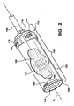
- Figure 2 is an assembled perspective view of the mixing cartridge with the mixing shaft and blade supported therein;
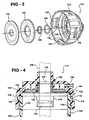
- Figure 3 is an exploded perspective view of a cap of the mixing cartridge
- Figure 4 is a cross-sectional view of the cap of Figure 3 and a partial cross-sectional view of a cylinder of the mixing cartridge to illustrate fitting of the cap to the cylinder;
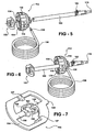
- Figure 5 is an exploded perspective view of the cap and the mixing shaft and blade
- Figure 6 is an assembled perspective view of the cap with the mixing shaft and blade supported therein;
- Figure 7 is a perspective view of the blade
- Figure 7A is a side elevational view of the blade of Fig. 7 ;
- FIGS 8-8A and 9 are perspective views of alternative blades
- Figure 10 is a an exploded perspective view of the mixing shaft and a latch rod
- Figure 11 is an elevational end view of the mixing shaft and latch rod of Fig. 10 ;
- Figure 12 is a cross-sectional view of the mixing shaft and latch rod of Figs. 10 and 11 ;
- Figure 13 is an exploded perspective view of a release latch coupling the mixing shaft and latch rod;
- Figures 14A-14C illustrate the release of the blade from the mixing shaft
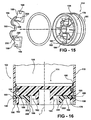
- Figure 15 is an exploded perspective view of a piston of the mixing cartridge
- Figure 16 is a cross-sectional view of the piston of Fig. 15 ;
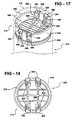
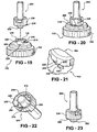
- Figure 17 is a perspective view of an alternative piston of the mixing cartridge
- Figure 18 is a top view of the alternative piston of Fig. 17 ;
- Figure 19 is an exploded perspective view of the cap and a nozzle
- Figure 20 is an assembled perspective view of the cap and nozzle
- Figure 21 is a blown-up view of a locking mechanism of the cap and nozzle
- Figures 22-23 are perspective views of the nozzle
- Figure 24 is a perspective view of a delivery gun illustrating a linkage system of the delivery gun
- FIGS. 24A-24B illustrate alternative linkage systems
- Figure 25 is an elevational view illustrating release of a locking member securing the piston
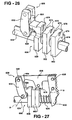
- Figure 26 is a partial perspective view of an alternative linkage system and drive mechanism of the delivery gun
- Figure 27 is a partial perspective view of the alternative linkage system and drive mechanism of Fig. 26 employing a striker to prevent freeze-up of the drive mechanism;
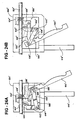
- Figures 28 is an elevational view of a second alternative linkage system and drive mechanism of the delivery gun in a low-speed position
- Figure 29 is a perspective view of the second alternative linkage system and drive mechanism in the low-speed position
- Figure 30 is an elevational view of the second alternative linkage system and drive mechanism in a high-speed position
- Figure 31 is a perspective view of the second alternative linkage system and drive mechanism in the high-speed position
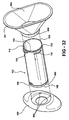
- Figure 32 is an exploded view of a cylinder of the mixing cartridge and a base and funnel used to fill the cylinder with components of bone cement;
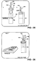
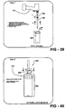
- FIGS 33-42 illustrate various steps associated with the present disclosure.
- the bone cement mixing and delivery system comprises a mixing cartridge 100 for receiving liquid monomer and powdered copolymer components of bone cement to be mixed, a mixing device (mixing shaft 150 and blade 152 ) for mixing the components, and a delivery device, e.g., a delivery gun 500, for discharging the bone cement from the mixing cartridge 100 into an anatomical site (not shown).
- a delivery device e.g., a delivery gun 500
- An exemplary use for the bone cement is to secure a prosthetic device used to replace a joint structure such as in a total hip arthroplasty (THA) procedure.
- THA total hip arthroplasty
- the bone cement mixing system comprises the mixing cartridge 100 in combination with the mixing shaft 150 and blade 152 used to mix the components of the bone cement in the mixing cartridge 100.
- the mixing cartridge 100 includes a cylinder 102 having proximal 104 and distal 106 ends.
- a mixing chamber 108 is defined between the ends 104, 106.
- the cylinder 102 includes a cylinder wall 110 extending between the ends 104, 106, about a longitudinal axis L.
- a cap 112 is coupled to the cylinder 102 at the proximal end 104 and a piston 114 is disposed in the cylinder 102 at the distal end 106 such that the mixing chamber 108 is further defined between the cap 112 and the piston 114.
- the components of the bone cement are placed in the mixing chamber 108 and mixed by the mixing shaft 150 and blade 152, as will be described further below.
- the cylinder 102 has locking strips 116 disposed on the cylinder wall 110 at the proximal end 104 to insert into locking slots 118 on the cap 112.
- Each of the locking strips 116 include a straight portion lying perpendicular relative to the longitudinal axis L and an angled portion lying at an angle relative to the straight portion.
- the locking strips 116 and locking slots 118 could be reversed, i.e., the locking strips 116 positioned on the cap 112 and the locking slots 118 defined in the cylinder wall 110.
- the locking strips 116 and locking slots 118 are configured to provide quick locking of the cap 112 onto the cylinder 102 with a one-quarter turn of the cap 112.
- a groove 120 is formed in the cylinder 102 at the proximal end 104 to seat an o-ring seal 122.
- the o-ring seal 122 assists in sealing the cap 112 to the cylinder 102.
- the cap 112 includes radially inwardly protruding ramps 124 that lead into the locking slots 118 to facilitate the fit with the locking strips 116 on the cylinder wall 110.
- the locking strips 116 are positioned between the ramps 124.
- the ramps 124 cam the locking strips 116 proximally to urge the proximal end 104 of the cylinder 102 into a sealed relationship with the cap 112, as shown in FIG. 4 (only a portion of the cylinder wall 110 with two locking strips 116 is shown in FIG. 4 for illustrative purposes).
- an o-ring seal 126 and dynamic seal 128 operate together within an orifice 130 in the cap 112 to movably support and seal to the mixing shaft 150.
- the mixing shaft 150 slides through the orifice 130 and the dynamic seal 128 and is movably supported therein.
- the dynamic seal 128 allows nearly frictionless rotational, as well as axial movement of the mixing shaft 150 within the mixing chamber 108 to mix the liquid and powder components of the bone cement, while maintaining a snug fit within the orifice 130.
- a filter 132 and liner 134 are positioned on an interior of the cap 112 to allow a vacuum to be drawn in the mixing chamber 108 by way of a vacuum port 136.
- the vacuum port 136 is isolated from the mixing chamber 108 by the filter 132 and liner 134 to prevent fouling of a vacuum pump (not shown). Referring to FIGS. 5-6 , a vacuum tube 138 is shown attached to the vacuum port 136 to draw the vacuum in the mixing chamber 108 during mixing.
- the blade 152 used to mix the bone cement is shown.
- the blade 152 is integrally formed from plastic in one piece and has an outer ring 154 connected to a center hub 156 by vanes 158. Ears 160 protrude radially inwardly from the center hub 156 to facilitate a releasable connection to the mixing shaft 150.
- the releasable connection is described further below.
- the outer ring 154 forms an acute angle ⁇ with the longitudinal axis L of the cylinder 102 (which is also a rotational mixing axis of the blade 152).
- the acute angle ⁇ is important for efficient mixing of the bone cement
- the acute angle ⁇ is preferably between twenty and seventy degrees, and more preferably sixty degrees.
- the blade 152 has an effective height H that is greater than one quarter inch to ensure adequate mixing. Preferably, the effective height H of the blade 152 is approximately one half inch.
- two radially inwardly protruding fingers 157 are attached to the outer ring 154.
- One of the fingers 157 protrudes radially inwardly in a first plane and the other finger 157 protrudes radially inwardly in a second plane spaced from and parallel to the first plane.
- the center hub 156 is positioned between the planes.
- the fingers 157 are used to scrape proximal and distal regions of the mixing chamber 108 to ensure complete mixing.
- a protruding node 159 is also attached to the outer ring 154. The node 159 protrudes radially outwardly to control spacing between the blade 152 and an inner periphery of the cylinder wall 110 by scraping along the inner periphery of the cylinder wall 110 in the mixing chamber 108.
- FIGS. 8 and 8A illustrate alternative blades 252, 352 that could also be used to mix the bone cement.
- Each of the blades 152, 252, 352 is designed to flatten at the proximal end 104 of the cylinder 102 adjacent to the cap 112 after the blade 152, 252, 352 is released from the mixing shaft 150 in the mixing chamber 108. This ensures that the maximum possible amount of bone cement can be discharged from the mixing cartridge 100.
- the blade 152 is flexible and the outer wall 154 flattens into a plane perpendicular to the longitudinal axis L and occupied by the center hub 156, as illustrated by hidden lines in FIG. 7A .
- each of the center hubs 156, 256, 356 are sized to partially fit within the aperture 130 defined in the cap 112.
- FIG. 9 Another alternative blade 452 is shown in FIG. 9 .
- This blade 452 is a relatively thick disk 452 with chamfered ends 453 forming an acute chamfer angle with a sidewall 457.
- the chamfer angle is preferably sixty degrees.
- the disk is about one half inch thick and about one eighth inch less in diameter than the inner periphery of the cylinder wall 110.
- the inner periphery of the cylinder wall 110 is about two and one quarter inches in diameter.
- the slight distance between the side wall 457 of the disk 452 and the inner periphery of the cylinder wall 110 creates a shear force on the bone cement as the disk 452 is rotated and moved axially in the mixing chamber 108.
- the shear force is the force applied to the bone cement to mix the bone cement.
- This blade 452 also includes a space 455 formed in a center of the disk 452 and ears 460 for releasably attaching to the mixing shaft 150.
- the mixing shaft 150 has a release latch 162 for releasing the blade 152 from the mixing shaft 150 once mixing of the bone cement is complete.
- the release latch 162 moves between a holding position and a releasing position. In the holding position, the blade 152 is secured to the mixing shaft 150 to mix the bone cement in the mixing chamber 108. In the releasing position, the blade 152 is released from the mixing shaft 150 to remain in the mixing chamber 108 while the mixing shaft 150 is removed from the cap 112 to make way for a nozzle 204, as will be described further below.
- the release latch 162 is operatively connected to a latch rod 164, which latches the blade 152 to the mixing shaft 150 in the holding position.
- the latch rod 164 defines a split cavity 166 for receiving split legs 168 of the release latch 162 in a snap-fit manner.
- the latch rod 164 is rotatably supported within the mixing shaft 150.
- the transition of the release latch 162 between the holding position and the releasing position is illustrated.
- the exposed end 170 of the latch rod 164 is generally "T" shaped
- the corresponding end 172 of the mixing shaft 150 has opposed notches 174 that are adapted to receive the ears 160 on the center hub 156 of the blade 152. Initially, the ears 160 are positioned in the notches 174 and the exposed end 170 is positioned over the ears 160 to hold the blade 152 to the mixing shaft 150. See FIG. 14A . To release the blade 152, the release latch 162 is depressed and rotated.
- Rotating the release latch 162 rotates the latch rod 164 with respect to the mixing shaft 150 thus rotating the exposed end 170 away from the ears 160 to release the blade 152. See FIG. 14B . With the blade 152 released, the mixing shaft 150 is withdrawn from the cap 112 while the blade 152 remains in the mixing chamber 108.
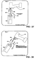
- a proximal end 176 of the mixing shaft 150 which represents a portion of the mixing shaft 150 extending outside of the mixing chamber 108 during mixing, is adapted to engage a rotary power tool 177 (see FIG. 37 ), such as a reamer drill, used to rotate the mixing shaft 150 and blade 152 and mix the bone cement.
- the proximal end 176 of the mixing shaft 150 is operatively connected to the blade 152 to transfer the rotation of the rotary power tool 177 to the blade 152.
- the operative connection is removed.
- the operative connection is also removed if the portion of the mixing shaft 150 extending outside of the mixing chamber 108 is severed from the rest of the mixing shaft 150 in the mixing chamber 108, as in alternative embodiments.
- a manually operated mixing handle could engage the mixing shaft 150 at the proximal end 176 to mix the bone cement in other embodiments.
- the piston 114 is positioned within the distal end 106 of the cylinder 102 to further seal the mixing chamber 108.
- the piston 114 has a skirt 178 extending about the inner periphery of the cylinder wall 110.
- the piston 114 also includes a proximal end 180 and a distal end 182 defining a cavity 184.
- the piston 114 is releasably secured in a locked position in the distal end 106 of the cylinder 102 by a locking member 186.
- the locking member 186 is disposed in the cavity 184 and includes diametrically opposed locking tabs 188 protruding into diametrically opposed slots 190 defined in the cylinder wall 110 to secure the piston 114 to the cylinder 102.
- the slots 190 could be in the form of any suitable female portion, e.g., slot, groove, channel, etc., used for interlocking with a corresponding male portion such as the locking tabs 188.
- the locking member 186 could also be used for one-way locking, i.e., for preventing only proximal movement of the piston 114.
- the locking member 186 is integrally formed from plastic and a resilient portion 192 of the locking member 186 biases the locking tabs 188 radially outwardly from the longitudinal axis L into the slots 190.
- the resilient portion 192 is in the form of a thin resilient ribbon 192 acting like a spring and extending is a winding shape between the locking tabs 188.
- the locking tabs 188 couple the locking member 186 to the piston 114 by protruding through carrier slots 194 formed in the skirt 178.
- a step 196 protrudes into each of the carrier slots 194 to define a guide for sliding engagement within a channel 198 partially defined in each of the locking tabs 188.
- the carrier slots 194 are axially and radially aligned with the slots 190 formed in the cylinder wall 110.
- the piston 114 is locked at the distal end 106 of the cylinder 102 while the liquid and powder components are added and mixed in the mixing cartridge 100.
- the piston 114 is released from the locked position after mixing of the bone cement is complete.
- Release buttons 200 integrally formed with the locking tabs 188, are used to release the piston 114 from the locked position.
- the release buttons 200 are disposed on the locking tabs 188 and protrude distally therefrom.
- Each of the release buttons 200 includes a cam surface 202 forming an acute angle with the longitudinal axis L.
- the piston 114 is released from the locked position by squeezing the release buttons 200 radially inwardly against the bias of the resilient portion 192 to withdraw the locking tabs 188 from the slots 190. This action can be performed either manually or mechanically, as will be described further below. After release from the slots 190, the locking tabs 188 remain coupled to the piston 114 in the carrier slots 194.
- the alternative locking member 386 includes locking tabs 388 that are biased radially outwardly from the longitudinal axis L of the cylinder 302 to engage the slots 390 in the cylinder wall 310.
- four slots 390 are defined in the cylinder wall 310 to receive the locking tabs 388.
- the resilient portion 392 is further defined as a resilient base 392 resiliently supporting each of the locking tabs 388 on the piston 314 with each of the locking tabs 388 being radially biased outwardly from the skirt 378 of the piston 314 to engage the slots 390 in the cylinder wall 310.
- the release buttons 400 are further defined as fingers 400 extending radially inwardly toward the longitudinal axis L of the cylinder 302 with the fingers 400 being engageable to urge the locking tabs 388 radially inwardly and withdraw the locking tabs 388 from the slots 390 in the cylinder wall 310 to release the piston 314 from the locked position.
- the nozzle 204 is positioned on the cap 112.
- the nozzle 204 is set in place by pushing a hollow shaft 205 of the nozzle 204 down into the orifice 130 of the cap 112 and then twisting the nozzle 204 slightly, about one-quarter turn.
- the nozzle 204 is attached to the cap 112 to prepare the mixing cartridge 100 for placement into the delivery gun 500.
- the cap 112 has a nipple 206 protruding from an outer surface 208 thereof.
- the nipple 206 has tabs 210, which engage detent members 212 in the nozzle 204. After the nozzle 204 is fully rotated into position, the tabs 210 fully engage the detent members 212 while being positioned proximal to the detent members 212 to secure the nozzle 204 in place.
- a stop 214 on the cap 112, best shown in FIG. 19 prevents the nozzle 204 from rotating freely in the clockwise direction after the tabs 210 have engaged the detent members 212.
- the stop 214 extends downwardly from one of the tabs 210 to abut a side surface 216 of one of the detent members 212 to prevent further clockwise rotation.
- the nozzle 204 and cap 112 have first 218 and second 220 locking protrusions.
- the first locking protrusion 218 acts as a detent and slides over the second locking protrusion 220 to a locked position as illustrated in FIG. 21 .
- rear flat surfaces 222, 224 of the locking protrusions 218, 220 abut one another to prevent the nozzle 204 from being turned in the opposite direction, thereby preventing removal of the nozzle 204 from the cap 112.
- the nozzle 204 can be removed by deflecting an outer skirt 226 of the nozzle 204 and rotating the nozzle 204 counterclockwise thereby disengaging the locking protrusions 218, 220.
- Both the nozzle 204 and cap 112 are formed from plastic, which facilitates the detent-like locking and unlocking of the nozzle 204 to the cap 112.
- the delivery gun 500 of the present invention includes a cradle 502 for supporting the mixing cartridge 100 and a casing 504 fixed to the cradle 502 for supporting a drive mechanism 506, a linkage system 508, and corresponding components.
- the cradle 502 includes an endplate 510, which has an opening 512 for receipt of the nozzle 204.
- the endplate 510 holds the mixing cartridge 100 in position in the cradle 502.
- the casing 504 and the endplate 510 are connected by two connecting bars 514 (one on each side of the mixing cartridge 100) to reduce the weight of the delivery gun 500.
- a handle 516 is integrally formed with the casing 504 to maneuver the delivery gun 500 during use.
- the piston 114 To dispense the bone cement from the mixing cartridge 100, the piston 114 must first be released from the locked position. Referring to FIG. 25 , this is accomplished using a release mechanism 518 integrated into the delivery gun 500.
- a ram disk 520 protrudes into the cavity 184 in the distal end 182 of the piston 114.
- the release mechanism 518 is integrated into the ram disk 520.
- the release mechanism 518 includes a bearing surface 522 forming an acute angle with the longitudinal axis L for catching the release buttons 200 to cam the release buttons 200 radially inwardly. More specifically, the cam surfaces 202 of the release buttons 200 slide along the bearing surface 522, while being cammed radially inwardly.
- This action pulls the locking tabs 188 radially inwardly to withdraw the locking tabs 188 from the slots 190 in the cylinder wall 110 and release the piston 114 from the locked position (when the alternative piston 314 is used, the ram disk has a flat bearing surface that axially presses the fingers 400 proximally to bend each resilient base 392 inwardly and urge the locking tabs 388 radially inward).
- a centering pin 800 can be used to center the ram disk 520 in a centering cavity 802 of the piston 114 to facilitate the release of the piston 114 from the locked position.
- the drive mechanism 506 includes a drive rod 524 movably supported by bushings 526 in the casing 504.
- the ram disk 520 is fixed to the drive rod 524.
- the drive mechanism 506 further includes a first gripper plate 528 responsive to movement of the linkage system 508 upon actuation of a trigger 530.
- the first gripper plate 528 defines an aperture surrounding the drive rod 524. The first gripper plate 528 frictionally engages the drive rod 524 to advance the drive rod 524.
- the first gripper plate 528 is urged forward while in frictional contact with the drive rod 524 by the linkage system 508 when the trigger 530 is actuated.
- the first gripper plate 528 thereby advances the drive rod 524 and ram disk 520 relative to the casing 504 to drive the piston 114 and force the bone cement from the mixing cartridge 100.
- the trigger 530 is pivotally supported by the casing 504 and operatively connected to the drive mechanism 506 to advance the drive mechanism 506 upon actuation of the trigger 530.
- the linkage system 508 includes a first link 532, which is pivotally mounted to the casing 504 about a pivot axis A adjacent to the first gripper plate 528.
- the first link 532 is adapted to engage the first gripper plate 528 when the first link 532 pivots about the pivot axis A.
- a second link 536 pivotally interconnects the trigger 530 to the first link 532 via support pins 538, 540.
- the links 532, 536 and trigger 530 are interconnected to move in unison upon rotation of the trigger 530 about a second pivot axis B.
- the second link 536 rotates the first link 532 about the pivot axis A, which engages the first gripper plate 528 and urges the first gripper plate 528 forward while the first gripper plate 528 is in frictional engagement with the drive rod 524 thereby advancing the drive rod 524.
- a return spring 542 returns the links 532, 536 and the trigger 530 to an initial position upon release of the trigger 530.
- a first spring 534 momentarily disengages the first gripper plate 528 from the drive rod 524 to slide the first gripper plate 528 back to an initial position to await the next pull of the trigger 530.
- the casing 504 pivotally supports the first link 532 and the trigger 530 about the pivot axes A and B via support pins 544, 546.
- a speed-changing link 548 is pivotally connected to the second link 536 about a support pin 549.
- the speed-changing link 548 selectively pivots into and out from engagement with the first gripper plate 528 by way of a switch 550.
- the speed-changing link 548 pivots between a high-speed position and a low-speed position about the support pin 549 (the low-speed position is shown in FIG. 24 ).
- the high-speed position corresponds to faster advancement of the drive rod 524 at a lower force. This allows the user to quickly advance the drive rod 524 to drive the piston 114 and dispense high volumes of bone cement at low pressure.
- the low-speed position corresponds to slower advancement of the drive rod 524 at a higher force, which exerts more force on the piston 114 to pressurize the bone cement
- the first gripper plate 528 and the speed-changing link 548 have complementary first and second coupling devices 552, 554 used to couple the first gripper plate 528 with the speed-changing link 548 in the high-speed position. More specifically, in the embodiment of FIG. 24 , the first gripper plate 528 has a shoulder 552 that is received within a channel 554 on the speed-changing link 548. The speed-changing link 548 engages the shoulder 552 in the high-speed position. In the high-speed position, a user's gripping force is transmitted through the trigger 530 to the second link 536 and the speed-changing link 548 to engage the first gripper plate 528 and advance the drive rod 524. The speed-changing link 548 is isolated from the first gripper plate 528 in the low-speed position.
- the low-speed position corresponds to the speed-changing link 548 being switched or disconnected from the shoulder 552.
- the user's gripping force is transmitted through the trigger 530 to both the first 532 and second 536 links to engage the first gripper plate 528 and advance the drive rod 524.
- the user can better pressurize the bone cement during injection.
- the pivot axes A and B and the links 532, 536, 548 are positioned above the drive rod 524, while the trigger 530 extends below the drive rod 524.
- a channel 556 defined in the trigger 530 facilitates this configuration.
- Moving the second pivot axis B away from a user's hand results in better usage of the stronger index and ring fingers by allowing those fingers more travel distance as the trigger 530 is actuated.
- This configuration also allows the handle 516 to be closer to the drive rod 524, which is believed to reduce wrist strain when the user pushes the delivery gun 500 forward during cement pressurization. Another benefit is that it allows for a more streamlined casing design and better weight distribution.
- a secondary gripper plate 562 is mounted about the drive rod 524 adjacent to the first gripper plate 528.
- the addition of one or more secondary gripper plates 562 to the first gripper plate 528 adds strength to the delivery gun 500 while still permitting proper operation.
- By using two or more gripper plates 528, 562, increased frictional contact with the drive rod 524 is obtained without adversely affecting performance.
- a release pin 558 disengages the gripper plates 528, 562 to allow a user to freely move the drive rod 524 by hand.
- the release pin 558 is connected to a retainer plate 560 and is adapted to engage the first gripper plate 528.
- the retainer plate 560 When the retainer plate 560 is pushed by the user, the release pin 558 engages the first gripper plate 528 which forces the first gripper plate 528 to tilt back against the bias of the first spring 534 thus releasing the drive rod 524. Any secondary gripper plates 562 follow.
- pushing the retainer plate 560 also pivots the retainer plate 560 releasing its engagement with the drive rod 524. With both the retainer plate 560 and the gripper plates 528, 562 released, the drive rod 524 is free to move. This allows the user to manually move the drive rod 524 with respect to the casing 504.
- the delivery gun 500 is unique among bone cement guns with a friction-plate mechanism in the way that it handles wear and deformation of the gripper plates 528, 562.
- the gripper plates 528, 562 are tilted by the first spring 534 into frictional contact with the drive rod 524. Regardless of the amount of wear or deformation of the gripper plates 528, 562 or the drive rod 524, the gripper plates 528, 562 require no further tilting to engage the drive rod 524 upon actuation of the trigger 530. Thus, advancement of the drive rod 524 is produced over the entire actuation of the trigger 530 and efficiency is maintained throughout the life of the delivery gun 500.
- FIGS. 24A and 24B alternatives of the linkage system 508' and 508" are shown. These alternatives are represented with similar numerals to the embodiment of FIG. 24 to indicate like parts.
- FIG. 24A illustrates a configuration of the linkage system 508' in which the linkage system 508' lies beneath the drive rod 524'.
- the speed-changing link 548' in this embodiment is pivotally connected to the first gripper plate 528' and includes a hook-shaped end to engage the support pin 538' in the high-speed position and disengage the support pin 538' in the low-speed position.
- FIG. 24A illustrate
- FIGS. 24B illustrates a configuration of the linkage system 508" in which the first gripper plate 528" is pushed by the linkage system 508", as opposed to being pulled by the linkage system 508 and 508' in FIGS. 24 and 24A .
- the speed-changing link 548" is pivotally connected to the first gripper plate 528" to pivot into engagement with a notch 555" defined in the trigger 530" in the high-speed position and out from engagement with the notch 555" in the low-speed position.
- These alternatives of the linkage system 508' and 508 " illustrate the flexibility of design, e.g., the selection of mechanical advantage, provided by the linkage system.
- the linkage system 608 comprises the same components as previously described with an improved first link 632 and gripper plates 628, 662.
- a plurality of secondary gripper plates 662 are aligned along the drive rod 624 next to the first gripper plate 628.
- the first link 632 defines a female recess 664 and the first gripper plate 628 includes a male member 668 for mating engagement with the female recess 664.
- the secondary gripper plates 662 are aligned relative to the first gripper plate 628 via mating notches 670 and pegs 672 formed therein.
- the notches 670 and pegs 672 assume the same shape to mate with one another and maintain alignment. This arrangement minimizes alignment changes that may cause slipping or uneven wear.
- the arrangement also reduces contact between the gripper plates 628, 662 and an interior wall of the casing 504.
- the gripper plates 628, 662 are shown spaced in FIG. 26 for illustration only. In practice, the gripper plates 628, 662 abut one another, as shown in FIG. 27 .
- each of the gripper plates 628, 662 also defines a pair of semi-spherical grooves 674.
- FIG. 26 only the first of the pair of grooves 674 are shown in each of the gripper plates 628, 662.
- the other of the pair of grooves 674 is located in a rear surface of each of the gripper plates 628, 662, cater-cornered from the first of the pair of grooves 674.
- These grooves 674 increase the frictional contact with the drive rod 624.
- the gripper plates 628, 662 are urged forward while in frictional engagement with the drive rod 624 by the first link 632, a substantial portion of a rim 676 defined by each of the grooves 674 frictionally contacts the drive rod 624.
- FIG. 27 shows a way to prevent this condition.
- a striker 678 in the form of a downwardly protruding portion of the second link 636, closely follows one of the gripper plates 628, 662 during actuation of the trigger 630.
- the striker 678 will contact the notch 670 in the closest gripper plate 628, 662 and dislodge the gripper plate 628, 662 from the drive rod 624.
- the first spring 634 can then properly return the gripper plates 628, 662 to their initial positions.
- a coating has been added to an exterior of each of the gripper plates 528, 562, 628, 662 in FIGS. 24 and 26-27 .
- the coating increases lubricity and corrosion resistance. This facilitates sliding between the gripper plates 528, 562, 628, 662 as they engage the drive rod 524, 624.
- the coating also reduces corrosion due to autoclave sterilization that may cause the gripper plates 528, 562, 628, 662 to adhere to one another and prevent proper engagement with the drive rod 524, 624.
- the coating used may be Electroless-Nickel with polytetrafluoroethylene (PTFE) or other like coatings possessing the same or similar properties.
- FIGS. 28-31 alternatives of the drive mechanism 706 and linkage system 708 are shown.
- This configuration also provides selective high-speed and low-speed advancement of the drive rod 724.
- This alternative drive mechanism 706 eliminates the gripper plate by providing teeth 780 on the drive rod 724.
- a cross-section of the drive rod 724 shows the teeth 780 on a flat upper surface 782, while a lower surface 784 is smooth and round.
- the first link 732 which in previous embodiments urged the first gripper plate 528, 628 forward with the drive rod 524, 624, now pivotally supports a first pawl member 786.
- the first pawl member 786 is spring-biased into engagement with the teeth 780.
- a second pawl member 788 is pivotally supported by the second link 736.
- the second pawl member 788 is pivotable between a high-speed position in which the second pawl member 788 is spring-biased into engagement with the teeth 780 to advance the drive rod 724, and a low-speed position in which the second pawl member 788 is disengaged and isolated from the teeth 780.
- the first pawl member 786 advances the drive rod 724.
- the low-speed position is illustrated in FIGS. 28-29 .
- the first pawl member 786 remains in engagement with the teeth 780, but only ratchets along the teeth 780 as the second pawl member 788 advances the drive rod 724.
- the high-speed position is illustrated in FIGS. 30-31 .. The principle of increasing mechanical advantage in the low-speed position relative to the high-speed position also applies in this embodiment.
- the switch 750 is used to pivot the second pawl member 788 out from engagement with the teeth 780 of the drive rod 724 in the low-speed position (see FIGS. 28-29 ) and into engagement with the teeth 780 in the high-speed position (see FIGS. 30-31 ).
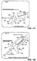
- the switch 750 extends through the casing 704 and terminates in a button that is manipulated by a user to move the second pawl member 788 between the high-speed and low-speed positions (see briefly FIGS. 41-42 ). This also applies to the switch 550 used to move the speed-changing link 548 in previous embodiments.
- a spring-biased non-return pawl member 790 retains the drive rod 724 in position upon advancement.
- the drive rod 724 can be freely moved in the casing 704 by rotating the drive rod 724 one hundred and eighty degrees such that the pawl members 786, 788, 790 are out of engagement with the teeth 780.
- the pawl members 786, 788, 790 ride on the smooth lower surface 784 of the drive rod 724 allowing the user to freely pull the drive rod 724 relative to the casing 704. This is generally disclosed in the '654 patent to Nic.
- Each of the pawl members 786, 788, 790 are pivotally supported by pins.
- Springs such as those shown in the ⁇ 654 patent to Nic, bias the pawl members into engagement with the teeth 780 on the drive rod 724 (except when the switch 750 acts against the bias of the spring in the low-speed position to disengage the second pawl member 788 from the teeth 780).
- the bone cement loading system comprises a base 900 supporting the cylinder 102 while loading the liquid and powder components of the bone cement into the mixing chamber 108.
- the base includes a cavity for receiving the distal end 106 of the cylinder 102.
- Detents 903 are formed in the cavity.
- a groove 905 is defined in an outer surface of the cylinder 102 to receive the detents 903 and facilitate a snug fit between the base 900 and the cylinder 102. It should be appreciated that the detents 903 could be formed on the cylinder 102 with the groove 905 defined in the base 900.
- the distal end 106 of the cylinder 102 may also be press fit into the base 900.
- the base 900 is oblong and oval in shape to fully support the cylinder 102 on a work surface, while the cavity is circular in shape to fit the circular shaped cylinder 102.
- a funnel 902 couples to the cylinder 102 to channel the powder into the cylinder 102 during loading.
- the funnel 902 includes a proximal end 911 having an oblong oval-shaped periphery to facilitate the loading of the powder into the mixing chamber 108 and a distal end 909 having a circular periphery to snugly fit inside the proximal end 104 of the cylinder 102.
- FIGS 33-42 illustrate ten steps for preparing and injecting the bone cement.
- the mixing cartridge 100, delivery gun 500, and other components are generically shown in each step for illustrative purposes only.
- the funnel 902 is coupled to the cylinder 102 and the powder is poured into the mixing chamber 108.
- the vacuum line 138 is attached to the vacuum port 136 and a vacuum is drawn in the mixing chamber 108 with the liquid and powder components therein.
- the mixing shaft 150 is moved axially with respect to the mixing cartridge 100 and rotated by the power tool.
- the blade 152 (not shown in FIG. 38 ) is moved axially the entire extent of the mixing cartridge 100 while rotating to ensure that the liquid and powder components are fully mixed.
Landscapes
- Health & Medical Sciences (AREA)
- Chemical Kinetics & Catalysis (AREA)
- Chemical & Material Sciences (AREA)
- Orthopedic Medicine & Surgery (AREA)
- Surgery (AREA)
- Life Sciences & Earth Sciences (AREA)
- Medical Informatics (AREA)
- Heart & Thoracic Surgery (AREA)
- Biomedical Technology (AREA)
- Molecular Biology (AREA)
- Animal Behavior & Ethology (AREA)
- General Health & Medical Sciences (AREA)
- Public Health (AREA)
- Veterinary Medicine (AREA)
- Engineering & Computer Science (AREA)
- Nuclear Medicine, Radiotherapy & Molecular Imaging (AREA)
- Surgical Instruments (AREA)
- Prostheses (AREA)
- Mixers Of The Rotary Stirring Type (AREA)
Description
- The present invention generally relates to a bone cement mixing and delivery system. More specifically, the present invention relates to a mixing cartridge for receiving liquid and powder components of bone cement to be mixed, a mixing device for mixing the components, and a delivery gun for discharging the bone cement from the mixing cartridge into an anatomical site of a patient.
- Bone cement mixing and delivery systems are well known for mixing liquid and powder components of bone cement and delivering the prepared bone cement to an anatomical site during various surgical procedures. Bone cement is particularly useful in orthopedic procedures in which a prosthetic device is fixed to a bone or joint structure to improve the strength, rigidity, and movement of the structure. In a total hip arthroplasty (THA) procedure, in which a hip joint is replaced with a prosthetic device, bone cement is used to fix the prosthetic device in place in a medullary canal of a femur.
- Typically, the bone cement is prepared in a mixing cartridge. The mixing cartridge includes a cylinder having proximal and distal ends with a mixing chamber defined between the ends. The mixing cartridge further includes a cap covering the proximal end of the cylinder and a piston disposed in the distal end of the cylinder such that the mixing chamber is further defined between the cap and the piston. The piston may be releasably secured in a locked position in the cylinder by a cotter pin. The cap supports a mixing device, i.e., a mixing shaft and blade, for mixing the liquid and powder components of the bone cement in the mixing chamber.
- Once the bone cement is mixed, the mixing cartridge is prepared for inserting into a delivery gun to discharge the bone cement. This may include disengaging the mixing shaft and coupling a nozzle to the cap to provide a discharge point for the bone cement. At the same time, the piston is released from the locked position in the distal end of the cylinder by pulling the cotter pin. This allows the piston to be driven by the delivery gun through the mixing chamber to discharge the bone cement from the nozzle. An alternative solution for securing and releasing the piston is shown in United States Patent No.
5,328,262 to Lidgren et aL - In Lidgren et al., the piston is releasably secured in the locked position in the distal end of the cylinder by a gripping portion in the form of a flange, which extends along only a portion of an inner periphery of the cylinder. The piston in Lidgren et al. has a corresponding gripping portion in the form of an outwardly directed lip that protrudes behind the flange. The lip defines a groove with an outer surface of the piston to receive the flange. To release the piston from the locked position, the flange is rotated through the groove until the flange has been rotated past the lip. Lidgren et al. discloses a base that is used to secure the piston from rotation while a user rotates the cylinder relative to the piston to release the piston from the locked position. This method of releasing the piston from the locked position, much like pulling the cotter pin, requires additional manipulation by a user.
- Once the piston is released from the locked position, the mixing cartridge is inserted into the delivery gun. A typical delivery gun includes a ram disk that engages the piston and drives the piston through the mixing chamber to discharge the bone cement from the nozzle. The delivery gun includes a cradle for supporting the mixing cartridge and a casing for supporting a drive rod that engages the ram disk and advances the ram disk to drive the piston. The drive rod includes a plurality of teeth and a pawl member engages the teeth to advance the drive rod. A trigger supports the pawl member and the casing rotatably supports the trigger. Actuation of the trigger relative to the casing urges the pawl member against the teeth to advance the drive rod.
- An example of such a delivery gun is illustrated in United States Patent No.
5,431,654 to Nic. In the '654 patent to Nic, two pawl members are used to independently advance the drive rod and the ram disk. The pawl members provide high speed/low force and low speed/high force advancement of the drive rod. A switch is used to select between the speeds. When high speed is selected, both pawl members engage the drive rod, while only the high-speed pawl member actually advances the drive rod. When low speed is selected, the high-speed pawl member is isolated from the teeth such that only the low speed pawl member engages the teeth to advance the drive rod. However, in Nic, the trigger directly supports each of the pawl members which results in a low mechanical advantage to advance the drive rod and ram disk. -
EP 1 005 900 A2present claim 1. -
US 6,406,175 B1 discloses a device for preparing and injecting a polymeric bone cement under sterile, isobaric and isovolumic conditions. The device includes a cylindrical vessel holding a volume of polymeric powder and a disk agitator mounted on a shaft passing through an aperture in a proximal end wall of the vessel and extending beyond the agitator through a delivery port in an opposite wall of the vessel. A piston can be selectively coupled to the disk in order to inject the contents of the vessel through the outlet port. The cement is ejected by braking off a distal, tubular section of the shaft and mounting the broken off section over an external bushing surrounding the outlet port and moving the piston toward the outlet port to expel the contents of the vessel. - According to the present invention, a mixing cartridge according to
claim 1 adapted for use with a delivery device for discharging bone cement from the mixing cartridge is provided. The dependent claims relate to advantageous configurations of the mixing cartridge and the use of the mixing cartridge in a bone cement system. - A mixing cartridge for receiving liquid and powder components of bone cement to be mixed for medical use is disclosed that comprises a cylinder having proximal and distal ends with a mixing chamber defined therebetween. The cylinder includes a cylinder wall extending between the ends about a longitudinal axis of the cylinder. A piston is disposed in the cylinder at the distal end such that the mixing chamber is further defined between the proximal end and the piston. A locking member is coupled to the piston to lock the piston in the distal end. The locking member includes a male portion engaging a female portion in the cylinder wall to place the piston in a locked position at the distal end of the cylinder. The locking member includes a resilient portion for biasing the male portion into mating engagement with the female portion. The piston remains in the locked position at the distal end of the cylinder while mixing the liquid and powder components.
- One advantage of the mixing cartridge is the conveniently positioned locking member used to lock the piston in the distal end. By using the resilient portion to bias the male portion into mating engagement with the female portion, a user can easily release the piston from the locked position by mechanically acting against the bias of the resilient portion to disengage the male and female portions. user can easily release the piston from the locked position by mechanically acting against the bias of the resilient portion to disengage the male and female portions.
- A delivery gun is also disclosed for discharging the bone cement from the cartridge once the bone cement is prepared. The delivery gun comprises a casing for supporting the cartridge. A drive mechanism is supported by the casing and advanceable relative to the casing to force the bone cement from the cartridge. The casing pivotally supports a trigger operatively connected to the drive mechanism to advance the drive mechanism upon actuation of the trigger to force the bone cement from the cartridge. A linkage system works in conjunction with the trigger to advance the drive mechanism. The linkage system comprises a first link pivotally connected to the casing and a second link interconnecting the first link and the trigger such that actuating the trigger moves the second link and the first link to advance the drive mechanism.
- An advantage of the delivery gun is the use of the linkage system to increase the mechanical advantage needed to successfully advance the drive mechanism and force the bone cement from the cartridge while minimizing fatigue to a user of the delivery gun.
- In one aspect of the delivery gun, the drive mechanism includes a drive rod and gripper plates to advance the drive rod. The gripper plates frictionally engage the drive rod to advance the drive rod when the trigger is actuated. In one embodiment, the gripper plates include mating pegs and notches to align adjacent gripper plates. In another embodiment, the gripper plates are coated to increase lubricity and corrosion resistance thereof.
- In another aspect of the delivery gun, the drive mechanism includes a drive rod and first and second pawl members to advance the drive rod. In one embodiment, the second pawl member is movable into engagement with teeth on the drive rod for high-speed advancement of the drive rod and out from engagement with the teeth for low-speed advancement. During low-speed advancement, only the first pawl member engages the teeth to advance the drive rod. During high-speed advancement, both pawl members engage the teeth, but only the second pawl member works to advance the drive rod.
- A bone cement mixing and delivery system is also disclosed. The mixing and delivery system includes the cartridge and the delivery gun. In this aspect, the locking member includes a release button to release the piston from the locked position. At the same time, the delivery gun includes a release mechanism integrated into the drive mechanism to engage the release button. When the cartridge is placed into the cradle of the delivery gun, the drive mechanism is advanced and the release mechanism engages the release button to release the piston from the locked position. This configuration reduces the number of steps typically associated with releasing the piston. By incorporating the release mechanism into the drive mechanism, when the drive mechanism is advanced, the piston is automatically released.
- A bone cement loading system for receiving the liquid and powder components of the bone cement is also disclosed. The loading system includes the cylinder with the piston locked in the distal end. A base defining a cavity is provided for receiving and securing the distal end of the cylinder. A funnel is provided for coupling to the proximal end of the cylinder to channel the powder component of the bone cement into the mixing chamber. The funnel has a proximal end with an oblong oval-shaped periphery to facilitate loading of the powder component of the bone cement into the mixing chamber and a distal end with a circular periphery for snugly fitting into the proximal end of the cylinder. One particular advantage to this loading system is the use of the oblong oval-shaped funnel. The shape of the funnel reduces any mess typically associated with filling the mixing chamber with powder.
- A bone cement mixing system comprising the mixing cartridge and a mixing shaft and blade is also disclosed. The blade is coupled to the mixing shaft and disposed in the mixing chamber for rotating with the mixing shaft about the longitudinal axis to mix the liquid and powder components of the bone cement. The blade includes a center hub coupled to the mixing shaft and an outer ring extending from the center hub. The outer ring forms an acute angle with the longitudinal axis of between twenty and seventy degrees to ensure adequate mixing of the bone cement in the mixing chamber.
- A method of mixing the liquid and powder components of the bone cement in the mixing chamber is also disclosed. The method includes using a rotary power tool connected to a portion of the mixing shaft extending outside of the mixing chamber to mix the liquid and powder components of the bone cement. The blade is disposed in the mixing chamber while being operatively connected to the portion of the mixing shaft extending outside of the mixing chamber. In the method, the rotary power tool is first connected to the portion of the mixing shaft extending outside of the mixing chamber. Then the rotary power tool is actuated to rotate the blade and mix the liquid and powder components of the bone cement. At the same time, the rotary power tool is axially displaced relative to the mixing cartridge to completely mix the liquid and powder components of the bone cement. Once mixing is complete, the operative connection between the blade and the portion of the mixing shaft extending outside of the mixing chamber is removed.
- Advantages of the present invention will be readily appreciated as the same becomes better understood by reference to the following detailed description when considered in connection with the accompanying drawings wherein:
-
Figure 1 is an exploded perspective view of a mixing cartridge of the present invention in combination with a mixing shaft and blade; -
Figure 2 is an assembled perspective view of the mixing cartridge with the mixing shaft and blade supported therein; -
Figure 3 is an exploded perspective view of a cap of the mixing cartridge; -
Figure 4 is a cross-sectional view of the cap ofFigure 3 and a partial cross-sectional view of a cylinder of the mixing cartridge to illustrate fitting of the cap to the cylinder; -
Figure 5 is an exploded perspective view of the cap and the mixing shaft and blade; -
Figure 6 is an assembled perspective view of the cap with the mixing shaft and blade supported therein; -
Figure 7 is a perspective view of the blade; -
Figure 7A is a side elevational view of the blade ofFig. 7 ; -
Figures 8-8A and9 are perspective views of alternative blades; -
Figure 10 is a an exploded perspective view of the mixing shaft and a latch rod; -
Figure 11 is an elevational end view of the mixing shaft and latch rod ofFig. 10 ; -
Figure 12 is a cross-sectional view of the mixing shaft and latch rod ofFigs. 10 and 11 ; -
Figure 13 is an exploded perspective view of a release latch coupling the mixing shaft and latch rod; -
Figures 14A-14C illustrate the release of the blade from the mixing shaft; -
Figure 15 is an exploded perspective view of a piston of the mixing cartridge; -
Figure 16 is a cross-sectional view of the piston ofFig. 15 ; -
Figure 17 is a perspective view of an alternative piston of the mixing cartridge; -
Figure 18 is a top view of the alternative piston ofFig. 17 ; -
Figure 19 is an exploded perspective view of the cap and a nozzle; -
Figure 20 is an assembled perspective view of the cap and nozzle; -
Figure 21 is a blown-up view of a locking mechanism of the cap and nozzle; -
Figures 22-23 are perspective views of the nozzle; -
Figure 24 is a perspective view of a delivery gun illustrating a linkage system of the delivery gun; -
Figures 24A-24B illustrate alternative linkage systems; -
Figure 25 is an elevational view illustrating release of a locking member securing the piston; -
Figure 26 is a partial perspective view of an alternative linkage system and drive mechanism of the delivery gun; -
Figure 27 is a partial perspective view of the alternative linkage system and drive mechanism ofFig. 26 employing a striker to prevent freeze-up of the drive mechanism; -
Figures 28 is an elevational view of a second alternative linkage system and drive mechanism of the delivery gun in a low-speed position; -
Figure 29 is a perspective view of the second alternative linkage system and drive mechanism in the low-speed position; -
Figure 30 is an elevational view of the second alternative linkage system and drive mechanism in a high-speed position; -
Figure 31 is a perspective view of the second alternative linkage system and drive mechanism in the high-speed position; -
Figure 32 is an exploded view of a cylinder of the mixing cartridge and a base and funnel used to fill the cylinder with components of bone cement; and -
Figures 33-42 illustrate various steps associated with the present disclosure. - Referring to the Figures, wherein like numerals indicate like or corresponding parts throughout the several views, a bone cement mixing and delivery system is generally shown. The bone cement mixing and delivery system comprises a mixing
cartridge 100 for receiving liquid monomer and powdered copolymer components of bone cement to be mixed, a mixing device (mixingshaft 150 and blade 152) for mixing the components, and a delivery device, e.g., adelivery gun 500, for discharging the bone cement from the mixingcartridge 100 into an anatomical site (not shown). An exemplary use for the bone cement is to secure a prosthetic device used to replace a joint structure such as in a total hip arthroplasty (THA) procedure. - Referring to
FIGS. 1 and2 , the bone cement mixing system comprises the mixingcartridge 100 in combination with the mixingshaft 150 andblade 152 used to mix the components of the bone cement in the mixingcartridge 100. The mixingcartridge 100 includes acylinder 102 having proximal 104 and distal 106 ends. A mixingchamber 108 is defined between theends cylinder 102 includes acylinder wall 110 extending between theends cap 112 is coupled to thecylinder 102 at theproximal end 104 and apiston 114 is disposed in thecylinder 102 at thedistal end 106 such that the mixingchamber 108 is further defined between thecap 112 and thepiston 114. The components of the bone cement are placed in the mixingchamber 108 and mixed by the mixingshaft 150 andblade 152, as will be described further below. - In the preferred embodiment, the
cylinder 102 has lockingstrips 116 disposed on thecylinder wall 110 at theproximal end 104 to insert into lockingslots 118 on thecap 112. Each of the locking strips 116 include a straight portion lying perpendicular relative to the longitudinal axis L and an angled portion lying at an angle relative to the straight portion. As should be appreciated, the locking strips 116 and lockingslots 118 could be reversed, i.e., the locking strips 116 positioned on thecap 112 and the lockingslots 118 defined in thecylinder wall 110. The locking strips 116 and lockingslots 118 are configured to provide quick locking of thecap 112 onto thecylinder 102 with a one-quarter turn of thecap 112. Those of ordinary skill in the art will appreciate that numerous methods are available for connecting thecap 112 to thecylinder 102, such as mating threads, snap-fit connections, etc. Agroove 120 is formed in thecylinder 102 at theproximal end 104 to seat an o-ring seal 122. The o-ring seal 122 assists in sealing thecap 112 to thecylinder 102. - Referring to
FIGS. 3-4 , thecap 112 includes radially inwardly protrudingramps 124 that lead into the lockingslots 118 to facilitate the fit with the locking strips 116 on thecylinder wall 110. When first placing thecap 112 on thecylinder 102, the locking strips 116 are positioned between theramps 124. As thecap 112 is rotated, theramps 124 cam the locking strips 116 proximally to urge theproximal end 104 of thecylinder 102 into a sealed relationship with thecap 112, as shown inFIG. 4 (only a portion of thecylinder wall 110 with two lockingstrips 116 is shown inFIG. 4 for illustrative purposes). In the preferred embodiment, there are four lockingstrips 116 and four lockingslots 118 to facilitate the sealed relationship between thecap 112 and thecylinder 102. - Referring specifically to
FIG. 4 , an o-ring seal 126 anddynamic seal 128 operate together within anorifice 130 in thecap 112 to movably support and seal to the mixingshaft 150. The mixingshaft 150 slides through theorifice 130 and thedynamic seal 128 and is movably supported therein. Thedynamic seal 128 allows nearly frictionless rotational, as well as axial movement of the mixingshaft 150 within the mixingchamber 108 to mix the liquid and powder components of the bone cement, while maintaining a snug fit within theorifice 130. Afilter 132 andliner 134 are positioned on an interior of thecap 112 to allow a vacuum to be drawn in the mixingchamber 108 by way of avacuum port 136. Thevacuum port 136 is isolated from the mixingchamber 108 by thefilter 132 andliner 134 to prevent fouling of a vacuum pump (not shown). Referring toFIGS. 5-6 , avacuum tube 138 is shown attached to thevacuum port 136 to draw the vacuum in the mixingchamber 108 during mixing. - Referring to
FIG. 7 , thepreferred blade 152 used to mix the bone cement is shown. Theblade 152 is integrally formed from plastic in one piece and has anouter ring 154 connected to acenter hub 156 byvanes 158.Ears 160 protrude radially inwardly from thecenter hub 156 to facilitate a releasable connection to the mixingshaft 150. The releasable connection is described further below. Referring toFIG. 7A , theouter ring 154 forms an acute angle α with the longitudinal axis L of the cylinder 102 (which is also a rotational mixing axis of the blade 152). The acute angle α is important for efficient mixing of the bone cement The acute angle α is preferably between twenty and seventy degrees, and more preferably sixty degrees. Theblade 152 has an effective height H that is greater than one quarter inch to ensure adequate mixing. Preferably, the effective height H of theblade 152 is approximately one half inch. - Referring back to
FIG. 7 , two radially inwardly protrudingfingers 157 are attached to theouter ring 154. One of thefingers 157 protrudes radially inwardly in a first plane and theother finger 157 protrudes radially inwardly in a second plane spaced from and parallel to the first plane. Thecenter hub 156 is positioned between the planes. Thefingers 157 are used to scrape proximal and distal regions of the mixingchamber 108 to ensure complete mixing. A protrudingnode 159 is also attached to theouter ring 154. Thenode 159 protrudes radially outwardly to control spacing between theblade 152 and an inner periphery of thecylinder wall 110 by scraping along the inner periphery of thecylinder wall 110 in the mixingchamber 108. -
FIGS. 8 and 8A illustratealternative blades blades proximal end 104 of thecylinder 102 adjacent to thecap 112 after theblade shaft 150 in the mixingchamber 108. This ensures that the maximum possible amount of bone cement can be discharged from the mixingcartridge 100. In the case of thepreferred blade 152, theblade 152 is flexible and theouter wall 154 flattens into a plane perpendicular to the longitudinal axis L and occupied by thecenter hub 156, as illustrated by hidden lines inFIG. 7A . Thus, the effective height H is reduced and the acute angle α becomes close to ninety degrees. This is accomplished by twisting at thevanes 158.Spaces center hub blade blade cartridge 100. To further facilitate the discharge of the bone cement past theblades center hubs aperture 130 defined in thecap 112. - Another
alternative blade 452 is shown inFIG. 9 . Thisblade 452 is a relativelythick disk 452 with chamfered ends 453 forming an acute chamfer angle with asidewall 457. The chamfer angle is preferably sixty degrees. In the preferred embodiment, the disk is about one half inch thick and about one eighth inch less in diameter than the inner periphery of thecylinder wall 110. In one embodiment, the inner periphery of thecylinder wall 110 is about two and one quarter inches in diameter. As should be appreciated, the slight distance between theside wall 457 of thedisk 452 and the inner periphery of thecylinder wall 110 creates a shear force on the bone cement as thedisk 452 is rotated and moved axially in the mixingchamber 108. The shear force is the force applied to the bone cement to mix the bone cement. Thisblade 452 also includes a space 455 formed in a center of thedisk 452 andears 460 for releasably attaching to the mixingshaft 150. - Referring to
FIGS. 10-13 the mixingshaft 150 has arelease latch 162 for releasing theblade 152 from the mixingshaft 150 once mixing of the bone cement is complete. Therelease latch 162 moves between a holding position and a releasing position. In the holding position, theblade 152 is secured to the mixingshaft 150 to mix the bone cement in the mixingchamber 108. In the releasing position, theblade 152 is released from the mixingshaft 150 to remain in the mixingchamber 108 while the mixingshaft 150 is removed from thecap 112 to make way for anozzle 204, as will be described further below. Therelease latch 162 is operatively connected to alatch rod 164, which latches theblade 152 to the mixingshaft 150 in the holding position. Thelatch rod 164 defines asplit cavity 166 for receiving splitlegs 168 of therelease latch 162 in a snap-fit manner. Thelatch rod 164 is rotatably supported within the mixingshaft 150. - Referring to
FIGS. 14A-14C , the transition of therelease latch 162 between the holding position and the releasing position is illustrated. Referring first toFIG. 14C , theexposed end 170 of thelatch rod 164 is generally "T" shaped Thecorresponding end 172 of the mixingshaft 150 has opposednotches 174 that are adapted to receive theears 160 on thecenter hub 156 of theblade 152. Initially, theears 160 are positioned in thenotches 174 and theexposed end 170 is positioned over theears 160 to hold theblade 152 to the mixingshaft 150. SeeFIG. 14A . To release theblade 152, therelease latch 162 is depressed and rotated. Rotating therelease latch 162 rotates thelatch rod 164 with respect to the mixingshaft 150 thus rotating theexposed end 170 away from theears 160 to release theblade 152. SeeFIG. 14B . With theblade 152 released, the mixingshaft 150 is withdrawn from thecap 112 while theblade 152 remains in the mixingchamber 108. - A
proximal end 176 of the mixingshaft 150, which represents a portion of the mixingshaft 150 extending outside of the mixingchamber 108 during mixing, is adapted to engage a rotary power tool 177 (seeFIG. 37 ), such as a reamer drill, used to rotate the mixingshaft 150 andblade 152 and mix the bone cement. Theproximal end 176 of the mixingshaft 150 is operatively connected to theblade 152 to transfer the rotation of therotary power tool 177 to theblade 152. When theblade 152 is released from the mixingshaft 150, the operative connection is removed. The operative connection is also removed if the portion of the mixingshaft 150 extending outside of the mixingchamber 108 is severed from the rest of the mixingshaft 150 in the mixingchamber 108, as in alternative embodiments. A manually operated mixing handle (not shown) could engage the mixingshaft 150 at theproximal end 176 to mix the bone cement in other embodiments. - Referring to
FIGS. 15-16 , thepiston 114 is positioned within thedistal end 106 of thecylinder 102 to further seal themixing chamber 108. Thepiston 114 has askirt 178 extending about the inner periphery of thecylinder wall 110. Thepiston 114 also includes aproximal end 180 and adistal end 182 defining acavity 184. - Referring specifically to
FIG. 16 , thepiston 114 is releasably secured in a locked position in thedistal end 106 of thecylinder 102 by a lockingmember 186. The lockingmember 186 is disposed in thecavity 184 and includes diametrically opposed lockingtabs 188 protruding into diametricallyopposed slots 190 defined in thecylinder wall 110 to secure thepiston 114 to thecylinder 102. It should be appreciated that theslots 190 could be in the form of any suitable female portion, e.g., slot, groove, channel, etc., used for interlocking with a corresponding male portion such as the lockingtabs 188. Furthermore, while the embodiment ofFIG. 16 illustrates two-way locking, i.e., thepiston 114 being locked from moving proximally and distally, the lockingmember 186 could also be used for one-way locking, i.e., for preventing only proximal movement of thepiston 114. - The locking
member 186 is integrally formed from plastic and aresilient portion 192 of the lockingmember 186 biases the lockingtabs 188 radially outwardly from the longitudinal axis L into theslots 190. Theresilient portion 192 is in the form of a thinresilient ribbon 192 acting like a spring and extending is a winding shape between the lockingtabs 188. The lockingtabs 188 couple the lockingmember 186 to thepiston 114 by protruding throughcarrier slots 194 formed in theskirt 178. In the preferred embodiment, astep 196 protrudes into each of thecarrier slots 194 to define a guide for sliding engagement within achannel 198 partially defined in each of the lockingtabs 188. In the locked position, thecarrier slots 194 are axially and radially aligned with theslots 190 formed in thecylinder wall 110. - The
piston 114 is locked at thedistal end 106 of thecylinder 102 while the liquid and powder components are added and mixed in the mixingcartridge 100. Thepiston 114 is released from the locked position after mixing of the bone cement is complete.Release buttons 200, integrally formed with the lockingtabs 188, are used to release thepiston 114 from the locked position. Therelease buttons 200 are disposed on the lockingtabs 188 and protrude distally therefrom. Each of therelease buttons 200 includes acam surface 202 forming an acute angle with the longitudinal axis L. Thepiston 114 is released from the locked position by squeezing therelease buttons 200 radially inwardly against the bias of theresilient portion 192 to withdraw the lockingtabs 188 from theslots 190. This action can be performed either manually or mechanically, as will be described further below. After release from theslots 190, the lockingtabs 188 remain coupled to thepiston 114 in thecarrier slots 194. - Referring to
FIGS. 17-18 , analternative locking member 386 is shown. Thealternative locking member 386 includes lockingtabs 388 that are biased radially outwardly from the longitudinal axis L of thecylinder 302 to engage theslots 390 in thecylinder wall 310. In this embodiment, fourslots 390 are defined in thecylinder wall 310 to receive the lockingtabs 388. Theresilient portion 392 is further defined as aresilient base 392 resiliently supporting each of the lockingtabs 388 on thepiston 314 with each of the lockingtabs 388 being radially biased outwardly from theskirt 378 of thepiston 314 to engage theslots 390 in thecylinder wall 310. Therelease buttons 400 are further defined asfingers 400 extending radially inwardly toward the longitudinal axis L of thecylinder 302 with thefingers 400 being engageable to urge the lockingtabs 388 radially inwardly and withdraw the lockingtabs 388 from theslots 390 in thecylinder wall 310 to release thepiston 314 from the locked position. - Referring to
FIGS. 19-23 , once the bone cement is mixed, and the mixingshaft 150 is withdrawn from thecap 112, thenozzle 204 is positioned on thecap 112. In the disclosed embodiment, thenozzle 204 is set in place by pushing ahollow shaft 205 of thenozzle 204 down into theorifice 130 of thecap 112 and then twisting thenozzle 204 slightly, about one-quarter turn. Thenozzle 204 is attached to thecap 112 to prepare the mixingcartridge 100 for placement into thedelivery gun 500. - The
cap 112 has anipple 206 protruding from anouter surface 208 thereof. Thenipple 206 hastabs 210, which engagedetent members 212 in thenozzle 204. After thenozzle 204 is fully rotated into position, thetabs 210 fully engage thedetent members 212 while being positioned proximal to thedetent members 212 to secure thenozzle 204 in place. Astop 214 on thecap 112, best shown inFIG. 19 , prevents thenozzle 204 from rotating freely in the clockwise direction after thetabs 210 have engaged thedetent members 212. Thestop 214 extends downwardly from one of thetabs 210 to abut aside surface 216 of one of thedetent members 212 to prevent further clockwise rotation. - The
nozzle 204 andcap 112 have first 218 and second 220 locking protrusions. Thefirst locking protrusion 218 acts as a detent and slides over thesecond locking protrusion 220 to a locked position as illustrated inFIG. 21 . In this position, rearflat surfaces protrusions nozzle 204 from being turned in the opposite direction, thereby preventing removal of thenozzle 204 from thecap 112. Thenozzle 204 can be removed by deflecting anouter skirt 226 of thenozzle 204 and rotating thenozzle 204 counterclockwise thereby disengaging the lockingprotrusions nozzle 204 andcap 112 are formed from plastic, which facilitates the detent-like locking and unlocking of thenozzle 204 to thecap 112. - With the
nozzle 204 in place, the mixingcartridge 100 is ready to be placed within thedelivery gun 500. Referring toFIG. 24 , thedelivery gun 500 of the present invention includes acradle 502 for supporting the mixingcartridge 100 and acasing 504 fixed to thecradle 502 for supporting adrive mechanism 506, alinkage system 508, and corresponding components. Thecradle 502 includes anendplate 510, which has anopening 512 for receipt of thenozzle 204. Theendplate 510 holds the mixingcartridge 100 in position in thecradle 502. In the preferred embodiment, thecasing 504 and theendplate 510 are connected by two connecting bars 514 (one on each side of the mixing cartridge 100) to reduce the weight of thedelivery gun 500. Ahandle 516 is integrally formed with thecasing 504 to maneuver thedelivery gun 500 during use. - To dispense the bone cement from the mixing
cartridge 100, thepiston 114 must first be released from the locked position. Referring toFIG. 25 , this is accomplished using arelease mechanism 518 integrated into thedelivery gun 500. Once the mixingcartridge 100 is in place in thecradle 502, aram disk 520 protrudes into thecavity 184 in thedistal end 182 of thepiston 114. Therelease mechanism 518 is integrated into theram disk 520. Therelease mechanism 518 includes abearing surface 522 forming an acute angle with the longitudinal axis L for catching therelease buttons 200 to cam therelease buttons 200 radially inwardly. More specifically, the cam surfaces 202 of therelease buttons 200 slide along the bearingsurface 522, while being cammed radially inwardly. This action pulls the lockingtabs 188 radially inwardly to withdraw the lockingtabs 188 from theslots 190 in thecylinder wall 110 and release thepiston 114 from the locked position (when thealternative piston 314 is used, the ram disk has a flat bearing surface that axially presses thefingers 400 proximally to bend eachresilient base 392 inwardly and urge the lockingtabs 388 radially inward). A centeringpin 800 can be used to center theram disk 520 in a centeringcavity 802 of thepiston 114 to facilitate the release of thepiston 114 from the locked position. - Referring back to
FIG. 24 , once thepiston 114 is released, thepiston 114 can be driven through the mixingchamber 108 by thedrive mechanism 506 to force the bone cement from thenozzle 204. Thedrive mechanism 506 includes adrive rod 524 movably supported bybushings 526 in thecasing 504. Theram disk 520 is fixed to thedrive rod 524. Thedrive mechanism 506 further includes afirst gripper plate 528 responsive to movement of thelinkage system 508 upon actuation of atrigger 530. Thefirst gripper plate 528 defines an aperture surrounding thedrive rod 524. Thefirst gripper plate 528 frictionally engages thedrive rod 524 to advance thedrive rod 524. Thefirst gripper plate 528 is urged forward while in frictional contact with thedrive rod 524 by thelinkage system 508 when thetrigger 530 is actuated. Thefirst gripper plate 528 thereby advances thedrive rod 524 andram disk 520 relative to thecasing 504 to drive thepiston 114 and force the bone cement from the mixingcartridge 100. Thetrigger 530 is pivotally supported by thecasing 504 and operatively connected to thedrive mechanism 506 to advance thedrive mechanism 506 upon actuation of thetrigger 530. - The
linkage system 508 includes afirst link 532, which is pivotally mounted to thecasing 504 about a pivot axis A adjacent to thefirst gripper plate 528. Thefirst link 532 is adapted to engage thefirst gripper plate 528 when thefirst link 532 pivots about the pivot axis A. Asecond link 536 pivotally interconnects thetrigger 530 to thefirst link 532 via support pins 538, 540. Thelinks trigger 530 about a second pivot axis B. When thetrigger 530 is pulled, thesecond link 536 rotates thefirst link 532 about the pivot axis A, which engages thefirst gripper plate 528 and urges thefirst gripper plate 528 forward while thefirst gripper plate 528 is in frictional engagement with thedrive rod 524 thereby advancing thedrive rod 524. Areturn spring 542 returns thelinks trigger 530 to an initial position upon release of thetrigger 530. At the same time, afirst spring 534 momentarily disengages thefirst gripper plate 528 from thedrive rod 524 to slide thefirst gripper plate 528 back to an initial position to await the next pull of thetrigger 530. Thecasing 504 pivotally supports thefirst link 532 and thetrigger 530 about the pivot axes A and B via support pins 544, 546. - A speed-changing
link 548 is pivotally connected to thesecond link 536 about a support pin 549. The speed-changinglink 548 selectively pivots into and out from engagement with thefirst gripper plate 528 by way of aswitch 550. The speed-changinglink 548 pivots between a high-speed position and a low-speed position about the support pin 549 (the low-speed position is shown inFIG. 24 ). The high-speed position corresponds to faster advancement of thedrive rod 524 at a lower force. This allows the user to quickly advance thedrive rod 524 to drive thepiston 114 and dispense high volumes of bone cement at low pressure. The low-speed position corresponds to slower advancement of thedrive rod 524 at a higher force, which exerts more force on thepiston 114 to pressurize the bone cement - The
first gripper plate 528 and the speed-changinglink 548 have complementary first andsecond coupling devices first gripper plate 528 with the speed-changinglink 548 in the high-speed position. More specifically, in the embodiment ofFIG. 24 , thefirst gripper plate 528 has ashoulder 552 that is received within achannel 554 on the speed-changinglink 548. The speed-changinglink 548 engages theshoulder 552 in the high-speed position. In the high-speed position, a user's gripping force is transmitted through thetrigger 530 to thesecond link 536 and the speed-changinglink 548 to engage thefirst gripper plate 528 and advance thedrive rod 524. The speed-changinglink 548 is isolated from thefirst gripper plate 528 in the low-speed position. The low-speed position corresponds to the speed-changinglink 548 being switched or disconnected from theshoulder 552. In the low-speed position, the user's gripping force is transmitted through thetrigger 530 to both the first 532 and second 536 links to engage thefirst gripper plate 528 and advance thedrive rod 524. This results in slower advancement of thedrive rod 524, but at a much higher mechanical advantage than the high-speed position. As a result, the user can better pressurize the bone cement during injection. - The pivot axes A and B and the
links drive rod 524, while thetrigger 530 extends below thedrive rod 524. Achannel 556 defined in thetrigger 530 facilitates this configuration. There are several advantages to this configuration. Moving the second pivot axis B away from a user's hand results in better usage of the stronger index and ring fingers by allowing those fingers more travel distance as thetrigger 530 is actuated. This configuration also allows thehandle 516 to be closer to thedrive rod 524, which is believed to reduce wrist strain when the user pushes thedelivery gun 500 forward during cement pressurization. Another benefit is that it allows for a more streamlined casing design and better weight distribution. - In one configuration, shown in
FIG. 24 , asecondary gripper plate 562 is mounted about thedrive rod 524 adjacent to thefirst gripper plate 528. The addition of one or moresecondary gripper plates 562 to thefirst gripper plate 528 adds strength to thedelivery gun 500 while still permitting proper operation. By using two ormore gripper plates drive rod 524 is obtained without adversely affecting performance. - A
release pin 558 disengages thegripper plates drive rod 524 by hand. Therelease pin 558 is connected to aretainer plate 560 and is adapted to engage thefirst gripper plate 528. When theretainer plate 560 is pushed by the user, therelease pin 558 engages thefirst gripper plate 528 which forces thefirst gripper plate 528 to tilt back against the bias of thefirst spring 534 thus releasing thedrive rod 524. Anysecondary gripper plates 562 follow. As should be appreciated, pushing theretainer plate 560 also pivots theretainer plate 560 releasing its engagement with thedrive rod 524. With both theretainer plate 560 and thegripper plates drive rod 524 is free to move. This allows the user to manually move thedrive rod 524 with respect to thecasing 504. - The
delivery gun 500 is unique among bone cement guns with a friction-plate mechanism in the way that it handles wear and deformation of thegripper plates gripper plates first spring 534 into frictional contact with thedrive rod 524. Regardless of the amount of wear or deformation of thegripper plates drive rod 524, thegripper plates drive rod 524 upon actuation of thetrigger 530. Thus, advancement of thedrive rod 524 is produced over the entire actuation of thetrigger 530 and efficiency is maintained throughout the life of thedelivery gun 500. - Referring to
FIGS. 24A and 24B , alternatives of thelinkage system 508' and 508" are shown. These alternatives are represented with similar numerals to the embodiment ofFIG. 24 to indicate like parts.FIG. 24A illustrates a configuration of the linkage system 508' in which the linkage system 508' lies beneath the drive rod 524'. Furthermore, the speed-changing link 548' in this embodiment is pivotally connected to the first gripper plate 528' and includes a hook-shaped end to engage the support pin 538' in the high-speed position and disengage the support pin 538' in the low-speed position.FIG. 24B illustrates a configuration of thelinkage system 508" in which thefirst gripper plate 528" is pushed by thelinkage system 508", as opposed to being pulled by thelinkage system 508 and 508' inFIGS. 24 and24A . Here, the speed-changinglink 548" is pivotally connected to thefirst gripper plate 528" to pivot into engagement with anotch 555" defined in thetrigger 530" in the high-speed position and out from engagement with thenotch 555" in the low-speed position. These alternatives of thelinkage system 508' and 508" illustrate the flexibility of design, e.g., the selection of mechanical advantage, provided by the linkage system. - Referring to
FIGS. 26-27 , alternatives of thedrive mechanism 606 andlinkage system 608 are shown (only a portion of the drive,mechanism 606 andlinkage system 608 is shown for illustrative purposes). In this configuration, thelinkage system 608 comprises the same components as previously described with an improvedfirst link 632 andgripper plates secondary gripper plates 662 are aligned along thedrive rod 624 next to thefirst gripper plate 628. Thefirst link 632 defines afemale recess 664 and thefirst gripper plate 628 includes amale member 668 for mating engagement with thefemale recess 664. Thesecondary gripper plates 662 are aligned relative to thefirst gripper plate 628 viamating notches 670 and pegs 672 formed therein. Thenotches 670 and pegs 672 assume the same shape to mate with one another and maintain alignment. This arrangement minimizes alignment changes that may cause slipping or uneven wear. The arrangement also reduces contact between thegripper plates casing 504. Thegripper plates FIG. 26 for illustration only. In practice, thegripper plates FIG. 27 . - In this configuration each of the
gripper plates semi-spherical grooves 674. InFIG. 26 , only the first of the pair ofgrooves 674 are shown in each of thegripper plates grooves 674 is located in a rear surface of each of thegripper plates grooves 674. Thesegrooves 674 increase the frictional contact with thedrive rod 624. When thegripper plates drive rod 624 by thefirst link 632, a substantial portion of arim 676 defined by each of thegrooves 674 frictionally contacts thedrive rod 624. - Referring to
FIG. 27 , autoclave sterilization of thedelivery gun 500 can create a tendency for thegripper plates drive rod 624 beyond their initial positions when thetrigger 630 is released. In this situation thefirst spring 634 cannot produce enough force to disengage thegripper plates drive rod 624, and thegripper plates FIG. 27 shows a way to prevent this condition. Astriker 678, in the form of a downwardly protruding portion of thesecond link 636, closely follows one of thegripper plates trigger 630. In the event that any of thegripper plates drive rod 624 upon release of thetrigger 630, thestriker 678 will contact thenotch 670 in theclosest gripper plate gripper plate drive rod 624. Thefirst spring 634 can then properly return thegripper plates - A coating has been added to an exterior of each of the
gripper plates FIGS. 24 and26-27 . The coating increases lubricity and corrosion resistance. This facilitates sliding between thegripper plates drive rod gripper plates drive rod - Referring to
FIGS. 28-31 , alternatives of thedrive mechanism 706 andlinkage system 708 are shown. This configuration also provides selective high-speed and low-speed advancement of thedrive rod 724. Thisalternative drive mechanism 706 eliminates the gripper plate by providingteeth 780 on thedrive rod 724. A cross-section of thedrive rod 724 shows theteeth 780 on a flatupper surface 782, while alower surface 784 is smooth and round. Thefirst link 732, which in previous embodiments urged thefirst gripper plate drive rod first pawl member 786. Thefirst pawl member 786 is spring-biased into engagement with theteeth 780. - A
second pawl member 788 is pivotally supported by thesecond link 736. Thesecond pawl member 788 is pivotable between a high-speed position in which thesecond pawl member 788 is spring-biased into engagement with theteeth 780 to advance thedrive rod 724, and a low-speed position in which thesecond pawl member 788 is disengaged and isolated from theteeth 780. In the low-speed position, thefirst pawl member 786 advances thedrive rod 724. The low-speed position is illustrated inFIGS. 28-29 . In the high-speed position, with thesecond pawl member 788 engaging theteeth 780, thefirst pawl member 786 remains in engagement with theteeth 780, but only ratchets along theteeth 780 as thesecond pawl member 788 advances thedrive rod 724. The high-speed position is illustrated inFIGS. 30-31 .. The principle of increasing mechanical advantage in the low-speed position relative to the high-speed position also applies in this embodiment. - The
switch 750 is used to pivot thesecond pawl member 788 out from engagement with theteeth 780 of thedrive rod 724 in the low-speed position (seeFIGS. 28-29 ) and into engagement with theteeth 780 in the high-speed position (seeFIGS. 30-31 ). A switch similar to that shown in United States Patent No.5,431,654 to Nic , herein incorporated by reference, can be used for this purpose. Theswitch 750 extends through thecasing 704 and terminates in a button that is manipulated by a user to move thesecond pawl member 788 between the high-speed and low-speed positions (see brieflyFIGS. 41-42 ). This also applies to theswitch 550 used to move the speed-changinglink 548 in previous embodiments. - In this configuration, the
retainer plate 560 can be removed. In its place, a spring-biasednon-return pawl member 790 retains thedrive rod 724 in position upon advancement. Thedrive rod 724 can be freely moved in thecasing 704 by rotating thedrive rod 724 one hundred and eighty degrees such that thepawl members teeth 780. Upon such rotation, thepawl members lower surface 784 of thedrive rod 724 allowing the user to freely pull thedrive rod 724 relative to thecasing 704. This is generally disclosed in the '654 patent to Nic. - Each of the
pawl members teeth 780 on the drive rod 724 (except when theswitch 750 acts against the bias of the spring in the low-speed position to disengage thesecond pawl member 788 from the teeth 780). - Mixing and delivery of the bone cement will now be described with reference to
FIGS. 32-42 . Referring first toFIG. 32 , a bone cement loading system is shown. The bone cement loading system comprises a base 900 supporting thecylinder 102 while loading the liquid and powder components of the bone cement into the mixingchamber 108. The base includes a cavity for receiving thedistal end 106 of thecylinder 102.Detents 903 are formed in the cavity. Agroove 905 is defined in an outer surface of thecylinder 102 to receive thedetents 903 and facilitate a snug fit between the base 900 and thecylinder 102. It should be appreciated that thedetents 903 could be formed on thecylinder 102 with thegroove 905 defined in thebase 900. Thedistal end 106 of thecylinder 102 may also be press fit into thebase 900. Thebase 900 is oblong and oval in shape to fully support thecylinder 102 on a work surface, while the cavity is circular in shape to fit the circular shapedcylinder 102. Afunnel 902 couples to thecylinder 102 to channel the powder into thecylinder 102 during loading. Thefunnel 902 includes aproximal end 911 having an oblong oval-shaped periphery to facilitate the loading of the powder into the mixingchamber 108 and adistal end 909 having a circular periphery to snugly fit inside theproximal end 104 of thecylinder 102. -
FIGS 33-42 illustrate ten steps for preparing and injecting the bone cement. The mixingcartridge 100,delivery gun 500, and other components are generically shown in each step for illustrative purposes only. - In
STEP 1, shown inFIG. 33 , thefunnel 902 is coupled to thecylinder 102 and the powder is poured into the mixingchamber 108. - In
STEP 2, shown inFIG. 34 , after the powder is poured into the mixingchamber 108, thefunnel 902 is removed, and the liquid component, e.g., liquid monomer, of the bone cement is added. In this manner, the present disclosure avoids wetting of thefunnel 902 and the associated clean-up. - In
STEP 3, shown inFIG. 35 , thecap 112 with the mixingshaft 150 andblade 152 supported therein is attached to thecylinder 102. - In
STEP 4, shown inFIG. 36 , thevacuum line 138 is attached to thevacuum port 136 and a vacuum is drawn in the mixingchamber 108 with the liquid and powder components therein. - In
STEP 5, shown inFIG. 37 , with the vacuum drawn, the power tool (reamer) is then connected to the mixingshaft 150. - In
STEP 6, shown inFIG. 38 , with the vacuum still drawn, the mixingshaft 150 is moved axially with respect to the mixingcartridge 100 and rotated by the power tool. The blade 152 (not shown inFIG. 38 ) is moved axially the entire extent of the mixingcartridge 100 while rotating to ensure that the liquid and powder components are fully mixed. - In
STEP 7, shown inFIG. 39 , once mixed, therelease latch 162 is moved to release the blade 152 (not shown inFIG. 39 ). Theblade 152 remains in the mixingchamber 108 once released. The mixingshaft 150 is then removed from the mixingcartridge 100. Mixing is now complete. - In
STEP 8, shown inFIG. 40 , thenozzle 204 is pushed down on thecap 112 and rotated into place. - In
STEP 9, shown inFIG. 41 , the mixingcartridge 100 is positioned in thecradle 502. - In STEP, shown in
FIG. 42 , thepiston 114 is released from thedistal end 106 of thecylinder 102 and thedelivery gun 500 is primed and ready to discharge the bone cement from the mixingcartridge 100. - It will be appreciated that the above description relates to the disclosed embodiments by way of example only. Many apparent variations of the disclosed invention will be know to those of skill in this area and are considered to be within the scope of this invention and are considered to be within the scope of the following claims. Obviously, many modifications and variations of the present invention are possible in light of the above teachings.
Claims (15)
- A mixing cartridge (100) adapted for use with a delivery device (500) discharging bone cement from the mixing cartridge (100), said mixing cartridge (100) comprising:a wall (110, 310) having proximal (104) and distal (106) ends and including a plurality of first connecting portions (190, 390) at said distal end (106);a piston (114, 314) releasably secured to said wall (110, 310) at said distal end (106) to define a chamber to hold the bone cement;a vacuum port (136) in communication with said chamber for receiving a conduit to draw suction into said chamber;a locking member (186, 386) operatively coupled to said piston (114, 314) and including a plurality of second connecting portions (188, 388) each for engaging a respective first connecting portion (190, 390) of said wall (110, 310) to place said piston (114, 314) in a releasably locked position in said distal end (106) of said wall (110, 310); andcharacterized in that
said first connecting portions are each defined as a slot (190, 390) defined in said wall (110, 310); and
said second connecting portions are each defined as a locking tab (188, 388) protruding into one of said slots (190, 390) in said locked position, wherein the locking tab (188, 388) includes a release member (200, 400) adapted to be engaged by said delivery device (500) so that engagement of said release member (200, 400) by said delivery device (500) withdraws said locking tab (188, 388) from said slot (190, 390) in a radial inward direction away from the wall (110, 310) so as to unlock said piston (114, 314) from said wall (110, 310). - The cartridge (100) as set forth in claim 1, wherein said piston (114, 314) includes a proximal end (180, 380) and a distal end (182, 382) with a cavity (184, 384) defined in said distal end (182, 382), said second connecting portions (188, 388) being disposed in said cavity (184, 384).
- The cartridge (100) as set forth in claim 1 or 2, wherein a resilient portion (192) extends between said locking tabs (188) to bias said locking tabs (188) outwardly toward said slots (190).
- The cartridge (100) as set forth in claim 3, wherein said resilient portion (192) is integral with said locking tabs (188) and comprises a resilient strip (192) extending between said locking tabs (188).
- The cartridge (100) as set forth in one of claims 1 to 4, wherein said piston (114) defines a pair of carrier slots (194) for receiving and axially securing said locking tabs (188) when said piston (114) is in said locked position and after said piston (114) is unlocked.
- The cartridge (100) as set forth in one of claims 1 to 5, wherein said release members (200, 400) are integrally formed with said locking tabs (188, 388).
- The cartridge (100) as set forth in one of claims 1 to 6, wherein each of said release members (200) includes a cam surface (202) for being engaged by the delivery device (500) to withdraw said locking tabs (188) from said slots (190) in said wall (110) and unlock said piston (114).
- The cartridge (100) as set forth in one of claims 1 to 7, including a cap (112) connected to said wall (110, 310) adjacent said proximal end (104).
- The cartridge (100) as set forth in one of claims 1 to 8, including a mixing blade (152) disposed in said chamber (108) for mixing components of the bone cement while drawing suction through said vacuum port (136), said locking member (186, 386) securing said piston (114, 314) in said locked position during mixing.
- The cartridge (100) as set forth in one of claims 1 to 9, wherein said piston (114, 314) includes a proximal end (180, 380), a distal end (182, 382), and a skirt (178, 378) extending between said ends (180, 182, 380, 382) with a cavity (184) defined radially inwardly of said skirt (178, 378) of said piston (114, 314) adjacent said distal end (182, 382) of said piston (114, 314), wherein said release members (200, 400) are disposed in said cavity (184, 384) such that the delivery device (500) at least partially enters said cavity (184, 384) to engage said release members (200, 400) and unlock said piston (114, 314).
- A bone cement system for combining liquid and powder components of bone cement and delivering the bone cement to an anatomical site of a patient, said system comprising:a cartridge (100) as set forth in any of claims 1 to 10,a delivery device (500, 706) adapted to hold said cartridge (100), the delivery device (500) comprising:a casing (504, 704), anda drive mechanism (506, 606, 706) supported by said casing (504) and advanceable relative to said casing (504) to discharge the bone cement mixture from said cartridge (100), wherein said drive mechanism (506, 606, 706) includes a release mechanism (518) for engaging said release members (200, 400) so as to unlock said piston (114, 314) from the wall (110, 310).
- The bone cement system as set forth in claim 11, wherein the delivery device (500) further comprises
a trigger (530, 730) pivotally supported by said casing (504, 704) and operatively connected to said drive mechanism (506, 706) to actuate said drive mechanism (506, 706) upon actuation of said trigger (530, 730); and
a linkage system (508, 708) operatively interconnecting said trigger (530, 730) with said drive mechanism (506, 730) to actuate said drive mechanism (506, 706), said linkage system (508, 730) comprising a first link (532, 732) pivotally connected to said casing (504, 704) and a second link (536, 736) pivotally interconnecting said first link (532, 732) and said trigger (530, 730) such that actuating said trigger (530, 730) moves said second link (536, 736) and said first link (532, 732) to actuate said drive mechanism (506, 706) and advance said drive mechanism (506, 706) to discharge the bone cement from the cartridge (100). - The bone cement system as set forth in claim 12, wherein said drive mechanism (508) further comprises:a drive rod (524); anda first gripper plate (528) responsive to actuation of said trigger (530) wherein said first gripper plate (528) surrounds said drive rod (524) and fractionally engages said drive rod (524) to advance said drive rod (524) when said trigger (530) is actuated.
- The bone cement system as set forth in one of claims 11 to 13, wherein said release members (200) each includes a cam surface (202) engageable by said release mechanism (518) to slide said release members (200) radially inwardly and unlock said piston (114).
- The bone cement system as set forth in one of claims 11 to 13, wherein said plurality of release members (400) are further defined as a plurality of fingers (400) engageable by said release mechanism (518) to move said plurality of fingers (400) and unlock said piston.
Priority Applications (2)
| Application Number | Priority Date | Filing Date | Title |
|---|---|---|---|
| EP20130003233 EP2644262B1 (en) | 2003-05-12 | 2004-05-12 | Cartridge from which bone cement is discharged, the cartridge having a removably coupled nozzle |
| EP14003110.5A EP2839872B1 (en) | 2003-05-12 | 2004-05-12 | Delivery gun for dispensing bone cement from a cartridge, the gun having a multi-link linkage capable of dispensing the cement at different flow rates |
Applications Claiming Priority (3)
| Application Number | Priority Date | Filing Date | Title |
|---|---|---|---|
| US46965103P | 2003-05-12 | 2003-05-12 | |
| US52087703P | 2003-11-18 | 2003-11-18 | |
| PCT/US2004/014749 WO2004100771A2 (en) | 2003-05-12 | 2004-05-12 | Bone cement mixing and delivery system |
Related Child Applications (2)
| Application Number | Title | Priority Date | Filing Date |
|---|---|---|---|
| EP14003110.5A Division EP2839872B1 (en) | 2003-05-12 | 2004-05-12 | Delivery gun for dispensing bone cement from a cartridge, the gun having a multi-link linkage capable of dispensing the cement at different flow rates |
| EP20130003233 Division EP2644262B1 (en) | 2003-05-12 | 2004-05-12 | Cartridge from which bone cement is discharged, the cartridge having a removably coupled nozzle |
Publications (3)
| Publication Number | Publication Date |
|---|---|
| EP1624956A2 EP1624956A2 (en) | 2006-02-15 |
| EP1624956A4 EP1624956A4 (en) | 2011-07-20 |
| EP1624956B1 true EP1624956B1 (en) | 2013-06-26 |
Family
ID=33457154
Family Applications (3)
| Application Number | Title | Priority Date | Filing Date |
|---|---|---|---|
| EP20130003233 Expired - Lifetime EP2644262B1 (en) | 2003-05-12 | 2004-05-12 | Cartridge from which bone cement is discharged, the cartridge having a removably coupled nozzle |
| EP20040751914 Expired - Lifetime EP1624956B1 (en) | 2003-05-12 | 2004-05-12 | Bone cement mixing cartridge with a releasably locked drive piston, the drive piston configured to be unlocked by a delivery device. |
| EP14003110.5A Expired - Lifetime EP2839872B1 (en) | 2003-05-12 | 2004-05-12 | Delivery gun for dispensing bone cement from a cartridge, the gun having a multi-link linkage capable of dispensing the cement at different flow rates |
Family Applications Before (1)
| Application Number | Title | Priority Date | Filing Date |
|---|---|---|---|
| EP20130003233 Expired - Lifetime EP2644262B1 (en) | 2003-05-12 | 2004-05-12 | Cartridge from which bone cement is discharged, the cartridge having a removably coupled nozzle |
Family Applications After (1)
| Application Number | Title | Priority Date | Filing Date |
|---|---|---|---|
| EP14003110.5A Expired - Lifetime EP2839872B1 (en) | 2003-05-12 | 2004-05-12 | Delivery gun for dispensing bone cement from a cartridge, the gun having a multi-link linkage capable of dispensing the cement at different flow rates |
Country Status (4)
| Country | Link |
|---|---|
| EP (3) | EP2644262B1 (en) |
| JP (1) | JP4691034B2 (en) |
| CA (1) | CA2525096C (en) |
| WO (1) | WO2004100771A2 (en) |
Families Citing this family (20)
| Publication number | Priority date | Publication date | Assignee | Title |
|---|---|---|---|---|
| GB2437783B (en) * | 2006-04-26 | 2011-11-02 | Summit Medical Ltd | A medical treatment material delivery apparatus |
| DE102007026034B4 (en) | 2007-06-04 | 2016-03-03 | Aap Biomaterials Gmbh | Method for mixing mix with a mixing and application device |
| DE102010052323A1 (en) * | 2010-11-25 | 2012-05-31 | Heraeus Medical Gmbh | Cartridge with lockable delivery piston |
| DE102012024710A1 (en) * | 2012-11-07 | 2014-05-08 | Heraeus Medical Gmbh | Device for mixing and discharging a pasty mass |
| JP2016512729A (en) * | 2013-03-15 | 2016-05-09 | アーセナル メディカル, インコーポレイテッド | Delivery system for in-situ formed foam and method of using the same |
| KR101544922B1 (en) | 2014-06-23 | 2015-08-18 | (주)인젝타 | Cartridge for mixing and injecting bone cement and bone cement mixing and injecting system comprising the same |
| JP6625601B2 (en) * | 2014-07-18 | 2019-12-25 | エシコン・インコーポレイテッドEthicon, Inc. | Mixing and dispensing equipment for combination materials |
| DE102015102463A1 (en) * | 2015-02-20 | 2016-08-25 | Heraeus Medical Gmbh | Discharge device for cement cartridges with spring tongues |
| WO2016189057A1 (en) | 2015-05-25 | 2016-12-01 | Stenhus I Lund Ab | Mixing and dispensing gun |
| JP6488246B2 (en) * | 2016-02-29 | 2019-03-20 | 株式会社ニフコ | Stirrer |
| AU2017254659B2 (en) * | 2016-04-21 | 2022-10-06 | Zenflow, Inc. | Systems and methods for implants and deployment devices |
| US10231846B2 (en) | 2016-08-19 | 2019-03-19 | Stryker European Holdings I, Llc | Bone graft delivery loading assembly |
| AU2017371223B2 (en) | 2016-12-09 | 2023-04-27 | Zenflow, Inc. | Systems, devices, and methods for the accurate deployment of an implant in the prostatic urethra |
| WO2019222481A1 (en) | 2018-05-17 | 2019-11-21 | Zenflow, Inc. | Systems, devices, and methods for the accurate deployment and imaging of an implant in the prostatic urethra |
| US10687880B2 (en) * | 2018-07-03 | 2020-06-23 | Warsaw Orthopedic, Inc. | Bone material dispensing system with locking member |
| KR20200087445A (en) * | 2019-01-11 | 2020-07-21 | 재단법인 오송첨단의료산업진흥재단 | Implant bone cement blender and bone cement discharging gun |
| DE102019104020A1 (en) | 2019-02-18 | 2020-08-20 | Heraeus Medical Gmbh | Bone cement applicator with clampable discharge piston |
| EP4061292A4 (en) | 2019-11-19 | 2023-12-27 | Zenflow, Inc. | Systems, devices, and methods for the accurate deployment and imaging of an implant in the prostatic urethra |
| US20230019406A1 (en) * | 2021-07-19 | 2023-01-19 | Warsaw Orthopedic, Inc. | Bone material dispensing system and methods of use |
| CN113750876A (en) * | 2021-09-22 | 2021-12-07 | 江苏食品药品职业技术学院 | Raw material stirring device for production and processing of makeup cosmetics |
Family Cites Families (21)
| Publication number | Priority date | Publication date | Assignee | Title |
|---|---|---|---|---|
| US3029653A (en) * | 1958-04-24 | 1962-04-17 | Gustav W Nilsson | Dual drive means for a caulking device |
| US4277184A (en) * | 1979-08-14 | 1981-07-07 | Alan Solomon | Disposable orthopedic implement and method |
| US4371094A (en) * | 1980-07-31 | 1983-02-01 | Products Research & Chemical Corporation | Barrier two part pairing and dispensing cartridge |
| US4463875A (en) * | 1982-06-14 | 1984-08-07 | Robert W. Mann | Method and apparatus for preparing and applying a two-component cement |
| US5052243A (en) * | 1987-08-15 | 1991-10-01 | Laboratorium Fur Experimentelle Chirurgie | Hand power tool mechanism |
| US5071040A (en) * | 1990-03-09 | 1991-12-10 | Pfizer Hospital Products Group, Inc. | Surgical adhesives mixing and dispensing implement |
| US5431654A (en) | 1991-09-30 | 1995-07-11 | Stryker Corporation | Bone cement injector |
| SE510490C2 (en) | 1992-02-07 | 1999-05-31 | Scandimed International Ab | Process for producing bone cement and apparatus for carrying out the process |
| EP0621084B1 (en) * | 1993-04-20 | 1998-04-22 | Wilhelm A. Keller | Manual control apparatus |
| JP3630738B2 (en) * | 1994-11-07 | 2005-03-23 | 株式会社ジーシー | Tooth restoration capsule |
| DK1005900T3 (en) * | 1995-11-13 | 2005-08-29 | Cemvac System Ab | Method and device for introducing a liquid bone cement component into a mixing vessel |
| US5876116A (en) * | 1996-11-15 | 1999-03-02 | Barker; Donald | Integrated bone cement mixing and dispensing system |
| US5842786A (en) * | 1997-03-07 | 1998-12-01 | Solomon; Alan | Method and device for mixing medical compositions |
| JP2003522555A (en) * | 1998-10-19 | 2003-07-29 | デンツプライ インターナショナル インコーポレーテッド | Mixing and dispensing capsules |
| JP4159202B2 (en) * | 1998-12-21 | 2008-10-01 | 日本特殊陶業株式会社 | Calcium phosphate cement kneading apparatus and method for preparing calcium phosphate cement kneaded material |
| JP2001104339A (en) * | 1999-10-13 | 2001-04-17 | Yuka Denshi Kk | Denture restoration material capsule |
| JP4106840B2 (en) * | 1999-12-28 | 2008-06-25 | ぺんてる株式会社 | Tooth restoration capsule |
| US6260737B1 (en) * | 1999-12-29 | 2001-07-17 | Tah Industries, Inc. | Manual viscous liquid dispensing device |
| US6406175B1 (en) * | 2000-05-04 | 2002-06-18 | James F. Marino | Bone cement isovolumic mixing and injection device |
| DE20008103U1 (en) * | 2000-05-05 | 2001-09-13 | Coripharm Medizinprodukte Gmbh | Preparation and application device for materials, in particular bone cement, to be prepared from at least one powdery or granular and a liquid component immediately before use to form a pasty, flowable mass |
| EP1441842A4 (en) * | 2001-10-09 | 2006-04-12 | Immedica | Multi-component, product handling and delivering system |
-
2004
- 2004-05-12 EP EP20130003233 patent/EP2644262B1/en not_active Expired - Lifetime
- 2004-05-12 JP JP2006532959A patent/JP4691034B2/en not_active Expired - Fee Related
- 2004-05-12 EP EP20040751914 patent/EP1624956B1/en not_active Expired - Lifetime
- 2004-05-12 WO PCT/US2004/014749 patent/WO2004100771A2/en active Application Filing
- 2004-05-12 EP EP14003110.5A patent/EP2839872B1/en not_active Expired - Lifetime
- 2004-05-12 CA CA 2525096 patent/CA2525096C/en not_active Expired - Fee Related
Also Published As
| Publication number | Publication date |
|---|---|
| JP4691034B2 (en) | 2011-06-01 |
| JP2007504923A (en) | 2007-03-08 |
| WO2004100771A2 (en) | 2004-11-25 |
| EP2839872A1 (en) | 2015-02-25 |
| CA2525096C (en) | 2012-01-03 |
| EP1624956A2 (en) | 2006-02-15 |
| WO2004100771A3 (en) | 2005-06-23 |
| CA2525096A1 (en) | 2004-11-25 |
| EP2839872B1 (en) | 2018-03-07 |
| EP1624956A4 (en) | 2011-07-20 |
| EP2644262B1 (en) | 2014-09-10 |
| EP2644262A1 (en) | 2013-10-02 |
Similar Documents
| Publication | Publication Date | Title |
|---|---|---|
| US7393342B2 (en) | Bone cement mixing and delivery system including a delivery gun and a cartridge having a piston, the delivery gun configured to release the piston | |
| EP1624956B1 (en) | Bone cement mixing cartridge with a releasably locked drive piston, the drive piston configured to be unlocked by a delivery device. | |
| EP2243545B1 (en) | Bone cement mixing and delivery device for injection | |
| US20050128867A1 (en) | Bone cement mixing and delivery system | |
| EP2066432B1 (en) | Bone cement mixing and delivery system with automated bone cement transfer between mixer and delivery device | |
| EP1517744B1 (en) | Device for mixing and delivering bone cement | |
| US10172661B2 (en) | Manifold for filling plural cannulae, the manifold including rotating fittings that close when a cannula is removed from the fitting and that open when a cannula is attached to the fitting | |
| EP3815777B1 (en) | Mixing and dispensing system and method of mixing and dispensing material from a mixing and dispensing system |
Legal Events
| Date | Code | Title | Description |
|---|---|---|---|
| PUAI | Public reference made under article 153(3) epc to a published international application that has entered the european phase |
Free format text: ORIGINAL CODE: 0009012 |
|
| 17P | Request for examination filed |
Effective date: 20051108 |
|
| AK | Designated contracting states |
Kind code of ref document: A2 Designated state(s): AT BE BG CH CY CZ DE DK EE ES FI FR GB GR HU IE IT LI LU MC NL PL PT RO SE SI SK TR |
|
| DAX | Request for extension of the european patent (deleted) | ||
| RIN1 | Information on inventor provided before grant (corrected) |
Inventor name: BROCKMAN, CHRISTOPHER S. Inventor name: HENNIGES, BRUCE, D. Inventor name: COFFEEN, JARED, P. Inventor name: PROULX, MARSHALL, K. Inventor name: TAGUE, CHRISTOPHER, M. |
|
| RAP1 | Party data changed (applicant data changed or rights of an application transferred) |
Owner name: STRYKER CORPORATION |
|
| A4 | Supplementary search report drawn up and despatched |
Effective date: 20110622 |
|
| 17Q | First examination report despatched |
Effective date: 20120323 |
|
| GRAP | Despatch of communication of intention to grant a patent |
Free format text: ORIGINAL CODE: EPIDOSNIGR1 |
|
| RIC1 | Information provided on ipc code assigned before grant |
Ipc: B01F 13/06 20060101ALI20121029BHEP Ipc: A61B 17/88 20060101ALI20121029BHEP Ipc: B01F 13/00 20060101ALI20121029BHEP Ipc: B01F 15/02 20060101AFI20121029BHEP Ipc: B01F 11/00 20060101ALI20121029BHEP |
|
| GRAS | Grant fee paid |
Free format text: ORIGINAL CODE: EPIDOSNIGR3 |
|
| GRAP | Despatch of communication of intention to grant a patent |
Free format text: ORIGINAL CODE: EPIDOSNIGR1 |
|
| INTG | Intention to grant announced |
Effective date: 20130409 |
|
| GRAA | (expected) grant |
Free format text: ORIGINAL CODE: 0009210 |
|
| AK | Designated contracting states |
Kind code of ref document: B1 Designated state(s): AT BE BG CH CY CZ DE DK EE ES FI FR GB GR HU IE IT LI LU MC NL PL PT RO SE SI SK TR |
|
| REG | Reference to a national code |
Ref country code: GB Ref legal event code: FG4D |
|
| REG | Reference to a national code |
Ref country code: CH Ref legal event code: EP |
|
| REG | Reference to a national code |
Ref country code: AT Ref legal event code: REF Ref document number: 618444 Country of ref document: AT Kind code of ref document: T Effective date: 20130715 |
|
| REG | Reference to a national code |
Ref country code: IE Ref legal event code: FG4D |
|
| REG | Reference to a national code |
Ref country code: DE Ref legal event code: R096 Ref document number: 602004042543 Country of ref document: DE Effective date: 20130822 |
|
| PG25 | Lapsed in a contracting state [announced via postgrant information from national office to epo] |
Ref country code: FI Free format text: LAPSE BECAUSE OF FAILURE TO SUBMIT A TRANSLATION OF THE DESCRIPTION OR TO PAY THE FEE WITHIN THE PRESCRIBED TIME-LIMIT Effective date: 20130626 Ref country code: SE Free format text: LAPSE BECAUSE OF FAILURE TO SUBMIT A TRANSLATION OF THE DESCRIPTION OR TO PAY THE FEE WITHIN THE PRESCRIBED TIME-LIMIT Effective date: 20130626 Ref country code: SI Free format text: LAPSE BECAUSE OF FAILURE TO SUBMIT A TRANSLATION OF THE DESCRIPTION OR TO PAY THE FEE WITHIN THE PRESCRIBED TIME-LIMIT Effective date: 20130626 Ref country code: GR Free format text: LAPSE BECAUSE OF FAILURE TO SUBMIT A TRANSLATION OF THE DESCRIPTION OR TO PAY THE FEE WITHIN THE PRESCRIBED TIME-LIMIT Effective date: 20130927 |
|
| REG | Reference to a national code |
Ref country code: AT Ref legal event code: MK05 Ref document number: 618444 Country of ref document: AT Kind code of ref document: T Effective date: 20130626 |
|
| PG25 | Lapsed in a contracting state [announced via postgrant information from national office to epo] |
Ref country code: BG Free format text: LAPSE BECAUSE OF FAILURE TO SUBMIT A TRANSLATION OF THE DESCRIPTION OR TO PAY THE FEE WITHIN THE PRESCRIBED TIME-LIMIT Effective date: 20130926 |
|
| REG | Reference to a national code |
Ref country code: NL Ref legal event code: VDEP Effective date: 20130626 |
|
| PG25 | Lapsed in a contracting state [announced via postgrant information from national office to epo] |
Ref country code: CY Free format text: LAPSE BECAUSE OF FAILURE TO SUBMIT A TRANSLATION OF THE DESCRIPTION OR TO PAY THE FEE WITHIN THE PRESCRIBED TIME-LIMIT Effective date: 20130710 Ref country code: BE Free format text: LAPSE BECAUSE OF FAILURE TO SUBMIT A TRANSLATION OF THE DESCRIPTION OR TO PAY THE FEE WITHIN THE PRESCRIBED TIME-LIMIT Effective date: 20130626 Ref country code: PT Free format text: LAPSE BECAUSE OF FAILURE TO SUBMIT A TRANSLATION OF THE DESCRIPTION OR TO PAY THE FEE WITHIN THE PRESCRIBED TIME-LIMIT Effective date: 20131028 Ref country code: SK Free format text: LAPSE BECAUSE OF FAILURE TO SUBMIT A TRANSLATION OF THE DESCRIPTION OR TO PAY THE FEE WITHIN THE PRESCRIBED TIME-LIMIT Effective date: 20130626 Ref country code: EE Free format text: LAPSE BECAUSE OF FAILURE TO SUBMIT A TRANSLATION OF THE DESCRIPTION OR TO PAY THE FEE WITHIN THE PRESCRIBED TIME-LIMIT Effective date: 20130626 Ref country code: AT Free format text: LAPSE BECAUSE OF FAILURE TO SUBMIT A TRANSLATION OF THE DESCRIPTION OR TO PAY THE FEE WITHIN THE PRESCRIBED TIME-LIMIT Effective date: 20130626 Ref country code: CZ Free format text: LAPSE BECAUSE OF FAILURE TO SUBMIT A TRANSLATION OF THE DESCRIPTION OR TO PAY THE FEE WITHIN THE PRESCRIBED TIME-LIMIT Effective date: 20130626 |
|
| PG25 | Lapsed in a contracting state [announced via postgrant information from national office to epo] |
Ref country code: PL Free format text: LAPSE BECAUSE OF FAILURE TO SUBMIT A TRANSLATION OF THE DESCRIPTION OR TO PAY THE FEE WITHIN THE PRESCRIBED TIME-LIMIT Effective date: 20130626 Ref country code: RO Free format text: LAPSE BECAUSE OF FAILURE TO SUBMIT A TRANSLATION OF THE DESCRIPTION OR TO PAY THE FEE WITHIN THE PRESCRIBED TIME-LIMIT Effective date: 20130626 Ref country code: ES Free format text: LAPSE BECAUSE OF FAILURE TO SUBMIT A TRANSLATION OF THE DESCRIPTION OR TO PAY THE FEE WITHIN THE PRESCRIBED TIME-LIMIT Effective date: 20131007 Ref country code: NL Free format text: LAPSE BECAUSE OF FAILURE TO SUBMIT A TRANSLATION OF THE DESCRIPTION OR TO PAY THE FEE WITHIN THE PRESCRIBED TIME-LIMIT Effective date: 20130626 |
|
| PG25 | Lapsed in a contracting state [announced via postgrant information from national office to epo] |
Ref country code: CY Free format text: LAPSE BECAUSE OF FAILURE TO SUBMIT A TRANSLATION OF THE DESCRIPTION OR TO PAY THE FEE WITHIN THE PRESCRIBED TIME-LIMIT Effective date: 20130626 |
|
| PG25 | Lapsed in a contracting state [announced via postgrant information from national office to epo] |
Ref country code: DK Free format text: LAPSE BECAUSE OF FAILURE TO SUBMIT A TRANSLATION OF THE DESCRIPTION OR TO PAY THE FEE WITHIN THE PRESCRIBED TIME-LIMIT Effective date: 20130626 |
|
| PLBE | No opposition filed within time limit |
Free format text: ORIGINAL CODE: 0009261 |
|
| STAA | Information on the status of an ep patent application or granted ep patent |
Free format text: STATUS: NO OPPOSITION FILED WITHIN TIME LIMIT |
|
| PG25 | Lapsed in a contracting state [announced via postgrant information from national office to epo] |
Ref country code: IT Free format text: LAPSE BECAUSE OF FAILURE TO SUBMIT A TRANSLATION OF THE DESCRIPTION OR TO PAY THE FEE WITHIN THE PRESCRIBED TIME-LIMIT Effective date: 20130626 |
|
| 26N | No opposition filed |
Effective date: 20140327 |
|
| REG | Reference to a national code |
Ref country code: DE Ref legal event code: R097 Ref document number: 602004042543 Country of ref document: DE Effective date: 20140327 |
|
| PG25 | Lapsed in a contracting state [announced via postgrant information from national office to epo] |
Ref country code: LU Free format text: LAPSE BECAUSE OF FAILURE TO SUBMIT A TRANSLATION OF THE DESCRIPTION OR TO PAY THE FEE WITHIN THE PRESCRIBED TIME-LIMIT Effective date: 20140512 |
|
| REG | Reference to a national code |
Ref country code: CH Ref legal event code: PL |
|
| PG25 | Lapsed in a contracting state [announced via postgrant information from national office to epo] |
Ref country code: LI Free format text: LAPSE BECAUSE OF NON-PAYMENT OF DUE FEES Effective date: 20140531 Ref country code: MC Free format text: LAPSE BECAUSE OF FAILURE TO SUBMIT A TRANSLATION OF THE DESCRIPTION OR TO PAY THE FEE WITHIN THE PRESCRIBED TIME-LIMIT Effective date: 20130626 Ref country code: CH Free format text: LAPSE BECAUSE OF NON-PAYMENT OF DUE FEES Effective date: 20140531 |
|
| REG | Reference to a national code |
Ref country code: IE Ref legal event code: MM4A |
|
| PG25 | Lapsed in a contracting state [announced via postgrant information from national office to epo] |
Ref country code: IE Free format text: LAPSE BECAUSE OF NON-PAYMENT OF DUE FEES Effective date: 20140512 |
|
| REG | Reference to a national code |
Ref country code: FR Ref legal event code: PLFP Year of fee payment: 13 |
|
| PG25 | Lapsed in a contracting state [announced via postgrant information from national office to epo] |
Ref country code: HU Free format text: LAPSE BECAUSE OF FAILURE TO SUBMIT A TRANSLATION OF THE DESCRIPTION OR TO PAY THE FEE WITHIN THE PRESCRIBED TIME-LIMIT; INVALID AB INITIO Effective date: 20040512 Ref country code: TR Free format text: LAPSE BECAUSE OF FAILURE TO SUBMIT A TRANSLATION OF THE DESCRIPTION OR TO PAY THE FEE WITHIN THE PRESCRIBED TIME-LIMIT Effective date: 20130626 |
|
| REG | Reference to a national code |
Ref country code: FR Ref legal event code: PLFP Year of fee payment: 14 |
|
| REG | Reference to a national code |
Ref country code: FR Ref legal event code: PLFP Year of fee payment: 15 |
|
| PGFP | Annual fee paid to national office [announced via postgrant information from national office to epo] |
Ref country code: FR Payment date: 20210412 Year of fee payment: 18 Ref country code: DE Payment date: 20210413 Year of fee payment: 18 |
|
| PGFP | Annual fee paid to national office [announced via postgrant information from national office to epo] |
Ref country code: GB Payment date: 20210414 Year of fee payment: 18 |
|
| REG | Reference to a national code |
Ref country code: DE Ref legal event code: R079 Ref document number: 602004042543 Country of ref document: DE Free format text: PREVIOUS MAIN CLASS: B01F0015020000 Ipc: B01F0035710000 |
|
| REG | Reference to a national code |
Ref country code: DE Ref legal event code: R119 Ref document number: 602004042543 Country of ref document: DE |
|
| GBPC | Gb: european patent ceased through non-payment of renewal fee |
Effective date: 20220512 |
|
| PG25 | Lapsed in a contracting state [announced via postgrant information from national office to epo] |
Ref country code: FR Free format text: LAPSE BECAUSE OF NON-PAYMENT OF DUE FEES Effective date: 20220531 |
|
| PG25 | Lapsed in a contracting state [announced via postgrant information from national office to epo] |
Ref country code: GB Free format text: LAPSE BECAUSE OF NON-PAYMENT OF DUE FEES Effective date: 20220512 Ref country code: DE Free format text: LAPSE BECAUSE OF NON-PAYMENT OF DUE FEES Effective date: 20221201 |