EP1624693A1 - Device and method for multiplexing data from coding devices via a communication network - Google Patents
Device and method for multiplexing data from coding devices via a communication network Download PDFInfo
- Publication number
- EP1624693A1 EP1624693A1 EP05105534A EP05105534A EP1624693A1 EP 1624693 A1 EP1624693 A1 EP 1624693A1 EP 05105534 A EP05105534 A EP 05105534A EP 05105534 A EP05105534 A EP 05105534A EP 1624693 A1 EP1624693 A1 EP 1624693A1
- Authority
- EP
- European Patent Office
- Prior art keywords
- action
- coding
- time
- pcrc
- coding device
- Prior art date
- Legal status (The legal status is an assumption and is not a legal conclusion. Google has not performed a legal analysis and makes no representation as to the accuracy of the status listed.)
- Withdrawn
Links
- 238000000034 method Methods 0.000 title claims abstract description 8
- 238000004891 communication Methods 0.000 title claims description 7
- 230000009471 action Effects 0.000 claims abstract description 35
- 238000012546 transfer Methods 0.000 claims abstract description 10
- 230000000694 effects Effects 0.000 claims description 15
- 230000005540 biological transmission Effects 0.000 claims description 9
- 230000001360 synchronised effect Effects 0.000 claims description 8
- 230000004048 modification Effects 0.000 claims description 4
- 238000012986 modification Methods 0.000 claims description 4
- 230000006978 adaptation Effects 0.000 claims description 2
- 230000006870 function Effects 0.000 description 6
- 230000007246 mechanism Effects 0.000 description 5
- 230000002457 bidirectional effect Effects 0.000 description 2
- 230000008859 change Effects 0.000 description 2
- 238000012937 correction Methods 0.000 description 2
- GUGNSJAORJLKGP-UHFFFAOYSA-K sodium 8-methoxypyrene-1,3,6-trisulfonate Chemical compound [Na+].[Na+].[Na+].C1=C2C(OC)=CC(S([O-])(=O)=O)=C(C=C3)C2=C2C3=C(S([O-])(=O)=O)C=C(S([O-])(=O)=O)C2=C1 GUGNSJAORJLKGP-UHFFFAOYSA-K 0.000 description 2
- 230000007547 defect Effects 0.000 description 1
- 230000001747 exhibiting effect Effects 0.000 description 1
- 230000003993 interaction Effects 0.000 description 1
- 238000005259 measurement Methods 0.000 description 1
- 230000002441 reversible effect Effects 0.000 description 1
- 230000035945 sensitivity Effects 0.000 description 1
- 230000011664 signaling Effects 0.000 description 1
- 230000002123 temporal effect Effects 0.000 description 1
- 230000036967 uncompetitive effect Effects 0.000 description 1
- 238000011144 upstream manufacturing Methods 0.000 description 1
Images

Classifications
-
- H—ELECTRICITY
- H04—ELECTRIC COMMUNICATION TECHNIQUE
- H04N—PICTORIAL COMMUNICATION, e.g. TELEVISION
- H04N7/00—Television systems
- H04N7/12—Systems in which the television signal is transmitted via one channel or a plurality of parallel channels, the bandwidth of each channel being less than the bandwidth of the television signal
-
- H—ELECTRICITY
- H04—ELECTRIC COMMUNICATION TECHNIQUE
- H04N—PICTORIAL COMMUNICATION, e.g. TELEVISION
- H04N21/00—Selective content distribution, e.g. interactive television or video on demand [VOD]
- H04N21/20—Servers specifically adapted for the distribution of content, e.g. VOD servers; Operations thereof
- H04N21/23—Processing of content or additional data; Elementary server operations; Server middleware
- H04N21/236—Assembling of a multiplex stream, e.g. transport stream, by combining a video stream with other content or additional data, e.g. inserting a URL [Uniform Resource Locator] into a video stream, multiplexing software data into a video stream; Remultiplexing of multiplex streams; Insertion of stuffing bits into the multiplex stream, e.g. to obtain a constant bit-rate; Assembling of a packetised elementary stream
- H04N21/2365—Multiplexing of several video streams
- H04N21/23655—Statistical multiplexing, e.g. by controlling the encoder to alter its bitrate to optimize the bandwidth utilization
Definitions
- the invention relates to a device and method for multiplexing.
- the invention relates more particularly to the multiplexing devices associated with coding devices and the interaction between these devices.
- the invention applies mainly to the control of a coding device by a multiplexer, and more particularly to the coding of video data.
- each of the devices possessing its own reference clock it is difficult for a multiplexer to inform a coding device of the time at which it desires to receive a packet from the coding device, since it does not know the local time of the coding device. This is all the more noteworthy when the two devices are remote and the time of transit through the network separating the two devices is not constant but merely bounded.
- the invention applies also to statistical multiplexing.
- the multiplexers of streams of MPEG-2 type for example are responsible for transmitting control cues, for controlling bit rate for example, to the various coding devices.
- these coding devices are not mutually synchronized and it is therefore difficult for a multiplexer to act simultaneously on these coding devices in order that they act at precise instants and that above all their action is received at a precise instant at the level of the multiplexer.
- the problem is all the more considerable when the coding devices are remote from the multiplexing device or devices since in addition to the asynchronism of the coding devices, the transit time through the networks linking them to the multiplexer is different in each network. The transit time may also vary with each establishment of a new connection through the network.
- the known devices implement solutions allowing mutual synchronization between the various coding devices with the multiplexer.
- the invention proposes a multiplexing device which does not attempt to mutually synchronize the various coding devices but which circumvents such synchronization while making it possible to work with the various coding devices and to obtain synchronous actions at the input of the multiplexer.
- the invention proposes a multiplexing device able to receive data packets from at least one coding device, some of the data packets comprising a time label, said device comprising a time reference and being able to transmit commands to the said coding device.
- the device comprises:
- the device is connected to the coding device by way of a transport network on the one hand allowing the transmission of the data packets and by way of a communication network on the other hand allowing the transmission of the commands and of the associated instants of action, the two networks having variable transit times bounded in time, the maximum transfer time between the coding device and the multiplexing device being the sum of the maximum transit times through the two networks.
- the device calculates the difference between the time label of the data packets and its time reference with each reception of a data packet comprising a time label.
- the device is connected to at least two coding devices by way of distinct transport networks allowing the transmission of the data packets and by way of a common communication network allowing the transmission of the commands and the associated instants of action, the said device being adapted to calculate an instant of action for each coding device, in such a way that it receives synchronously the effects of the said command of the various coding devices.
- the device is adapted to transmit bit rate adaptation commands to the said coding devices so as to effect the dynamic bit rate allocation.
- the device is adapted to receive complexity cues synchronized with the time labels of the various coding devices through the said transport networks.
- the device is adapted to receive complexity cues from the various coding devices through the said communication networks, the complexity cues then being marked by the said time label transmitted in a data packet.
- the device transmits bit rate modification commands to the said coding devices (1, C1, C2,...,Cn) as a function of its bit rate of output and of coding complexities.
- the invention also relates to a method of multiplexing in a multiplexing device, able to receive data packets from at least one coding device, some of the data packets comprising a time label, the said device comprising a time reference, the said method comprising a step of transmitting commands to the said coding device, characterized in that it comprises the steps of:
- modules represented are functional units, which may or may not correspond to physically distinguishable units. For example, these modules or some of them may be grouped together in a single component, or constitute functionalities of one and the same piece of software. Conversely, some modules may possibly be composed of separate physical entities.
- the coding device 1 represents a coding device in accordance with the MPEG-2 standard. It produces data packets in the MPEG-2 TS format (TS: the acronym standing for "transport stream”).
- it may also comply with the MPEG-4 AVC standard, or with any other standard.
- the coding device 1 is linked to a temporal multiplexing device 4 through a transport network 2.
- the multiplexer 4 is also linked to other coding devices.
- the transport network 2 is a network of WAN type (the acronym standing for "Wide Area Network").
- the network 2 is a packet switching network which is furnished with a jitter correction mechanism, such as for example ATM.
- the transfer time (Ts) through this network 2 is constant for a given link, unknown but bounded by a maximum value Tsmax. It is different for all the links of the network and becomes constant in the steady state.
- the coding device 1 possesses a PCR counter in accordance with the ISO/IEC/13818-1 standard incremented by a clock at 27 Mhz and sends out data packets some of which possess a time label (PCRc).
- This clock is derived from the incoming video timing in the case of a coding device 1 in accordance with the MPEG-2 standard.
- PCR signifying program reference clock (PCR being the acronym for "Program Clock Reference").
- the multiplexer 4 also possesses a PCR counter organized identically to the PCRc counter and incremented by a clock at 27 Mhz.
- the clocks of the multiplexer and of the coding device are asynchronous and uncorrelated, the two counters therefore have different values whose difference alters over time as a function of the drifting of the two clocks, each oscillator providing the said clock having a non-zero precision.
- the coding device 1 regularly sends a packet carrying the value of its PCR in accordance with the ISO/IEC/13818-1 norm. This norm provides for a packet transporting a PCR packet at least every 0.1 seconds.
- the multiplexer 4 When the multiplexer 4 wishes to send a message for the attention of the coding device 1, it transfers the message to it through the intermediary of an inter-equipment network 3.
- a network 3 commonly used is for example a network of WAN type.
- the network 3 is also a network whose maximum transfer time (Tc)Tcmax is known, it may exhibit jitter.
- the networks 2 and 3 may be merged into one, when the network 2 is bidirectional.
- the multiplexer 4 receives data packets TS from the coding device 1.
- the coding device is ahead by Ts, the transit time through the network, which is unknown, but bounded by Tsmax. That is to say the coding device is at the time PCRc + Ts.
- the multiplexer 4 knowing its time offset between its own PCR (PCRm) and that of the coding device (PCRc), it can dispatch dated orders to the coding device 1 while indicating a value referenced to the PCRc and hence understandable to the latter.
- PCRc_Action PCRm_Action + Delta_Action + DeltaPCRc PCRm_Action represents the value of the time reference of the multiplexer at the instant at which it decides on an action.
- the multiplexer 4 receives at the instant PCRm_Action + Delta_Action the cues pertaining to the command or the effects of the command that it had transferred to the coding device 1, without synchronizing itself with the coding device 1 using complex mechanisms of PLL type (the acronym standing for "Phase Lock Loop").
- the invention is particularly advantageous in the case where the multiplexer is synchronized with a modulator situated downstream.
- the modulator can request the multiplexer to modify its useful bit rate since the network disturbances are considerable, the error rate will increase and it is therefore necessary to modify the error correcting codes.
- the multiplexer transmits a command to the coding device situated upstream, indicating for example the new bit rate required and the instant at which it desires that the coding device act.
- the multiplexer can then synchronize to the packet ready the bit rate change order with the toggling of the mode of error correction of the modulator situated downstream. For example, the multiplexer can generate an order to the modulator at the precise moment at which the PCRc emanating from the coding device reaches the value that served for the dating of the coding device bit rate change order.
- commands which may be cited, there may for example be mentioned the addition or the removal of components associated with a video stream, for example an audio component.
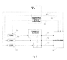
- Figure 2 represents a second particularly advantageous embodiment of the invention in which a multiplexer is linked to at least two coding devices.
- the multiplexer may be required to combine the stream of a coding device with other streams emanating from coding devices which it does not command. It also ensures the renewal of the signalling of the stream and may also ensure a scrambling function.
- the two coding devices comply with the MPEG-2 standard.
- This embodiment is in particular very advantageous within the framework of statistical multiplexing.
- the multiplexer generates an output stream of MPTS type (the acronym standing for “Multiple Program Transport Stream”) by multiplexing the various streams TS or SPTS (the acronym standing for "Single Program Transport Stream”).
- the multiplexer allocates a bit rate to each coding device in such a way that the total bit rate of all the coding devices participating in the creation of the MPTS stream does not exceed the output bit rate of the multiplexer.
- this allocation is dynamic, one speaks of statistical multiplexing.
- the invention makes it possible to ensure that, when the coding devices C1, C2,..., Cn are remote from one another, and from the multiplexer M, the maximum bit rate constraint is complied with at every instant at the input and hence at the output of the multiplexer.
- the coding devices C1, C2,..., Cn act on their bit rate, in return for a command transmitted by the multiplexer, and that the bit rate modifications emanating from the coding devices arrive at the multiplexer at precise instants, otherwise there will be bit rate overload or under-load at the multiplexer level. It is in particular necessary that this be true at every instant.
- the transport networks T1, T2,..., Tn are networks comparable to the network 2 of Figure 1, not exhibiting any jitter but a respective transit time TsC1, Tsc2,..., TsCn that is unknown and which differs from one to the other but is bounded.
- the multiplexer M is likewise a bit rate allocator. It transmits a bit rate cue to each coding device C1, C2,..., Cn, indicating the bit rate allocated to it while taking account of the complexities of the various video streams emanating from the various coding devices and the output bit rate of the multiplexer M.
- each coding device C1, C2,..., Cn
- M multiplexer
- the complexity cue represents the entropy of the video signal at the input of each coding device. For example, it may be likened to a bit rate level necessary to reach a minimum level of quality after decoding of the image sequences.
- the complexity cues are transmitted from the coding devices to the multiplexer in the SPTS stream through the networks T1 to Tn.
- these cues are synchronized with the PCRc in such a way as to guarantee that the resulting bit rates of the complexity cues remain synchronized.
- the multiplexer being required to comply with the minimum execution lag Delta-Action, the bit rates resulting from the last complexities received by the multiplexer will therefore be applied with the same delay Delta-Action by the coding device.
- the coding devices are therefore furnished with a means of anticipating their measurement of complexity by the time Delta-Action so as to obtain at any moment a bit rate that is apt for their instantaneous complexity.
- the complexity cues are transported on the networks R1 to Rn, it is probable that the complexity cues sent by the coding devices do not experience the same crossing times as the SPTS streams. This will engender an uncertainty which translates into a loss of efficiency of the statistical multiplexing mechanism (time offset between bit rate requirement and actual bit rate).
- the coding devices mark each complexity cue with the value of the PCRc field. The multiplexer is then able to "synchronize" the complexity cues mutually on the basis of the time references PCRc emitted in the SPTS streams.
- the multiplexer M transmits through the networks R1, R2,..., Rn respectively commands to the various coding devices C1, C2,..., Cn.
- the network R is a network comparable to the network 3 of Figure 1 and has a transit time TcR that is unknown and variable but bounded by TcRmax.
- the multiplexer transmits bit rate allocation cues to the various coding devices and transmits time cues to the various coding devices C1, C2,..., Cn, indicating to each coding device the instant, with respect to its own PCR, at which it must act so that the bit rate modification arrives at the required instant at the multiplexer so as to guarantee appropriate allocation and integrity of the stream at the output of the multiplexer M.
- PCRm_Action represents the instant at which the multiplexer decides on an action and Delta_Action represents the time within which this action must have effects at its input.
- PCRmi represents the value of the time reference of the multiplexing device M upon the reception of the time label of the coding device Ci.
- the method therefore avoids having to mutually synchronize the coding devices, this being the solution commonly employed in the solutions known to the person skilled in the art, and to dispense with the transit lag in the transport network, only the maximum time having to be known.
- the multiplexer therefore receives synchronous actions from the coding devices, while avoiding having to mutually synchronize them and to synchronize them with the multiplexer.
- the mechanism can also be used to carry out toggling between two coding devices, one of the coding devices switching from a zero bit rate to a non-zero bit rate and the other doing the reverse.
- the precision obtained relating to the instant of reception of the effect of the said command in the multiplexer is a packet level precision.
- the precision of the control is related to the packet jitter introduced by the intermediate multiplexer or multiplexers.
- the coding devices C1 to Cn are furnished with an ability to anticipate their complexities to a depth TsCimax + TcRimax.
- the bit rate preset returned by the multiplexer to each coding device is in phase with the bit rate requirement of the coding device. This constitutes in reality an indispensable element of the implementation once TsCimax + TcRimax exceeds 100 ms, the maximum time between two packets containing a time label.
- the anticipation of the complexities is ensured by the carrying out of a double-coding at the level of each coding device C1, C2,..., Cn.
- the first coding pass calculates the complexity to be dispatched to the multiplexer M and the second pass ensures the actual coding on the basis of the bit rate allocated by the multiplexer M.
- the minimum lag between the 2 coding passes then equals TsCimax + TcRimax.
Landscapes
- Engineering & Computer Science (AREA)
- Multimedia (AREA)
- Signal Processing (AREA)
- Data Exchanges In Wide-Area Networks (AREA)
- Time-Division Multiplex Systems (AREA)
- Compression Or Coding Systems Of Tv Signals (AREA)
- Two-Way Televisions, Distribution Of Moving Picture Or The Like (AREA)
Abstract
- means for calculating an instant of action (PCRc_Action) for the coding device at which it desires that the coding device (1, C1, C2,...,Cn) perform the said command as a function of the instant (PCRm_Action) at which it transmits the said command to the said coding device (1, C1, C2,...,Cn), of the time label (PCRc) of the data packets, of its time reference (PCRm) and of the maximum transfer time (Delta_Action) between the coding device (1, C1, C2,...,Cn) and the multiplexing device (4, M),
- means for transmitting said instant of action (PCRc_Action) and the said command to the coding device (1, C1, C2,...,Cn).
Description
- The invention relates to a device and method for multiplexing.
- The invention relates more particularly to the multiplexing devices associated with coding devices and the interaction between these devices.
- The invention applies mainly to the control of a coding device by a multiplexer, and more particularly to the coding of video data.
- Specifically, in coding systems including both a coding device and a multiplexing device, each of the devices possessing its own reference clock, it is difficult for a multiplexer to inform a coding device of the time at which it desires to receive a packet from the coding device, since it does not know the local time of the coding device. This is all the more noteworthy when the two devices are remote and the time of transit through the network separating the two devices is not constant but merely bounded.
- The invention applies also to statistical multiplexing. Actually, very often the multiplexers of streams of MPEG-2 type for example are responsible for transmitting control cues, for controlling bit rate for example, to the various coding devices. However, these coding devices are not mutually synchronized and it is therefore difficult for a multiplexer to act simultaneously on these coding devices in order that they act at precise instants and that above all their action is received at a precise instant at the level of the multiplexer. The problem is all the more considerable when the coding devices are remote from the multiplexing device or devices since in addition to the asynchronism of the coding devices, the transit time through the networks linking them to the multiplexer is different in each network. The transit time may also vary with each establishment of a new connection through the network.
- The known devices implement solutions allowing mutual synchronization between the various coding devices with the multiplexer.
- Such solutions are complex to implement, uncompetitive and exhibit a considerable convergence time.
- The invention proposes a multiplexing device which does not attempt to mutually synchronize the various coding devices but which circumvents such synchronization while making it possible to work with the various coding devices and to obtain synchronous actions at the input of the multiplexer.
- For this purpose, the invention proposes a multiplexing device able to receive data packets from at least one coding device, some of the data packets comprising a time label, said device comprising a time reference and being able to transmit commands to the said coding device. According to the invention, the device comprises:
- means for calculating an instant of action for the coding device at which it desires that the coding device perform the said command as a function of the instant at which it transmits the said command to the said coding device, of the time label of the data packets, of its time reference and of the maximum transfer time between the coding device and the multiplexing device,
- means for transmitting said instant of action and the said command to the coding device.
- In a preferred manner, the device is connected to the coding device by way of a transport network on the one hand allowing the transmission of the data packets and by way of a communication network on the other hand allowing the transmission of the commands and of the associated instants of action, the two networks having variable transit times bounded in time, the maximum transfer time between the coding device and the multiplexing device being the sum of the maximum transit times through the two networks.
- In a preferred embodiment, the means of calculation calculate the said instant of action according to the following formula:

where PCRm_Action represents the instant at which the multiplexer decides on the said action,
where Delta_Action represents the time within which the multiplexer desires to receive the effects of the said action,
with Delta_Action > Tcmax + Tsmax,
where DeltaPCRc = PCRc - PCRm,
with PCRm representing the last time reference of the multiplexing device (M) at the instant of reception of the last time label, PRCc, of a data packet. - In a preferred embodiment, the device calculates the difference between the time label of the data packets and its time reference with each reception of a data packet comprising a time label.
- In a preferred embodiment, the device is connected to at least two coding devices by way of distinct transport networks allowing the transmission of the data packets and by way of a common communication network allowing the transmission of the commands and the associated instants of action, the said device being adapted to calculate an instant of action for each coding device, in such a way that it receives synchronously the effects of the said command of the various coding devices.
- In a preferred embodiment, the device is adapted to transmit bit rate adaptation commands to the said coding devices so as to effect the dynamic bit rate allocation.
- In a preferred embodiment, the device is adapted to receive complexity cues synchronized with the time labels of the various coding devices through the said transport networks.
- In a preferred embodiment, the device is adapted to receive complexity cues from the various coding devices through the said communication networks, the complexity cues then being marked by the said time label transmitted in a data packet.
- In a preferred embodiment, the device transmits bit rate modification commands to the said coding devices (1, C1, C2,...,Cn) as a function of its bit rate of output and of coding complexities.
- In a preferred embodiment, the means of calculation calculate the said instant of action (PCRci_Action) for each coding device (1, C1, C2,...,Cn) according to the following formula:

where PCRm_Action represents the instant at which the multiplexer decides on the said action,
where Delta_Action represents the time within which the multiplexer desires to receive the effects of the said action,
with Delta_Action > Max(Tscimax) + Max(TcRimax),
where DeltaPCRci = PCRci - PCRmi,
with PCRmi representing the time reference of the multiplexing device (M) upon the reception of the time label, PRCc of each coding device. - The invention also relates to a method of multiplexing in a multiplexing device, able to receive data packets from at least one coding device, some of the data packets comprising a time label, the said device comprising a time reference, the said method comprising a step of transmitting commands to the said coding device, characterized in that it comprises the steps of:
- calculating an instant of action at which it desires that the coding device perform the said command as a function of the instant at which it desires to receive the effects of the said command, of the time label of the data packets, of its time reference and of the maximum transfer time between the coding device and the multiplexing device,
- means of transmitting the said instant and the said command to the coding device.
- The invention will be better understood and illustrated by means of wholly nonlimiting, advantageous exemplary modes of embodiment and implementation, with reference to the appended figures in which:
- Figure 1 represents an exemplary system comprising a multiplexing device according to the invention linked to at least one remote coding device,
- Figure 2 represents an exemplary system comprising a multiplexing device according to the invention linked to several remote coding devices.
- The modules represented are functional units, which may or may not correspond to physically distinguishable units. For example, these modules or some of them may be grouped together in a single component, or constitute functionalities of one and the same piece of software. Conversely, some modules may possibly be composed of separate physical entities.
- The
coding device 1 represents a coding device in accordance with the MPEG-2 standard. It produces data packets in the MPEG-2 TS format (TS: the acronym standing for "transport stream"). - In other embodiments, it may also comply with the MPEG-4 AVC standard, or with any other standard.
- The
coding device 1 is linked to a temporal multiplexing device 4 through atransport network 2. The multiplexer 4 is also linked to other coding devices. - The
transport network 2 is a network of WAN type (the acronym standing for "Wide Area Network"). Typically, thenetwork 2 is a packet switching network which is furnished with a jitter correction mechanism, such as for example ATM. - The transfer time (Ts) through this
network 2 is constant for a given link, unknown but bounded by a maximum value Tsmax. It is different for all the links of the network and becomes constant in the steady state. - The
coding device 1 possesses a PCR counter in accordance with the ISO/IEC/13818-1 standard incremented by a clock at 27 Mhz and sends out data packets some of which possess a time label (PCRc). This clock is derived from the incoming video timing in the case of acoding device 1 in accordance with the MPEG-2 standard. PCR signifying program reference clock (PCR being the acronym for "Program Clock Reference"). - The multiplexer 4 also possesses a PCR counter organized identically to the PCRc counter and incremented by a clock at 27 Mhz. The clocks of the multiplexer and of the coding device are asynchronous and uncorrelated, the two counters therefore have different values whose difference alters over time as a function of the drifting of the two clocks, each oscillator providing the said clock having a non-zero precision.
- The
coding device 1 regularly sends a packet carrying the value of its PCR in accordance with the ISO/IEC/13818-1 norm. This norm provides for a packet transporting a PCR packet at least every 0.1 seconds. - When the multiplexer 4 wishes to send a message for the attention of the
coding device 1, it transfers the message to it through the intermediary of an inter-equipment network 3. Such a network 3 commonly used is for example a network of WAN type. - The network 3 is also a network whose maximum transfer time (Tc)Tcmax is known, it may exhibit jitter.
- In other embodiments, the
networks 2 and 3 may be merged into one, when thenetwork 2 is bidirectional. - The multiplexer 4 receives data packets TS from the
coding device 1. - With each reception of a packet transporting a PCR of the coding device (PCRc), the multiplexer calculates the time offset between its own PCR, of value PCRm at this instant of reception and that of the coding device PCRc:

This offset does not in fact represent the true time offset between the multiplexer 4 and thecoding device 1. For this it would be necessary to take into account the transit time Ts through the network. The invention makes it possible to dispense with this knowledge. - The coding device is ahead by Ts, the transit time through the network, which is unknown, but bounded by Tsmax. That is to say the coding device is at the time PCRc + Ts.
- Given that the offset between the 27 Mhz clocks used in the coding device and in the multiplexer altering as a function of the sensitivity of the oscillators used to produce the 27 Mhz clocks, it is necessary to recalculate deltaPRCc with each reception of a new value of PCRc. The value of deltaPCRc is therefore updated regularly in the multiplexer.
- The multiplexer 4 knowing its time offset between its own PCR (PCRm) and that of the coding device (PCRc), it can dispatch dated orders to the
coding device 1 while indicating a value referenced to the PCRc and hence understandable to the latter. - The multiplexer desiring an action of the coding device whose effect at the input of the multiplexer must occur within a time Delta_Action, indicates the following value to the coding device:

PCRm_Action represents the value of the time reference of the multiplexer at the instant at which it decides on an action. - In order for the action to be able to be carried out in time by the coding device, it is necessary that the command arrive before the deadline of the value PCRc_Action. Considering that the command may take up to Tcmax to reach the coding device on the one hand and that on the other hand the PCR of the coding device may be up to Tsmax seconds ahead, it is necessary to have:

- In this way, the multiplexer 4 receives at the instant PCRm_Action + Delta_Action the cues pertaining to the command or the effects of the command that it had transferred to the
coding device 1, without synchronizing itself with thecoding device 1 using complex mechanisms of PLL type (the acronym standing for "Phase Lock Loop"). - The invention is particularly advantageous in the case where the multiplexer is synchronized with a modulator situated downstream. When the modulator is informed by the transmission network of a disturbance, for example a storm, the modulator can request the multiplexer to modify its useful bit rate since the network disturbances are considerable, the error rate will increase and it is therefore necessary to modify the error correcting codes. In this case, the multiplexer transmits a command to the coding device situated upstream, indicating for example the new bit rate required and the instant at which it desires that the coding device act.
- The multiplexer can then synchronize to the packet ready the bit rate change order with the toggling of the mode of error correction of the modulator situated downstream. For example, the multiplexer can generate an order to the modulator at the precise moment at which the PCRc emanating from the coding device reaches the value that served for the dating of the coding device bit rate change order.
- Among the commands which may be cited, there may for example be mentioned the addition or the removal of components associated with a video stream, for example an audio component.
- Figure 2 represents a second particularly advantageous embodiment of the invention in which a multiplexer is linked to at least two coding devices.
- The multiplexer may be required to combine the stream of a coding device with other streams emanating from coding devices which it does not command. It also ensures the renewal of the signalling of the stream and may also ensure a scrambling function.
- The two coding devices comply with the MPEG-2 standard.
- This embodiment is in particular very advantageous within the framework of statistical multiplexing.
- The multiplexer generates an output stream of MPTS type (the acronym standing for "Multiple Program Transport Stream") by multiplexing the various streams TS or SPTS (the acronym standing for "Single Program Transport Stream").
- The multiplexer allocates a bit rate to each coding device in such a way that the total bit rate of all the coding devices participating in the creation of the MPTS stream does not exceed the output bit rate of the multiplexer. When this allocation is dynamic, one speaks of statistical multiplexing.
- The invention makes it possible to ensure that, when the coding devices C1, C2,..., Cn are remote from one another, and from the multiplexer M, the maximum bit rate constraint is complied with at every instant at the input and hence at the output of the multiplexer.
- For this purpose, it is necessary that the coding devices C1, C2,..., Cn act on their bit rate, in return for a command transmitted by the multiplexer, and that the bit rate modifications emanating from the coding devices arrive at the multiplexer at precise instants, otherwise there will be bit rate overload or under-load at the multiplexer level. It is in particular necessary that this be true at every instant.
- The transport networks T1, T2,..., Tn are networks comparable to the
network 2 of Figure 1, not exhibiting any jitter but a respective transit time TsC1, Tsc2,..., TsCn that is unknown and which differs from one to the other but is bounded. - The multiplexer M is likewise a bit rate allocator. It transmits a bit rate cue to each coding device C1, C2,..., Cn, indicating the bit rate allocated to it while taking account of the complexities of the various video streams emanating from the various coding devices and the output bit rate of the multiplexer M.
- The complexity cues serving in the calculation of the bit rates are transmitted by each coding device (C1, C2,..., Cn) to the multiplexer (M):
- 1 - either by the networks T1, T2,..., Tn in the TS stream in the form of private data
- 2 - or by the networks R1 to Rn as long as they are bidirectional.
- The complexity cue represents the entropy of the video signal at the input of each coding device. For example, it may be likened to a bit rate level necessary to reach a minimum level of quality after decoding of the image sequences.
- In a preferred manner, the complexity cues are transmitted from the coding devices to the multiplexer in the SPTS stream through the networks T1 to Tn. In this case, these cues are synchronized with the PCRc in such a way as to guarantee that the resulting bit rates of the complexity cues remain synchronized. The multiplexer being required to comply with the minimum execution lag Delta-Action, the bit rates resulting from the last complexities received by the multiplexer will therefore be applied with the same delay Delta-Action by the coding device. In an optimized embodiment, the coding devices are therefore furnished with a means of anticipating their measurement of complexity by the time Delta-Action so as to obtain at any moment a bit rate that is apt for their instantaneous complexity.
- In the case where the complexity cues are transported on the networks R1 to Rn, it is probable that the complexity cues sent by the coding devices do not experience the same crossing times as the SPTS streams. This will engender an uncertainty which translates into a loss of efficiency of the statistical multiplexing mechanism (time offset between bit rate requirement and actual bit rate). To remedy this defect, the coding devices mark each complexity cue with the value of the PCRc field. The multiplexer is then able to "synchronize" the complexity cues mutually on the basis of the time references PCRc emitted in the SPTS streams.
- The statistical multiplexing mechanism is described in French Patent Application 9713975 filed on 6 November 1997 in the name of the company Thomson Broadcast Systems.
- The multiplexer M transmits through the networks R1, R2,..., Rn respectively commands to the various coding devices C1, C2,..., Cn. The network R is a network comparable to the network 3 of Figure 1 and has a transit time TcR that is unknown and variable but bounded by TcRmax.
- The multiplexer transmits bit rate allocation cues to the various coding devices and transmits time cues to the various coding devices C1, C2,..., Cn, indicating to each coding device the instant, with respect to its own PCR, at which it must act so that the bit rate modification arrives at the required instant at the multiplexer so as to guarantee appropriate allocation and integrity of the stream at the output of the multiplexer M.
- The multiplexer therefore calculates as indicated with reference to Figure 2, for each coding device a time PCRc_Action such that:

with DeltaPCRci = PCRci-PCRmi - PCRm_Action represents the instant at which the multiplexer decides on an action and Delta_Action represents the time within which this action must have effects at its input.
- PCRmi represents the value of the time reference of the multiplexing device M upon the reception of the time label of the coding device Ci.
- And for each coding device:

- The method therefore avoids having to mutually synchronize the coding devices, this being the solution commonly employed in the solutions known to the person skilled in the art, and to dispense with the transit lag in the transport network, only the maximum time having to be known.
- It also avoids storage of the signal for the purposes of resynchronizing the effects of the actions at the multiplexer level, only the control messages are stored in a buffer memory while awaiting the deadline of the respective PCRcs.
- The multiplexer therefore receives synchronous actions from the coding devices, while avoiding having to mutually synchronize them and to synchronize them with the multiplexer.
- The mechanism can also be used to carry out toggling between two coding devices, one of the coding devices switching from a zero bit rate to a non-zero bit rate and the other doing the reverse.
- The precision obtained relating to the instant of reception of the effect of the said command in the multiplexer is a packet level precision.
- When the
network 2 between the coding device and the multiplexing device 4, with reference to Figure 1, comprises at least one intermediate multiplexer, the precision of the control is related to the packet jitter introduced by the intermediate multiplexer or multiplexers. - In the case of statistical multiplexing, in an optimized form, the coding devices C1 to Cn are furnished with an ability to anticipate their complexities to a depth TsCimax + TcRimax. Thus, the bit rate preset returned by the multiplexer to each coding device is in phase with the bit rate requirement of the coding device. This constitutes in reality an indispensable element of the implementation once TsCimax + TcRimax exceeds 100 ms, the maximum time between two packets containing a time label.
- In practice, the anticipation of the complexities is ensured by the carrying out of a double-coding at the level of each coding device C1, C2,..., Cn. The first coding pass calculates the complexity to be dispatched to the multiplexer M and the second pass ensures the actual coding on the basis of the bit rate allocated by the multiplexer M. In this implementation, the minimum lag between the 2 coding passes then equals TsCimax + TcRimax.
Claims (11)
- Multiplexing device (4, M) able to receive data packets from at least one coding device (1, C1, C2,...,Cn), some of the data packets comprising a time label (PCRc), said device comprising a time reference (PCRm) and being able to transmit commands to the said coding device (1, C1, C2,...,Cn), characterized in that it comprises:- means for calculating an instant of action (PCRc_Action) for the coding device at which it desires that the coding device (1, C1, C2,...,Cn) perform the said command as a function of the instant (PCRm_Action) at which it transmits the said command to the said coding device (1, C1, C2,...,Cn), of the time label (PCRc) of the data packets, of its time reference (PCRm) and of the maximum transfer time (Delta_Action) between the coding device (1, C1, C2,...,Cn) and the multiplexing device (4, M),- means for transmitting said instant of action (PCRc_Action) and the said command to the coding device (1, C1, C2,...,Cn).
- Device according to Claim 1 characterized in that it is connected to the coding device (1, C1, C2,...,Cn) by way of a transport network (2, T1, T2,..., Tn) on the one hand allowing the transmission of the data packets and by way of a communication network (3, R) on the other hand allowing the transmission of the commands and of the associated instants of action (PCRci_Action), the two networks (2, T1, T2,..., Tn) having variable transit times (TsCi) bounded in time, the maximum transfer time between the coding device (1, C1, C2,...,Cn) and the multiplexing device (4, M) being the sum of the maximum transit times (Tcmax, Tsmax) through the two networks (2, T1, T2,..., Tn, 3, R).
- Device according to one of Claims 1 or 2 characterized in that the means of calculation calculate the said instant of action (PCRc_Action) according to the following formula:

where PCRm_Action represents the instant at which the multiplexer decides on the said action,
where Delta_Action represents the time within which the multiplexer desires to receive the effects of the said action,
with Delta_Action > Tcmax + Tsmax,
where DeltaPCRc = PCRc - PCRm,
with PCRm representing the last time reference of the multiplexing device (M) at the instant of reception of the last time label, PRCc, of a data packet. - Device according to Claim 3 characterized in that it calculates the difference (DeltaPCRc) between the time label (PCRc) of the data packets and its time reference (PCRm) with each reception of a data packet comprising a time label (PCRc).
- Device according to Claim 1 characterized in that it is connected to at least two coding devices (1, C1, C2,...,Cn) by way of distinct transport networks (T1, T2,..., Tn) allowing the transmission of the data packets and by way of a common communication network (R) allowing the transmission of the commands and the associated instants of action (PCRci_Action), the said device being adapted to calculate an instant of action (PCRci_Action) for each coding device (1, C1, C2,...,Cn), in such a way that it receives synchronously the effects of the said command of the various coding devices (1, C1, C2,...,Cn).
- Device according to Claim 5 characterized in that it is adapted to transmit bit rate adaptation commands to the said coding devices (1, C1, C2,...,Cn) so as to effect dynamic bit rate allocation.
- Device according to Claim 6 characterized in that it is adapted to receive complexity cues synchronized with the time labels of the various coding devices through the said transport networks.
- Device according to Claim 6 characterized in that it is adapted to receive complexity cues from the various coding devices through the said communication networks, the complexity cues then being marked by the said time label transmitted in a data packet.
- Device according to one of Claims 6 to 8 characterized in that it transmits bit rate modification commands to the said coding devices (1, C1, C2,...,Cn) as a function of its bit rate of output and of coding complexities.
- Device according to one of Claims 5 to 7 characterized in that the means of calculation calculate the said instant of action (PCRci_Action) for each coding device (1, C1, C2,...,Cn) according to the following formula:

where PCRm_Action represents the instant at which the multiplexer decides on the said action,
where Delta_Action represents the time within which the multiplexer desires to receive the effects of the said action,
with Delta_Action > Max(Tscimax) + Max(TcRimax),
where DeltaPCRci = PCRci - PCRmi,
with PCRmi representing the time reference of the multiplexing device (M) upon the reception of the time label, PRCc of each coding device. - Method of multiplexing in a multiplexing device (4, M), able to receive data packets from at least one coding device, some of the data packets comprising a time label (PCRc), the said device comprising a time reference (PCRm), the said method comprising a step of transmitting commands to the said coding device (1, C1, C2,...,Cn), characterized in that it comprises the steps of:- calculating an instant of action (PCRc_Action) at which it desires that the coding device (1, C1, C2,..., Cn) perform the said command as a function of the instant at which it desires to receive the effects of the said command, of the time label (PCRc) of the data packets, of its time reference (PCRm) and of the maximum transfer time (Delta_Action) between the coding device (1, C1, C2,..., Cn) and the multiplexing device (4, M),- means of transmitting the said instant (PCRc_Action) and the said command to the coding device (1, C1, C2,..., Cn).
Applications Claiming Priority (1)
| Application Number | Priority Date | Filing Date | Title |
|---|---|---|---|
| FR0451394A FR2872666A1 (en) | 2004-07-01 | 2004-07-01 | DEVICE AND METHOD FOR MULTIPLEXING ASSOCIATED WITH AN ENCODING DEVICE |
Publications (1)
| Publication Number | Publication Date |
|---|---|
| EP1624693A1 true EP1624693A1 (en) | 2006-02-08 |
Family
ID=34940218
Family Applications (1)
| Application Number | Title | Priority Date | Filing Date |
|---|---|---|---|
| EP05105534A Withdrawn EP1624693A1 (en) | 2004-07-01 | 2005-06-22 | Device and method for multiplexing data from coding devices via a communication network |
Country Status (8)
| Country | Link |
|---|---|
| US (1) | US7561568B2 (en) |
| EP (1) | EP1624693A1 (en) |
| JP (1) | JP4758698B2 (en) |
| KR (1) | KR101182078B1 (en) |
| CN (1) | CN1716831B (en) |
| AU (1) | AU2005202779B2 (en) |
| FR (1) | FR2872666A1 (en) |
| MX (1) | MXPA05007004A (en) |
Families Citing this family (1)
| Publication number | Priority date | Publication date | Assignee | Title |
|---|---|---|---|---|
| US20150312601A1 (en) * | 2014-04-28 | 2015-10-29 | Magnum Semiconductor, Inc. | Methods and apparatuses including a statistical multiplexer with multiple channel rate control |
Citations (12)
| Publication number | Priority date | Publication date | Assignee | Title |
|---|---|---|---|---|
| EP0515101A2 (en) * | 1991-05-23 | 1992-11-25 | AT&T Corp. | Buffer control for variable bit-rate channel |
| US5477542A (en) * | 1993-03-30 | 1995-12-19 | Hitachi, Ltd. | Method and appartus for controlling multimedia information communication |
| JPH10271081A (en) * | 1997-03-24 | 1998-10-09 | Nec Corp | Mpeg2-ts multiplexing method and device |
| EP0915623A1 (en) * | 1997-11-06 | 1999-05-12 | Thomson Broadcast Systems | Device for processing coded video data and systems for distributing programmes using such a device |
| GB2334860A (en) * | 1997-10-15 | 1999-09-01 | Sony Corp | Video data multiplexer, video data multiplexing control method, method and app aratus for multiplexing encoded stream, and encoding method and apparatus |
| JP2000134259A (en) * | 1998-10-26 | 2000-05-12 | Sumitomo Electric Ind Ltd | Transmission method and transmission device |
| JP2002208904A (en) * | 2001-01-10 | 2002-07-26 | Sony Corp | Digital signal multiplexer |
| US20020103919A1 (en) * | 2000-12-20 | 2002-08-01 | G. Wyndham Hannaway | Webcasting method and system for time-based synchronization of multiple, independent media streams |
| US20030007516A1 (en) * | 2001-07-06 | 2003-01-09 | Yuri Abramov | System and method for the application of a statistical multiplexing algorithm for video encoding |
| US20030152032A1 (en) * | 2002-02-14 | 2003-08-14 | Kddi Corporation | Video information transmission system, and apparatus and program used for video information transmission system |
| US6628677B1 (en) * | 1998-02-28 | 2003-09-30 | Sony Corporation | Coding and multiplexing apparatus and method |
| EP1406452A2 (en) * | 2002-10-03 | 2004-04-07 | NTT DoCoMo, Inc. | Video signal encoding and decoding method |
Family Cites Families (12)
| Publication number | Priority date | Publication date | Assignee | Title |
|---|---|---|---|---|
| US5533021A (en) * | 1995-02-03 | 1996-07-02 | International Business Machines Corporation | Apparatus and method for segmentation and time synchronization of the transmission of multimedia data |
| US5640388A (en) * | 1995-12-21 | 1997-06-17 | Scientific-Atlanta, Inc. | Method and apparatus for removing jitter and correcting timestamps in a packet stream |
| EP0823823A3 (en) * | 1996-08-07 | 2001-02-14 | Matsushita Electric Industrial Co., Ltd. | Digital broadcasting system |
| JPH10271061A (en) | 1997-03-25 | 1998-10-09 | Mitsubishi Electric Corp | Digital wireless telephone |
| JP3978814B2 (en) * | 1997-07-02 | 2007-09-19 | ソニー株式会社 | Transmitting apparatus and method, receiving apparatus, and transmitting apparatus |
| JPH11252556A (en) * | 1998-02-28 | 1999-09-17 | Sony Corp | Code multiplexing apparatus and code multiplexing method |
| US6493832B1 (en) * | 1999-03-17 | 2002-12-10 | Sony Corporation | Communication apparatus which handles a time stamp |
| JP4193297B2 (en) * | 1999-08-04 | 2008-12-10 | ソニー株式会社 | COMMUNICATION DEVICE AND METHOD, COMMUNICATION SYSTEM, AND RECORDING MEDIUM |
| JP2001177568A (en) * | 1999-12-16 | 2001-06-29 | Matsushita Electric Ind Co Ltd | Stream multiplexer |
| JP2001251616A (en) * | 2000-03-02 | 2001-09-14 | Media Glue Corp | Method and device for converting multiplexed sound/ moving picture compressing-coded signal, and medium recorded with conversion program |
| JP2001257664A (en) * | 2000-03-14 | 2001-09-21 | Nec Corp | Clock frequency synchronous control circuit in digital broadcast receiver |
| US6959042B1 (en) * | 2001-10-01 | 2005-10-25 | Cisco Technology, Inc. | Methods and apparatus for measuring compressed video signals and applications to statistical remultiplexing |
-
2004
- 2004-07-01 FR FR0451394A patent/FR2872666A1/en active Pending
-
2005
- 2005-06-16 US US11/154,915 patent/US7561568B2/en active Active
- 2005-06-16 CN CN2005100781717A patent/CN1716831B/en not_active Expired - Fee Related
- 2005-06-22 EP EP05105534A patent/EP1624693A1/en not_active Withdrawn
- 2005-06-24 AU AU2005202779A patent/AU2005202779B2/en not_active Ceased
- 2005-06-27 MX MXPA05007004A patent/MXPA05007004A/en active IP Right Grant
- 2005-06-30 KR KR1020050058356A patent/KR101182078B1/en not_active Expired - Fee Related
- 2005-07-01 JP JP2005193554A patent/JP4758698B2/en not_active Expired - Fee Related
Patent Citations (12)
| Publication number | Priority date | Publication date | Assignee | Title |
|---|---|---|---|---|
| EP0515101A2 (en) * | 1991-05-23 | 1992-11-25 | AT&T Corp. | Buffer control for variable bit-rate channel |
| US5477542A (en) * | 1993-03-30 | 1995-12-19 | Hitachi, Ltd. | Method and appartus for controlling multimedia information communication |
| JPH10271081A (en) * | 1997-03-24 | 1998-10-09 | Nec Corp | Mpeg2-ts multiplexing method and device |
| GB2334860A (en) * | 1997-10-15 | 1999-09-01 | Sony Corp | Video data multiplexer, video data multiplexing control method, method and app aratus for multiplexing encoded stream, and encoding method and apparatus |
| EP0915623A1 (en) * | 1997-11-06 | 1999-05-12 | Thomson Broadcast Systems | Device for processing coded video data and systems for distributing programmes using such a device |
| US6628677B1 (en) * | 1998-02-28 | 2003-09-30 | Sony Corporation | Coding and multiplexing apparatus and method |
| JP2000134259A (en) * | 1998-10-26 | 2000-05-12 | Sumitomo Electric Ind Ltd | Transmission method and transmission device |
| US20020103919A1 (en) * | 2000-12-20 | 2002-08-01 | G. Wyndham Hannaway | Webcasting method and system for time-based synchronization of multiple, independent media streams |
| JP2002208904A (en) * | 2001-01-10 | 2002-07-26 | Sony Corp | Digital signal multiplexer |
| US20030007516A1 (en) * | 2001-07-06 | 2003-01-09 | Yuri Abramov | System and method for the application of a statistical multiplexing algorithm for video encoding |
| US20030152032A1 (en) * | 2002-02-14 | 2003-08-14 | Kddi Corporation | Video information transmission system, and apparatus and program used for video information transmission system |
| EP1406452A2 (en) * | 2002-10-03 | 2004-04-07 | NTT DoCoMo, Inc. | Video signal encoding and decoding method |
Non-Patent Citations (3)
| Title |
|---|
| PATENT ABSTRACTS OF JAPAN vol. 1999, no. 01 29 January 1999 (1999-01-29) * |
| PATENT ABSTRACTS OF JAPAN vol. 2000, no. 08 6 October 2000 (2000-10-06) * |
| PATENT ABSTRACTS OF JAPAN vol. 2002, no. 11 6 November 2002 (2002-11-06) * |
Also Published As
| Publication number | Publication date |
|---|---|
| KR20060049714A (en) | 2006-05-19 |
| US7561568B2 (en) | 2009-07-14 |
| AU2005202779B2 (en) | 2009-12-03 |
| MXPA05007004A (en) | 2006-04-27 |
| CN1716831A (en) | 2006-01-04 |
| JP4758698B2 (en) | 2011-08-31 |
| CN1716831B (en) | 2011-02-16 |
| US20060002410A1 (en) | 2006-01-05 |
| AU2005202779A1 (en) | 2006-01-19 |
| FR2872666A1 (en) | 2006-01-06 |
| JP2006020328A (en) | 2006-01-19 |
| KR101182078B1 (en) | 2012-09-11 |
Similar Documents
| Publication | Publication Date | Title |
|---|---|---|
| US5623483A (en) | Synchronization system for networked multimedia streams | |
| US8396159B2 (en) | Message synchronization over a stochastic network | |
| CN102934379B (en) | Node and system for synchronous network | |
| US9307298B2 (en) | System and method for video statistical multiplexing adapting to internet protocol networks | |
| CN100448217C (en) | Realization of clock synchronization in information packet network by using SRTS and having no need of common network clock | |
| JP2018042019A (en) | Video switching system | |
| WO2005076513A1 (en) | Jitter correcting apparatus capable of ensuring synchronism between transmitter apparatus and receiver apparatus | |
| EA027102B1 (en) | Method and system for deterministic re-multiplexing of transport streams in sfn network | |
| US11653041B2 (en) | Jitter management in a statistical multiplexer employing an IP network | |
| US7561568B2 (en) | Device and method for multiplexing associated with a coding device | |
| US20030002540A1 (en) | MPEG data packet transmission through an ATM network with jitter free decoding | |
| CN101103566B (en) | Method of transmitting mpeg streams over ip and corresponding device, receiving method and receiver | |
| JP2007518333A (en) | Introducing jitter in data transmission systems | |
| US10951390B2 (en) | Two-stage IP de-jitter algorithm in a multiplexer for a group of statistically multiplexed single program transport streams | |
| JP4092705B2 (en) | Stream transmitting apparatus, receiving apparatus, and transmission / reception method | |
| JP3736396B2 (en) | Stream transmitting apparatus and receiving apparatus | |
| US8218577B2 (en) | Secure mechanism for transmitting counter value in the context of transmission of a synchronizing signal in a packet network | |
| JPH08307863A (en) | Video encoding information transmission / reception synchronization method |
Legal Events
| Date | Code | Title | Description |
|---|---|---|---|
| PUAI | Public reference made under article 153(3) epc to a published international application that has entered the european phase |
Free format text: ORIGINAL CODE: 0009012 |
|
| AK | Designated contracting states |
Kind code of ref document: A1 Designated state(s): AT BE BG CH CY CZ DE DK EE ES FI FR GB GR HU IE IS IT LI LT LU MC NL PL PT RO SE SI SK TR |
|
| AX | Request for extension of the european patent |
Extension state: AL BA HR LV MK YU |
|
| 17P | Request for examination filed |
Effective date: 20060802 |
|
| AKX | Designation fees paid |
Designated state(s): DE ES FR GB IT |
|
| 17Q | First examination report despatched |
Effective date: 20080215 |
|
| RAP1 | Party data changed (applicant data changed or rights of an application transferred) |
Owner name: THOMSON LICENSING |
|
| RAP1 | Party data changed (applicant data changed or rights of an application transferred) |
Owner name: FRANCE BREVETS, |
|
| STAA | Information on the status of an ep patent application or granted ep patent |
Free format text: STATUS: THE APPLICATION IS DEEMED TO BE WITHDRAWN |
|
| 18D | Application deemed to be withdrawn |
Effective date: 20161122 |