EP1624224B1 - A method for infusing a region of strands in a cable with liquid potting compound - Google Patents
A method for infusing a region of strands in a cable with liquid potting compound Download PDFInfo
- Publication number
- EP1624224B1 EP1624224B1 EP04254762A EP04254762A EP1624224B1 EP 1624224 B1 EP1624224 B1 EP 1624224B1 EP 04254762 A EP04254762 A EP 04254762A EP 04254762 A EP04254762 A EP 04254762A EP 1624224 B1 EP1624224 B1 EP 1624224B1
- Authority
- EP
- European Patent Office
- Prior art keywords
- strands
- region
- potting compound
- anchor
- cable
- Prior art date
- Legal status (The legal status is an assumption and is not a legal conclusion. Google has not performed a legal analysis and makes no representation as to the accuracy of the status listed.)
- Expired - Lifetime
Links
- 239000007788 liquid Substances 0.000 title claims abstract description 45
- 238000004382 potting Methods 0.000 title claims abstract description 45
- 150000001875 compounds Chemical class 0.000 title claims abstract description 44
- 238000000034 method Methods 0.000 title claims abstract description 20
- 238000002347 injection Methods 0.000 claims description 7
- 239000007924 injection Substances 0.000 claims description 7
- 238000007789 sealing Methods 0.000 claims description 6
- 239000007787 solid Substances 0.000 claims description 6
- 230000007704 transition Effects 0.000 claims 1
- 238000013022 venting Methods 0.000 abstract description 2
- 238000001802 infusion Methods 0.000 description 5
- 230000008878 coupling Effects 0.000 description 3
- 238000010168 coupling process Methods 0.000 description 3
- 238000005859 coupling reaction Methods 0.000 description 3
- 238000013459 approach Methods 0.000 description 2
- 239000000835 fiber Substances 0.000 description 2
- 238000009434 installation Methods 0.000 description 2
- 239000004593 Epoxy Substances 0.000 description 1
- 238000007605 air drying Methods 0.000 description 1
- 239000003054 catalyst Substances 0.000 description 1
- 239000000470 constituent Substances 0.000 description 1
- 238000001816 cooling Methods 0.000 description 1
- 238000007598 dipping method Methods 0.000 description 1
- 125000003700 epoxy group Chemical group 0.000 description 1
- 229910052751 metal Inorganic materials 0.000 description 1
- 239000002184 metal Substances 0.000 description 1
- 150000002739 metals Chemical class 0.000 description 1
- 238000000465 moulding Methods 0.000 description 1
- 238000010422 painting Methods 0.000 description 1
- 229920000647 polyepoxide Polymers 0.000 description 1
- 229920005989 resin Polymers 0.000 description 1
- 239000011347 resin Substances 0.000 description 1
- 229920001169 thermoplastic Polymers 0.000 description 1
- 229920001187 thermosetting polymer Polymers 0.000 description 1
- 239000004416 thermosoftening plastic Substances 0.000 description 1
- 238000012800 visualization Methods 0.000 description 1
Images







Classifications
-
- F—MECHANICAL ENGINEERING; LIGHTING; HEATING; WEAPONS; BLASTING
- F16—ENGINEERING ELEMENTS AND UNITS; GENERAL MEASURES FOR PRODUCING AND MAINTAINING EFFECTIVE FUNCTIONING OF MACHINES OR INSTALLATIONS; THERMAL INSULATION IN GENERAL
- F16G—BELTS, CABLES, OR ROPES, PREDOMINANTLY USED FOR DRIVING PURPOSES; CHAINS; FITTINGS PREDOMINANTLY USED THEREFOR
- F16G11/00—Means for fastening cables or ropes to one another or to other objects; Caps or sleeves for fixing on cables or ropes
- F16G11/04—Means for fastening cables or ropes to one another or to other objects; Caps or sleeves for fixing on cables or ropes with wedging action, e.g. friction clamps
- F16G11/042—Means for fastening cables or ropes to one another or to other objects; Caps or sleeves for fixing on cables or ropes with wedging action, e.g. friction clamps using solidifying liquid material forming a wedge
Definitions
- This invention relates to the field of cables and ropes. More specifically, the invention comprises a process for infusing liquid potting compound into the strands of a rope or cable prior to affixing an anchor or for other uses.
- Anchors typically have an expanding internal passage or some type of interlocking features, such as ridges.
- the strands proximate the end of a cable are wetted with liquid potting compound.
- the wetted strands are then placed within the internal passage of the anchor.
- the potting compound then hardens to form a solid, thereby locking a length of strands into the anchor.
- the anchor, along with the contained strands and solid potting compound will be referred to as a "termination.”
- potting compound generally refers to any liquid which can be transformed into a solid (such as by air-drying, cooling, reacting with a catalyst, etc.).
- examples include thermoplastics, molten metals, thermoset plastics, and reactive compounds (such as two-part epoxies).
- Two methods of infusing liquid potting compound into the strands of a cable are in common use. These are: (1) Pulling an anchor into its final position around the exposed strands and pouring the liquid potting compound into an open end of the anchor; or (2) Infusing the exposed strands with liquid potting compound, then pulling the anchor into its final position (The infusion is typically accomplished via painting on the liquid potting compound or dipping the exposed strands into a vat of liquid potting compound).
- the potting compound may fail to fully infuse the strands.
- both approaches must generally be performed manually, resulting in drastic variations from termination to termination.
- a method for infusing a region of strands in a cable with liquid potting compound comprising:
- a second venting passage is preferably employed, so that the liquid potting compound flows through the mold without trapping any air pockets. After infusion and before the liquid potting compound hardens, the mold is opened.
- FIG. 1 shows four cables 10 with exposed strands in varying configurations.
- the far left example shows core strands 12 exposed and ready for potting in an undisturbed state. Proceeding to the right, the next example shows the exposed strands being compressed to form fanned strands 14. The next example shows the exposed strands being splayed to form conical strands 16. The far right example shows the strands being splayed apart further to form radially fanned strands 44. All these examples, as well as others, may be employed prior to infusing the exposed strands with liquid potting resin.
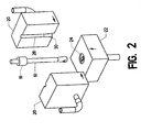
- FIG. 2 shows one embodiment of the present invention.
- Anchor 18 is placed on cable 10 and pulled away from the exposed end strands to the position shown.
- Cable 10 is then positioned between the upper mold portions 20 (In the example shown, two mold portions are used.
- the upper portion of the mold can also be split into three or more portions).
- Each upper mold portion 20 preferably includes a cable cavity 28 and a strand cavity 30.
- Mold base 22 lies beneath cable 10. The two upper mold portions 20 clamp securely together, as indicated by the arrows. This action results in cable 10 being held tightly within the internal passages in the two upper mold portions.
- Mold base 22 then moves upward to seal off the bottom of cable 10.
- mold base 22 then moves upward to seal off the bottom of cable 10.
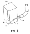
- FIG. 3 is a sectional view of one of the two upper mold portions 20.
- infeed runner 32 connects liquid coupling 34 with strand cavity 30.
- infeed runner 32 When clamped in place, preferably pressurized liquid potting compound is forced through infeed runner 32 where it emerges in and around the exposed strands of cable 10. Cable cavity 28 is clamped securely around the rest of cable 10, thereby preventing the liquid potting compound from diffusing upward beyond the exposed end strands.
- a fairly loose fit can be provided around cable 10 so that entrapped air can vent past cable 10.
- the second upper molding portion can be equipped with a corresponding infeed runner. Additional infeed runners could also be provided in the mold base. An infeed runner could be placed at virtually any location and in any orientation within strand cavity 30.
- FIG. 4 is an isometric section view of mold base 22. Its upper surface opens into strand cavity 24 (A flat upper surface having no recess can also be used). A conically shaped separator 26 may be provided in the middle in order to splay the exposed strands of the cable when mold base 22 is moved up into position.
- Mold base 22 is preferably equipped with one or more liquid vents 36. These connect to vent coupling 38. In operation, the mold parts are clamped together to form the enclosed strand cavity 30. Liquid potting compound is then forced under pressure into the mold through infeed runners 32. Liquid vents 36 allow air within the mold cavity to escape. Eventually, liquid potting compound completely fills the cavity and flows out through liquid vents 36. A vacuum may be applied to vent coupling 38 in order to promote faster flow or more complete liquid potting compound infusion.
- the infeed runners and liquid vents can be reversed so that the liquid potting compound flows from the bottom to the top. Vacuum and pressure can also be used interchangeably to create the desired flow.
- the runners and vents have been shown as circular, those skilled in the art will know that they could also be made with an oval cross section, a square cross section, or any other desired shape.
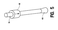
- FIG. 5 shows cable 10 after its end strands have been infused with liquid potting compound within the mold.
- the end strands are now denoted as infused strands 40.
- Anchor 18 is then moved down in the direction shown until it encloses the infused end strands (or otherwise mechanically interlocks).
- Anchor 18 is shown in its final position in FIG. 6 . It remains in this position while the liquid potting compound hardens into a solid, thereby forming a completed termination.
- anchor 18 can be slid into position from the opposite end of the cable after the liquid potting compound is applied.
- FIG. 7 shows the application of the devices and processes disclosed to an assembly line.
- a series of cables 10 - with anchors 18 in an appropriate position are sequentially fed along the line in the direction indicated by the arrow.
- the middle cable 10 is set to be clamped within the mold components. Its exposed end strands will then be infused with liquid potting compound.
- the cable 10 immediately to the right of the middle cable 10 has just exited the mold. Its end strands have been infused with liquid potting compound. They are thus denoted as infused strands 40.
- anchor fork 42 (or other suitable devices, whether automatic or manual), may be employed to pull anchor 18 into the appropriate position before the liquid potting compound hardens. Similar devices can be employed to retain the anchors in the appropriate positions throughout the process.
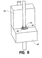
- FIG. 8 shows a mold having a strand cavity 30 shaped to deform the strands into radially fanned strands 44 (The cable is shown sectioned to aid visualization). A separator 26 is also used.
- FIG. 9 shows injector 46. Needle 48 extends from its lower surface. Injection orifice 50 passes through needle 48 (The orifice can assume a variety of shapes). The lower surface also opens into a pair of vents 52.
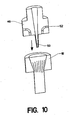
- FIG. 10 shows injector 46 in a section view. Injection orifice 50 is connected to a supply of liquid potting compound (not shown). Vents 52 can be vented to the surrounding air.
- a mold is placed around the dry exposed strands on the end of a cable.
- an anchor 18 is actually used as the mold (Split molds such as shown previously could also be used).
- the anchor has an expanding internal passage which serves as a strand cavity. It also has an open end. Injector 46 is moved toward the exposed strands as indicated.
- FIG. 11 shows injector 46 mated to anchor 18.
- the lower surface of injector 46 is actually pressed against the upper surface of anchor 18 to form a sealing surface.
- Needle 48 protrudes down into the exposed strands.
- Liquid potting compound is then infused through injection orifice 50. It flows out through the strands toward the two vents 52, thereby completely infusing the strands within the anchor's internal passage. Once the infusion is completed, injector 46 is withdrawn. The liquid potting compound then hardens to complete the termination.
- injector 46 can take many forms, including breaking the injector into two or more pieces (like a mold). Needle 48 is optional. The injection could be accomplished via forcing the liquid potting compound through a simple hole. Such an alternate embodiment is shown in FIG. 9B . Likewise, the seal between injector 46 and anchor 18 can be achieved using many methods, including an O-ring or interlocking threads. With the anchor itself forming the mold, it may be advisable to add infeed runners or vents to the anchor. These features could take many shapes.
- a split mold can be used in the place of anchor 18.
- the anchor would be added after the infusion process is complete.
Landscapes
- Engineering & Computer Science (AREA)
- General Engineering & Computer Science (AREA)
- Mechanical Engineering (AREA)
- Casting Or Compression Moulding Of Plastics Or The Like (AREA)
- Processing Of Terminals (AREA)
- Coating Apparatus (AREA)
- Application Of Or Painting With Fluid Materials (AREA)
- Piles And Underground Anchors (AREA)
Abstract
Description
- This invention relates to the field of cables and ropes. More specifically, the invention comprises a process for infusing liquid potting compound into the strands of a rope or cable prior to affixing an anchor or for other uses.
- Devices for mounting a termination on the end of a rope or cable are disclosed in detail in
U.S. Application Serial No. 60/404973 (Publication No.US2004/0083607 ) and also inNL 7212077 - It is often useful to affix a piece of hardware to the end of a cable. Examples of hardware would be threaded fasteners, hooks, and eyes. Such hardware will be generically referred to as an "anchor." Anchors typically have an expanding internal passage or some type of interlocking features, such as ridges. The strands proximate the end of a cable are wetted with liquid potting compound. The wetted strands are then placed within the internal passage of the anchor. The potting compound then hardens to form a solid, thereby locking a length of strands into the anchor. The anchor, along with the contained strands and solid potting compound will be referred to as a "termination."
- Those skilled in the art will know that the term "potting compound" generally refers to any liquid which can be transformed into a solid (such as by air-drying, cooling, reacting with a catalyst, etc.). Examples include thermoplastics, molten metals, thermoset plastics, and reactive compounds (such as two-part epoxies).
- Two methods of infusing liquid potting compound into the strands of a cable are in common use. These are: (1) Pulling an anchor into its final position around the exposed strands and pouring the liquid potting compound into an open end of the anchor; or (2) Infusing the exposed strands with liquid potting compound, then pulling the anchor into its final position (The infusion is typically accomplished via painting on the liquid potting compound or dipping the exposed strands into a vat of liquid potting compound).
- Under either approach, the potting compound may fail to fully infuse the strands. Moreover, both approaches must generally be performed manually, resulting in drastic variations from termination to termination.
- According to the present invention there is provided a method for infusing a region of strands in a cable with liquid potting compound, comprising:
- a. exposing said region of strands in said cable;
- b. providing a mold including
- i. a strand cavity;
- ii. an infeed runner for carrying said liquid potting compound, wherein said infeed runner leads into said strand cavity;
- c. placing said region of strands within said strand cavity within said mold; and
- d. injecting said liquid potting compound into said strand cavity through said infeed runner, so that said liquid potting compound infuses throughout said region of strands.
- A second venting passage is preferably employed, so that the liquid potting compound flows through the mold without trapping any air pockets. After infusion and before the liquid potting compound hardens, the mold is opened.
- Preferred embodiments of the invention will now be described by way of example with reference to the accompanying drawings in which:-
-
FIG. 1 is an isomeric view, showing various cable strand configurations. -
FIG. 2 is an isometric view, showing the operation of a mold. -
FIG. 3 is an isometric view, showing internal passages within the mold. -
FIG. 4 is an isometric section view, showing the mold base. -
FIG. 5 is an isometric view, showing the installation of an anchor. -
FIG. 6 is an isometric view, showing the installation of an anchor. -
FIG. 7 is an isometric view, showing the mold on an assembly line. -
FIG. 8 is an isometric view, showing a cable clamped within a mold. -
FIG. 9 is an isometric view, showing an injector. -
FIG. 9B is an isometric view, showing an alternate injector. -
FIG. 10 is an isometric section view, showing the operation of an injector. -
FIG. 11 is an isometric section view, showing the operation of an injector. -
FIG. 1 shows fourcables 10 with exposed strands in varying configurations. The far left example showscore strands 12 exposed and ready for potting in an undisturbed state. Proceeding to the right, the next example shows the exposed strands being compressed to form fanned strands 14. The next example shows the exposed strands being splayed to formconical strands 16. The far right example shows the strands being splayed apart further to form radially fannedstrands 44. All these examples, as well as others, may be employed prior to infusing the exposed strands with liquid potting resin. -
FIG. 2 shows one embodiment of the present invention.Anchor 18 is placed oncable 10 and pulled away from the exposed end strands to the position shown.Cable 10 is then positioned between the upper mold portions 20 (In the example shown, two mold portions are used. The upper portion of the mold can also be split into three or more portions). Eachupper mold portion 20 preferably includes acable cavity 28 and astrand cavity 30.Mold base 22 lies beneathcable 10. The twoupper mold portions 20 clamp securely together, as indicated by the arrows. This action results incable 10 being held tightly within the internal passages in the two upper mold portions. - Mold
base 22 then moves upward to seal off the bottom ofcable 10. Those skilled in the art will realize that the type of mold shown is but one among many. The mold could split in other ways, move together in different ways, etc. - Once the mold closes,
cable 10 is held securely within the internal passages.FIG. 3 is a sectional view of one of the twoupper mold portions 20. The reader will observe thatinfeed runner 32 connectsliquid coupling 34 withstrand cavity 30. When clamped in place, preferably pressurized liquid potting compound is forced throughinfeed runner 32 where it emerges in and around the exposed strands ofcable 10.Cable cavity 28 is clamped securely around the rest ofcable 10, thereby preventing the liquid potting compound from diffusing upward beyond the exposed end strands. As an alternative, a fairly loose fit can be provided aroundcable 10 so that entrapped air can ventpast cable 10. The second upper molding portion can be equipped with a corresponding infeed runner. Additional infeed runners could also be provided in the mold base.
An infeed runner could be placed at virtually any location and in any orientation withinstrand cavity 30. -
FIG. 4 is an isometric section view ofmold base 22. Its upper surface opens into strand cavity 24 (A flat upper surface having no recess can also be used). A conically shapedseparator 26 may be provided in the middle in order to splay the exposed strands of the cable whenmold base 22 is moved up into position.Mold base 22 is preferably equipped with one or more liquid vents 36. These connect to ventcoupling 38. In operation, the mold parts are clamped together to form theenclosed strand cavity 30. Liquid potting compound is then forced under pressure into the mold throughinfeed runners 32.Liquid vents 36 allow air within the mold cavity to escape. Eventually, liquid potting compound completely fills the cavity and flows out through liquid vents 36. A vacuum may be applied to ventcoupling 38 in order to promote faster flow or more complete liquid potting compound infusion. - As an alternative, the infeed runners and liquid vents can be reversed so that the liquid potting compound flows from the bottom to the top. Vacuum and pressure can also be used interchangeably to create the desired flow. Although the runners and vents have been shown as circular, those skilled in the art will know that they could also be made with an oval cross section, a square cross section, or any other desired shape.
-
FIG. 5 showscable 10 after its end strands have been infused with liquid potting compound within the mold. The end strands are now denoted as infusedstrands 40.Anchor 18 is then moved down in the direction shown until it encloses the infused end strands (or otherwise mechanically interlocks).Anchor 18 is shown in its final position inFIG. 6 . It remains in this position while the liquid potting compound hardens into a solid, thereby forming a completed termination. As an alternative,anchor 18 can be slid into position from the opposite end of the cable after the liquid potting compound is applied. -
FIG. 7 shows the application of the devices and processes disclosed to an assembly line. A series of cables 10 - withanchors 18 in an appropriate position, are sequentially fed along the line in the direction indicated by the arrow. Themiddle cable 10 is set to be clamped within the mold components. Its exposed end strands will then be infused with liquid potting compound. Thecable 10 immediately to the right of themiddle cable 10 has just exited the mold. Its end strands have been infused with liquid potting compound. They are thus denoted as infusedstrands 40. - As
cable 10 moves further down the line, anchor fork 42 (or other suitable devices, whether automatic or manual), may be employed to pullanchor 18 into the appropriate position before the liquid potting compound hardens. Similar devices can be employed to retain the anchors in the appropriate positions throughout the process. - The same process can be applied where a mold is substituted for
anchor 18. In other words, a mold can be pulled in place over the strands while they are allowed to set. This mold can then be removed and the strands placed in a separate anchor. - Those skilled in the art will realize that the internal cavities within the mold components, as well as the infeed runners and vents, can be made in virtually any shape. Multicavity molds can also be used to increase the feed rates. Returning to
FIG. 1 , the reader will appreciate that the mold can be configured to clamp the fibers in any one of the four configurations shown (as well as others). As an example,FIG. 8 shows a mold having astrand cavity 30 shaped to deform the strands into radially fanned strands 44 (The cable is shown sectioned to aid visualization). Aseparator 26 is also used. - The injection process can even be modified to infuse the liquid potting compound from the center of the exposed strands outward.
FIG. 9 showsinjector 46.Needle 48 extends from its lower surface.Injection orifice 50 passes through needle 48 (The orifice can assume a variety of shapes). The lower surface also opens into a pair ofvents 52.FIG. 10 showsinjector 46 in a section view.Injection orifice 50 is connected to a supply of liquid potting compound (not shown).Vents 52 can be vented to the surrounding air. In operation, a mold is placed around the dry exposed strands on the end of a cable. For the example shown, ananchor 18 is actually used as the mold (Split molds such as shown previously could also be used). The anchor has an expanding internal passage which serves as a strand cavity. It also has an open end.Injector 46 is moved toward the exposed strands as indicated. -
FIG. 11 showsinjector 46 mated to anchor 18. The lower surface ofinjector 46 is actually pressed against the upper surface ofanchor 18 to form a sealing surface.Needle 48 protrudes down into the exposed strands. Liquid potting compound is then infused throughinjection orifice 50. It flows out through the strands toward the twovents 52, thereby completely infusing the strands within the anchor's internal passage. Once the infusion is completed,injector 46 is withdrawn. The liquid potting compound then hardens to complete the termination. - Those skilled in the art will realize that
injector 46 can take many forms, including breaking the injector into two or more pieces (like a mold).Needle 48 is optional. The injection could be accomplished via forcing the liquid potting compound through a simple hole. Such an alternate embodiment is shown inFIG. 9B . Likewise, the seal betweeninjector 46 andanchor 18 can be achieved using many methods, including an O-ring or interlocking threads. With the anchor itself forming the mold, it may be advisable to add infeed runners or vents to the anchor. These features could take many shapes. - As stated previously, a split mold can be used in the place of
anchor 18. In such a case, the anchor would be added after the infusion process is complete. - Throughout the preceding disclosure, terms referring to the orientation of the parts have been used ("upper", "lower", etc.). Those skilled in the art will realize that the orientation of the components has no significant impact on the operation of the devices. These terms referred only to the orientations shown in the views, and should not be taken as limiting the scope of the invention.
- Although the preceding description contains significant detail, it should not be construed as limiting the scope of the invention but rather as providing illustrations of the preferred embodiments of the invention, as defined in the claims.
Claims (6)
- A method for attaching an anchor (18) having an internal passage and an open end to a region of strands (40) on an end of a cable (10) , comprising:a. exposing said region of strands (40) in said cable (10);b. placing said region of strands (40) within said internal passage of said anchor (18);
the method being characterized by:-c. providing an injector (46), includingi. a sealing surface;ii. a needle (48), extending from said sealing surface, having a first end proximate said sealing surface and a second end distal to said sealing surface;iii. an injection orifice (50) proximate said second end of said needle (48);d. clamping said injector (46) against said open end of said anchor (18) so that said needle (48) protrudes into said region of strands (40) and said sealing surface seals said open end of said anchor (18);e. providing a potting compound which transitions from a liquid state to a solid state over time;f. injecting said potting compound, in said liquid state, under pressure into said strand cavity through said injection orifice (50), so that said liquid potting compound infuses throughout said region of strands (40);g. withdrawing said needle (48) while said potting compound is still in said liquid state; andh. allowing said liquid potting compound to harden into a solid, thereby locking said region of strands (40) within said anchor (18). - A method as recited in claim 1, wherein said step of exposing said region of strands (40) comprises splaying said region of strands (40) into a fan.
- A method as recited in claim 1, wherein said step of exposing said region of strands (40) comprises splaying said region of strands (40) into a cone.
- A method as recited in claim 1, wherein said step of exposing said region of strands (40) comprises splaying said region of strands (40) into a radial fan.
- A method as recited in claim 1, comprising the additional step of providing said injector (46) with a vent (52).
- A method as recited in claim 5, comprising the additional step of applying a vacuum to said vent (52).
Priority Applications (4)
| Application Number | Priority Date | Filing Date | Title |
|---|---|---|---|
| EP04254762A EP1624224B1 (en) | 2004-08-06 | 2004-08-06 | A method for infusing a region of strands in a cable with liquid potting compound |
| AT04254762T ATE395529T1 (en) | 2004-08-06 | 2004-08-06 | METHOD FOR CASTING ROPE STRANDS WITH LIQUID CASTING COMPOUND |
| DE602004013764T DE602004013764D1 (en) | 2004-08-06 | 2004-08-06 | Method for casting ropes with liquid potting compound |
| PT04254762T PT1624224E (en) | 2004-08-06 | 2004-08-06 | A method for infusing a region of strands in a cable with liquid potting compound |
Applications Claiming Priority (1)
| Application Number | Priority Date | Filing Date | Title |
|---|---|---|---|
| EP04254762A EP1624224B1 (en) | 2004-08-06 | 2004-08-06 | A method for infusing a region of strands in a cable with liquid potting compound |
Publications (2)
| Publication Number | Publication Date |
|---|---|
| EP1624224A1 EP1624224A1 (en) | 2006-02-08 |
| EP1624224B1 true EP1624224B1 (en) | 2008-05-14 |
Family
ID=34930546
Family Applications (1)
| Application Number | Title | Priority Date | Filing Date |
|---|---|---|---|
| EP04254762A Expired - Lifetime EP1624224B1 (en) | 2004-08-06 | 2004-08-06 | A method for infusing a region of strands in a cable with liquid potting compound |
Country Status (4)
| Country | Link |
|---|---|
| EP (1) | EP1624224B1 (en) |
| AT (1) | ATE395529T1 (en) |
| DE (1) | DE602004013764D1 (en) |
| PT (1) | PT1624224E (en) |
Family Cites Families (3)
| Publication number | Priority date | Publication date | Assignee | Title |
|---|---|---|---|---|
| DE200897C (en) * | ||||
| NL7212077A (en) * | 1972-09-05 | 1974-03-07 | Thickening a rope end - held by a former and injected by needle with syn-thetic resin | |
| CN1296155C (en) * | 2001-07-16 | 2007-01-24 | 空运物流公司 | Composite tensioning members and method for manufacturing same |
-
2004
- 2004-08-06 PT PT04254762T patent/PT1624224E/en unknown
- 2004-08-06 DE DE602004013764T patent/DE602004013764D1/en not_active Expired - Fee Related
- 2004-08-06 AT AT04254762T patent/ATE395529T1/en not_active IP Right Cessation
- 2004-08-06 EP EP04254762A patent/EP1624224B1/en not_active Expired - Lifetime
Also Published As
| Publication number | Publication date |
|---|---|
| PT1624224E (en) | 2008-08-22 |
| DE602004013764D1 (en) | 2008-06-26 |
| ATE395529T1 (en) | 2008-05-15 |
| EP1624224A1 (en) | 2006-02-08 |
Similar Documents
| Publication | Publication Date | Title |
|---|---|---|
| US8048357B2 (en) | Resin infusion potting | |
| US12123476B2 (en) | Inverted injection method of affixing a termination to a tensile member | |
| US6957485B2 (en) | Moldable cable termination system | |
| US20050082716A1 (en) | Resin infusion potting | |
| US20040083607A1 (en) | Cable manufacturing method | |
| US7076853B2 (en) | Method for infusing potting compound into strands of a cable | |
| EP1624224A1 (en) | A method for infusing a region of strands in a cable with liquid potting compound | |
| CN113453864B (en) | Injection molding of components onto cables | |
| US4483904A (en) | Connecting fibre reinforced pultrusions | |
| DE10101271A1 (en) | Resin transfer molded fiber reinforced plastic component for connection to a support, has an insert with surface profiles to locate it in the molding tool and retain it in the component | |
| US20060096089A1 (en) | Method for standardizing hardware for synthetic cables | |
| JPH05318608A (en) | Pultrusion method and pultrusion mold | |
| DE102009048877A1 (en) | Cable entry in connector housings | |
| EP3430688B1 (en) | Waterproof wall mount for connector | |
| EP1101047B1 (en) | Cable end connection | |
| US11378159B2 (en) | Wicking termination system | |
| CN113665127A (en) | Connecting elements, composite parts, and methods of making parts from composite materials | |
| KR20170024399A (en) | grommet molding device | |
| JPH02301412A (en) | Molding method for fiber reinforced resin molded product | |
| DE102013220990A1 (en) | Blow hose for internal pressure injection molding | |
| Dave et al. | Method and Apparatus for Making Composite Materials | |
| DE4034393C2 (en) | Method of making a golf club | |
| DE29924570U1 (en) | Cable end connection which is protected against corrosion |
Legal Events
| Date | Code | Title | Description |
|---|---|---|---|
| PUAI | Public reference made under article 153(3) epc to a published international application that has entered the european phase |
Free format text: ORIGINAL CODE: 0009012 |
|
| AK | Designated contracting states |
Kind code of ref document: A1 Designated state(s): AT BE BG CH CY CZ DE DK EE ES FI FR GB GR HU IE IT LI LU MC NL PL PT RO SE SI SK TR |
|
| AX | Request for extension of the european patent |
Extension state: AL HR LT LV MK |
|
| 17P | Request for examination filed |
Effective date: 20060808 |
|
| AKX | Designation fees paid |
Designated state(s): AT BE BG CH CY CZ DE DK EE ES FI FR GB GR HU IE IT LI LU MC NL PL PT RO SE SI SK TR |
|
| 17Q | First examination report despatched |
Effective date: 20060919 |
|
| GRAP | Despatch of communication of intention to grant a patent |
Free format text: ORIGINAL CODE: EPIDOSNIGR1 |
|
| GRAS | Grant fee paid |
Free format text: ORIGINAL CODE: EPIDOSNIGR3 |
|
| GRAA | (expected) grant |
Free format text: ORIGINAL CODE: 0009210 |
|
| AK | Designated contracting states |
Kind code of ref document: B1 Designated state(s): AT BE BG CH CY CZ DE DK EE ES FI FR GB GR HU IE IT LI LU MC NL PL PT RO SE SI SK TR |
|
| REG | Reference to a national code |
Ref country code: GB Ref legal event code: FG4D |
|
| REG | Reference to a national code |
Ref country code: CH Ref legal event code: EP |
|
| REG | Reference to a national code |
Ref country code: IE Ref legal event code: FG4D Free format text: LANGUAGE OF EP DOCUMENT: FRENCH |
|
| REF | Corresponds to: |
Ref document number: 602004013764 Country of ref document: DE Date of ref document: 20080626 Kind code of ref document: P |
|
| REG | Reference to a national code |
Ref country code: PT Ref legal event code: SC4A Free format text: AVAILABILITY OF NATIONAL TRANSLATION Effective date: 20080812 |
|
| PG25 | Lapsed in a contracting state [announced via postgrant information from national office to epo] |
Ref country code: SI Free format text: LAPSE BECAUSE OF FAILURE TO SUBMIT A TRANSLATION OF THE DESCRIPTION OR TO PAY THE FEE WITHIN THE PRESCRIBED TIME-LIMIT Effective date: 20080514 |
|
| PG25 | Lapsed in a contracting state [announced via postgrant information from national office to epo] |
Ref country code: FI Free format text: LAPSE BECAUSE OF FAILURE TO SUBMIT A TRANSLATION OF THE DESCRIPTION OR TO PAY THE FEE WITHIN THE PRESCRIBED TIME-LIMIT Effective date: 20080514 Ref country code: ES Free format text: LAPSE BECAUSE OF FAILURE TO SUBMIT A TRANSLATION OF THE DESCRIPTION OR TO PAY THE FEE WITHIN THE PRESCRIBED TIME-LIMIT Effective date: 20080825 |
|
| PG25 | Lapsed in a contracting state [announced via postgrant information from national office to epo] |
Ref country code: PL Free format text: LAPSE BECAUSE OF FAILURE TO SUBMIT A TRANSLATION OF THE DESCRIPTION OR TO PAY THE FEE WITHIN THE PRESCRIBED TIME-LIMIT Effective date: 20080514 Ref country code: AT Free format text: LAPSE BECAUSE OF FAILURE TO SUBMIT A TRANSLATION OF THE DESCRIPTION OR TO PAY THE FEE WITHIN THE PRESCRIBED TIME-LIMIT Effective date: 20080514 |
|
| PG25 | Lapsed in a contracting state [announced via postgrant information from national office to epo] |
Ref country code: SE Free format text: LAPSE BECAUSE OF FAILURE TO SUBMIT A TRANSLATION OF THE DESCRIPTION OR TO PAY THE FEE WITHIN THE PRESCRIBED TIME-LIMIT Effective date: 20080814 Ref country code: CZ Free format text: LAPSE BECAUSE OF FAILURE TO SUBMIT A TRANSLATION OF THE DESCRIPTION OR TO PAY THE FEE WITHIN THE PRESCRIBED TIME-LIMIT Effective date: 20080514 Ref country code: DK Free format text: LAPSE BECAUSE OF FAILURE TO SUBMIT A TRANSLATION OF THE DESCRIPTION OR TO PAY THE FEE WITHIN THE PRESCRIBED TIME-LIMIT Effective date: 20080514 |
|
| PG25 | Lapsed in a contracting state [announced via postgrant information from national office to epo] |
Ref country code: SK Free format text: LAPSE BECAUSE OF FAILURE TO SUBMIT A TRANSLATION OF THE DESCRIPTION OR TO PAY THE FEE WITHIN THE PRESCRIBED TIME-LIMIT Effective date: 20080514 Ref country code: RO Free format text: LAPSE BECAUSE OF FAILURE TO SUBMIT A TRANSLATION OF THE DESCRIPTION OR TO PAY THE FEE WITHIN THE PRESCRIBED TIME-LIMIT Effective date: 20080514 |
|
| PLBE | No opposition filed within time limit |
Free format text: ORIGINAL CODE: 0009261 |
|
| STAA | Information on the status of an ep patent application or granted ep patent |
Free format text: STATUS: NO OPPOSITION FILED WITHIN TIME LIMIT |
|
| PG25 | Lapsed in a contracting state [announced via postgrant information from national office to epo] |
Ref country code: MC Free format text: LAPSE BECAUSE OF NON-PAYMENT OF DUE FEES Effective date: 20080831 |
|
| REG | Reference to a national code |
Ref country code: CH Ref legal event code: PL |
|
| 26N | No opposition filed |
Effective date: 20090217 |
|
| PG25 | Lapsed in a contracting state [announced via postgrant information from national office to epo] |
Ref country code: EE Free format text: LAPSE BECAUSE OF FAILURE TO SUBMIT A TRANSLATION OF THE DESCRIPTION OR TO PAY THE FEE WITHIN THE PRESCRIBED TIME-LIMIT Effective date: 20080514 Ref country code: BG Free format text: LAPSE BECAUSE OF FAILURE TO SUBMIT A TRANSLATION OF THE DESCRIPTION OR TO PAY THE FEE WITHIN THE PRESCRIBED TIME-LIMIT Effective date: 20080814 |
|
| PG25 | Lapsed in a contracting state [announced via postgrant information from national office to epo] |
Ref country code: CH Free format text: LAPSE BECAUSE OF NON-PAYMENT OF DUE FEES Effective date: 20080831 Ref country code: LI Free format text: LAPSE BECAUSE OF NON-PAYMENT OF DUE FEES Effective date: 20080831 |
|
| PG25 | Lapsed in a contracting state [announced via postgrant information from national office to epo] |
Ref country code: IE Free format text: LAPSE BECAUSE OF NON-PAYMENT OF DUE FEES Effective date: 20080806 |
|
| PG25 | Lapsed in a contracting state [announced via postgrant information from national office to epo] |
Ref country code: DE Free format text: LAPSE BECAUSE OF NON-PAYMENT OF DUE FEES Effective date: 20090303 Ref country code: IT Free format text: LAPSE BECAUSE OF FAILURE TO SUBMIT A TRANSLATION OF THE DESCRIPTION OR TO PAY THE FEE WITHIN THE PRESCRIBED TIME-LIMIT Effective date: 20080514 |
|
| PG25 | Lapsed in a contracting state [announced via postgrant information from national office to epo] |
Ref country code: LU Free format text: LAPSE BECAUSE OF NON-PAYMENT OF DUE FEES Effective date: 20080806 Ref country code: CY Free format text: LAPSE BECAUSE OF FAILURE TO SUBMIT A TRANSLATION OF THE DESCRIPTION OR TO PAY THE FEE WITHIN THE PRESCRIBED TIME-LIMIT Effective date: 20080514 Ref country code: HU Free format text: LAPSE BECAUSE OF FAILURE TO SUBMIT A TRANSLATION OF THE DESCRIPTION OR TO PAY THE FEE WITHIN THE PRESCRIBED TIME-LIMIT Effective date: 20081115 |
|
| PG25 | Lapsed in a contracting state [announced via postgrant information from national office to epo] |
Ref country code: TR Free format text: LAPSE BECAUSE OF FAILURE TO SUBMIT A TRANSLATION OF THE DESCRIPTION OR TO PAY THE FEE WITHIN THE PRESCRIBED TIME-LIMIT Effective date: 20080514 |
|
| PG25 | Lapsed in a contracting state [announced via postgrant information from national office to epo] |
Ref country code: GR Free format text: LAPSE BECAUSE OF FAILURE TO SUBMIT A TRANSLATION OF THE DESCRIPTION OR TO PAY THE FEE WITHIN THE PRESCRIBED TIME-LIMIT Effective date: 20080815 |
|
| REG | Reference to a national code |
Ref country code: FR Ref legal event code: PLFP Year of fee payment: 13 |
|
| REG | Reference to a national code |
Ref country code: FR Ref legal event code: PLFP Year of fee payment: 14 |
|
| REG | Reference to a national code |
Ref country code: FR Ref legal event code: PLFP Year of fee payment: 15 |
|
| PGFP | Annual fee paid to national office [announced via postgrant information from national office to epo] |
Ref country code: NL Payment date: 20200225 Year of fee payment: 16 |
|
| PGFP | Annual fee paid to national office [announced via postgrant information from national office to epo] |
Ref country code: FR Payment date: 20200206 Year of fee payment: 16 |
|
| REG | Reference to a national code |
Ref country code: NL Ref legal event code: MM Effective date: 20200901 |
|
| PG25 | Lapsed in a contracting state [announced via postgrant information from national office to epo] |
Ref country code: FR Free format text: LAPSE BECAUSE OF NON-PAYMENT OF DUE FEES Effective date: 20200831 |
|
| PG25 | Lapsed in a contracting state [announced via postgrant information from national office to epo] |
Ref country code: NL Free format text: LAPSE BECAUSE OF NON-PAYMENT OF DUE FEES Effective date: 20200901 |
|
| PGFP | Annual fee paid to national office [announced via postgrant information from national office to epo] |
Ref country code: BE Payment date: 20210827 Year of fee payment: 18 Ref country code: GB Payment date: 20210820 Year of fee payment: 18 |
|
| PGFP | Annual fee paid to national office [announced via postgrant information from national office to epo] |
Ref country code: PT Payment date: 20210826 Year of fee payment: 18 |
|
| GBPC | Gb: european patent ceased through non-payment of renewal fee |
Effective date: 20220806 |
|
| PG25 | Lapsed in a contracting state [announced via postgrant information from national office to epo] |
Ref country code: PT Free format text: LAPSE BECAUSE OF NON-PAYMENT OF DUE FEES Effective date: 20230206 |
|
| REG | Reference to a national code |
Ref country code: BE Ref legal event code: MM Effective date: 20220831 |
|
| PG25 | Lapsed in a contracting state [announced via postgrant information from national office to epo] |
Ref country code: BE Free format text: LAPSE BECAUSE OF NON-PAYMENT OF DUE FEES Effective date: 20220831 |
|
| PG25 | Lapsed in a contracting state [announced via postgrant information from national office to epo] |
Ref country code: GB Free format text: LAPSE BECAUSE OF NON-PAYMENT OF DUE FEES Effective date: 20220806 |