EP1624188A2 - Plunger pump and method of controlling discharge of the pump - Google Patents
Plunger pump and method of controlling discharge of the pump Download PDFInfo
- Publication number
- EP1624188A2 EP1624188A2 EP05016783A EP05016783A EP1624188A2 EP 1624188 A2 EP1624188 A2 EP 1624188A2 EP 05016783 A EP05016783 A EP 05016783A EP 05016783 A EP05016783 A EP 05016783A EP 1624188 A2 EP1624188 A2 EP 1624188A2
- Authority
- EP
- European Patent Office
- Prior art keywords
- plunger
- fluid
- outlet
- discharge
- pump chamber
- Prior art date
- Legal status (The legal status is an assumption and is not a legal conclusion. Google has not performed a legal analysis and makes no representation as to the accuracy of the status listed.)
- Withdrawn
Links
Images




Classifications
-
- F—MECHANICAL ENGINEERING; LIGHTING; HEATING; WEAPONS; BLASTING
- F04—POSITIVE - DISPLACEMENT MACHINES FOR LIQUIDS; PUMPS FOR LIQUIDS OR ELASTIC FLUIDS
- F04B—POSITIVE-DISPLACEMENT MACHINES FOR LIQUIDS; PUMPS
- F04B23/00—Pumping installations or systems
- F04B23/04—Combinations of two or more pumps
- F04B23/06—Combinations of two or more pumps the pumps being all of reciprocating positive-displacement type
-
- F—MECHANICAL ENGINEERING; LIGHTING; HEATING; WEAPONS; BLASTING
- F04—POSITIVE - DISPLACEMENT MACHINES FOR LIQUIDS; PUMPS FOR LIQUIDS OR ELASTIC FLUIDS
- F04B—POSITIVE-DISPLACEMENT MACHINES FOR LIQUIDS; PUMPS
- F04B17/00—Pumps characterised by combination with, or adaptation to, specific driving engines or motors
- F04B17/03—Pumps characterised by combination with, or adaptation to, specific driving engines or motors driven by electric motors
- F04B17/04—Pumps characterised by combination with, or adaptation to, specific driving engines or motors driven by electric motors using solenoids
- F04B17/042—Pumps characterised by combination with, or adaptation to, specific driving engines or motors driven by electric motors using solenoids the solenoid motor being separated from the fluid flow
-
- F—MECHANICAL ENGINEERING; LIGHTING; HEATING; WEAPONS; BLASTING
- F04—POSITIVE - DISPLACEMENT MACHINES FOR LIQUIDS; PUMPS FOR LIQUIDS OR ELASTIC FLUIDS
- F04B—POSITIVE-DISPLACEMENT MACHINES FOR LIQUIDS; PUMPS
- F04B7/00—Piston machines or pumps characterised by having positively-driven valving
- F04B7/04—Piston machines or pumps characterised by having positively-driven valving in which the valving is performed by pistons and cylinders coacting to open and close intake or outlet ports
Definitions
- the present invention relates to a plunger pump that sucks a constant amount of fluid from a fluid source to discharge and to a method of controlling discharge of the pump.
- Patent Documents 1 to 3 each disclose a plunger type electromagnetic pump that reciprocates a plunger with electromagnetic activation force generated by applying current to an electromagnetic coil.
- FIG.8 illustrates a plunger type electromagnetic pump of the same type as that of the electromagnetic pump disclosed in Patent Documents 1 to 3.
- a plunger pump 100 has a cylinder 102, and a plunger 104 that is inserted in the cylinder 102 to be slidable. More specifically, the cylinder 102 has a suction side S and discharge side D, and the plunger 104 is inserted slidably in a continuous hole 106 formed on the suction side S of the cylinder 102.
- the plunger 104 is provided with an inlet 108 to suck a fluid such as lubricating oil from a fluid source such as a reservoir tank not shown, and the cylinder 102 is provided at its discharge side D with an outlet 110 that discharges the fluid sucked through the inlet 108 and that is communicated with the continuous hole 106.
- a fluid source such as a reservoir tank not shown
- the plunger 104 is slid inside the continuous hole 106 by electromagnetic activation force generated by applying current to an electromagnetic coil of a solenoid not shown, and a pump chamber 120 to suck and discharge the fluid is formed between the plunger 104 and outlet 110.
- a fluid suction passage 112 that connects the pump chamber 120 and inlet108 is formed in the plunger 104 along the axis of the plunger 104.
- an opening 112a of the fluid suction passage 112 opened to the pump chamber 120 is opened and closed by a suction valve 125 with sliding of the plunger 104.
- the suction valve 125 is provided inside the pump chamber 120, and comprised of a sphere-shaped valve body 125a, and a spring 125b that is inserted between the valve body 125a and outlet 110 and that supports the valve body 125a for the cylinder 102.
- the outlet 110 is provided with a discharge valve 130 that constitutes a one-way valve.
- the discharge valve 130 is comprised of a sphere-shaped valve body 130a and compression spring 130b, usually presses the valve body 130a against a base 110a of the outlet 110 by force of the compression spring 130b to close the outlet 110, and only when a pressure exceeding the force of the compression spring 130b is generated inside the pump chamber 120, opens the outlet 110.
- the valve body 125a of the suction valve 125 gets away from the opening 112a of the fluid suction passage 112, the opening 112a is opened, and the pump chamber 120 is communicated with the inlet 108. Accordingly, the fluid from the fluid source flows into the pump chamber 120.
- the valve body 130a gets away from the base 110a, the outlet 110 is opened, and the fluid in the pump chamber 120 is discharged from the outlet 110.
- the fluid discharged from the outlet 110 is guided to a lubricant target portion of an operating body such as an engine via a pipe-shaped connection cap 135 provided on the discharge side D of the cylinder 102.
- a series of problems as described above becomes more pronounced in multi-discharge type plunger pump comprised of a plurality of pump structures as shown in FIG.8 to discharge the fluid concurrently from a plurality of outlets.
- multi-discharge type plunger pump in the case of operating a plurality of plungers 104 at the same time by a common driving part and supplying different flow amounts from the outlets 110 at a constant discharge pitch with the same stroke set on all the plungers 104, as described previously, it is necessary to change an inner diameter of the continuous hole 106 for each of the plungers 104. In such a case, the assembly process becomes complicated, as well as the processing process becoming complicated, and further, the management process may increase.
- the time of applying the current to the electromagnetic coil (duration time of ON state) is fixed at a required minimum time, and the time of halting the application of current to the electromagnetic coil (duration time of OFF state) is adjusted to determine the frequency of driving the solenoid (see FIG.8(d)). Therefore, the current OFF time is inevitably long that is the fluid suction step time. However, when the current OFF time thus is long, one problem arises.
- a plunger pump has a cylinder having an inlet to suck a fluid from a fluid source and an outlet to discharge the sucked fluid, a continuous hole which is formed inside the cylinder and communicated with the outlet, a plunger which is inserted in the continuous hole to be slidable and forms a pump chamber to suck and discharge the fluid with the outlet where the pump chamber is formed between the plunger and the outlet, and a fluid suction passage which is formed in the cylinder or the plunger, to suck a fluid into the pump chamber, where an opening of the fluid suction passage opened to the pump chamber is opened and closed by the plunger sliding inside the continuous hole.
- the plunger pump of the first aspect since the opening of the fluid suction passage opened to the pump chamber is opened and closed by the plunger itself, in other words, the plunger is provided with the valve function (the plunger serves as a suction valve on the fluid suction side), the need is eliminated of providing a dedicated valve (for example, the suction valve 125 as shown in FIG.8) on the fluid suction side. Therefore, as compared with the conventional case, the number of components is decreased, the valve structure is simplified, the assembly is also simplified, and it is possible to miniaturize the entire plunger pump.
- any members are not present (such as, for example, the valve body 125a of the suction valve 125 as shown in FIG.8) that collide with the plunger with opening and closing of the opening of the fluid suction passage, it is possible to minimize the vibration and noise at the time the pump is operating, and to avoid wear of the valve structure and occurrence of failure in sealing inside the pump chamber due to the wear.
- the size and number of the fluid suction passages may be set optionally corresponding to a required discharge amount.
- a driving mechanism of the plunger any of conventionally known manners can be used such as a solenoid, motor, and cam driven by an engine.
- the fluid suction passage may be formed along the inner surface of the continuous and extend in parallel with the axis direction of the continuous hole, extend in the direction perpendicular to the axis direction of the continuous hole, or extend obliquely to the axis direction of the continuous hole.
- a plunger pump has a valve body that is provided to close the outlet and that opens the outlet only when receiving a predetermined pressure generated inside the pump chamber by the plunger sliding toward the outlet.
- a discharge amount of the fluid discharged from the outlet is determined by a top dead center of a stroke of the plunger and a position of the opening of the fluid suction passage.
- a discharge amount of the fluid discharged from the outlet is specified by a top dead center of a stoke of the plunger and a position of the opening of the fluid suction passage, it is possible to change a discharge amount (obtain a required discharge flow rate) with ease only by merely changing a position of the opening (accordingly, with simplified processing) without changing (an amount of) the stroke of the plunger and inner diameter of the continuous hole.
- a discharge amount (obtain a required discharge flow rate) with ease only by merely changing a position of the opening (accordingly, with simplified processing) without changing (an amount of) the stroke of the plunger and inner diameter of the continuous hole.
- top dead center is a position where the plunger is pushed in the continuous hole the deepest.
- the fluid suction passage is formed on the inner surface of the continuous hole along the axis direction thereof.
- the fluid suction passage is formed on the inner surface of the continuous hole along the axis direction thereof, the extending direction of the fluid suction passage is in accordance with the extending direction of the continuous hole, it is thereby possible to perform processing on the fluid suction passage in the same direction as in processing on the continuous hole, and the processing is thus easy.
- a driving part may be further provided to slide the plunger inside the continuous hole.
- the driving part may slide the plunger inside the continuous hole by electromagnetic activation force generated by applying current to the electromagnetic coil.
- various types of fluids are considered such as oils including lubricant oil and gasoline.
- the driving part in a plunger pump of a fifth aspect holds the plunger at the top dead center position of its stroke for a predetermined time.
- the plunger pump of the fifth aspect since the plunger is held at the top dead center position of its stroke for a predetermined time, it is possible to minimize the time the plunger is held at the bottom dead center position of its stroke (position having the risk of occurrence of the so-called blow-by phenomenon such that the fluid from a fluid source is sucked from the inlet and leaks from the outlet due to the valve body of the outlet being opened by a pressure difference between the pump suction side and discharge side) in one cycle of suction/discharge operation. In other words, it is possible to reduce to a minimum the time percentage of occurrence of the blow-by phenomenon by a pressure difference between the pump suction side and discharge side, and to secure a proper discharge amount.
- the aforementioned advantage is more effective as the driving frequency is lower.
- the adverse effect of minute leakage is more significant, and the blow-by and/or suppression time (OFF time) is longer, whereby the advantage is more useful in discharging a small amount of fluid (a set discharge amount is small in one cycle).
- the driving part in a plunger pump of a sixth aspect holds the plunger at the top dead center position for a predetermined time by maintaining a voltage lower than an application voltage to the electromagnetic coil required to slide the plunger to the top dead center position.
- the voltage (power to maintain the discharge completion state) applied to the electromagnetic coil to keep the plunger at the top dead center position for a predetermined time is lower than the application voltage (power required to start discharging) required to slide the plunger to the top dead center position, power savings can be achieved (power consumption can be reduced).
- the thrust in the electromagnetic plunger part becomes the maximum in the discharge completion state, and therefore, the discharge completion state can be maintained sufficiently even when the operation voltage is decreased.
- a multi-discharge type plunger pump has a suction duct to suck a fluid from a fluid source, a plurality of cylinder parts each having an inlet communicated with the suction duct and an outlet to discharge the sucked fluid, continuous holes each of which is formed inside respective one of the cylinder parts and communicated with the outlet, plungers each of which is inserted in respective one of the continuous holes to be slidable and forms a pump chamber to suck and discharge the fluid with the outlet where the pump chamber is formed between each of the plungers and the outlet, and a plurality of fluid suction passages each of which is formed in respective one of the cylinder parts or plungers inserted in respective one of the continuous holes to suck a fluid into the pump chamber, where an opening of each of the fluid suction passages opened to the pump chamber is opened and closed by respective one of the plungers sliding in respective one of the continuous holes.
- the multi-discharge type plunger pump of the seventh aspect as well as obtaining the same effects and advantages in the first aspect, particularly, even in the case of operating a plurality of plungers at the same time by a common driving part and supplying different flow amounts from the outlets at a constant discharge pitch with the same stroke set on all the plungers, it is only required to change a position of the opening of each of the fluid suction passages without changing an inner diameter of the continuous hole for each of the plungers, and the processing is thus easy.
- the invention intends to provide a method of controlling discharge using the plunger pump with each of the above-mentioned structures.
- a desired compression rate is obtained, and it is possible to change a discharge amount with ease without changing a stroke of the plunger and/or the inner diameter of a sliding hole of the plunger, and to discharge a constant amount of fluid while preventing the fluid from leaking. Further, it is possible to extremely reduce both the noise and vibration in using the pump. Furthermore, the number of components is decreased, the assembly is simplified, and the size (particularly, longitudinal size) is reduced, thereby enabling miniaturization.
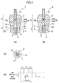
- FIG.1 shows a plunger pump 1 according to one embodiment of the invention.
- the plunger pump 1 of this embodiment is provided with a cylinder 2, and a cylindrical plunger 4 inserted in the cylinder 2 slidably.
- the cylinder 2 has a suction side S and discharge side D, and the plunger 4 is inserted slidably in a circular cross-section continuous hole 6 formed on the suction side S of the cylinder 2.
- the plunger 4 is provided with an inlet 8 to suck a fluid such as lubricant oil from a fluid source such as a reservoir tank not shown.
- the cylinder 2 is provided with an outlet 10 that discharges the fluid sucked through the inlet 8 and that is communicated with the continuous hole 6.
- the plunger 4 is slid inside the continuous hole 6 by the electromagnetic activation force generated by applying current to an electromagnetic coil of a solenoid (driving part) not shown, and forms a pump chamber 20 to suck and discharge the fluid between the outlet 10 and the plunger 4.
- the cylinder 2 is formed at least one fluid suction passage 12 that connects the pump chamber 20 and inlet 8.
- three fluid suction passages 12 are formed on the inner surface of the continuous hole 6 along the axis direction thereof at substantially same angle intervals in the circumferential direction of the continuous hole 6 (as the number of the passages, one or more number is applicable).
- each of the fluid suction passages 12 is obtained by cutting part of the inner surface of the continuous hole 6 toward the outside in the diameter direction, and thus formed between the inner surface of the cylinder 2 constituting the continuous hole 6 and the outer surface of the plunger 4, while its one end is terminated at a position spaced a predetermined distance away from the outlet 10 in the axis direction, and the other end is terminated at the end of the continuous hole 6 to form the inlet 8. Accordingly, an opening 19 of the fluid suction passage 12 opened to the pump chamber 20 is opened and closed by the plunger 4 itself sliding inside the continuous hole 6, and an opening degree of the opening 19 of the fluid suction passage 12 to the pump chamber 20 is varied with sliding of the plunger 4.
- the fluid suction passage 12 which connects the pump chamber 20 and the inlet 8 in order to suck a fluid into the pump chamber 20 is formed in the cylinder 2.
- the fluid suction passage 12 can be formed in the plunger 4 to have the same effect.
- the outlet 10 is provided with a discharge valve 30 that constitutes a one-way valve.
- the discharge valve 30 is comprised of a sphere-shaped valve body 30a and compression spring 30b, usually presses the valve body 30a against a base 10a of the outlet 10 by force of the compression spring 30b to close the outlet 10, and only when a pressure exceeding the force of the compression spring 30b is generated inside the pump chamber 20, opens the outlet 10.
- the plunger 4 is pushed in the continuous hole 6, and in a stage where the plunger 4 reaches the top dead center of its stroke, all the set discharge amount determined beforehand is discharged from the outlet 10.
- the set discharge amount in this case is specified by the top dead center of the stroke of the plunger 4 and a position of the opening 19 of the fluid suction passage 12.
- the plunger 4 when the plunger 4 reaches the top dead center of the stroke, the plunger 4 is held at the top dead center position for a predetermined time.
- the voltage to apply to the electromagnetic coil is maintained at a voltage value V 2 lower than a voltage value V 1 required to slide the plunger 4 to the top dead center position (see FIG.1(d)).
- the voltage applied to the electromagnetic coil is decreased from V 1 to V 2 , and kept at V 2 for a predetermined time.
- time T 2 to hold the plunger 4 at the top dead center position may be, for example, substantially half the time corresponding to one cycle of the suction/discharge operation, and is preferably set such that ON time T 1 plus the top dead center holing time T 2 exceeds OFF time T 3 . More specifically, the discharge completion time may be maintained for all the time except the time required for the suction and discharge steps.
- the pump chamber 20 that is a pump chamber is kept at a sealed state (because the opening 19 of the fluid suction passage 12 is closed by the plunger 4 and the inlet 8 and outlet 10 are not communicated with each other basically), and a clearance seal is provided between the plunger 4 and cylinder 2, whereby it is possible to suppress the so-called blow-by phenomenon where the fluid from a fluid source is sucked from the inlet 8 and leaks from the outlet 10 when the pressure on the discharge side D is lower than the pressure on the suction side S.
- the plunger 4 is provided with the valve function (the plunger 4 serves as a suction valve on the suction side S), the need is eliminated of providing a valve (for example, the suction valve 125 as shown in FIG.8) on the suction side S. Therefore, as compared with the conventional case, the number of components is decreased, the valve structure is simplified, the assembly is also simplified, and it is possible to miniaturize the entire plunger pump 1.
- any members are not present (such as, for example, the valve body 125a of the suction valve 125 as shown in FIG.8) that collide with the plunger 4 with opening and closing of the opening 19 of the fluid suction passage 12, it is possible to minimize the vibration and noise at the time the pump is operating, and to avoid wear of the valve structure and occurrence of failure in sealing inside the pump chamber 20 due to the wear.
- a discharge amount of fluid discharged from the outlet 10 is specified by the top dead center of the stroke of the plunger 4 and a position of the opening 19 of the fluid suction passage 12, it is possible to change a discharge amount (obtain a required discharge flow rate) with ease only by merely changing a position of the opening 19 (accordingly, with simplified processing) without changing the stroke of the plunger 4 and inner diameter of the continuous hole 6.
- a position of the opening 19 it is possible to vary a ratio of a suction stroke and discharge stroke to the entire stroke of the plunger 4.
- the extending direction of the fluid suction passage 12 is in accordance with the extending direction of the continuous hole 6, and it is thereby possible to perform processing on the fluid suction passage 12 in the same direction as in processing on the continuous hole 6.
- the plunger pump 1 of this embodiment since the plunger 4 is held at the top dead center position of its stroke for a predetermined time, it is possible to minimize the time the plunger 4 is held at the bottom dead center position of its stroke i.e. at the position having the risk of occurrence of the blow-by phenomenon in one cycle of suction/discharge operation. In other words, it is possible to reduce to a minimum the time percentage of occurrence of the blow-by phenomenon by a pressure difference between the suction side S and discharge side D, and to secure a proper discharge amount.
- the size and number of the fluid suction passages 12 can be set optionally corresponding to a required discharge amount. Further, the fluid suction passage 12 is formed on the inner surface of the continuous hole 6 along the axis direction thereof in this embodiment, but may be formed independently of the continuous hole 6 as shown in FIG.2.
- each of fluid suction passages 12' as shown in FIG.2 is comprised of a first passage 12a which is formed in the cylinder 2 independently of the continuous hole 6 and extends in parallel with the continuous hole 6, and a second passage 12b which extends in the direction perpendicular to the first passage 12a and serves as a horizontal hole to cause the first passage 12a to communicate with the pump chamber 20.
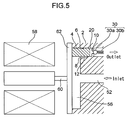
- FIGs.3 to 5 shows a multi-discharge type plunger pump 50 provided with a plurality of plunger pumps 1 as shown in FIG.1.
- the multi-discharge type plunger pump 50 is configured, for example, as a seven-discharge electromagnetic oil pump for two-cycle engine division refueling provided with seven plunger pumps 1 (accordingly, having seven outlets), and has a common suction duct 52 communicating with an oil source (fluid source) not shown.
- the cylinder (cylinder part) 2 of each of the plunger pumps 1 is formed integrally with a housing 54 of the multi-discharge type plunger pump 50.
- the structure and operation of each of the plunger pumps 1 is already explained in FIG.1, and therefore, the plunger pumps are assigned the same reference numerals as in FIG.1 to omit specific descriptions thereof.
- the suction duct 52 is communicated with a suction pump chamber 56 shared by the plunger pumps 1, and the inlet 8 of each of the plunger pumps 1 is opened to the suction pump chamber 56.
- the plunger 4 of each of the plunger pumps 1 is attached to a common driving plunger 62 that slides all the plungers at the same time in conjunction with one another, and reciprocates by the driving plunger 62 going back and forth due to the operation of a solenoid driving core 60 with the application of voltage to an electromagnetic coil 58 constituting a solenoid.
- a fluid sucked from one side of the multi-discharge type plunger pump 50 via the suction duct 52 enters the pump chamber 20 from the fluid suction passages 12 of each of the plunger pumps 1 while being inverted via the suction pump chamber 56, and is discharged from the one side where the suction duct 52 is situated in the opposite direction to the suction direction.
- At least some of seven outlets 10 are different from one another in discharge amount of the fluid to discharge. More specifically, the position of the opening 19 of the fluid suction passage 12 differs among the plunger pumps 1.
- the plunger pump 1 with the structure as shown in FIG.1, as in this embodiment, even in the case of operating a plurality of plungers 4 by a common driving part and supplying different flow amounts from the outlets 10 at a constant discharge pitch with the same stroke set on all the plungers 4, it is only required to change a position of the opening 19 of each of the fluid suction passages 12 without changing an inner diameter of the continuous hole 6 for each of the plungers 4, and the processing is thus easy.
- FIGs.6 and 7 show another embodiment of the multi-discharge type plunger pump, for example, used in an outboard motor.
- the multi-discharge type plunger pump 70 has the same basic structure as in the multi-discharge type plunger pump 50 as shown in FIGs.3 to 5, and is assigned the same reference numerals to omit specific descriptions thereof, but different from the multi-discharge type plunger pump 50 in the fluid suction/discharge direction that is linear.
- the fluid sucked from one side of the multi-discharge type plunger pump 70 via the suction duct 52 is flowed linearly via the suction pump chamber 56, enters the pump chamber 20 from the fluid suction passages 12 of each of the plunger pumps 1, and is discharged from the other side opposed to the side where the suction duct 52 is situated in the same direction as the suction direction.
- each plunger 4 is provided with a single outlet 10, but may be provided with a plurality of outlets 10. In this case, each of the outlets 10 is naturally provided with the discharge valve 30.
- the present invention relates to a plunger pump that sucks a constant amount of fluid from a fluid source to discharge and to a method of controlling discharge of the pump, and thus has the industrial applicability.
- the plunger pump is applicable to various plunger pumps that suck a variety of fluids to discharge.
Landscapes
- Engineering & Computer Science (AREA)
- Mechanical Engineering (AREA)
- General Engineering & Computer Science (AREA)
- Physics & Mathematics (AREA)
- Fluid Mechanics (AREA)
- Reciprocating Pumps (AREA)
- Electromagnetic Pumps, Or The Like (AREA)
Abstract
Description
- The present invention relates to a plunger pump that sucks a constant amount of fluid from a fluid source to discharge and to a method of controlling discharge of the pump.
- In plunger pumps that suck and discharge a fluid by reciprocating motion of a plunger, various manners have conventionally been proposed for the driving form of the plunger, arrangement form of valves and the like. For example,
Patent Documents 1 to 3 each disclose a plunger type electromagnetic pump that reciprocates a plunger with electromagnetic activation force generated by applying current to an electromagnetic coil. - FIG.8 illustrates a plunger type electromagnetic pump of the same type as that of the electromagnetic pump disclosed in
Patent Documents 1 to 3. As shown in the figure, aplunger pump 100 has acylinder 102, and aplunger 104 that is inserted in thecylinder 102 to be slidable. More specifically, thecylinder 102 has a suction side S and discharge side D, and theplunger 104 is inserted slidably in acontinuous hole 106 formed on the suction side S of thecylinder 102. Theplunger 104 is provided with aninlet 108 to suck a fluid such as lubricating oil from a fluid source such as a reservoir tank not shown, and thecylinder 102 is provided at its discharge side D with anoutlet 110 that discharges the fluid sucked through theinlet 108 and that is communicated with thecontinuous hole 106. - The
plunger 104 is slid inside thecontinuous hole 106 by electromagnetic activation force generated by applying current to an electromagnetic coil of a solenoid not shown, and apump chamber 120 to suck and discharge the fluid is formed between theplunger 104 andoutlet 110. - Further, a
fluid suction passage 112 that connects thepump chamber 120 and inlet108 is formed in theplunger 104 along the axis of theplunger 104. In this case, an opening 112a of thefluid suction passage 112 opened to thepump chamber 120 is opened and closed by asuction valve 125 with sliding of theplunger 104. Thesuction valve 125 is provided inside thepump chamber 120, and comprised of a sphere-shaped valve body 125a, and aspring 125b that is inserted between thevalve body 125a andoutlet 110 and that supports thevalve body 125a for thecylinder 102. - Furthermore, the
outlet 110 is provided with adischarge valve 130 that constitutes a one-way valve. Thedischarge valve 130 is comprised of a sphere-shaped valve body 130a andcompression spring 130b, usually presses thevalve body 130a against abase 110a of theoutlet 110 by force of thecompression spring 130b to close theoutlet 110, and only when a pressure exceeding the force of thecompression spring 130b is generated inside thepump chamber 120, opens theoutlet 110. - In the
plunger pump 100 configured as described above, when the current is not applied to the electromagnetic coil (OFF state), since a driving core of the solenoid not shown escapes and theplunger 104 is pulled back to the bottom dead center of its stroke, thevalve body 125a of thesuction valve 125 gets away from the opening 112a of thefluid suction passage 112, the opening 112a is opened, and thepump chamber 120 is communicated with theinlet 108. Accordingly, the fluid from the fluid source flows into thepump chamber 120. - Subsequently, when the current is applied to the electromagnetic coil (ON state) at predetermined timing, the driving core of the solenoid goes forward to push the
plunger 104 in thecontinuous hole 106, and thevalve body 125a of thesuction valve 125 comes into contact with the opening 112a of thefluid suction passage 112 to close the opening 112a. Then, when theplunger 104 is further pushed in thehole 106 against the force of thespring 125b, the pressure inside thepump chamber 120 increases with the close state of the opening 112a kept by thespring 125b. When the pressure exceeds the force of thespring 130b of thedischarge valve 130, thevalve body 130a gets away from thebase 110a, theoutlet 110 is opened, and the fluid in thepump chamber 120 is discharged from theoutlet 110. In addition, the fluid discharged from theoutlet 110 is guided to a lubricant target portion of an operating body such as an engine via a pipe-shaped connection cap 135 provided on the discharge side D of thecylinder 102. - Further, when the
plunger 104 is pushed in thecontinuous hole 106 as described above and reaches the top dead center of its stroke, at this point the application of current to the electromagnetic coil is halted (OFF state), and theplunger 104 is pulled back again to the bottom dead center of its stroke again by the escape operation of the driving core of the solenoid. Then, when theplunger 104 gets away from thevalve body 125a of thesuction valve 125 to open the opening 112a of thefluid suction passage 112, thepump chamber 120 andinlet 108 are communicated, thereby shifting to the suction operation as described previously. - In addition, a series of suction/discharge operation as described above is carried out repeatedly with ON/OFF of the application of current to the electromagnetic coil as one cycle, as shown in FIG.8(d).
- [Patent Document 1] Patent No.3345332
- [Patent Document 2] Patent No.3429719
- [Patent Document 3] JP H08-270571
- In the conventional pump structure as shown in FIG.8, two-component valves (
suction valve 125 and discharge valve 130) each comprised of the sphere-shaped valve body and spring are provided on both the suction side S and discharge side D. There arise problems that the number of components is large, the valve structure is complicated, the assembly is also complicated, and that the entire plunger pump is upsized. Such upsizing is further promoted by serially arranging thesuction valve 125 anddischarge valve 130 along the fluid suction/discharge direction. - Further, in the conventional pump structure as shown in FIG.8, since the
suction valve 125 is disposed inside thepump chamber 120 constituting a pump chamber, a dead volume increases in thepump chamber 120, and it is not possible to effectively use the entire inner capacity of thepump chamber 120 as a pump chamber. Therefore, the compression rate decreases, and substantially adverse effects are exerted in increases in discharge pressure and in air exclusion. - Furthermore, in the conventional pump structure as shown in FIG.8, since the
opening 112a is opened and closed by theplunger 104 repeatedly contacting thevalve body 125a of the suction valve 125 (plunger 104 tapping thevalve body 125a), as well as noise and vibration occurring, there is a fear that the seal characteristic of thepump chamber 120 deteriorates due to wear of thesuction valve 125 and the like. - Moreover, in the conventional pump structure as shown in FIG.8, changing a discharge flow amount requires changes in stroke of the
plunger 104 and in inner diameter of thecontinuous hole 106, but changing the inner diameter of thecontinuous hole 106 results in complicated processing. - A series of problems as described above becomes more pronounced in multi-discharge type plunger pump comprised of a plurality of pump structures as shown in FIG.8 to discharge the fluid concurrently from a plurality of outlets. Particularly, in such a multi-discharge type plunger pump, in the case of operating a plurality of
plungers 104 at the same time by a common driving part and supplying different flow amounts from theoutlets 110 at a constant discharge pitch with the same stroke set on all theplungers 104, as described previously, it is necessary to change an inner diameter of thecontinuous hole 106 for each of theplungers 104. In such a case, the assembly process becomes complicated, as well as the processing process becoming complicated, and further, the management process may increase. - In the conventional pump structure as shown in FIG.8, in order to reduce power consumption, the time of applying the current to the electromagnetic coil (duration time of ON state) is fixed at a required minimum time, and the time of halting the application of current to the electromagnetic coil (duration time of OFF state) is adjusted to determine the frequency of driving the solenoid (see FIG.8(d)). Therefore, the current OFF time is inevitably long that is the fluid suction step time. However, when the current OFF time thus is long, one problem arises. That is, at the time of fluid suction step (current OFF state), since only the
discharge valve 130 closes the flow passage of the fluid in the pump, when the pressure on the discharge side D becomes smaller than the pressure on the suction side S, the pressure to open thedischarge valve 130 decreases, and there is a fear of occurrence of minute leakage of the fluid in thebase 110a (so-called blow-by phenomenon where the fluid from a fluid source is sucked from theinlet 108 and leaks from theoutlet 110 due to thedischarge valve 130 andsuction valve 125 being both opened). Therefore, when the fluid suction step time (current OFF time) becomes long, the risk of occurrence of minute leakage is increased, it becomes difficult to supply a constant amount of fluid reliably, and the fluid is wasted. In addition, in the conventional pump structure as shown in FIG.8, even during the discharge process, since there is a possibility that thesuction valve 125 is opened by a pressure difference between the suction side S and discharge side D, the blow-by phenomenon may occur. - In view of the foregoing, it is an object of the present invention to provide a plunger pump and method of controlling discharge of the pump capable of obtaining a desired compression rate, changing a discharge amount with ease without changing a stroke of the plunger and/or the inner diameter of a sliding hole of the plunger, and discharging a constant amount of fluid with accuracy while preventing the fluid from leaking. Further, it is another object to provide a plunger pump and method of controlling discharge of the pump enabling simplified assembly and miniaturization while preventing expensive oil and fuel from being wasted.
- In order to achieve the objects, a plunger pump according to a first aspect of the invention has a cylinder having an inlet to suck a fluid from a fluid source and an outlet to discharge the sucked fluid, a continuous hole which is formed inside the cylinder and communicated with the outlet, a plunger which is inserted in the continuous hole to be slidable and forms a pump chamber to suck and discharge the fluid with the outlet where the pump chamber is formed between the plunger and the outlet, and a fluid suction passage which is formed in the cylinder or the plunger, to suck a fluid into the pump chamber, where an opening of the fluid suction passage opened to the pump chamber is opened and closed by the plunger sliding inside the continuous hole.
- According to the plunger pump of the first aspect, since the opening of the fluid suction passage opened to the pump chamber is opened and closed by the plunger itself, in other words, the plunger is provided with the valve function (the plunger serves as a suction valve on the fluid suction side), the need is eliminated of providing a dedicated valve (for example, the
suction valve 125 as shown in FIG.8) on the fluid suction side. Therefore, as compared with the conventional case, the number of components is decreased, the valve structure is simplified, the assembly is also simplified, and it is possible to miniaturize the entire plunger pump. - Further, since any members are not present (such as, for example, the
valve body 125a of thesuction valve 125 as shown in FIG.8) that collide with the plunger with opening and closing of the opening of the fluid suction passage, it is possible to minimize the vibration and noise at the time the pump is operating, and to avoid wear of the valve structure and occurrence of failure in sealing inside the pump chamber due to the wear. - In addition, the size and number of the fluid suction passages may be set optionally corresponding to a required discharge amount. Further, as a driving mechanism of the plunger, any of conventionally known manners can be used such as a solenoid, motor, and cam driven by an engine. Furthermore, the fluid suction passage may be formed along the inner surface of the continuous and extend in parallel with the axis direction of the continuous hole, extend in the direction perpendicular to the axis direction of the continuous hole, or extend obliquely to the axis direction of the continuous hole.
- A plunger pump according to a second aspect has a valve body that is provided to close the outlet and that opens the outlet only when receiving a predetermined pressure generated inside the pump chamber by the plunger sliding toward the outlet. By this means, in the plunger pump, since a valve member is not needed inside the pump chamber constituting a pump chamber, the issue of the dead volume in the pump chamber is also resolved, and it is possible to use the entire inner capacity of the pump chamber effectively as a pump chamber. The compression rate (pump performance) is thus improved, and it is possible to achieve a desired structure in increases in discharge pressure and air exclusion.
- In a plunger pump according to a third aspect in the plunger pump of the first aspect, a discharge amount of the fluid discharged from the outlet is determined by a top dead center of a stroke of the plunger and a position of the opening of the fluid suction passage.
- According to the plunger pump of the third aspect, as well as obtaining the same effects and advantages as in the plunger pump of the first aspect, since a discharge amount of the fluid discharged from the outlet is specified by a top dead center of a stoke of the plunger and a position of the opening of the fluid suction passage, it is possible to change a discharge amount (obtain a required discharge flow rate) with ease only by merely changing a position of the opening (accordingly, with simplified processing) without changing (an amount of) the stroke of the plunger and inner diameter of the continuous hole. In other words, only by changing a position of the opening, it is possible to vary a ratio of a suction stroke and discharge stroke to the entire stroke of the plunger. In addition, in the specification, "top dead center" is a position where the plunger is pushed in the continuous hole the deepest.
- In a plunger pump according to a fourth aspect in the plunger pump of the first aspect, the fluid suction passage is formed on the inner surface of the continuous hole along the axis direction thereof.
- According to the plunger pump of the fourth aspect, as well as obtaining the same effects and advantages as in the plunger pump of the first aspect, since the fluid suction passage is formed on the inner surface of the continuous hole along the axis direction thereof, the extending direction of the fluid suction passage is in accordance with the extending direction of the continuous hole, it is thereby possible to perform processing on the fluid suction passage in the same direction as in processing on the continuous hole, and the processing is thus easy.
- In addition, in the above-mentioned constitution, a driving part may be further provided to slide the plunger inside the continuous hole. In this case, the driving part may slide the plunger inside the continuous hole by electromagnetic activation force generated by applying current to the electromagnetic coil. Further, as the fluid, various types of fluids are considered such as oils including lubricant oil and gasoline.
- The driving part in a plunger pump of a fifth aspect holds the plunger at the top dead center position of its stroke for a predetermined time.
- According to the plunger pump of the fifth aspect, since the plunger is held at the top dead center position of its stroke for a predetermined time, it is possible to minimize the time the plunger is held at the bottom dead center position of its stroke (position having the risk of occurrence of the so-called blow-by phenomenon such that the fluid from a fluid source is sucked from the inlet and leaks from the outlet due to the valve body of the outlet being opened by a pressure difference between the pump suction side and discharge side) in one cycle of suction/discharge operation. In other words, it is possible to reduce to a minimum the time percentage of occurrence of the blow-by phenomenon by a pressure difference between the pump suction side and discharge side, and to secure a proper discharge amount. Particularly, in the case of controlling the flow rate while varying the driving frequency of the pump, the aforementioned advantage is more effective as the driving frequency is lower. As the flow rate is smaller, the adverse effect of minute leakage is more significant, and the blow-by and/or suppression time (OFF time) is longer, whereby the advantage is more useful in discharging a small amount of fluid (a set discharge amount is small in one cycle).
- In addition, for a period during which the plunger is held at the top dead center position of its stroke, since the pump chamber is kept at a sealed state (because the opening of the fluid suction passage is closed by the plunger and the inlet and outlet are not communicated with each other basically), the blow-by phenomenon is suppressed. In this case, a clearance seal between the plunger and cylinder largely contributes to suppression of the blow-by phenomenon. In contrast thereto, in the conventional structure as shown in FIG.8, even if the plunger is held at the top dead center of its stroke, there is a possibility that the
suction valve 125 is opened by a pressure difference between the suction side S and discharge side D and/or vibration, and it is thus difficult to completely suppress the blow-by phenomenon. - Further, after the plunger reaches the top dead center position of its stroke, the driving part in a plunger pump of a sixth aspect holds the plunger at the top dead center position for a predetermined time by maintaining a voltage lower than an application voltage to the electromagnetic coil required to slide the plunger to the top dead center position.
- According to the plunger pump of the sixth aspect, since the voltage (power to maintain the discharge completion state) applied to the electromagnetic coil to keep the plunger at the top dead center position for a predetermined time is lower than the application voltage (power required to start discharging) required to slide the plunger to the top dead center position, power savings can be achieved (power consumption can be reduced). The thrust in the electromagnetic plunger part becomes the maximum in the discharge completion state, and therefore, the discharge completion state can be maintained sufficiently even when the operation voltage is decreased.
- A multi-discharge type plunger pump according to a seventh aspect has a suction duct to suck a fluid from a fluid source, a plurality of cylinder parts each having an inlet communicated with the suction duct and an outlet to discharge the sucked fluid, continuous holes each of which is formed inside respective one of the cylinder parts and communicated with the outlet, plungers each of which is inserted in respective one of the continuous holes to be slidable and forms a pump chamber to suck and discharge the fluid with the outlet where the pump chamber is formed between each of the plungers and the outlet, and a plurality of fluid suction passages each of which is formed in respective one of the cylinder parts or plungers inserted in respective one of the continuous holes to suck a fluid into the pump chamber, where an opening of each of the fluid suction passages opened to the pump chamber is opened and closed by respective one of the plungers sliding in respective one of the continuous holes.
- According to the multi-discharge type plunger pump of the seventh aspect, as well as obtaining the same effects and advantages in the first aspect, particularly, even in the case of operating a plurality of plungers at the same time by a common driving part and supplying different flow amounts from the outlets at a constant discharge pitch with the same stroke set on all the plungers, it is only required to change a position of the opening of each of the fluid suction passages without changing an inner diameter of the continuous hole for each of the plungers, and the processing is thus easy. In other words, in a multi-discharge structure that operates a plurality of plungers in conjunction with one another, it is possible to change a setting of flow rate in each pump chamber only by changing a position of the opening of respective one of the fluid suction passages, and variations as a pump can thus be dramatically extended.
- Moreover, the invention intends to provide a method of controlling discharge using the plunger pump with each of the above-mentioned structures.
- Thus, according to the plunger pump and method of controlling discharge of the pump of the invention, a desired compression rate is obtained, and it is possible to change a discharge amount with ease without changing a stroke of the plunger and/or the inner diameter of a sliding hole of the plunger, and to discharge a constant amount of fluid while preventing the fluid from leaking. Further, it is possible to extremely reduce both the noise and vibration in using the pump. Furthermore, the number of components is decreased, the assembly is simplified, and the size (particularly, longitudinal size) is reduced, thereby enabling miniaturization.
-
- FIG.1(a)
- is a sectional view of a plunger pump in a suction step according to one embodiment of the present invention;
- FIG.1(b)
- is a sectional view of the plunger pump in a discharge step according to the one embodiment of the invention;
- FIG.1(c)
- is a sectional view taken along line B-B of FIG.1(a);
- FIG.1(d)
- is a waveform diagram of voltage to apply to an electromagnetic coil with control of suction and discharge;
- FIG.2(a)
- is a sectional view according to a modification of the plunger pump as shown in FIG.1;
- FIG.2(b)
- is a sectional view taken along line C-C of FIG.2(a);
- FIG.3
- is a side view of a multi-discharge type plunger pump according to one embodiment of the invention;
- FIG.4
- is a view viewed in the direction of arrow A of FIG.3;
- FIG.5
- is a sectional view of a principal part of the multi-discharge type plunger pump of FIG.3;
- FIG.6
- is a sectional view of a multi-discharge type plunger pump according to another embodiment;
- FIG.7
- is a view viewed in the direction of arrow B of FIG.6;
- FIG.8(a)
- is a sectional view of a conventional plunger pump in a suction step;
- FIG.8(b)
- is a sectional view of the conventional plunger pump in a discharge step;
- FIG.8(c)
- is a sectional view taken along line A-A of FIG.8(a); and
- FIG.8(d)
- is a waveform diagram of voltage to apply to an electromagnetic coil with conventional control of suction and discharge.
- Embodiments of the present invention will specifically be described below with reference to accompanying drawings.
- FIG.1 shows a
plunger pump 1 according to one embodiment of the invention. As shown in the figure, theplunger pump 1 of this embodiment is provided with acylinder 2, and acylindrical plunger 4 inserted in thecylinder 2 slidably. More specifically, thecylinder 2 has a suction side S and discharge side D, and theplunger 4 is inserted slidably in a circular cross-sectioncontinuous hole 6 formed on the suction side S of thecylinder 2. Theplunger 4 is provided with aninlet 8 to suck a fluid such as lubricant oil from a fluid source such as a reservoir tank not shown.
Thecylinder 2 is provided with anoutlet 10 that discharges the fluid sucked through theinlet 8 and that is communicated with thecontinuous hole 6. - The
plunger 4 is slid inside thecontinuous hole 6 by the electromagnetic activation force generated by applying current to an electromagnetic coil of a solenoid (driving part) not shown, and forms apump chamber 20 to suck and discharge the fluid between theoutlet 10 and theplunger 4. - Further, in the
cylinder 2 is formed at least onefluid suction passage 12 that connects thepump chamber 20 andinlet 8. Particularly, in this embodiment, threefluid suction passages 12 are formed on the inner surface of thecontinuous hole 6 along the axis direction thereof at substantially same angle intervals in the circumferential direction of the continuous hole 6 (as the number of the passages, one or more number is applicable). More specifically, each of thefluid suction passages 12 is obtained by cutting part of the inner surface of thecontinuous hole 6 toward the outside in the diameter direction, and thus formed between the inner surface of thecylinder 2 constituting thecontinuous hole 6 and the outer surface of theplunger 4, while its one end is terminated at a position spaced a predetermined distance away from theoutlet 10 in the axis direction, and the other end is terminated at the end of thecontinuous hole 6 to form theinlet 8. Accordingly, anopening 19 of thefluid suction passage 12 opened to thepump chamber 20 is opened and closed by theplunger 4 itself sliding inside thecontinuous hole 6, and an opening degree of theopening 19 of thefluid suction passage 12 to thepump chamber 20 is varied with sliding of theplunger 4. - As described above, the
fluid suction passage 12 which connects thepump chamber 20 and theinlet 8 in order to suck a fluid into thepump chamber 20 is formed in thecylinder 2. However, thefluid suction passage 12 can be formed in theplunger 4 to have the same effect. - Further, the
outlet 10 is provided with adischarge valve 30 that constitutes a one-way valve. Thedischarge valve 30 is comprised of a sphere-shapedvalve body 30a andcompression spring 30b, usually presses thevalve body 30a against abase 10a of theoutlet 10 by force of thecompression spring 30b to close theoutlet 10, and only when a pressure exceeding the force of thecompression spring 30b is generated inside thepump chamber 20, opens theoutlet 10. - The operation of the
plunger pump 1 with the above-mentioned structure will be described below together with control of voltage to the electromagnetic coil. - In an OFF state where the current is not applied to the electromagnetic coil (see FIG.1(d)), a driving core of the solenoid not shown escapes, and the
plunger 4 is pulled back to the bottom dead center of its stroke (the position where theplunger 4 is the farthest away from theinlet 10 within a stroke range of the plunger 4). Therefore, as shown in FIG.1(a), theopening 19 of thefluid suction passage 12 is opened by theplunger 4, and thepump chamber 20 is communicated with theinlet 8. Accordingly, the fluid from the fluid source flows into thepump chamber 20. - Subsequently, when the current is applied to the electromagnetic coil (ON state, see FIG.1(d)) at predetermined timing, the driving core of the solenoid goes forward to push the
plunger 4 in thecontinuous hole 6, and theopening 19 of thefluid suction passage 12 is closed by theplunger 4. Accordingly, in this state, thepump chamber 20 is kept at a sealed state. When theplunger 4 is further pushed in from this state, the pressure increases inside thepump chamber 20. Then, when the pressure exceeds the force of thespring 30b of thedischarge valve 30, thevalve body 30a gets away from thebase 10a to open theoutlet 10, and the fluid inside thepump chamber 20 is discharged from the outlet 10 (a state of FIG.1(b)). In addition, the fluid discharged from theoutlet 10 is guided to a lubricant target portion of an operating body such as an engine via a pipe-shapedconnection cap 35 provided on the discharge side D of thecylinder 2. - As described above, the
plunger 4 is pushed in thecontinuous hole 6, and in a stage where theplunger 4 reaches the top dead center of its stroke, all the set discharge amount determined beforehand is discharged from theoutlet 10. The set discharge amount in this case is specified by the top dead center of the stroke of theplunger 4 and a position of theopening 19 of thefluid suction passage 12. - Further, when the
plunger 4 reaches the top dead center of the stroke, theplunger 4 is held at the top dead center position for a predetermined time. In this case, the voltage to apply to the electromagnetic coil is maintained at a voltage value V2 lower than a voltage value V1 required to slide theplunger 4 to the top dead center position (see FIG.1(d)). In other words, at the time theplunger 4 reaches the top dead center of its stroke, the voltage applied to the electromagnetic coil is decreased from V1 to V2, and kept at V2 for a predetermined time. In the case where the discharge step is performed by electromagnetic force and the suction step is performed by spring force in this constitution, the thrust of the electromagnetic plunger part becomes the maximum in the discharge completion state (where theplunger 4 reaches the top dead center position), and therefore, it is possible to maintain the discharge completion state sufficiently even when the operation voltage is decreased from V1 to V2. Herein, time T2 to hold theplunger 4 at the top dead center position may be, for example, substantially half the time corresponding to one cycle of the suction/discharge operation, and is preferably set such that ON time T1 plus the top dead center holing time T2 exceeds OFF time T3. More specifically, the discharge completion time may be maintained for all the time except the time required for the suction and discharge steps. - In addition, for a period during which the
plunger 4 is thus held at the top dead center position of its stroke, thepump chamber 20 that is a pump chamber is kept at a sealed state (because theopening 19 of thefluid suction passage 12 is closed by theplunger 4 and theinlet 8 andoutlet 10 are not communicated with each other basically), and a clearance seal is provided between theplunger 4 andcylinder 2, whereby it is possible to suppress the so-called blow-by phenomenon where the fluid from a fluid source is sucked from theinlet 8 and leaks from theoutlet 10 when the pressure on the discharge side D is lower than the pressure on the suction side S. In contrast thereto, in the conventional structure as shown in FIG.8, if theplunger 104 is held at the top dead center position of its stroke, there is a possibility that thesuction valve 125 is opened by a pressure difference between the suction side S and discharge side D, and it is thus difficult to completely suppress the blow-by phenomenon. - After the
plunger 4 is held at the top dead center position of its stroke for a predetermined time as described above, the application of current to the electromagnetic coil is halted (OFF state) at predetermined timing, and theplunger 4 is pulled back again to the bottom dead center of its stroke by the escape operation of the driving core of the solenoid. Then, when theopening 19 of thefluid suction passage 12 is opened by theplunger 4, thepump chamber 20 is communicated with theinlet 8, and the operation shifts to the suction operation as described previously. Then, such a series of suction/discharge operation is carried out repeatedly with ON/OFF of the application of current to the electromagnetic coil as one cycle, as shown in FIG.1(d). In addition, as means for achieving such voltage control, there may be a mechanical adjustment of cam timing and program control of electrically controllable actuator other than the solenoid. - As described above, in the
plunger pump 1 of this embodiment, since theopening 19 of thefluid suction passage 12 opened to thepump chamber 20 is opened and closed by theplunger 4 itself, in other words, theplunger 4 is provided with the valve function (theplunger 4 serves as a suction valve on the suction side S), the need is eliminated of providing a valve (for example, thesuction valve 125 as shown in FIG.8) on the suction side S. Therefore, as compared with the conventional case, the number of components is decreased, the valve structure is simplified, the assembly is also simplified, and it is possible to miniaturize theentire plunger pump 1. - Further, since any members such as a valve are not present inside the
pump chamber 20, the issue of the dead volume in thepump chamber 20 is also resolved, and it is possible to use the entire inner capacity of thepump chamber 20 effectively. The compression rate (pump performance) is thus improved, and it is possible to achieve a desired structure in increases in discharge pressure and air exclusion. - Furthermore, since any members are not present (such as, for example, the
valve body 125a of thesuction valve 125 as shown in FIG.8) that collide with theplunger 4 with opening and closing of theopening 19 of thefluid suction passage 12, it is possible to minimize the vibration and noise at the time the pump is operating, and to avoid wear of the valve structure and occurrence of failure in sealing inside thepump chamber 20 due to the wear. - Moreover, in the
plunger pump 1 of this embodiment, since a discharge amount of fluid discharged from theoutlet 10 is specified by the top dead center of the stroke of theplunger 4 and a position of theopening 19 of thefluid suction passage 12, it is possible to change a discharge amount (obtain a required discharge flow rate) with ease only by merely changing a position of the opening 19 (accordingly, with simplified processing) without changing the stroke of theplunger 4 and inner diameter of thecontinuous hole 6. In other words, only by changing a position of theopening 19, it is possible to vary a ratio of a suction stroke and discharge stroke to the entire stroke of theplunger 4. - Further, in the
plunger pump 1 of this embodiment, since thefluid suction passage 12 is formed on the inner surface of thecontinuous hole 6 along the axis direction thereof, the extending direction of thefluid suction passage 12 is in accordance with the extending direction of thecontinuous hole 6, and it is thereby possible to perform processing on thefluid suction passage 12 in the same direction as in processing on thecontinuous hole 6. - Furthermore, in the
plunger pump 1 of this embodiment, since theplunger 4 is held at the top dead center position of its stroke for a predetermined time, it is possible to minimize the time theplunger 4 is held at the bottom dead center position of its stroke i.e. at the position having the risk of occurrence of the blow-by phenomenon in one cycle of suction/discharge operation. In other words, it is possible to reduce to a minimum the time percentage of occurrence of the blow-by phenomenon by a pressure difference between the suction side S and discharge side D, and to secure a proper discharge amount. - Moreover, in this embodiment, since the voltage V2 applied to the electromagnetic coil to keep the
plunger 4 at the top dead center position for a predetermined time is set lower than the application voltage V1 required to slide theplunger 4 to the top dead center position, power savings can be achieved (power consumption can be reduced). - In addition, as the fluid sucked and discharged by the
plunger pump 1 of this embodiment, various types of fluids are considered such as oils including lubricant oil and gasoline. In this embodiment, the size and number of thefluid suction passages 12 can be set optionally corresponding to a required discharge amount. Further, thefluid suction passage 12 is formed on the inner surface of thecontinuous hole 6 along the axis direction thereof in this embodiment, but may be formed independently of thecontinuous hole 6 as shown in FIG.2. In other words, each of fluid suction passages 12' as shown in FIG.2 is comprised of afirst passage 12a which is formed in thecylinder 2 independently of thecontinuous hole 6 and extends in parallel with thecontinuous hole 6, and asecond passage 12b which extends in the direction perpendicular to thefirst passage 12a and serves as a horizontal hole to cause thefirst passage 12a to communicate with thepump chamber 20. - FIGs.3 to 5 shows a multi-discharge
type plunger pump 50 provided with a plurality of plunger pumps 1 as shown in FIG.1. The multi-dischargetype plunger pump 50 is configured, for example, as a seven-discharge electromagnetic oil pump for two-cycle engine division refueling provided with seven plunger pumps 1 (accordingly, having seven outlets), and has acommon suction duct 52 communicating with an oil source (fluid source) not shown. The cylinder (cylinder part) 2 of each of the plunger pumps 1 is formed integrally with ahousing 54 of the multi-dischargetype plunger pump 50. In addition, the structure and operation of each of the plunger pumps 1 is already explained in FIG.1, and therefore, the plunger pumps are assigned the same reference numerals as in FIG.1 to omit specific descriptions thereof. - As is shown distinctly in FIG.5, the
suction duct 52 is communicated with asuction pump chamber 56 shared by the plunger pumps 1, and theinlet 8 of each of the plunger pumps 1 is opened to thesuction pump chamber 56. Theplunger 4 of each of the plunger pumps 1 is attached to acommon driving plunger 62 that slides all the plungers at the same time in conjunction with one another, and reciprocates by the drivingplunger 62 going back and forth due to the operation of asolenoid driving core 60 with the application of voltage to anelectromagnetic coil 58 constituting a solenoid. - In this embodiment, a fluid sucked from one side of the multi-discharge
type plunger pump 50 via thesuction duct 52 enters thepump chamber 20 from thefluid suction passages 12 of each of the plunger pumps 1 while being inverted via thesuction pump chamber 56, and is discharged from the one side where thesuction duct 52 is situated in the opposite direction to the suction direction. - Further, in this embodiment, at least some of seven
outlets 10 are different from one another in discharge amount of the fluid to discharge. More specifically, the position of theopening 19 of thefluid suction passage 12 differs among the plunger pumps 1. - Thus, by using the
plunger pump 1 with the structure as shown in FIG.1, as in this embodiment, even in the case of operating a plurality ofplungers 4 by a common driving part and supplying different flow amounts from theoutlets 10 at a constant discharge pitch with the same stroke set on all theplungers 4, it is only required to change a position of theopening 19 of each of thefluid suction passages 12 without changing an inner diameter of thecontinuous hole 6 for each of theplungers 4, and the processing is thus easy. In other words, in a multi-discharge structure that operates a plurality ofplungers 4 in conjunction with one another, it is possible to change a setting of flow rate in eachpump chamber 20 only by changing a position of theopening 19 of the correspondingfluid suction passage 12, and variations as a pump can thus be dramatically extended. - FIGs.6 and 7 show another embodiment of the multi-discharge type plunger pump, for example, used in an outboard motor. The multi-discharge
type plunger pump 70 has the same basic structure as in the multi-dischargetype plunger pump 50 as shown in FIGs.3 to 5, and is assigned the same reference numerals to omit specific descriptions thereof, but different from the multi-dischargetype plunger pump 50 in the fluid suction/discharge direction that is linear. In other words, the fluid sucked from one side of the multi-dischargetype plunger pump 70 via thesuction duct 52 is flowed linearly via thesuction pump chamber 56, enters thepump chamber 20 from thefluid suction passages 12 of each of the plunger pumps 1, and is discharged from the other side opposed to the side where thesuction duct 52 is situated in the same direction as the suction direction. - In addition, the present invention is not limited to the above-mentioned embodiments, and is capable of being carried into practice with various modifications thereof. For example, in each of the above-mentioned embodiments, each
plunger 4 is provided with asingle outlet 10, but may be provided with a plurality ofoutlets 10. In this case, each of theoutlets 10 is naturally provided with thedischarge valve 30. - The present invention relates to a plunger pump that sucks a constant amount of fluid from a fluid source to discharge and to a method of controlling discharge of the pump, and thus has the industrial applicability. The plunger pump is applicable to various plunger pumps that suck a variety of fluids to discharge.
Claims (22)
- A plunger pump comprising:a cylinder having an inlet to suck a fluid from a fluid source and an outlet to discharge the sucked fluid;a continuous hole which is formed inside the cylinder and communicated with the outlet;a plunger which is inserted in the continuous hole to be slidable and forms a pump chamber to suck and discharge the fluid with the outlet, the pump chamber being formed between the plunger and the outlet; anda fluid suction passage which is formed in the cylinder or the plunger, to suck a fluid into the pump chamber,wherein an opening of the fluid suction passage opened to the pump chamber is opened and closed by the plunger sliding inside the continuous hole.
- The plunger pump according to claim 1, further comprising:a valve body which is provided to close the outlet, and opens the outlet only when receiving a predetermined pressure generated inside the pump chamber by the plunger sliding toward the outlet.
- The plunger pump according to claim 1,
wherein a discharge amount of the fluid discharged from the outlet is determined by a top dead center of a stroke of the plunger and a position of the opening of the fluid suction passage. - The plunger pump according to any one of claims 1 to 3,
wherein the fluid suction passage is formed on the inner surface of the continuous hole along the axis direction thereof. - The plunger pump according to claim 1, further comprising:a driving part that slides the plunger inside the continuous hole.
- The plunger pump according to claim 5,
wherein the driving part slides the plunger inside the continuous hole by electromagnetic activation force generated by applying current to an electromagnetic coil. - The plunger pump according to claim 5,
wherein the driving part holds the plunger at a top dead center position of a stroke of the plunger for a predetermined time. - The plunger pump according to claim 7,
wherein after the plunger reaches the top dead center position of the stroke, the driving part holds the plunger at the top dead center position for a predetermined time by maintaining a voltage lower than an application voltage to the electromagnetic coil required to slide the plunger to the top dead center position. - The plunger pump according to claim 1,
wherein the fluid is oils including lubricant oils or gasoline. - A multi-discharge type plunger pump comprising:a suction duct to suck a fluid from a fluid source;a plurality of cylinder parts each having an inlet communicated with the suction duct and an outlet to discharge the sucked fluid;continuous holes each of which is formed inside respective one of the cylinder parts and communicated with the outlet;plungers each of which is inserted in respective one of the continuous holes to be slidable and forms a pump chamber to suck and discharge the fluid with the outlet, the pump chamber being formed between each of the plungers and the outlet; anda plurality of fluid suction passages each of which is formed in respective one of the cylinder parts or the plungers inserted in respective one of the continuous holes, to suck a fluid into the pump chamber,wherein an opening of each of the fluid suction passages opened to the pump chamber is opened and closed by respective one of the plungers sliding in respective one of the continuous holes.
- The multi-discharge type plunger pump according to claim 10, further comprising:valve bodies each of which is provided to close the outlet, and opens the outlet only when receiving a predetermined pressure generated inside the pump chamber by respective one of the plungers sliding toward the outlet.
- The multi-discharge type plunger pump according to claim 11,
wherein a discharge amount of the fluid discharged from the outlet is determined by a top dead center of a stroke of each of the plungers and a position of the opening of respective one of the fluid suction passages. - The multi-discharge type plunger pump according to claim 12,
wherein at least some of outlets are different from one another in the discharge amount of discharged fluid. - The multi-discharge type plunger pump according to any one of claims 11 to 13,
wherein each of the fluid suction passages is formed on the inner surface of respective one of the continuous holes along the axis direction thereof. - The multi-discharge type plunger pump according to claim 11, further comprising:a driving part that slides the plungers respectively inside the continuous holes.
- The multi-discharge type plunger pump according to claim 15,
wherein the driving part slides all the plungers at the same time in conjunction with one another. - The multi-discharge type plunger pump according to claim 15,
wherein the driving part slides the plungers respectively inside the continuous holes by electromagnetic activation force generated by applying current to an electromagnetic coil. - The multi-discharge type plunger pump according to claim 15,
wherein the driving part holds each of the plungers at a top dead center position of a stroke thereof for a predetermined time. - The multi-discharge type plunger pump according to claim 18,
wherein after each of the plungers reaches the top dead center position of the stroke, the driving part holds the each of the plungers at the top dead center position for a predetermined time by maintaining a voltage lower than an application voltage to the electromagnetic coil required to slide the each of the plungers to the top dead center position. - The multi-discharge type plunger pump according to claim 10,
wherein the fluid is oils including lubricant oils or gasoline. - A method of controlling discharge of a plunger pump comprising a cylinder having an inlet to suck a fluid from a fluid source and an outlet to discharge the sucked fluid, a continuous hole which is formed inside the cylinder and communicated with the outlet, a plunger which is inserted in the continuous hole to be slidable and forms a pump chamber to suck and discharge the fluid with the outlet, the pump chamber being formed between the plunger and the outlet, a valve body which is provided to close the outlet and opens the outlet only when receiving a predetermined pressure generated inside the pump chamber by the plunger sliding toward the outlet, and a fluid suction passage which is formed in the cylinder or the plunger, to suck a fluid into the pump chamber, in which an opening of the fluid suction passage opened to the pump chamber is opened and closed by the plunger sliding inside the continuous hole,
wherein after reaching a top dead center position of a stroke of the plunger, the plunger is held at the top dead center position for a predetermined time. - The method of controlling discharge according to claim 21,
wherein the plunger is slid inside the continuous hole by electromagnetic activation force generated by applying current to an electromagnetic coil, and is held at the top dead center position for a predetermined time by maintaining a voltage lower than an application voltage to the electromagnetic coil required to slide the plunger to the top dead center position, after reaching the top dead center position of the stroke.
Applications Claiming Priority (1)
| Application Number | Priority Date | Filing Date | Title |
|---|---|---|---|
| JP2004227544 | 2004-08-04 |
Publications (2)
| Publication Number | Publication Date |
|---|---|
| EP1624188A2 true EP1624188A2 (en) | 2006-02-08 |
| EP1624188A3 EP1624188A3 (en) | 2008-01-23 |
Family
ID=35115917
Family Applications (1)
| Application Number | Title | Priority Date | Filing Date |
|---|---|---|---|
| EP05016783A Withdrawn EP1624188A3 (en) | 2004-08-04 | 2005-08-02 | Plunger pump and method of controlling discharge of the pump |
Country Status (2)
| Country | Link |
|---|---|
| US (1) | US20060029503A1 (en) |
| EP (1) | EP1624188A3 (en) |
Cited By (1)
| Publication number | Priority date | Publication date | Assignee | Title |
|---|---|---|---|---|
| WO2007124873A1 (en) * | 2006-04-27 | 2007-11-08 | Thomas Magnete Gmbh | Metering pump |
Families Citing this family (7)
| Publication number | Priority date | Publication date | Assignee | Title |
|---|---|---|---|---|
| US8225602B2 (en) * | 2009-06-11 | 2012-07-24 | Stanadyne Corporation | Integrated pump and injector for exhaust after treatment |
| US20100314470A1 (en) * | 2009-06-11 | 2010-12-16 | Stanadyne Corporation | Injector having swirl structure downstream of valve seat |
| EP3137768B1 (en) * | 2014-04-30 | 2020-10-14 | Anthony George Hurter | Supercritical water used fuel oil purification apparatus and process |
| CN110939551A (en) * | 2019-09-02 | 2020-03-31 | 苏州悦奇宁流体自动化科技有限公司 | Nano-liter quantitative pump |
| CN111255678B (en) * | 2019-10-29 | 2024-07-12 | 北京天玛智控科技股份有限公司 | High-pressure mining plunger pump for water medium mine |
| CN113153732B (en) * | 2021-05-31 | 2024-06-07 | 宝鸡航天动力泵业有限公司 | Reciprocating plunger type injection pump fluid end |
| CN118669292A (en) * | 2024-06-04 | 2024-09-20 | 华能(广东)能源开发有限公司汕头电厂 | Plunger pump and processing device thereof |
Family Cites Families (30)
| Publication number | Priority date | Publication date | Assignee | Title |
|---|---|---|---|---|
| US1770273A (en) * | 1929-10-23 | 1930-07-08 | Alexander W Keema | Compressor cylinder |
| US2160735A (en) * | 1935-05-29 | 1939-05-30 | Ex Cell O Corp | Metering pump |
| DE764143C (en) * | 1940-01-16 | 1952-05-08 | Forschungsanstalt Prof Junkers | Swash plate engine for driving fuel injection pumps for internal combustion engines |
| US2455290A (en) * | 1946-02-27 | 1948-11-30 | Niles Bement Pond Co | Discharge valve assembly for fuel injector pumps |
| DE1955926A1 (en) * | 1969-11-06 | 1971-05-19 | Linde Ag | Actuating device working with control pressure |
| US3827419A (en) * | 1969-12-30 | 1974-08-06 | Nippon Denso Co | Fuel injection means for a diesel engine |
| GB1419322A (en) * | 1972-08-16 | 1975-12-31 | Dornier System Gmbh | Rotary piston engine with means for lubricating radial sealing strips |
| NL174487C (en) * | 1973-11-16 | 1984-06-18 | Tubantor Bv | ELECTROMAGNETIC FUEL INJECTION PUMP. |
| NL7600624A (en) * | 1976-01-21 | 1977-07-25 | Holec Nv | DEVICE FOR DELIVERING FUEL TO AN COMBUSTION ENGINE. |
| JPS61140113A (en) * | 1984-12-12 | 1986-06-27 | Koushinraido Hakuyo Suishin Plant Gijutsu Kenkyu Kumiai | Apparatus for driving electromagnet |
| US5342176A (en) * | 1993-04-05 | 1994-08-30 | Sunpower, Inc. | Method and apparatus for measuring piston position in a free piston compressor |
| JP3705373B2 (en) * | 1995-01-31 | 2005-10-12 | ヤマハ発動機株式会社 | Electromagnetic pump |
| US5715693A (en) * | 1996-07-19 | 1998-02-10 | Sunpower, Inc. | Refrigeration circuit having series evaporators and modulatable compressor |
| JP3828971B2 (en) * | 1996-12-19 | 2006-10-04 | 曙ブレーキ工業株式会社 | Positive displacement pump |
| GB9701877D0 (en) * | 1997-01-30 | 1997-03-19 | Lucas Ind Plc | Fuel pump |
| US5934173A (en) * | 1997-08-08 | 1999-08-10 | Hypro Corporation | Reciprocating plunger pump |
| JP3345332B2 (en) * | 1998-02-03 | 2002-11-18 | 太産工業株式会社 | Positive displacement electromagnetic pump |
| US20020179029A1 (en) * | 1998-09-09 | 2002-12-05 | Watson John P. | Hydraulically actuated, electrically controlled linear motor |
| JP3429719B2 (en) * | 1999-11-25 | 2003-07-22 | リューベ株式会社 | Lubrication pump device |
| US6517330B2 (en) * | 2000-05-10 | 2003-02-11 | Kioritz Corporation | Reciprocating pump |
| WO2002016756A1 (en) * | 2000-08-24 | 2002-02-28 | Mitsubishi Denki Kabushiki Kaisha | High-pressure fuel feed device |
| AU2002232422A1 (en) * | 2000-11-16 | 2002-05-27 | Shurflo Pump Manufacturing Company, Inc. | Pump and diaphragm for use therein |
| US6537034B2 (en) * | 2000-11-29 | 2003-03-25 | Lg Electronics Inc. | Apparatus and method for controlling operation of linear compressor |
| JP3386052B2 (en) * | 2001-02-13 | 2003-03-10 | トヨタ自動車株式会社 | Pump device |
| US6651545B2 (en) * | 2001-12-13 | 2003-11-25 | Caterpillar Inc | Fluid translating device |
| AU2003273791A1 (en) * | 2002-11-01 | 2004-05-25 | Danfoss A/S | A reciprocating liquid pump for delivery of liquid fuel to a domestic burner device |
| KR100517935B1 (en) * | 2003-05-26 | 2005-09-30 | 엘지전자 주식회사 | Driving control apparatus and method for reciprocating compressor |
| JP3878925B2 (en) * | 2003-06-03 | 2007-02-07 | 日信工業株式会社 | Plunger pump drive device |
| US6976831B2 (en) * | 2003-06-25 | 2005-12-20 | Halliburton Energy Services, Inc. | Transmissionless variable output pumping unit |
| JP4415929B2 (en) * | 2005-11-16 | 2010-02-17 | 株式会社日立製作所 | High pressure fuel supply pump |
-
2005
- 2005-08-02 EP EP05016783A patent/EP1624188A3/en not_active Withdrawn
- 2005-08-02 US US11/194,602 patent/US20060029503A1/en not_active Abandoned
Cited By (1)
| Publication number | Priority date | Publication date | Assignee | Title |
|---|---|---|---|---|
| WO2007124873A1 (en) * | 2006-04-27 | 2007-11-08 | Thomas Magnete Gmbh | Metering pump |
Also Published As
| Publication number | Publication date |
|---|---|
| EP1624188A3 (en) | 2008-01-23 |
| US20060029503A1 (en) | 2006-02-09 |
Similar Documents
| Publication | Publication Date | Title |
|---|---|---|
| US8070462B2 (en) | High-pressure fuel pump | |
| EP1707799B1 (en) | Fuel pump having plunger and fuel supply system using the same | |
| US9328723B2 (en) | Pressure relief valve and high pressure pump with such valve | |
| US8757047B2 (en) | Low leakage plunger assembly for a high pressure fluid system | |
| JP5187255B2 (en) | High pressure pump | |
| CN1975147B (en) | High pressure pump | |
| KR100571303B1 (en) | High pressure fuel pump | |
| CN111480000B (en) | Fuel supply pump | |
| EP1355059A2 (en) | Fuel pump | |
| US9739185B2 (en) | Lubricating device for internal combustion engine | |
| EP1657438A1 (en) | High pressure fuel pump | |
| US20060029503A1 (en) | Plunger pump and method of controlling discharge of the pump | |
| EP2050952A1 (en) | Fuel pump | |
| JP5682335B2 (en) | High pressure pump | |
| US10634018B2 (en) | Internal combustion engine | |
| US10907630B2 (en) | Relief valve device and high-pressure pump using same | |
| JP5768723B2 (en) | High pressure pump | |
| EP4286680A1 (en) | Electromagnetic valve mechanism and fuel pump | |
| JP7178504B2 (en) | Fuel pump | |
| EP1517039A1 (en) | Pump assembly | |
| KR19990007475A (en) | Variable delivery pressurized fuel pump | |
| EP4394219A1 (en) | Electromagnetic suction valve and fuel supply pump | |
| JP2006070893A (en) | Plunger pump and discharge control method thereof | |
| JP2003343392A (en) | High pressure fuel supply | |
| JPH07151055A (en) | Lubricating oil force feed pump for fuel injection pump |
Legal Events
| Date | Code | Title | Description |
|---|---|---|---|
| PUAI | Public reference made under article 153(3) epc to a published international application that has entered the european phase |
Free format text: ORIGINAL CODE: 0009012 |
|
| AK | Designated contracting states |
Kind code of ref document: A2 Designated state(s): AT BE BG CH CY CZ DE DK EE ES FI FR GB GR HU IE IS IT LI LT LU LV MC NL PL PT RO SE SI SK TR |
|
| AX | Request for extension of the european patent |
Extension state: AL BA HR MK YU |
|
| RIC1 | Information provided on ipc code assigned before grant |
Ipc: F04B 17/04 20060101ALI20070413BHEP Ipc: F04B 7/04 20060101AFI20070413BHEP |
|
| PUAL | Search report despatched |
Free format text: ORIGINAL CODE: 0009013 |
|
| RIC1 | Information provided on ipc code assigned before grant |
Ipc: F04B 49/06 20060101ALI20071211BHEP Ipc: F04B 49/00 20060101ALI20071211BHEP Ipc: F04B 23/06 20060101ALI20071211BHEP Ipc: F04B 17/04 20060101ALI20071211BHEP Ipc: F04B 7/04 20060101AFI20070413BHEP |
|
| AK | Designated contracting states |
Kind code of ref document: A3 Designated state(s): AT BE BG CH CY CZ DE DK EE ES FI FR GB GR HU IE IS IT LI LT LU LV MC NL PL PT RO SE SI SK TR |
|
| AX | Request for extension of the european patent |
Extension state: AL BA HR MK YU |
|
| AKX | Designation fees paid |
Designated state(s): DE FR GB IT |
|
| STAA | Information on the status of an ep patent application or granted ep patent |
Free format text: STATUS: THE APPLICATION IS DEEMED TO BE WITHDRAWN |
|
| 18D | Application deemed to be withdrawn |
Effective date: 20080724 |