EP1624175A1 - Verfahren und Vorrichtung zur Überwachung eines Aufladedruckes einer Brennkraftmaschine eines Kraftfahrzeugs - Google Patents
Verfahren und Vorrichtung zur Überwachung eines Aufladedruckes einer Brennkraftmaschine eines Kraftfahrzeugs Download PDFInfo
- Publication number
- EP1624175A1 EP1624175A1 EP05300592A EP05300592A EP1624175A1 EP 1624175 A1 EP1624175 A1 EP 1624175A1 EP 05300592 A EP05300592 A EP 05300592A EP 05300592 A EP05300592 A EP 05300592A EP 1624175 A1 EP1624175 A1 EP 1624175A1
- Authority
- EP
- European Patent Office
- Prior art keywords
- pressure
- module
- neg
- pos
- compt
- Prior art date
- Legal status (The legal status is an assumption and is not a legal conclusion. Google has not performed a legal analysis and makes no representation as to the accuracy of the status listed.)
- Withdrawn
Links
Images


Classifications
-
- F—MECHANICAL ENGINEERING; LIGHTING; HEATING; WEAPONS; BLASTING
- F02—COMBUSTION ENGINES; HOT-GAS OR COMBUSTION-PRODUCT ENGINE PLANTS
- F02D—CONTROLLING COMBUSTION ENGINES
- F02D41/00—Electrical control of supply of combustible mixture or its constituents
- F02D41/22—Safety or indicating devices for abnormal conditions
-
- F—MECHANICAL ENGINEERING; LIGHTING; HEATING; WEAPONS; BLASTING
- F02—COMBUSTION ENGINES; HOT-GAS OR COMBUSTION-PRODUCT ENGINE PLANTS
- F02D—CONTROLLING COMBUSTION ENGINES
- F02D41/00—Electrical control of supply of combustible mixture or its constituents
- F02D41/0002—Controlling intake air
- F02D41/0007—Controlling intake air for control of turbo-charged or super-charged engines
-
- Y—GENERAL TAGGING OF NEW TECHNOLOGICAL DEVELOPMENTS; GENERAL TAGGING OF CROSS-SECTIONAL TECHNOLOGIES SPANNING OVER SEVERAL SECTIONS OF THE IPC; TECHNICAL SUBJECTS COVERED BY FORMER USPC CROSS-REFERENCE ART COLLECTIONS [XRACs] AND DIGESTS
- Y02—TECHNOLOGIES OR APPLICATIONS FOR MITIGATION OR ADAPTATION AGAINST CLIMATE CHANGE
- Y02T—CLIMATE CHANGE MITIGATION TECHNOLOGIES RELATED TO TRANSPORTATION
- Y02T10/00—Road transport of goods or passengers
- Y02T10/10—Internal combustion engine [ICE] based vehicles
- Y02T10/12—Improving ICE efficiencies
-
- Y—GENERAL TAGGING OF NEW TECHNOLOGICAL DEVELOPMENTS; GENERAL TAGGING OF CROSS-SECTIONAL TECHNOLOGIES SPANNING OVER SEVERAL SECTIONS OF THE IPC; TECHNICAL SUBJECTS COVERED BY FORMER USPC CROSS-REFERENCE ART COLLECTIONS [XRACs] AND DIGESTS
- Y02—TECHNOLOGIES OR APPLICATIONS FOR MITIGATION OR ADAPTATION AGAINST CLIMATE CHANGE
- Y02T—CLIMATE CHANGE MITIGATION TECHNOLOGIES RELATED TO TRANSPORTATION
- Y02T10/00—Road transport of goods or passengers
- Y02T10/10—Internal combustion engine [ICE] based vehicles
- Y02T10/40—Engine management systems
Definitions
- the present invention relates to a system and a method for monitoring the supercharging pressure of an internal combustion engine of a motor vehicle.
- Such a system generally comprises a turbocharger supercharger assembly comprising a compressor and a variable geometry turbine.
- the compressor supplies the engine with air at a pressure higher than the atmospheric pressure and the turbine is traversed by the exhaust gases from the engine.
- a turbocharger assembly includes a turbine and a compressor for increasing the amount of air admitted into the engine cylinders.
- the power provided by the exhaust gases to the turbine can be modulated by installing a relief valve or by providing a turbine with vanes with variable orientation to form a turbocharger with variable geometry (TGV).
- TSV turbocharger with variable geometry
- the compressor is mounted on a mechanical axis that also receives the turbine so that the compressor compresses the air entering the intake manifold.
- a heat exchanger can be placed between the compressor and the engine intake manifold to cool the compressed air at the compressor output.
- Actuators are used to control the opening and closing of the discharge valves or the orientation of the vanes of the turbine so as to modify the geometry of said turbine.
- the control signals of these actuators are provided by the electronic control unit.
- the invention allows in particular to detect problems of excess or lack of boost pressure of the engine, reliably, regardless of the operation of the engine.
- the invention also makes it possible to provide information on overfeeding problems that have occurred during vehicle runs.
- the system makes it possible to take into account a sequence of said first successive differences in the detection of excess, or surplus, of boost pressure, without a minimum duration of succession of successive differences, and regardless of the operation of the engine (speed rotation, injected fuel flow).
- the system also detects a lack of engine boost pressure.
- system comprises a zero reset module of said first and second sums when said absolute value is zero, after treatment of said sums, or when the set pressure is unstable.
- the system comprises a first comparison module able to compare a said first or second sum with a predetermined respective sum threshold, and to respectively determine an incident of excess or lack of air supercharging pressure. of the motor.
- the system detects an incident of excess or lack of engine boost pressure.
- the system comprises a second comparison module, able to detect a problem of excess boost pressure when said first counter exceeds a first predetermined maximum counter value, and able to detect a problem of lack of boost pressure when said second counter exceeds a second predetermined maximum counter value.
- the system comprises an alarm device capable of being triggered upon detection by the second comparison module of a problem of excess or lack of boost pressure, to warn the driver of the vehicle, and a module of operating control of the engine in a degraded mode after detection by the second comparison module of a problem of excess or lack of boost pressure.
- the alarm device may for example be a light that can be illuminated in case of a detected problem, or a message of a voice synthesis device synthesized voice can be triggered to the driver.
- said predetermined values and said counters are stored in the storage module.
- a method for monitoring the air supercharging pressure of a motor vehicle internal combustion engine equipped with a turbocharger supercharging unit for increasing the gas inlet pressure in the engine, and an electronic control unit It detects the presence or absence of a problem of excess or lack of engine boost pressure, from deviations between the absolute value of the difference between the set pressure and the intake pressure. , and respectively a first predetermined pressure or a second predetermined pressure.
- FIG. 1 shows a DC module for continuously determining the intake pressure P adm of the gases in the intake manifold of an internal combustion engine of a motor vehicle.
- the module DC continuously delivers a measurement of the intake pressure P adm of the engine gases to an electronic control unit UCE on board the vehicle.
- the electronic control unit UCE comprises a first calculation module CALC1, a second calculation module CALC2, and a first integration module INT1.
- the electronic control unit UCE comprises a third calculation module CALC3, a second integration module INT2, a memory module MEM, a reset module REINIT, a update module update, and a MD module for controlling the operation of the engine in a degraded mode after the detection of a problem of excess or lack of boost pressure.
- the electronic control unit UCE also comprises a first comparison module COMP1 and a second comparison module COMP2.
- the system includes AL alarm device to warn the driver if a problem of boosting is detected.
- the alarm can be a light that is illuminated in case of overfeeding problem, or a voice synthesis device comprising one or two alarm sentences synthesized for this problem of boosting.
- the system shown in FIG. 1 makes it possible to detect a supercharging pressure excess, as well as an incident of lack of supercharging pressure.
- the memory module MEM makes it possible, in particular, to memorize information making it possible to make an accurate diagnosis of what has happened during the present running as well as during the previous runs, with regard to possible problems of excess or lack. boost pressure.
- the updating module update updates data stored in the memory module MEM.
- FIG. 2 shows an example of operation of the engine, for which, at a time t 0 , the setpoint P cons of the intake pressure of the engine gases changes from a value P 0 to a value P 1 .
- the evolution of the intake pressure P adm is shown in FIG. 2.
- the horizontal values P 1 + X and P 1 -Y, X and Y being respectively a first and a second predetermined pressure.
- the intake pressure P adm is greater than the value P 1 + X from a time t 1 , and up to a time t 2 . Then, the intake pressure P adm decreases, until it is lower than the value P 1 -Y between instants t 3 and t 4 . Finally, the intake pressure P adm converges towards the set pressure P 1 .
- the first calculation module CALC1 is able to calculate the absolute value
- the calculation module CALC2 continuously calculates a first difference E X between the absolute value
- and the first predetermined pressure X: E X
- the calculation of the first sum I 1 is represented on the second graph of FIG. 2, where it increases from 0 to a value V1 reached at time t 2 .
- the third calculation module CALC3 calculates a second gap Ey between the absolute value
- and a second predetermined pressure Y less than the first predetermined pressure X: E Y
- the maximum Max (E Y , 0) is different from zero only between times t 3 and t 4 , so we have: I two ⁇ t 3 t 4 Max ( E Y , 0 ) P cunts dt
- the calculation of the second sum I 2 is represented on the third graph of FIG. 2, where it increases from 0 to a value V 2 reached at time t 4 .
- the reset module REINIT makes it possible to reset or reset the first and second sums I 1 , I 2 to zero when said absolute value
- the first and second sums I 1 , I 2 are reset to zero as soon as the intake pressure P adm passes through the value of the set pressure.
- the sums I 1 , I 2 can also be reset to zero when the set pressure is not stable.
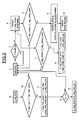
- FIG. 3 illustrates an example of detection of an excess of supercharging pressure, as represented in FIG. 2 between the instants t 1 and t 2 .
- the first integration module INT1 calculates the first sum I 1 (step 1).
- the first comparison module COMP1 compares the first sum I 1 with a sum threshold Iseuil_neg (step 2). If the first sum I 1 is greater than the sum threshold Iseuil_neg, a supercharge excess pressure incident is detected, and the update module MAJ increments by 1 the value of a counter I_neg_compt (step 3).
- I_neg_compt represents the number of detected incidents of excess boost pressure occurring during the present taxi.
- the second comparison module COMP2 compares the value of the counter I_neg_compt with a first predetermined maximum counter value I_neg_compt_seuil (step 4). If the value of the counter I_neg_compt is greater than the first predetermined maximum counter value I_neg_compt_seuil, the second comparison module COMP2 detects a problem of excess of supercharging pressure (step 5), and the module MD of control of operation of the engine in a degraded mode is activated, as well as the AL alarm device (step 6).
- Update module MAJ compares the value of the counter I_neg_compt with a maximum value I_neg_compt_avant (step 7), and if the value of the counter I_neg_compt exceeds the maximum value I_neg_compt_avant, update module update sets the value of the counter I_neg_compt to the maximum value I_neg_compt_avant, and assigns the mileage I_neg_compt_km corresponding to the incrementation of the counter I_neg_compt to a value I_neg_compt_avant_km corresponding to the new maximum value I_neg_compt_avant (step 8).
- Update module MAJ updates a maximum value I_neg_max of the first calculated sum I 1 during rolling (step 9), compares the value I_neg_max to its maximum value I_neg_max_avant during previous runs (step 10), and if I_neg_max is greater than I_neg_max_before, updates its maximum value I_neg_max_avant, as well as the associated mileage I_neg_max_avant_km with the mileage I_neg_max_km corresponding to I_neg_max (step 11).
- the update module MAJ tests whether the difference E x changes from negative to positive (step 12), and if so, updates a maximum value of this difference E_neg_max and the associated mileage (step 13). ). This is particularly interesting for the cases of detection of excess supercharging pressure, and much less for cases of detection of lack of boost pressure, as is the case in FIG.
- FIG. 4 illustrates an example of detecting a lack of boost pressure, as represented in FIG. 2 between instants t 3 and t 4 , similarly to the case of detection of an excess of supercharging pressure illustrated by FIG. figure 3.
- the second integration module INT2 calculates the second sum I 2 (step 20).
- the first comparison module COMP1 compares the second sum I 2 with a sum threshold Iseuil_pos (step 21). If the second sum I 2 is greater than the sum threshold Iseuil_pos, an incident of lack of boost pressure is detected, and the updating module MAJ increments by 1 the value of a counter I_pos_compt (step 22).
- I_pos_compt represents the number of detected incidents of lack of boost pressure occurring during the present taxi.
- the second comparison module COMP2 compares the value of the counter I_pos_compt with a second predetermined maximum counter value I_pos_compt_seuil (step 23). If the value of the counter I_pos_compt is greater than the second predetermined maximum counter value I_pos_compt_seuil, the second comparison module COMP2 detects a problem of lack of boost pressure (step 24), and the engine operation control module MD in a degraded mode is enabled, as well as the alarm device (step 25).
- the updating module MAJ compares the value of the counter I_pos_compt with a maximum value I_pos_compt_avant (step 26), and if the value of the counter I_pos_compt exceeds the maximum value I_pos_compt_avant, the update module update sets the value of the counter I_pos_compt to the maximum value I_pos_compt_avant, and assigns the mileage I_pos_compt_km corresponding to the incrementation of the counter I_pos_compt to a value I_pos_compt_avant_km corresponding to the new maximum value I_pos_compt_avant (step 27).
- the updating module updates a maximum value I_pos_max of the second calculated sum I 2 during the running (step 28), compares the value I_pos_max with its maximum value I_pos_max_avant during the previous runs (step 29), and if I_pos_max is greater than I_pos_max_before, updates its maximum value I_pos_max_before, and the associated mileage I_pos_max_avant_km with the mileage I_pos_max_km corresponding to I_pos_max (step 30).
- the invention thus makes it possible to detect problems of excess or lack of air boost pressure in the engine air, more reliably, regardless of the operation of the engine.
- the invention makes it possible to memorize information relating to overfeeding problems that occurred during vehicle runs, in order to allow an accurate subsequent diagnosis.
Landscapes
- Engineering & Computer Science (AREA)
- Chemical & Material Sciences (AREA)
- Combustion & Propulsion (AREA)
- Mechanical Engineering (AREA)
- General Engineering & Computer Science (AREA)
- Supercharger (AREA)
- Combined Controls Of Internal Combustion Engines (AREA)
Applications Claiming Priority (1)
| Application Number | Priority Date | Filing Date | Title |
|---|---|---|---|
| FR0408582A FR2874056B1 (fr) | 2004-08-03 | 2004-08-03 | Procede et systeme de surveillance de la pression de suralimentation en air d'un moteur a combustion interne de vehicule automobile |
Publications (1)
| Publication Number | Publication Date |
|---|---|
| EP1624175A1 true EP1624175A1 (de) | 2006-02-08 |
Family
ID=34949125
Family Applications (1)
| Application Number | Title | Priority Date | Filing Date |
|---|---|---|---|
| EP05300592A Withdrawn EP1624175A1 (de) | 2004-08-03 | 2005-07-13 | Verfahren und Vorrichtung zur Überwachung eines Aufladedruckes einer Brennkraftmaschine eines Kraftfahrzeugs |
Country Status (2)
| Country | Link |
|---|---|
| EP (1) | EP1624175A1 (de) |
| FR (1) | FR2874056B1 (de) |
Cited By (2)
| Publication number | Priority date | Publication date | Assignee | Title |
|---|---|---|---|---|
| FR2923262A1 (fr) * | 2007-11-06 | 2009-05-08 | Renault Sas | Procede et dispositif de diagnostic de l'etat d'un systeme de commande a ailettes mobiles de la turbine d'un turbocompresseur |
| CN114704399A (zh) * | 2022-03-30 | 2022-07-05 | 潍柴动力股份有限公司 | 一种进气压力可信性诊断方法、装置、车辆及存储介质 |
Citations (6)
| Publication number | Priority date | Publication date | Assignee | Title |
|---|---|---|---|---|
| JPS60222543A (ja) * | 1984-04-18 | 1985-11-07 | Mazda Motor Corp | エンジンの保護装置 |
| DE19625887A1 (de) * | 1996-06-27 | 1998-01-02 | Bayerische Motoren Werke Ag | Turboaufgeladene Brennkraftmaschine mit einer Fehlererkennungseinrichtung |
| DE19804466A1 (de) * | 1998-02-05 | 1999-08-12 | Daimler Chrysler Ag | Verfahren zur Steuerung eines Abgasturboladers mit variabler Turbinengeometrie |
| US6425247B1 (en) * | 1998-09-26 | 2002-07-30 | Daimlerchrysler Ag | Method for controlling a super-charged internal combustion engine |
| US20030084886A1 (en) * | 2001-10-11 | 2003-05-08 | Yoshiyuki Akao | Variable displacement supercharging system and method for detecting abnormality of supercharging system |
| WO2003067060A1 (en) * | 2002-02-05 | 2003-08-14 | Honeywell International Inc. | Control method for variable geometry turbocharger and related system |
-
2004
- 2004-08-03 FR FR0408582A patent/FR2874056B1/fr active Active
-
2005
- 2005-07-13 EP EP05300592A patent/EP1624175A1/de not_active Withdrawn
Patent Citations (6)
| Publication number | Priority date | Publication date | Assignee | Title |
|---|---|---|---|---|
| JPS60222543A (ja) * | 1984-04-18 | 1985-11-07 | Mazda Motor Corp | エンジンの保護装置 |
| DE19625887A1 (de) * | 1996-06-27 | 1998-01-02 | Bayerische Motoren Werke Ag | Turboaufgeladene Brennkraftmaschine mit einer Fehlererkennungseinrichtung |
| DE19804466A1 (de) * | 1998-02-05 | 1999-08-12 | Daimler Chrysler Ag | Verfahren zur Steuerung eines Abgasturboladers mit variabler Turbinengeometrie |
| US6425247B1 (en) * | 1998-09-26 | 2002-07-30 | Daimlerchrysler Ag | Method for controlling a super-charged internal combustion engine |
| US20030084886A1 (en) * | 2001-10-11 | 2003-05-08 | Yoshiyuki Akao | Variable displacement supercharging system and method for detecting abnormality of supercharging system |
| WO2003067060A1 (en) * | 2002-02-05 | 2003-08-14 | Honeywell International Inc. | Control method for variable geometry turbocharger and related system |
Cited By (5)
| Publication number | Priority date | Publication date | Assignee | Title |
|---|---|---|---|---|
| FR2923262A1 (fr) * | 2007-11-06 | 2009-05-08 | Renault Sas | Procede et dispositif de diagnostic de l'etat d'un systeme de commande a ailettes mobiles de la turbine d'un turbocompresseur |
| WO2009060155A2 (fr) * | 2007-11-06 | 2009-05-14 | Renault S.A.S | Procede et dispositif de diagnostic de l'etat d'un systeme de commande a ailettes mobiles de la turbine d'un turbocompresseur |
| WO2009060155A3 (fr) * | 2007-11-06 | 2009-07-02 | Renault Sa | Procede et dispositif de diagnostic de l'etat d'un systeme de commande a ailettes mobiles de la turbine d'un turbocompresseur |
| CN114704399A (zh) * | 2022-03-30 | 2022-07-05 | 潍柴动力股份有限公司 | 一种进气压力可信性诊断方法、装置、车辆及存储介质 |
| CN114704399B (zh) * | 2022-03-30 | 2023-01-06 | 潍柴动力股份有限公司 | 一种进气压力可信性诊断方法、装置、车辆及存储介质 |
Also Published As
| Publication number | Publication date |
|---|---|
| FR2874056B1 (fr) | 2007-02-16 |
| FR2874056A1 (fr) | 2006-02-10 |
Similar Documents
| Publication | Publication Date | Title |
|---|---|---|
| EP2761151B1 (de) | DIAGNOSEVERFAHREN UND SYSTEM FÜR EINe Brennkraftmaschine zweistufiger Aufladung | |
| FR2524557A1 (fr) | Dispositif de controle de cognement pour un moteur a combustion interne | |
| EP2279340B1 (de) | Verfahren zur steuerung eines motors | |
| EP2956651B1 (de) | Verfarhen zur bestimmung des abgasdrucks stromaufwärts eines turboladers und der über dessen turbine fliessenden gasmenge | |
| EP2935828A1 (de) | Diagnoseverfahren für aufgeladenen motor und zugehöriger motor | |
| EP2361349B1 (de) | Verfahren zur dynamischen schätzung der frischluftdurchflussrate, die einem motor mit hochdruck- und niederdruck-agr-kreisen zugeführt wird. | |
| EP1799983B1 (de) | Verbessertes verfahren und system zur schätzung der abgastemperatur und verbrennungsmotor mit einem solchen system | |
| EP1687515B1 (de) | Verfahren zum schätzen einer menge von in das abgas eines dieselmotors eines kraftfahrzeugs abgegebenen teilchen | |
| EP2507494A1 (de) | Verfahren zur überwachung einer zweiphasigen turboladung durch turbolader mit fixer geometrie und einem dynamischen kalkukator sowie vorturbinendruckbegrenzung | |
| EP1624175A1 (de) | Verfahren und Vorrichtung zur Überwachung eines Aufladedruckes einer Brennkraftmaschine eines Kraftfahrzeugs | |
| EP1903203B1 (de) | Vorrichtung und Verfahren zur Feststellung einer Panne in einem Luftaufladungssystem eines Motors | |
| EP2699778B1 (de) | Verfahren zur fehlerdiagnose eines aufgeladenen motors und aufgeladener motor | |
| JP2003232225A (ja) | ある範囲内のエンジンセンサーの故障を検出する方法 | |
| FR2829530A1 (fr) | Procede et systeme de reglage du flux d'air dans le collecteur d'admission d'un moteur a combustion interne d'un vehicule automobile | |
| EP1828578B1 (de) | Verfahren zur steuerung einer aufgeladenen maschine | |
| FR3014145A1 (fr) | Procede de determination de la pression de gaz en amont d'une turbine de suralimentation d'un moteur a combustion interne et systeme d'asservissement mettant en oeuvre un tel procede | |
| FR2905411A1 (fr) | Procede de determination de debut de combustion dans un moteur et vehicule mettant en oeuvre le procede | |
| EP0736680B1 (de) | Verfahren zur Selbstkorrektor von physikalischen Parametern für ein dynamisches System, wie zum Beispiel eine Brennkraftmaschine | |
| KR102119865B1 (ko) | 단기통 4행정 엔진의 실화 진단 방법 및 장치 | |
| FR2963424A1 (fr) | Procede de diagnostic d'une fuite d'air frais comprime dans un moteur a combustion interne | |
| FR2901840A1 (fr) | Procede et systeme de controle d'un dispositif de post-traitement des gaz d'echappement | |
| EP0793778A1 (de) | Verfahren zur rückkehr zur nennzündverstellung in abwesenheit einer klopferkennung | |
| EP2066892B1 (de) | Steuersystem für den verbrennungsmotor eines kraftfahrzeuges mit abgasrückführung mit gesteuertem rückführungsventil | |
| FR2893983A1 (fr) | Procede et systeme d'estimation d'une temperature des gaz d'echappement et moteur a combustion interne equipe d'un tel systeme | |
| WO2023072565A1 (fr) | Procédé d'estimation de la pression atmosphérique pour un moteur à combustion interne |
Legal Events
| Date | Code | Title | Description |
|---|---|---|---|
| PUAI | Public reference made under article 153(3) epc to a published international application that has entered the european phase |
Free format text: ORIGINAL CODE: 0009012 |
|
| AK | Designated contracting states |
Kind code of ref document: A1 Designated state(s): AT BE BG CH CY CZ DE DK EE ES FI FR GB GR HU IE IS IT LI LT LU LV MC NL PL PT RO SE SI SK TR |
|
| AX | Request for extension of the european patent |
Extension state: AL BA HR MK YU |
|
| 17P | Request for examination filed |
Effective date: 20060802 |
|
| AKX | Designation fees paid |
Designated state(s): AT BE BG CH CY CZ DE DK EE ES FI FR GB GR HU IE IS IT LI LT LU LV MC NL PL PT RO SE SI SK TR |
|
| 17Q | First examination report despatched |
Effective date: 20060922 |
|
| GRAP | Despatch of communication of intention to grant a patent |
Free format text: ORIGINAL CODE: EPIDOSNIGR1 |
|
| INTG | Intention to grant announced |
Effective date: 20150213 |
|
| STAA | Information on the status of an ep patent application or granted ep patent |
Free format text: STATUS: THE APPLICATION IS DEEMED TO BE WITHDRAWN |
|
| 18D | Application deemed to be withdrawn |
Effective date: 20150624 |