EP1623922A1 - Système et méthode pour commander des tourbillons de écoulement avec des reseaux de micro-jets - Google Patents
Système et méthode pour commander des tourbillons de écoulement avec des reseaux de micro-jets Download PDFInfo
- Publication number
- EP1623922A1 EP1623922A1 EP05425549A EP05425549A EP1623922A1 EP 1623922 A1 EP1623922 A1 EP 1623922A1 EP 05425549 A EP05425549 A EP 05425549A EP 05425549 A EP05425549 A EP 05425549A EP 1623922 A1 EP1623922 A1 EP 1623922A1
- Authority
- EP
- European Patent Office
- Prior art keywords
- flow
- micro
- aerodynamic surface
- jets
- flow field
- Prior art date
- Legal status (The legal status is an assumption and is not a legal conclusion. Google has not performed a legal analysis and makes no representation as to the accuracy of the status listed.)
- Withdrawn
Links
Images


Classifications
-
- B—PERFORMING OPERATIONS; TRANSPORTING
- B64—AIRCRAFT; AVIATION; COSMONAUTICS
- B64C—AEROPLANES; HELICOPTERS
- B64C21/00—Influencing air flow over aircraft surfaces by affecting boundary layer flow
- B64C21/02—Influencing air flow over aircraft surfaces by affecting boundary layer flow by use of slot, ducts, porous areas or the like
-
- B—PERFORMING OPERATIONS; TRANSPORTING
- B64—AIRCRAFT; AVIATION; COSMONAUTICS
- B64C—AEROPLANES; HELICOPTERS
- B64C2230/00—Boundary layer controls
- B64C2230/18—Boundary layer controls by using small jets that make the fluid flow oscillate
-
- Y—GENERAL TAGGING OF NEW TECHNOLOGICAL DEVELOPMENTS; GENERAL TAGGING OF CROSS-SECTIONAL TECHNOLOGIES SPANNING OVER SEVERAL SECTIONS OF THE IPC; TECHNICAL SUBJECTS COVERED BY FORMER USPC CROSS-REFERENCE ART COLLECTIONS [XRACs] AND DIGESTS
- Y02—TECHNOLOGIES OR APPLICATIONS FOR MITIGATION OR ADAPTATION AGAINST CLIMATE CHANGE
- Y02T—CLIMATE CHANGE MITIGATION TECHNOLOGIES RELATED TO TRANSPORTATION
- Y02T50/00—Aeronautics or air transport
- Y02T50/10—Drag reduction
Definitions
- the present invention relates generally to manipulation of flow field vortices and more particularly, a system and method for manipulating the shedding, size, and trajectory flow field vortices from aerodynamic surfaces with an active array of micro-jets to reduce downstream buffeting and fatigue.
- Vortices generated by fluid flow over aerodynamic surfaces can buffet and fatigue any downstream structure exposed to these vortices.
- Vortices can be generated at the fore body of an aircraft or other upstream structure, and damage control surfaces, engines, after body/empennage, nacelles, turrets, or other structures integrated into the airframe. Additionally, these vortices can be ingested within engine air intakes or other like air inlets leading to poor performance and/or stalling of the aircraft engines. Stalling the aircraft engine creates a potentially hazardous condition.
- Next generation aircraft such as blended wing body, compound this problem by incorporating gas turbine inlets with serpentine spines within the air frame. Additionally, exotic aperture shapes for the inlet and outlet may cause excessive propulsion performance losses. These losses emanate from strong secondary flow gradients in the near wall boundary of the airflow, which produce coherent large-scale vortices.
- Vortex generators are small wing like sections mounted on an aerodynamic surface exposed to the fluid flow and inclined at an angle to the fluid flow to shed the vortices.
- the height chosen for the best interaction between the boundary layer and the vortex generator is usually the boundary layer thickness.
- the principle of boundary layer control by vortex generation relies on induced mixing between the primary fluid flow and the secondary fluid flow. The mixing is promoted by vortices trailing longitudinally near the edge of the boundary layer. Fluid particles with high momentum in the stream direction are swept along helical paths toward the duct surface to mix with and, to some extent replace low momentum boundary layer flow. This is a continuous process that provides a source to counter the natural growth of the boundary layer creating adverse pressure gradients and low energy secondary flow accumulation.
- MEMS Micro-fabricated Electro-Mechanical Systems
- MEMS offer the integration of micro-machined mechanical devices and microelectronics.
- Mechanical components in MEMS like transistors in microelectronics, have dimensions that are measured in microns.
- These electro-mechanical devices may include discrete effectors and sensors.
- the present invention provides a system or method to actively control the size and trajectory flow field vortices with micro-jet arrays that substantially addresses the above-identified needs. More particularly, the present invention provides a system or method for shedding flow field vortices from aerodynamic surfaces with active micro-jet arrays to reduce downstream buffeting and fatigue of components exposed downstream components.
- Manipulating the shedding, size and trajectory of flow field vortices from an aerodynamic surface involves placing micro-jet arrays at the aerodynamic surface.
- the individual micro-jets are oriented generally with the flow direction of the fluid flow.
- These micro-jet arrays induce secondary flow structures within a boundary layer of the fluid flow.
- the secondary flow structures manipulate the shedding, size and trajectory of the flow field vortices from the surface.
- these secondary flow structures or vortices allow the inception point and trajectory and size of the flow field vortices to be actively influenced. By controlling the inception, size, and trajectory of the flow field vortices, it is possible to reduce buffeting and fatigue of downstream components.
- Downstream components may include, but should not be limited to; engine inlets buried within the airframe on next generation aircraft, after body, empennage, missiles, turrets, inlet cowls and wings of an aircraft.
- engine inlets buried within the airframe on next generation aircraft, after body, empennage, missiles, turrets, inlet cowls and wings of an aircraft.
- the structure required to manage the stress loads on the components may be reduced as well.
- a downstream component is an aircraft engine, potentially hazardous conditions can be avoided by preventing the aircraft engine from stalling due to flow field vortices.
- the downstream component is a submerged engine or one with a reduced or eliminated pylon, the vortices may manipulate the boundary layer obscured by the engine inlet.
- Such improvements allow reduced observability, improved control, reduced weight and surface area by reducing the pylon or nacelle.
- micro-jet arrays may be located anywhere along the aerodynamic surface, one embodiment locates the micro-jets within a receptive zone along the leading edge of aerodynamic surfaces in order to increase the micro-jet's leverage to influence the inception point and trajectory of the flow field vortices.
- These micro-jets may employ a continuous flow bled from the primary flow or pulsed flows from micro-jets.
- MEMS offer the integration of micro-machined mechanical devices and microelectronics. Mechanical components in MEMS, like transistors in microelectronics, have dimensions that are measured in microns. These electro-mechanical devices may include discrete effectors and sensors.
- Another embodiment senses the flow conditions over the aerodynamic surface. This information is compared with desired fluid flow conditions to actively and dynamically control the micro-jet arrays in order to achieve a desired fluid flow.
- Another implementation provides a method to reduce the effect of flow field vortices generated along the surfaces of an upstream vehicle on a downstream vehicle.
- This involves placing micro-jet arrays on aerodynamic surfaces of the upstream vehicle. These micro-jet arrays are generally oriented with the mean flow direction of the fluid flow over the upstream vehicle's aerodynamic surfaces.
- Micro-jet arrays introduce secondary flow structures within the boundary layer of the fluid flow over the upstream vehicle. These secondary flow structures influence the inception point, size, and trajectory of flow field vortices associated with the upstream vehicle. By properly directing flow field vortices laterally outward from the upstream vehicle, the separation in time and space between the vehicles may be reduced. This may help improve traffic problems encountered in congested airways.
- Yet another embodiment provides an aerodynamic surface or control surface operable to manipulate flow field vortices over the aerodynamic surface.
- This aerodynamic surface comprises micro-jet arrays located substantially upstream of fluid flow over the majority of the aerodynamic surface. These micro-jet arrays introduce secondary flows in the near wall boundary layer to influence or manipulate the inception point, size, and trajectory of flow field vortices over the aerodynamic surface. Sensors detect fluid flow characteristics over the aerodynamic surface.
- a control system operably coupled to the micro-jet arrays and sensors directs the micro-jet arrays to actively introduce the secondary flows in order to achieve a desired fluid flow over the aerodynamic surface.
- the micro-jet arrays may be located anywhere on the surface, the array's leverage may be increased by placement within a receptive zone or leading edge.
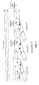
- FIG. 1 depicts an array of micro-jets operable to introduce secondary flow structures in accordance with the present invention
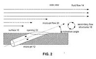
- FIG. 2 provides a cross-section view of a micro-jet embedded within an aerodynamic surface in accordance with the present invention
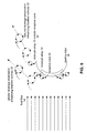
- FIG. 3 provides a plan view of a micro-jet embedded within an aerodynamic surface over which a fluid flows in accordance with the present invention
- FIG. 4 depicts an aircraft utilizing an array of micro-jets to influence flow-field vortices in accordance with the present invention
- FIG. 5 depicts a cross-section of a leading edge wherein micro-jet arrays are preferentially placed in a receptive zone to influence flow-field vortices in accordance with the present invention
- FIG. 6 provides a plan view of an aerodynamic surface wherein micro-jet arrays are placed along the leading edge to influence to realize increased leverage over influencing flow-field vortices in accordance with the present invention
- FIGs. 7A, 7B and 7C depict a cross section of a next generation aircraft, such as a blended wing body, having micro-jet arrays operable to minimize the impact of boundary layers on engines located near or submerged within the upper surface of the airframe.
- FIG. 8 depicts an aircraft having micro-jet arrays operable to minimize potential safety hazards caused by flow-field vortices created over the aircraft and their impact on downstream aircraft;
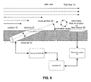
- FIG. 9 provides a functional diagram of an aerodynamic surface or control surface operable to sense flow conditions and influence flow-field vortices over the aerodynamic surface in accordance with the present invention
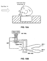
- FIGs. 10A-10D depict various potential micro-jets or like devices
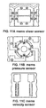
- FIGs. 11A-11C depict various potential sensors
- FIG. 12 provides a logic flow diagram illustrating one embodiment of the present invention.
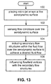
- FIG. 13 provides a logic flow diagram depicting one methodology for influencing flow-field vortices in accordance with the present invention.
- the present invention provides a system and method for manipulating aerodynamic or hydrodynamic fluid flow over a surface that substantially eliminates or reduces disadvantages and problems associated with previously developed systems and methods. More specifically, the present invention provides a system and method to prevent or minimize exposure of downstream components to buffeting or fatigue through the use of very-small-scale arrays of jets (micro-jets).
- This system and method includes the placement of micro jet arrays on surfaces bounding the fluid flow. These very-small-scale effectors manipulate the flow behavior of the fluid flow, influence the inception point, size, and trajectory of flow field vortices within the fluid flow, and reduce flow separation within the primary fluid flow.
- FIG. 1 depicts an array 10 of micro-jets 12.
- Micro-jets 12 are embedded in aerodynamic surface 16 over which fluid flow 14 flows.
- the micro-jets 12 introduce a micro-jet flow 20 that causes secondary flow structures 18 to form in the near wall boundary layer between fluid flow 14 and aerodynamic surface 16.
- micro-jets 12 are oriented generally with fluid flow 14.
- the micro-jets 12 generally are not oriented parallel with fluid flow 14.
- micro-jet 12 and its opening 22 are oriented at an inclination angle to produce a micro-jet flow 20 at an acute inclination angle to fluid flow 14. This allows secondary flow structures 18 to be created and not trapped.
- micro-jets 12 introduce secondary flow structures 18 that influence the inception point, size, and trajectory of flow field vortices within fluid flow 14. If micro-jets 12 are oriented at greater angles, trapped secondary flow structures may be produced in the boundary layer between fluid flow 14 and aerodynamic surface 16. These trapped secondary flow structures may create a virtual aerodynamic surface.
- FIG. 3 shows a top down or plan view of aerodynamic surface 16 wherein micro-jets 12 are oriented to produce a micro-jet flow 20 at an azimuth angle to fluid flow 14.
- Micro-jet flows 20 induce secondary flow structures 18 within the boundary layer between the fluid flow 14 and aerodynamic surface 16. Secondary flow structures 18 may laterally manipulate the shedding of flow field vortices from aerodynamic surface 16.
- micro-jet arrays to a vehicle, such as but not limited to aircraft.
- aerodynamic surface 16 is located on an aircraft.
- Other aerodynamic vehicles such as automobiles, trucks, trains, and boats that are sensitive to aerodynamic constraints may have the micro-jet array applied to address aerodynamic concerns and improve the aerodynamic performance of these vehicles.
- FIG. 4 depicts aircraft 30 that experiences flow field vortices 32.
- These flow field vortices are generated from the trailing edge of external components on the aircraft.
- These flow field vortices can adversely affect downstream components of the aircraft such as but not limited to engines, weapons, fuel or storage nacelles, after body structures, such as the tail or empennage, control surfaces, canards, wings, air intake inlets, such as engine air inlets or sensor air inlets, or other downstream components known to those skilled in the art.
- FIG. 4 specifically shows that discontinuities in the aircraft's surface, such as those at the cockpit, can generate flow field vortices 32.
- Wing 34 is also shown to generate flow field vortices 32.
- micro-jet array 10 of micro-jets 12 has been placed on the leading edge of wing 34.
- These micro-jets introduce micro-jet flows 20 that in turn induce secondary flow structures 18.
- These secondary flow structures may influence the inception point, size, and trajectory of flow field vortices away from downstream components as shown.
- flow field vortices 32, located over wing 34, if left unimpeded, would buffet empennage 42. However, these vortices are shifted outwards by the effect of the secondary flow structures 18.
- the structural requirements for these components may be reduced. Additionally, should the flow field vortices be ingested within an air inlet potentially hazardous stresses can be placed on the aircraft engine resulting in stalling or component failure. For example, turbine blades within the aircraft engine may be severely stressed when ingesting flow field vortices. Thus, the performance of aircraft 30 may be improved significantly by actively shedding the flow field vortices 32 in such a manner to reduce stresses on downstream components. As will be discussed in FIGS. 7A and 7B, actively controlling the vortices may greatly improve the performance of aircraft that locate engines near the upper surface of or submerge the engines within the airframe.
- FIG. 5 shows a cross section of the leading edge of wing 34.
- the flow field vortices are shown to be placed in a receptive zone 50 along the out edge of leading edge 36.
- a micro-jet array 10 is shown located outside the receptive zone 50.
- micro-jet arrays may be placed at any location within aerodynamic surface 16, it may be preferential to specifically place micro-jet arrays within receptive zones along the leading edges or other locations of the aerodynamic surface in order to realize an increased leverage in influencing flow field vortices away from downstream components.
- FIG. 6 depicts a plan view of wing 34 within fluid flow 14. Again one observes that micro-jet array 10 and individual micro-jets 12 are located along the leading edge 36 to provide increased lateral leverage over flow field vortices 32. This increases the ability of secondary flow structures 18 to reduce the negative impacts of flow field vortices 32 on downstream components.
- FIGs. 7A, 7B, and 7C depict a cross-section of a next-generation aircraft such as the blended wing body (BWB) where the engine inlets are placed near the upper surface or submerged within the upper surface on the aft section of the aircraft.
- aircraft 52 has the engine 54 located near the aft portion of the aircraft.
- FIG. 7A depicts engine 54 being mounted on a pylon 56 but located near the upper surface 58 of aircraft 52. Mounting above but near the upper surface avoids some problems associated with ingesting boundary layer flow (low energy boundary layer air) at or near upper surface 58.
- FIG. 7B depicts an instance where engine 54 is mounted at the surface to eliminate the pylon or nacelle supporting engine 54.
- FIG. 7C depicts the instance where an engine 54 is submerged within the upper surface 58 of aircraft 52.
- micro-jet arrays 62 are used to actively control and manipulate the boundary layer as seen by inlet 64 of engine 54. These micro-jet arrays 62 may use continuous or pulsating air jets for boundary layer control. These micro-jets manipulate the shedding, size, and trajectory of vorticles as well as the boundary layer to improve the performance of engine 54. Previous solutions may have merely used static vortex generators to manipulate the boundary layer and flow structures ingested by the engines.
- the micro-jets located forward of the inlets to engine 54 can significantly reduce distortion of the airflow ingested by these engines. This may reduce the portion of the lower energy boundary layer ingested by an engine located near the surface or submerged within the surface of the airframe. By reducing the amount of low energy boundary layer air ingested by the engine, the drag reduction experienced by ingesting the low energy boundary layer fluid may be reduced. Thus, the present invention can significantly improve the performance of a vehicle such as a next-generation aircraft like the BWB if engine inlet distortion can be controlled.
- FIG. 8 illustrates this potential hazard.
- upstream aircraft 70 generates uninfluenced flow field vortices 74.
- upstream aircraft 70 and downstream aircraft 72 are separated in time and space.
- the flow field vortices may be modified as shown by modified flow field vortices 76.
- modified flow field vortices 76 By changing the trajectory or strength of the flow field vortices, the separation in time and space between upstream aircraft 70 and downstream aircraft 72 may be reduced.
- the potential safety hazards associated with densely flown routes can be reduced by directing the flow field vortices of aircraft outwards from the longitudinal axis of the aircraft decreasing the longitudinal separation in time and space between aircraft.
- FIG. 9 depicts an aerodynamic surface or control surface 16.
- arrays 10 of micro-jets 12 are located substantially upstream of fluid flow 14 over surface 16.
- Micro-jets 12 introduce micro-jet flow 20 to create secondary flow structures 18 in the near wall boundary layer.
- the secondary flows structures 18 can reduce boundary layer separation over the aerodynamic surface.
- a control system such as micro-jet controller 86, may be operably coupled to micro-jets 12. This control system is operable to actively direct micro-jets 12 to introduce secondary flows 18 in order to achieve a desired fluid flow 14 over aerodynamic surface 16.
- This active control may be further complemented by a sensing system operably coupled to the micro-jet controllers.
- This sensing system may employ flow sensors 80 located at various locations along aerodynamic surface 16. These flow sensors are operable to detect the characteristics of fluid flow 14 over aerodynamic surface 16. Sensor outputs are provided to flow sensor system 82 and processor 84.
- Processor 84 compares the detected fluid flow characteristics over aerodynamic surface 16 with a desired fluid flow characteristic. Then processor 84 will actively direct micro-jet controller 86 to introduce secondary flows 18 to achieve a desired fluid flow over aerodynamic surface 16.
- Processor 84 and controller 86 may be a single processing device or a plurality of processing devices.
- a processing device may be a microprocessor, micro-controller, digital signal processor, microcomputer, central processing unit, field programmable gate array, programmable logic device, state machine, logic circuitry, analog circuitry, digital circuitry, and/or any device that manipulates signals (analog and/or digital) based on operational instructions.
- these micro-jets and flow sensors may be incorporated in any aerodynamic surface. However, in many instances, more value may be realized by placing these systems within receptive zones of the aerodynamic surface such as the leading edge of the aerodynamic surfaces.
- the desired fluid flow may avoid having flow field vortices adversely impact downstream components.
- the desired fluid flow also reduces the fatigue or buffeting of downstream components.
- micro-jets are very-small-scale devices. In some embodiments theses jets are on the order of one-tenth of the boundary layer thickness. These micro-jets may be miniature vortex generators or vortex generator jets fabricated in many ways and applied as an appliqué to or cast into the surface.
- the micro-jets may be miniature fluidic jets that introduce momentum in the form of micro-jet flows 20. These micro-jet flows may be continuous or pulsed and may be bled from the primary flow associated with an engine.
- Micro-jets may also be micro fabricated mechanical structures incorporated on or in the aerodynamic surface. These may also be synthetic pulsators. Other similarly sized jets, known to those skilled in the art, may also be used as the micro-jets.
- FIGs. 10A-10D illustrate many examples of micro fabricated electro-mechanical structures (MEMS) which may be used as these micro-jets.
- FIG. 10A depicts a fluidic effector creating secondary flows structures 18 as primary fluid flow 14 passes over fluidic effector.
- FIG. 10B depicts a pulsing effector.
- a fluidic oscillator alternates flow between two outflow legs by injecting high pressure on either side of the nozzle orifice. Injecting at Input 1 causes flow to exit the device at Output 2, and injecting at Input 2 causes flow to exit the device at Output 1.
- the Input flow can come from a like, but smaller device (Second Stage) or from a mechanically driven valve (First Stage).
- FIG. 10C depicts a synthetic jet effector.
- This type of effector uses a vibrating diaphragm, which bounds a cavity to generate an air jet. The oscillating surface draws fluid into the cavity from all directions and then expels it in a narrow jet. The resultant pulsed jet has no net mass flow.
- FIG. 10D presents a micro-bubble effector where micro-bubbles expand based on internal pressure to manipulate secondary flow structures 18.
- the effectors listed above are examples of possible MEMS devices, which may be used to manipulate primary fluid flow.
- Sensor system 82 may receive input from conventional flow sensors or micro fabricated electro-mechanical sensor devices such as those illustrated in FIGS. 11A, 11B and 11C.
- FIG. 11A depicts sensor 80 as a MEMS sheer sensor. This device functions in a manner similar to a hot-film sheer stress sensor. A small surface flush with the duct wall is maintained at a constant temperature. The heat flex at the duct wall is then measured. This heat flux can be calibrated to sheer stress.
- FIG. 11 B depicts sensor 80 as a MEMS pressure sensor.
- FIG. 11C depicts sensor 80 as a velocity sensor. This device functions in a manner similar to hot-wire anemometers. Electric current is passed through a metal element exposed to the fluid flow. The fluid flow convectively cools the element, effecting a change in its electric resistance. This change in resistance can be related to the velocity magnitude at the sensor through calibration.
- These sensors may be incorporated into surface 16 and communicate to sensor system 82, processor 84 and micro-jet controller 86.
- Another embodiment provides an aerodynamic control surface that actively manipulates the inception point, size and trajectory of flow field vortices and/or boundary layer separation over the aerodynamic control surface.
- This aerodynamic control surface will have micro-jet arrays located substantially upstream of fluid flow over the control surface. These micro-jet arrays introduce secondary flows in the near wall boundary layer. These secondary flows reduce boundary layer separation over the aerodynamic control surface. By reducing boundary layer separation, the overall size of the control surface as well as support for the control surface may be reduced. In an aircraft, for example, this may result in significant weight reduction as the structural requirements associated with the aircraft control surfaces and their control systems may be reduced.
- a control system operably coupled to the micro-jet arrays may direct micro-jet arrays to introduce secondary flows in order to achieve desired fluid flow over the control surface.
- the aerodynamic surfaces of the aircraft are operable to manipulate flow field vortices over the aircraft's aerodynamic surfaces. This reduces buffeting of downstream structures and components of the aircraft.
- An active control system may operably couple to the micro-jet arrays to direct the operation of the micro-jets. Thus, it is not always necessary to have the micro-jet arrays on. Depending on the angle of attack and velocity of the aircraft, the flow field vortices may not always cause fatigue and buffeting of downstream components.
- FIG. 12 provides a logic flow diagram illustrating a method associated with the present invention. Generically, this method involves placing the micro-jet arrays at the aerodynamic surface in step 90. Then, in step 92, secondary flow structures are induced within the fluid flow over the aerodynamic surface by the micro-jet arrays. In Step 94, flow field vortices within the fluid flow over the aerodynamic surface are influenced by the secondary flow structures. The secondary flow structures may specifically influence the inception point and trajectory of the flow field vortices.
- FIG. 13 provides a second logic flow diagram depicting the methodology associated with the present invention.
- micro-jet arrays are placed at the aerodynamic surface.
- sensors at the aerodynamic surface sense flow conditions over the aerodynamic surface in step 102.
- the sensed flow conditions are used to direct micro-jet arrays placed in Step 100 to induce secondary flow structures in step 104 within the fluid flow in order to achieve the desired fluid flow.
- the induced secondary flow structures influence the flow field vortices within the fluid flow in Step 106.
- the present invention enables new and improved designs of low-observable tactical aircraft by allowing unconventionally aerodynamic shapes.
- Low-observable in part takes into consideration such as detection by radar and the radar cross-section associated with a low-observable aircraft.
- One method to detect aircraft involves the use of radar. However, not all objects or aircraft reflect the same amount of radar waves, as is known by those skilled in the art. In a low-observable aircraft one would want to reflect as little radar energy as possible to a radar receiver, enabling the plane to go undetected at closer ranges.
- the amount of radar energy that is reflected by an object can be defined by its radar cross-section.
- To define the radar cross-section of a target one calculates the size of a sphere, which would reflect the same amount of radar energy as the aircraft that was measured.
- the radar cross-section in the square meters is then the area of a circle of the same diameter as the imaginary sphere.
- Radar cross-section is not necessarily defined by aircraft size, but is more closely related to its design and construction. Curved surfaces reflect energy in many directions. Therefore, curved surfaces have been historically avoided in favor of flat surfaces. Flat surfaces, like the facets of a diamond, reflect energy in the limited directions of the designers' choice-namely, away from detecting receivers for a low observable aircraft. As the computation power of computers have increased designers need no longer be limited to faceted surfaces, rather surfaces, including curved surfaces, may be modeled and optimized to minimize the amount of radar energy reflected to a detecting receiver.
- These devices may be used in a low-observable aircraft surfaces or unconventionally shaped surfaces.
- static architectural structures such as buildings, bridges, and towers may incorporate these devices in their aerodynamic surfaces.
- Unconventionally shaped surfaces may include aggressive duct offsets. The enhancement of fluid flow 14 over these unconventionally shaped surfaces can help to minimize the size, weight, and structural support required by these surfaces.
- Fluid flow control can be used to mitigate any performance impact on the aircraft. Additionally, attack geometries and sensing internal and external flow conditions at the aircraft and actively manipulating the fluid flow conditions at the aircraft to achieve desired fluid flow conditions at the aircraft will enhance dynamic conditions of the aircraft in flight. Fluid flow may be manipulated to meet several objectives including: (1) reduced component fatigue, (2) stable fluid flow within an internal ducting system, and (3) stable fluid flow external to the aircraft in dynamic geometries.
- flow control can reduce cyclic fatigue of components located within fluid flow 14. Stress peak amplitudes experienced by a component within the fluid flow for a normal flow can be greatly reduced by reducing or eliminating interactions between flow field vortices and structural components.
- the present invention may be used to improve flow behavior in a hydrodynamic application. This may minimize head loss in a piping system, reduce flow noise within a piping system or over a submerged structure or to control and manipulate hydrodynamic flow about a watercraft for direction and thrust control.
- FIG. 1 Further embodiments of the present invention may include air-handling units such as HVAC systems, chemical processors, automobile air intake manifold or biomedical applications.
- HVAC systems such as HVAC systems, chemical processors, automobile air intake manifold or biomedical applications.
- the present invention should not be limited to these applications.
- the term “substantially” or “approximately”, as may be used herein, provides an industry-accepted tolerance to its corresponding term. Such an industry-accepted tolerance ranges from less than one percent to twenty percent and corresponds to, but is not limited to, component values, integrated circuit process variations, temperature variations, rise and fall times, and/or thermal noise.
- the term “operably coupled”, as may be used herein, includes direct coupling and indirect coupling via another component, element, circuit, or module where, for indirect coupling, the intervening component, element, circuit, or module does not modify the information of a signal but may adjust its current level, voltage level, and/or power level.
- inferred coupling includes direct and indirect coupling between two elements in the same manner as “operably coupled”.
- the term "compares favorably”, as may be used herein indicates that a comparison between two or more elements, items, signals, etc., provides a desired relationship. For example, when the desired relationship is that signal 1 has a greater magnitude than signal 2, a favorable comparison may be achieved when the magnitude of signal 1 is greater than that of signal 2 or when the magnitude of signal 2 is less than that of signal 1.
Landscapes
- Engineering & Computer Science (AREA)
- Aviation & Aerospace Engineering (AREA)
- Aerodynamic Tests, Hydrodynamic Tests, Wind Tunnels, And Water Tanks (AREA)
Applications Claiming Priority (1)
| Application Number | Priority Date | Filing Date | Title |
|---|---|---|---|
| US10/909,615 US7510149B2 (en) | 2004-08-02 | 2004-08-02 | System and method to control flowfield vortices with micro-jet arrays |
Publications (1)
| Publication Number | Publication Date |
|---|---|
| EP1623922A1 true EP1623922A1 (fr) | 2006-02-08 |
Family
ID=35149491
Family Applications (1)
| Application Number | Title | Priority Date | Filing Date |
|---|---|---|---|
| EP05425549A Withdrawn EP1623922A1 (fr) | 2004-08-02 | 2005-07-27 | Système et méthode pour commander des tourbillons de écoulement avec des reseaux de micro-jets |
Country Status (2)
| Country | Link |
|---|---|
| US (2) | US7510149B2 (fr) |
| EP (1) | EP1623922A1 (fr) |
Cited By (7)
| Publication number | Priority date | Publication date | Assignee | Title |
|---|---|---|---|---|
| FR2908167A1 (fr) * | 2006-11-03 | 2008-05-09 | Centre Nat Rech Scient | Dispositif pour retarder le decollement d'une couche limite |
| WO2011009633A1 (fr) * | 2009-07-23 | 2011-01-27 | Airbus Operations Gmbh | Actionneur fluidique destiné à produire un écoulement de sortie pulsé dans le contournement d'un corps aérodynamique, et dispositif de purge et corps aérodynamique ainsi équipés |
| WO2011092429A1 (fr) | 2010-01-27 | 2011-08-04 | Centre National De La Recherche Scientifique - Cnrs | Procede et dispositif de modulation du debit massique d'un ecoulement de gaz |
| CN102320375A (zh) * | 2011-06-27 | 2012-01-18 | 南京航空航天大学 | 一种飞行器前体非对称涡控制装置及其控制方法 |
| CN102417032A (zh) * | 2011-10-20 | 2012-04-18 | 南京航空航天大学 | 大攻角非对称涡变频射流振荡器非定常主动控制装置 |
| EP2671784B1 (fr) * | 2012-06-04 | 2016-07-13 | Honda Motor Co., Ltd. | Appareil pour réduire la traînée aérodynamique d'un véhicule |
| EP4071052A1 (fr) | 2021-04-06 | 2022-10-12 | Siec Badawcza Lukasiewicz-Instytut Lotnictwa | Système et procédé de contrôle actif de l'écoulement sur la surface aérodynamique |
Families Citing this family (63)
| Publication number | Priority date | Publication date | Assignee | Title |
|---|---|---|---|---|
| DE60317556D1 (de) * | 2002-11-25 | 2007-12-27 | Nikolaus Vida | Verfahren und vorrichtung zur mischung von fluiden in einer grenzschicht |
| US8016244B2 (en) * | 2004-02-20 | 2011-09-13 | The Boeing Company | Active systems and methods for controlling an airfoil vortex |
| US7661629B2 (en) * | 2004-02-20 | 2010-02-16 | The Boeing Company | Systems and methods for destabilizing an airfoil vortex |
| US20060196638A1 (en) * | 2004-07-07 | 2006-09-07 | Georgia Tech Research Corporation | System and method for thermal management using distributed synthetic jet actuators |
| US20060102801A1 (en) * | 2004-11-01 | 2006-05-18 | The Boeing Company | High-lift distributed active flow control system and method |
| SE528351C2 (sv) * | 2005-01-27 | 2006-10-24 | Wm Data Caran Ab | Förbättringar av landfordons aerodynamiska egenskaper |
| EP1690788A1 (fr) * | 2005-02-15 | 2006-08-16 | C.R.F. Società Consortile per Azioni | Un avion des dimensions compactes |
| US7686257B2 (en) * | 2005-05-23 | 2010-03-30 | Lockheed Martin Corporation | Dual bimorph synthetic pulsator |
| US7635107B2 (en) * | 2005-08-09 | 2009-12-22 | The Boeing Company | System for aerodynamic flows and associated method |
| US8033510B2 (en) * | 2005-08-09 | 2011-10-11 | The Boeing Company | Lift augmentation system and associated method |
| US7967258B2 (en) * | 2005-10-06 | 2011-06-28 | Lockheed Martin Corporation | Dual bimorph synthetic pulsator |
| US7607470B2 (en) * | 2005-11-14 | 2009-10-27 | Nuventix, Inc. | Synthetic jet heat pipe thermal management system |
| US8030886B2 (en) | 2005-12-21 | 2011-10-04 | Nuventix, Inc. | Thermal management of batteries using synthetic jets |
| US7637455B2 (en) * | 2006-04-12 | 2009-12-29 | The Boeing Company | Inlet distortion and recovery control system |
| WO2008004476A1 (fr) * | 2006-07-06 | 2008-01-10 | Panasonic Corporation | Dispositif pour capteur cellulaire électrophysiologique, capteur cellulaire électrophysiologique utilisant le dispositif, et procédé de fabrication du dispositif pour capteur cellulaire électrophysiologique |
| US7686253B2 (en) * | 2006-08-10 | 2010-03-30 | The Boeing Company | Systems and methods for tracing aircraft vortices |
| EP2426342B1 (fr) * | 2006-10-12 | 2018-02-28 | United Technologies Corporation | Turboréacteur à double flux doté d'une zone de sortie variable et procédé de fonctionnement |
| US9002484B2 (en) * | 2006-12-01 | 2015-04-07 | The Invention Science Fund I Llc | System and method for deforming surfaces |
| US8074939B2 (en) * | 2006-12-01 | 2011-12-13 | The Invention Science Fund I, Llc | Active control of surface drag |
| US8783337B2 (en) | 2006-12-01 | 2014-07-22 | The Invention Science Fund I Llc | System for changing the convective heat transfer coefficient for a surface |
| US8074938B2 (en) | 2006-12-01 | 2011-12-13 | The Invention Science Fund I, Llc | Active control of a body by altering surface drag |
| US9157368B2 (en) * | 2007-09-05 | 2015-10-13 | United Technologies Corporation | Active flow control for nacelle inlet |
| GB0908540D0 (en) * | 2009-05-19 | 2009-06-24 | Rolls Royce Plc | A gas turbine engine having a nacelle and a breather duct |
| GB0919107D0 (en) * | 2009-11-02 | 2009-12-16 | Rolls Royce Plc | A boundary layer energiser |
| GB0919115D0 (en) * | 2009-11-02 | 2009-12-16 | Rolls Royce Plc | Breather duct shielding |
| GB0919110D0 (en) * | 2009-11-02 | 2009-12-16 | Rolls Royce Plc | A boundary layer energiser |
| CN102712360B (zh) * | 2009-12-21 | 2015-08-05 | 雷蒙特亚特特拉维夫大学有限公司 | 振荡涡旋发生器及其应用 |
| US8887482B1 (en) * | 2010-02-12 | 2014-11-18 | The Boeing Company | Active flow control with pulse detonation actuators |
| DE102010026162A1 (de) * | 2010-07-06 | 2012-01-12 | Airbus Operations Gmbh | Flugzeug mit Tragflügeln und einem System zur Minimierung des Einflusses von instationären Anströmzuständen |
| US8561935B2 (en) * | 2010-09-17 | 2013-10-22 | Karl F. Milde, Jr. | STOL and/or VTOL aircraft |
| DE102010046667A1 (de) * | 2010-09-27 | 2012-03-29 | Airbus Operations Gmbh | Fluid-Aktuator zur Beeinflussung der Strömung entlang einer Strömungsoberfläche sowie Ausblasvorrichtung und Strömungskörper mit einem solchen Fluid-Aktuator |
| US8857761B2 (en) | 2010-10-27 | 2014-10-14 | Ata Engineering, Inc. | Variable geometry aircraft pylon structure and related operation techniques |
| US20170088254A1 (en) * | 2011-03-10 | 2017-03-30 | RuiQing Hong | Ultra-High-Pressure Fluid Injection Dynamic Orbit-Transfer System and Method |
| US9514734B1 (en) | 2011-06-30 | 2016-12-06 | The United States Of America As Represented By The Administrator Of National Aeronautics And Space Administration | Acoustic liners for turbine engines |
| US9567867B2 (en) | 2011-09-14 | 2017-02-14 | Ata Engineering, Inc. | Methods and apparatus for deployable swirl vanes |
| US8967311B2 (en) | 2011-12-01 | 2015-03-03 | Paccar Inc. | Directed gas systems for improving aerodynamics of a vehicle in cross wind conditions |
| US8950534B2 (en) | 2011-12-01 | 2015-02-10 | Paccar Inc | Directed air systems for improving aerodynamics of a vehicle |
| KR101957943B1 (ko) * | 2012-08-31 | 2019-07-04 | 삼성전자주식회사 | 정보 제공 방법 및 이를 위한 정보 제공 차량 |
| US20160122005A1 (en) | 2013-03-11 | 2016-05-05 | United Technologies Corporation | Embedded engines in hybrid blended wing body |
| US20160152324A1 (en) * | 2013-04-01 | 2016-06-02 | California Institute Of Technology | Fluidic fence for performance enhancement |
| CN104156507B (zh) * | 2014-07-23 | 2017-05-24 | 西北工业大学 | 一种用于飞机部件易损性排序的方法 |
| US9891677B2 (en) * | 2014-09-11 | 2018-02-13 | Dell Products L.P. | Skin based system cooling using internal system fan |
| US9714083B2 (en) | 2015-05-06 | 2017-07-25 | The Boeing Company | Color applications for aerodynamic microstructures |
| US9868135B2 (en) | 2015-05-06 | 2018-01-16 | The Boeing Company | Aerodynamic microstructures having sub-microstructures |
| US9751618B2 (en) | 2015-05-06 | 2017-09-05 | The Boeing Company | Optical effects for aerodynamic microstructures |
| US10099771B2 (en) * | 2016-03-14 | 2018-10-16 | The Boeing Company | Aircraft wing structure and associated method for addressing lift and drag |
| WO2017189474A1 (fr) * | 2016-04-25 | 2017-11-02 | Rensselaer Polytechnic Institute | Procédés et appareil de commande de champs d'écoulement |
| US10105877B2 (en) | 2016-07-08 | 2018-10-23 | The Boeing Company | Multilayer riblet applique and methods of producing the same |
| US10837362B2 (en) | 2016-10-12 | 2020-11-17 | General Electric Company | Inlet cowl for a turbine engine |
| US10914559B1 (en) | 2016-11-21 | 2021-02-09 | Lockheed Martin Corporation | Missile, slot thrust attitude controller system, and method |
| US10113844B1 (en) | 2016-11-21 | 2018-10-30 | Lockheed Martin Corporation | Missile, chemical plasm steering system, and method |
| EP3759393B1 (fr) * | 2018-02-27 | 2022-03-30 | Potsdam-Institut für Klimafolgenforschung E.V. | Procédé servant à minimiser des instabilités thermoacoustiques d'une turbine à gaz |
| WO2020023395A1 (fr) | 2018-07-24 | 2020-01-30 | Deep Science, Llc | Systèmes et procédés de régulation active de traînée de surface |
| CN108820186B (zh) * | 2018-07-27 | 2023-11-07 | 中国科学院工程热物理研究所 | 基于流场控制的无人机控制装置及无人机 |
| US11353240B2 (en) | 2018-10-02 | 2022-06-07 | United States Of America As Represented By The Administrator Of Nasa | Low drag, variable-depth acoustic liner |
| WO2020097114A1 (fr) | 2018-11-06 | 2020-05-14 | Deep Science, Llc | Systèmes et procédés de régulation active de traînée de surface à l'aide de couplage de paroi |
| US11434945B2 (en) * | 2018-11-15 | 2022-09-06 | Ramot At Tel Aviv Universitv Ltd. | Device and method for creating a distribution of unsteady suction |
| EP3887249B1 (fr) | 2018-11-30 | 2023-04-26 | Deep Science, LLC | Systèmes et procédés de commande active de résistance de frottement à l'aide d'une génération d'ondes sélective |
| CN110615090B (zh) * | 2019-10-14 | 2022-06-14 | 中国空气动力研究与发展中心计算空气动力研究所 | 一种改善飞机平尾翼根部位流场品质可伸缩控制喷气装置 |
| WO2021150755A1 (fr) * | 2020-01-23 | 2021-07-29 | Deep Science, Llc | Systèmes et procédés de commande active de traînée de surface à l'aide d'un actionnement intermittent ou variable |
| US11905983B2 (en) | 2020-01-23 | 2024-02-20 | Deep Science, Llc | Systems and methods for active control of surface drag using electrodes |
| EP4294720A1 (fr) | 2021-02-17 | 2023-12-27 | Enterprise Science Fund, Llc | Injection d'impulsion transverse dans le plan pour perturber des tourbillons à grande échelle dans une couche limite turbulente |
| US11987021B2 (en) | 2021-09-01 | 2024-05-21 | The Boeing Company | Multilayer riblet appliques |
Citations (6)
| Publication number | Priority date | Publication date | Assignee | Title |
|---|---|---|---|---|
| US4655419A (en) * | 1984-12-31 | 1987-04-07 | The Boeing Company | Vortex generator |
| US4696442A (en) * | 1986-07-14 | 1987-09-29 | The Boeing Company | Vortex generators for inlets |
| US4706902A (en) * | 1982-08-11 | 1987-11-17 | Office National D'etudes Et De Recherche Aerospatiales | Active method and installation for the reduction of buffeting of the wings of an aircraft |
| US5758823A (en) * | 1995-06-12 | 1998-06-02 | Georgia Tech Research Corporation | Synthetic jet actuator and applications thereof |
| WO2001006134A1 (fr) * | 1999-07-16 | 2001-01-25 | Lockheed Martin Corporation | Systeme et procede de manipulation et de regulation d'un ecoulement fluide sur une surface |
| WO2002072421A2 (fr) * | 2001-03-10 | 2002-09-19 | Georgia Tech Research Corporation | Modification de l'ecoulement dun fluide sur des corps et des surfaces par formage aerodynamique virtuel de profils au moyen d'actuateurs de jets synthetiques |
Family Cites Families (9)
| Publication number | Priority date | Publication date | Assignee | Title |
|---|---|---|---|---|
| US3881669A (en) * | 1973-05-16 | 1975-05-06 | Martin Lessen | Method and apparatus for elimination of airfoil trailing vortices |
| US4697769A (en) * | 1984-04-23 | 1987-10-06 | Flow Industries, Inc. | Method and apparatus for controlling bound vortices in the vicinity of lifting surfaces |
| US5114102A (en) * | 1989-10-06 | 1992-05-19 | The Boeing Company | Boundary layer control |
| CN1138967C (zh) * | 1995-07-19 | 2004-02-18 | 尼古劳斯·维达 | 控制连续介质的边界或壁层的方法和装置 |
| US6109565A (en) * | 1998-07-20 | 2000-08-29 | King, Sr.; Lloyd Herbert | Air craft wing |
| US6796533B2 (en) * | 2001-03-26 | 2004-09-28 | Auburn University | Method and apparatus for boundary layer reattachment using piezoelectric synthetic jet actuators |
| US6722581B2 (en) * | 2001-10-24 | 2004-04-20 | General Electric Company | Synthetic jet actuators |
| US6869049B2 (en) * | 2002-07-24 | 2005-03-22 | General Electric Company | Method and apparatus for modulating flow separation |
| US7823840B2 (en) * | 2007-10-29 | 2010-11-02 | The Boeing Company | Systems and methods for control of engine exhaust flow |
-
2004
- 2004-08-02 US US10/909,615 patent/US7510149B2/en active Active
-
2005
- 2005-07-27 EP EP05425549A patent/EP1623922A1/fr not_active Withdrawn
-
2009
- 2009-01-09 US US12/319,585 patent/US8038102B2/en active Active
Patent Citations (7)
| Publication number | Priority date | Publication date | Assignee | Title |
|---|---|---|---|---|
| US4706902A (en) * | 1982-08-11 | 1987-11-17 | Office National D'etudes Et De Recherche Aerospatiales | Active method and installation for the reduction of buffeting of the wings of an aircraft |
| US4655419A (en) * | 1984-12-31 | 1987-04-07 | The Boeing Company | Vortex generator |
| US4696442A (en) * | 1986-07-14 | 1987-09-29 | The Boeing Company | Vortex generators for inlets |
| US5758823A (en) * | 1995-06-12 | 1998-06-02 | Georgia Tech Research Corporation | Synthetic jet actuator and applications thereof |
| WO2001006134A1 (fr) * | 1999-07-16 | 2001-01-25 | Lockheed Martin Corporation | Systeme et procede de manipulation et de regulation d'un ecoulement fluide sur une surface |
| WO2002072421A2 (fr) * | 2001-03-10 | 2002-09-19 | Georgia Tech Research Corporation | Modification de l'ecoulement dun fluide sur des corps et des surfaces par formage aerodynamique virtuel de profils au moyen d'actuateurs de jets synthetiques |
| US20020190165A1 (en) * | 2001-03-10 | 2002-12-19 | Ari Glezer | Modification of fluid flow about bodies and surfaces through virtual aero-shaping of airfoils with synthetic jet actuators |
Cited By (12)
| Publication number | Priority date | Publication date | Assignee | Title |
|---|---|---|---|---|
| FR2908167A1 (fr) * | 2006-11-03 | 2008-05-09 | Centre Nat Rech Scient | Dispositif pour retarder le decollement d'une couche limite |
| WO2008059140A3 (fr) * | 2006-11-03 | 2008-07-17 | Centre Nat Rech Scient | Dispositif pour retarder le decollement d'une couche limite |
| WO2011009633A1 (fr) * | 2009-07-23 | 2011-01-27 | Airbus Operations Gmbh | Actionneur fluidique destiné à produire un écoulement de sortie pulsé dans le contournement d'un corps aérodynamique, et dispositif de purge et corps aérodynamique ainsi équipés |
| CN102483080A (zh) * | 2009-07-23 | 2012-05-30 | 空中客车运营有限公司 | 用于在气动体的包络气流中产生脉冲式排出气流的流体致动器、包含这种流体致动器的喷出装置和装配有这种喷出装置的气动体 |
| US8844571B2 (en) | 2009-07-23 | 2014-09-30 | Airbus Operations Gmbh | Fluid actuator for producing a pulsed outlet flow in the flow around an aerodynamic body, and discharge device and aerodynamic body equipped therewith |
| CN102483080B (zh) * | 2009-07-23 | 2017-08-29 | 空中客车运营有限公司 | 用于在气动体的包络气流中产生脉冲式排出气流的流体致动器、包含这种流体致动器的喷出装置和装配有这种喷出装置的气动体 |
| WO2011092429A1 (fr) | 2010-01-27 | 2011-08-04 | Centre National De La Recherche Scientifique - Cnrs | Procede et dispositif de modulation du debit massique d'un ecoulement de gaz |
| US9074613B2 (en) | 2010-01-27 | 2015-07-07 | Centre National de la Recherche Scientifique—CNRS | Method and device for adjusting the mass flow rate of a gas stream |
| CN102320375A (zh) * | 2011-06-27 | 2012-01-18 | 南京航空航天大学 | 一种飞行器前体非对称涡控制装置及其控制方法 |
| CN102417032A (zh) * | 2011-10-20 | 2012-04-18 | 南京航空航天大学 | 大攻角非对称涡变频射流振荡器非定常主动控制装置 |
| EP2671784B1 (fr) * | 2012-06-04 | 2016-07-13 | Honda Motor Co., Ltd. | Appareil pour réduire la traînée aérodynamique d'un véhicule |
| EP4071052A1 (fr) | 2021-04-06 | 2022-10-12 | Siec Badawcza Lukasiewicz-Instytut Lotnictwa | Système et procédé de contrôle actif de l'écoulement sur la surface aérodynamique |
Also Published As
| Publication number | Publication date |
|---|---|
| US20060022092A1 (en) | 2006-02-02 |
| US8038102B2 (en) | 2011-10-18 |
| US20100084514A1 (en) | 2010-04-08 |
| US7510149B2 (en) | 2009-03-31 |
Similar Documents
| Publication | Publication Date | Title |
|---|---|---|
| US7510149B2 (en) | System and method to control flowfield vortices with micro-jet arrays | |
| EP1710156B1 (fr) | Avion avec système de contrôle de fluide autour de la tuyère du moteur et procédé | |
| US6682021B1 (en) | System and method for actively manipulating and controlling fluid flow over a surface | |
| US7874525B2 (en) | Method and system for fully fixed vehicle control surfaces | |
| US8402738B2 (en) | Flow control redistribution to mitigate high cycle fatigue | |
| US7686257B2 (en) | Dual bimorph synthetic pulsator | |
| Jeffrey et al. | Aerodynamics of Gurney flaps on a single-element high-lift wing | |
| EP2180182B1 (fr) | Commande de circulation active de structures aérodynamiques | |
| US7748664B2 (en) | High performance synthetic valve/pulsator | |
| US4696442A (en) | Vortex generators for inlets | |
| Kumar et al. | Use of high-speed microjets for active separation control in diffusers | |
| Munday et al. | Active control of separation on a wing with oscillating camber | |
| US20090294596A1 (en) | Method of Reducing Drag and Increasing Lift Due to Flow of a Fluid Over Solid Objects | |
| JP2009501304A (ja) | 流体力学的な力を生成する要素 | |
| WO2011135343A2 (fr) | Dispositif de régulation d'écoulement de fluide pour une surface portante | |
| EP1778539A2 (fr) | Surface portante haute performance a commande de jet d'extrados en courant conjoint | |
| WO2009098442A2 (fr) | Dispositifs de commande d’aile | |
| Pack Melton et al. | Active flow control using sweeping jet actuators on a semi-span wing model | |
| EP3112650A1 (fr) | Limiteur d'écoulement d'entrée | |
| US5975462A (en) | Integrated propulsion/lift/control system for aircraft and ship applications | |
| US4860976A (en) | Attached jet spanwise blowing lift augmentation system | |
| Phillips | Propeller momentum theory with slipstream rotation | |
| WO2011149440A2 (fr) | Procédé d'amélioration de la réduction de traînée d'écoulement et de la production d'élévation à l'aide d'un dé-turbulateur | |
| Tilmann | Enhancement of transonic airfoil performance using pulsed jets for separation control | |
| Pfingsten et al. | Use of upper surface blowing and circulation control for gapless high lift configurations |
Legal Events
| Date | Code | Title | Description |
|---|---|---|---|
| PUAI | Public reference made under article 153(3) epc to a published international application that has entered the european phase |
Free format text: ORIGINAL CODE: 0009012 |
|
| AK | Designated contracting states |
Kind code of ref document: A1 Designated state(s): AT BE BG CH CY CZ DE DK EE ES FI FR GB GR HU IE IS IT LI LT LU LV MC NL PL PT RO SE SI SK TR |
|
| AX | Request for extension of the european patent |
Extension state: AL BA HR MK YU |
|
| AKX | Designation fees paid | ||
| REG | Reference to a national code |
Ref country code: DE Ref legal event code: 8566 |
|
| 17P | Request for examination filed |
Effective date: 20061018 |
|
| RBV | Designated contracting states (corrected) |
Designated state(s): DE FR GB IT |
|
| 17Q | First examination report despatched |
Effective date: 20061117 |
|
| STAA | Information on the status of an ep patent application or granted ep patent |
Free format text: STATUS: THE APPLICATION IS DEEMED TO BE WITHDRAWN |
|
| 18D | Application deemed to be withdrawn |
Effective date: 20110817 |