EP1623874A1 - Automatic cancelling mechanism of a turn indicator - Google Patents
Automatic cancelling mechanism of a turn indicator Download PDFInfo
- Publication number
- EP1623874A1 EP1623874A1 EP05106985A EP05106985A EP1623874A1 EP 1623874 A1 EP1623874 A1 EP 1623874A1 EP 05106985 A EP05106985 A EP 05106985A EP 05106985 A EP05106985 A EP 05106985A EP 1623874 A1 EP1623874 A1 EP 1623874A1
- Authority
- EP
- European Patent Office
- Prior art keywords
- disc
- return system
- automatic steering
- rotation
- contact
- Prior art date
- Legal status (The legal status is an assumption and is not a legal conclusion. Google has not performed a legal analysis and makes no representation as to the accuracy of the status listed.)
- Granted
Links
Images


Classifications
-
- B—PERFORMING OPERATIONS; TRANSPORTING
- B60—VEHICLES IN GENERAL
- B60Q—ARRANGEMENT OF SIGNALLING OR LIGHTING DEVICES, THE MOUNTING OR SUPPORTING THEREOF OR CIRCUITS THEREFOR, FOR VEHICLES IN GENERAL
- B60Q1/00—Arrangement of optical signalling or lighting devices, the mounting or supporting thereof or circuits therefor
- B60Q1/26—Arrangement of optical signalling or lighting devices, the mounting or supporting thereof or circuits therefor the devices being primarily intended to indicate the vehicle, or parts thereof, or to give signals, to other traffic
- B60Q1/34—Arrangement of optical signalling or lighting devices, the mounting or supporting thereof or circuits therefor the devices being primarily intended to indicate the vehicle, or parts thereof, or to give signals, to other traffic for indicating change of drive direction
- B60Q1/40—Arrangement of optical signalling or lighting devices, the mounting or supporting thereof or circuits therefor the devices being primarily intended to indicate the vehicle, or parts thereof, or to give signals, to other traffic for indicating change of drive direction having mechanical, electric or electronic automatic return to inoperative position
- B60Q1/42—Arrangement of optical signalling or lighting devices, the mounting or supporting thereof or circuits therefor the devices being primarily intended to indicate the vehicle, or parts thereof, or to give signals, to other traffic for indicating change of drive direction having mechanical, electric or electronic automatic return to inoperative position having mechanical automatic return to inoperative position due to steering-wheel position, e.g. with roller wheel control
Definitions
- the present invention relates to a system for automatically returning a direction indicator in a vehicle. especially in an automobile.
- the first known family relates to fully mechanical automatic return indicator return systems.
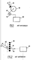
- the second known family relates to automatic return systems of electromechanical direction change indicator (see Figure 1).
- Typical systems of this second family include an angle sensor 10 for detecting and analyzing by means of an electronic module 20 a rotation of a steering wheel 30 connected to a steering shaft 35 when a driver has requested a control means 40 mechanical capable of being guided to left or right and to command an indication of change of direction appropriate.
- the direction change indication control is made possible by a set of transducers sensitive to the displacement of the means 40.
- FIG. 2 shows a control means 40 rotated in a clockwise direction to an intermediate position corresponding to sensitization of the transducer 51.
- This situation corresponds to a particular power supply of change of direction to the right.
- a signal 60 is transmitted to the electronic management unit which will analyze it and control appropriate actions, such as lighting a right turn signal.
- the angle sensor 10 detects the rotation of the steering wheel and transmits information to the electronic module so that it can possibly interrupt said indication power supply. change of direction.
- the angle sensor that generates, depending on the case, information on the relative or absolute position of the steering wheel.
- This information is processed by the management module to determine as relevant as possible whether, in their opinion, the change of direction indication command should be canceled.
- the solutions proposed at present tend to increase the number of sensors in order to provide the electronic management module with a greater quantity of information.
- these sensors provide information on the direction of rotation of the steering wheel and also on its angular position.
- the senor must nevertheless be able to provide sufficiently relevant information to the management module to accurately determine an occurrence of an interruption event of the change of direction indicator.
- the present invention provides an advanced direction change indicator system that overcomes all the aforementioned drawbacks while ensuring good performance.
- the present invention proposes a system for automatically returning a direction change indicator associated with a steering wheel, comprising a displacement guided crew for alternately controlling a feed of the left or right direction change indicators in a route mode. and / or motorway, an electronic module for managing said commands intended in particular to interrupting the increase of the direction change indicators when a required event is detected, a steering wheel rotation detection means capable of supplying the required event to the management module, characterized in that this detection means comprises at least one disk provided on one side with a conductive material and at least two conductive members facing, and in local contact with said face, so that, during a rotation of the flywheel, these bodies and said material can come into contact and in that the at least one face of the disc and the conductive material extend in a plane perpendicular to the axis of rotation of the flywheel.
- the present invention offers many advantages.
- the invention even provides to integrate this detection means or the entire system in the steering wheel itself.
- Another advantage of the system of the invention is that it is particularly reliable and resistant to wear.
- the contact forces between the conductive members and the disk are substantially constant during a rotation of the steering wheel.
- micro-shocks can exist when said members and the conductive material meet during a rotation of the steering wheel, they remain nonetheless negulgeables, which limits the corrosion of these organs and this conductive material.
- FIG. 3 it is possible to visualize a crew 100 with impulse type control. guided displacement and means 101 for detecting rotation of a flywheel 102, of the angle sensor type.
- This figure also shows a possible assembly of these three elements 1 00, 101 and 102.
- the crew 100 has an element 103, such as a control lever, supposed to be biased at one of the longitudinal ends 104 by a conductor and thus pivot at an angle about an axis OO '.
- element 103 such as a control lever
- a module 105 for detecting angular position is also provided.
- this module 105 comprises five separate contacts 106-110 arranged next to one another on a periphery of a portion of an imaginary circle whose central axis is the pivot axis OO 'of the element 103.
- Each of these contacts therefore makes it possible to detect a determined angular position of the element 103.
- central contact 110 for detecting an angle of zero degrees, that is to say a rest position 110 of the element 103 for which it is not solicited. and two contacts 106, 107 and 108, 109 for detecting two distinct angular positions on either side of the rest position 110.
- a signal is generated to control a supply of a change of direction indicator.
- the contacts 107 and 108 closest to the central contact 110 correspond to the supply of a left and right direction change indicator respectively in so-called highway mode.
- This function is active as long as element 103 is held in position 107 or 108 as the case may be.
- the solicitation of the contact 107 generates a succession of ignitions of the right turn signal (three ignitions for example).
- Such a supply is controlled when the contacts 106 and 109, located respectively at the ends of said portion of the imaginary circle, are biased during the pivoting of the element 103 around the axis OO '.
- a power control signal 111 of a suitable direction indicator is generated.
- This signal 111 is transmitted, on the one hand, to one of the turn signals 113 to turn it on and on the other hand, to a management module 112; typically an analog or digital electronic circuit (FPGA, discrete components, DSP, etc.), which manages the interruption of this change of direction indicator supply by means, in particular, of the rotation detection means 101.
- a management module 112 typically an analog or digital electronic circuit (FPGA, discrete components, DSP, etc.), which manages the interruption of this change of direction indicator supply by means, in particular, of the rotation detection means 101.
- this means 101 is schematically in accordance with the representation in FIG.
- It comprises a disk 120 fixed with respect to the steering wheel, the faces of which extend in a plane perpendicular to the axis of rotation PP 'of the steering wheel 102.
- One side of the disc 120 is provided, in part only, with a conductive material 122, 123 so as to define two separate electric tracks 122, 123.
- These two tracks 122 and 123 are arranged radially with respect to the axis of the disc 120 and are each of rectangular shape, substantially longitudinally arcuate, such that they finally have a substantially concave shape with respect to the axis PP 'of rotation of the disc 120 or the steering wheel 102.
- the track 122 has a first portion vis-à-vis the track 123 and a second portion devoid of vis-à-vis.
- the detection means further comprises two conductive members 124, 125 disposed facing the faces of the disc 120, 121 which has the tracks 122, 123.
- these members 124,125 take place under the steering wheel and preferentially still in it, so as to have a set the most integrated and the least bulky possible in the direction of the axis PP ' .
- organs 124, 125 can have different shapes. It is important to prefer those that prefer, still, a small footprint along the axis PP '.
- the conductive members 124, 125 may be metal blade-shaped scrapers 128, 127 as shown in FIG. 4.
- These blades 124,125 are substantially flat in order to limit the size.
- the contact area between a track 122, 123 and a corresponding blade 124, 125 is. It also relatively low, which gives the detection means 101 a good angular position detection accuracy.
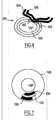
- the rotation detection means 101 also comprises a disc 130 (see FIGS. 5 and 6), one face of which extends in a plane perpendicular to the axis of rotation PP ' of the steering wheel so as to take the least possible space in the direction of the axis PP '
- the conductive members 131-133 are no longer integral with the steering wheel 102.
- the conductive material on the face of this disc has a shape that makes it possible to define at least two electrical tracks, in contact, arranged radially with respect to the axis PP ', each associated with conductive members and angularly offset one of the 'other.
- the disk is provided with two tracks 134 and 136 and a common track 135, these three tracks being in contact and associated with the three conductive strips 131, 133 and 132 respectively.
- the track 135 is preferably of circular shape around the axis PP 'of rotation of the disk 130, and the two tracks 134 and 136 are, each as in the first embodiment, rectangular in shape, substantially arcuate longitudinally, so that they finally have a substantially concave shape with respect to the axis PP 'of rotation of the disk 120 or the wheel 102.
- the track 134 is a central track, in the sense that it is located radially between two tracks 134 and 136.
- this central track 134 is connected to a ground of the circuit as soon as it comes into contact with its associated blade 132, so that a current is able to pass between the central blade 132 and the adjacent blade (with the blades) ( s) 131 and / or 133 when this (these) last (s) is (are) in contact with the corresponding track 134 and / or 136 respectively.
- This second preferred embodiment therefore also allows to integrate very easily around the steering wheel.
- this detection means 101 in the direction of the axis PP 'being very small, it can be easily inserted under the wheel 102 along said axis.
- FIG. 6 shows in this regard a nonlimiting example of possible integration of such means 101 into a housing 140 also accommodating the lever 103 guided to move about the axis OO '.
- the disk 130 is integral with the steering wheel (not shown) and the slats 131-133 are fixed to an element 141, itself secured to the housing 140 which is located under the steering wheel 102.
- the proposed automatic return system integrates well, especially in the housing already planned to accommodate the crew 100.
- the disc 130 is no longer at a distance from the steering wheel beneath it.
- a mold is hollowed into the material which constitutes the flywheel (this material is typically hard plastic), said mold having a shape complementary to that of the disk 102.
- the latter is recessed taking care to leave the face provided with electric tracks air lle, so that the conductive members can come into contact with them,
- this detection means 101 Moreover, he will recognize other possible embodiments of this detection means 101.
- Figures 5 and 6 show a variant in which the disc 130 is provided with a conductive material defining five tracks: a central track 135 and two sets of two tracks 134 and 136, these two sets being diametrically opposed around the disc .
- This variant makes it possible, for example, to increase the occurrences of detection of the direction of rotation of the steering wheel.
- Another alternative may be to delete the central track 135 out of possible contact areas with adjacent tracks 134 and 136.
- Figure 7 schematically shows a disk according to such a variant.
- Yet another obvious variant is to use a disk whose track portions 134 and 136 coincide with the inner and outer edges respectively of the disk 130.
- Another possible obvious variant consists in reversing the operations of each of the two embodiments proposed above.
- the appropriate flashing light is turned on and the management module 112 receiving the signal 111 takes into account the information provided by the rotation detection means 101 of the steering wheel to determine whether to interrupt said supply.
- FIGS. 8A-8F illustrate a nonlimiting example of a situation where the element 103 is pivotally biased such that a right direction indicator feed control in the road mode is activated.
- FIG. 8A illustrates the beginning of this example.
- the crew 100 is not yet solicited by the driver.
- the turn signals are not lit (double arrow 150 white) and the information from the rotation detection means 101 are not analyzed by the electronic management module 112 (indicated by a cross in the double arrow blançhe).
- the detection means 101 supplies the electronic management module 112 with an appropriate electrical signal 115, for example a logic level 1 of the analog A.
- the management module 112 updates certain variables to memorize and analyze at the desired time the movements of the rotation detection means 101.
- the management module 112. uses two variables B and X. the first assigned to 1 when one of the contacts 106 or 109 of the crew 100. relating to the road mode, is fed, the second assigned to 1 when the information from the medium rotational detection 101 are being analyzed by the management module 112.
- the central contact 110 being fed, B is equal to 0 and it follows that, since the information coming from the rotation detecting means 101 is not to be analyzed by the management module 112, the variable X is also equal to 0.
- the contact 109 relating to the road mode, is powered, a signal 111 activates the turn signals 113 (double arrow 150 black) and the management module begins to analyze the information from the rotation detection means 101 (X equal to 1).
- variable B is equal to 1 since one of the contacts relating to the road mode is currently activated.
- the management module 112 uses two new variables S1 and S2, plus a flag denoted NPC.
- S1 and S2 respectively indicate whether the tracks 122 and 123 are in contact with their respective conductive member 124, 125.
- the management module 112 assigns a value 1 to the corresponding variable S 1.
- S1 and S2 are equal to 1 since the contacts are established on tracks 122 and 123.
- the NPC flag indicates whether the two conductive members 124, 125 have ceased to be in contact with their respective track 122, 123 since the variable X is equal to 1, that is to say since the management module 112 has begun. said analysis.
- the NPC flag is active since the two members 124, 125 are in contact with the tracks 122, 123.
- the management module 112 informed by a signal 111, assigns the value 0 to the variable 8, the other variables remaining unchanged.
- Figure 8D shows, a moment later still, that the driver turning the steering wheel, urges the members 124, 125 in rotation in the opposite direction of the clockwise.
- the rotation detecting means continuously providing information on the state of the contacts indicates this change to the management module 112 through a signal 115.
- management module 112 accordingly assigns the null value to the variables S1 and S2, and disables the NPC flag.
- the conduction members 124, 125 are close to the respective tracks 122, 123 and it is the member 124 that first comes into contact with the track 122.
- the management module assigns the value 1 to the variable S1.
- the management module 112 then considers that the change of direction indication supply must not be interrupted yet.
- variable S2 is not yet equal to 1, which indicates that, despite a return of the steering wheel, it has not yet found a position close to the initial position (that of Figure 8A).
- the management module 112 assigns a new value 1 to the variable S1, so that we find our in the situation described in Figure 8D.
- the management module therefore assigns the value 0 to the variable S2.
- Such an event is then recognized by the electronic management module 112 as a power interruption control of the change of direction indicators.
- the turn signals receive from the electronic management module 112 a power interruption control signal 160 (double white arrow).
- variable X is initialized to 0.
- the rotational movements of the detection means 101 are therefore no longer analyzed by the electronic management module 112 (shown in the drawing with a double arrow provided with a cross).
- the detection means 101 and the electronic management module 112 are such that their cooperation is simple and effective.
- the driver could turn the steering wheel counterclockwise at such an angle that it is the member 125 which first comes into contact with the associated track 123.
- FIG. 9A Such a situation is illustrated in FIG. 9A where the arrow 200 indicates the path made by the driving members from the initial position, marked I.
- the management module recognizing that a complete revolution of the steering wheel has been carried out, uses another variable NBT which indicates the number of revolutions performed by the rotational detection means 101.
- the management module 112 increments the NBT variable (value 1 for a lap, etc. ).
- the management module then continues analyzing the information provided by the rotation detecting means 101.
- the detection module decrements NBT as soon as the variable S2 goes from second to zero and we find sacred in the situation described in FIG. 8D.
- Another particular situation not discussed so far corresponds to a situation where the driver requests the rotating crew to control a direction indication supply in road mode while the steering wheel has already been rotated at an angle such that the Conductors are no longer in contact with their respective track.
- the module when the variable B is initialized to 1, the module immediately assigns the value 0 to S1 and S2, 1 to X and deactivates NPC.
- one skilled in the art may alternatively adjust the angular offset between tracks 122 and 123 in the first embodiment, or 134, 136 in the second embodiment, depending on the desired tolerance vis-à-vis -visable errors of interpretation on a detection of an event controlling a power interruption of the indicators of change of direction in road mode.
- wireless communication technologies is an obvious variant of the means envisaged by the invention for transmitting in particular information between the management module 112 and the rotation detection means 101 or the equlpage 100 capable of being guided by movement or flashing lights 113.
Abstract
Description
La présente invention concerne un système de retour automatique d'indicateur de changement de direction dans un véhicule. notamment dans une automobile.The present invention relates to a system for automatically returning a direction indicator in a vehicle. especially in an automobile.
De nombreux systèmes de ce type ont déjà été proposés à l'heure actuelle.Many such systems have already been proposed at this time.
On peut généralement distinguer deux familles dans ces systèmes.We can usually distinguish two families in these systems.
La premiere famille connue concerne des systèmes de retour automatique d'indicateur de changement de direction entièrement mécanique.The first known family relates to fully mechanical automatic return indicator return systems.
Bien qu'ayant rendu de nombreux services, ils comportent un certain nombre de limitations connues : complexité du dispositif, de fonctionnement intégration dans le véhicule et adaptation des fonctionnalités.Although having rendered many services, they include a certain number of known limitations: complexity of the device, operation integration in the vehicle and adaptation of the features.
La deuxième famille connue concerne des systèmes de retour automatique d'indicateur de changement de direction électromécanique (voir figure 1).The second known family relates to automatic return systems of electromechanical direction change indicator (see Figure 1).
Des systèmes typiques de cette deuxième famille comportent un capteur d angle 10 pour détecter puis analyser au moyen d'un module électronique 20 une rotation d'un volant 30 relié à un arbre de direction 35 lorsqu'un conducteur a sollicité un moyen de commande 40 mécanique apte a être guidé à déplacement à gauche ou à droite et à commander une indication de changement de direction appropriée.Typical systems of this second family include an
La commande d'indication de changement de direction est rendue possible grâce à un ensemble de transducteurs sensibles au déplacement du moyen 40.The direction change indication control is made possible by a set of transducers sensitive to the displacement of the
A titre d'exemple, la figure 2 montre un moyen de commande 40 déplacé en rotation dans le sens des aiguilles d'une montre jusqu'à une position intermédiaire qui correspond à une sensibilisation du transducteur 51,By way of example, FIG. 2 shows a control means 40 rotated in a clockwise direction to an intermediate position corresponding to sensitization of the
Cette situation correspond à une alimentation particulière de changement de direction vers la droite.This situation corresponds to a particular power supply of change of direction to the right.
Un signal 60 est transmis à l'unité de gestion électronique qui va l'analyser et commander des actions appropriées, tel l'éclairage d'un clignotant droit.A
Lorsque l'utilisateur tourne maintenant le volant dans le sens inverse des aiguilles d'une montre, le capteur d'angle 10 détecte la rotation du volant et transmet une information au module électronique afin que celui-ci puisse éventuellement interrompre ladite alimentation d'indication de changement de direction.When the user now turns the steering wheel counterclockwise, the
En fait, cette interruption n'a lieu que lorsque un événement requis par le module de gestion électronique apparaît.In fact, this interruption occurs only when an event required by the electronic management module appears.
Plus précisément, le capteur d'angle qui génère selon les cas des informations sur la position relative ou absolue du volant.More precisely, the angle sensor that generates, depending on the case, information on the relative or absolute position of the steering wheel.
Ces informations sont traitées par le module de gestion pour déterminer de manière aussi pertinente que possible si, selon elles, il convient d'annuler la commande d'indication de changement de direction.This information is processed by the management module to determine as relevant as possible whether, in their opinion, the change of direction indication command should be canceled.
Une bonne performance de cette fonction d'annulation repose donc sur une réalisation d'un capteur d'angle efficace et précis accompagné d'un système de traitement en parfaite adéquation avec ce capteur.A good performance of this cancellation function is therefore based on a realization of an effective and precise angle sensor accompanied by a treatment system in perfect adequacy with this sensor.
Les solutions proposées à l'heure actuelle tendent à multiplier le nombre de capteurs afin de fournir au module de gestion électronique une plus grande quantité d'lnformations.The solutions proposed at present tend to increase the number of sensors in order to provide the electronic management module with a greater quantity of information.
A titre d'exemple ces capteurs foumissent des informations sur le sens de rotation du volant et également sur sa position angulaire.By way of example, these sensors provide information on the direction of rotation of the steering wheel and also on its angular position.
Ces solutions ont toutefois des inconvénients non négligeables tels que le coût du système et une difficile intégration de celui-ci aux environs du volant, du fait notamment d'un certain encombrement des capteurs.These solutions, however, have significant disadvantages such as the cost of the system and a difficult integration thereof in the vicinity of the steering wheel, in particular due to a certain size of the sensors.
Ce dernier point prend d'ailleurs toute son impqrtance quand on sait qu'il est de plus en plus envisagé, grâce à l'avancement des technologies dans le domaine notamment automobile, de supprimer l'arbre de direction sur lequel se trouvent lesdits capteurs d'angles.This last point takes all its force when we know that it is more and more envisaged, thanks to the advancement of technologies in the automotive field, to remove the steering shaft on which these sensors are located. angles.
Une telle modification conduit en effet à devoir rapprocher autant que possible ces capteurs d'angle du volant, ce qui n'est pas exempt de difficulté puisque, comme évoqué précédemment, ces capteurs restent encombrants.Such a change in fact leads to having to bring as close as possible these angle sensors of the steering wheel, which is not free of difficulty since, as mentioned above, these sensors remain bulky.
Afin de répondre à un tel problème, certaines améliorations connues ont permis de réduire le nombre de capteurs et de simplifier leur structure, rendant ainsi possible une intégration d'un système d'indicateur de changement de direction comprenant ces capteurs dans des systèmes de direction dépourvus d'arbre de direction.In order to respond to such a problem, certain known improvements have made it possible to reduce the number of sensors and to simplify their structure, thus making it possible to integrate a change of direction indicator system comprising these sensors in steering systems without steering shaft.
Cependant, ces systèmes, et notamment les capteurs d'angles qu'ils utilisent nécessitent encore d'être améliorés.However, these systems, including the angle sensors they use still need to be improved.
En particulier, il est important de poursuivre notamment la réduction de l'encombrement des capteurs.In particular, it is important to continue in particular to reduce the size of the sensors.
Mais ceci ne doit absolument pas se faire au détriment d'une bonne coopération du capteur avec le module électronique de gestion.But this must absolutely not be at the expense of good cooperation of the sensor with the electronic management module.
En d'autres termes, le capteur doit être néanmoins capable de fournir une information suffisamment pertinente au module de gestion pour déterminer précisément une occurrence d'un événement d'interruption des indicateur de changement de direction.In other words, the sensor must nevertheless be able to provide sufficiently relevant information to the management module to accurately determine an occurrence of an interruption event of the change of direction indicator.
Ainsi la présente invention propose un système d'indicateur de changement de direction évolué qui permet de s'affranchir de l'ensemble des inconvénients précités tout en garantissant de bonnes performances.Thus the present invention provides an advanced direction change indicator system that overcomes all the aforementioned drawbacks while ensuring good performance.
Elle propose en particulier un système d'indicateur de changement de direction où coopèrent un module de gestion électronique, un équipage à commande de type impulsionnel et un capteur d'angle extrêmement plat en comparaison à l'état de la technique.In particular, it proposes a change of direction indicator system in which an electronic management module, a pulse-type control unit and an extremely flat angle sensor cooperate in comparison with the state of the art.
Plus précisément encore, la présente invention propose un système de retour automatique d'indicateur de changement de direction associé à un volant, comprenant un équipage guidé à déplacement pour commander alternativement une alimentation des indicateurs de changement de direction gauche ou droit dans un mode de route et/ou autoroute, un module électronique de gestion desdites commandes destiné notamment à interrompre l'allmentation des indicateurs de changement de direction quand un événement requis est détecté, un moyen de détection de rotation du volant apte à fournir l'événement requis au module de gestion, caractérisé en ce que ce moyen de détection comporte au moins un disque muni sur une face d'un matériau conducteur et d'au moins deux organes conducteurs en regard de, et en contact local avec ladite face, de sorte que, lors d'une rotation du volant, ces organes et ledit matériau peuvent entrer en contact, et en ce que la face du disque au moins prévu ainsi que le matériau conducteur s'étenden dans un plan perpendiculaire à l'axe de rotation du volant.More precisely still, the present invention proposes a system for automatically returning a direction change indicator associated with a steering wheel, comprising a displacement guided crew for alternately controlling a feed of the left or right direction change indicators in a route mode. and / or motorway, an electronic module for managing said commands intended in particular to interrupting the increase of the direction change indicators when a required event is detected, a steering wheel rotation detection means capable of supplying the required event to the management module, characterized in that this detection means comprises at least one disk provided on one side with a conductive material and at least two conductive members facing, and in local contact with said face, so that, during a rotation of the flywheel, these bodies and said material can come into contact and in that the at least one face of the disc and the conductive material extend in a plane perpendicular to the axis of rotation of the flywheel.
Des aspects préférés, mais non limitatifs de ce système de retour automatique d'indicateur de changement de direction, associé à un volant selon la présente invention, sont les suivants :
- les organes conducteurs sont agencés de telle sorte qu'ils sont en contact local pennanent avec le disque au moins prévu,
- le matériau conducteur définit des pistes électriques disposées radialement par rapport à l'axe du disque.
- le matériau conducteur définit des pistes électriques rectangulaires sensiblement arquées longitudinaiement de telle manière qu'elles aient une forme sensiblement concave par rapport à l'axe de rotation du volant,
- les organes sont disposés le long de l'axe radial du disque de telle manière que lors d'une rotation du volant, chacun d'eux peut entrer en contact avec une piste correspondante,
- il comporte un disque muni d'un matériau conducteur formant au moins deux portions de couronne électrique décalées anguiairement qui définissent un ensemble de deux pistes électriques et en ce que chacun des deux organes au moins prévu est agencé de telle manière qu'il peut entrer en contact avec l'une des deux pistes électriques au moins prévue, de sorte que, notamment, un sens de rotation du volant est détecté selon que l'un ou l'autre des organes entre en premier en contact avec sa piste correspondante,
- le matériau conducteur définit en outre une troisième piste électrique en forme de couronne sur la face du disque,
- la troisième piste et les deux portions de pistes au moins prévues sont en contact,
- une portion de la troisième piste se trouve entre les deux autres pistes,
- il comporte trois organes conducteurs disposés radialement par rapport à l'axe du disque, chacun des trois organes étant respectivement associé à une des trois pistes électriques,
- l'orgiane conducteur associé à la troisième piste est connecté à une masse électrique,
- les organes conducteurs sont fixes et le disque est sollicité en rotation par le volant,
- le disque est Intégré au volant,
- outre la troisième piste, le disque est muni de quatre portions de couronne électrique qui définissent quatre pistes électriques, celles-ci étant décalées deux à deux angulairement et disposées deux à deux de façon diamétralement opposée autour du disque,
- il comporte au moins deux pistes distinctes décalées angulairement et disposées radialement par rapport à l'axe du disque et au moins deux organes conducteurs associés respectivement aux deux pistes, ces organes étant disposés en regard de la face du disque de sorte qu'ils puissent entrer en contact avec la piste correspondante lors d'une rotation du volant,
- les disques sont fixes et les organes conducteurs sont sollicités en rotation par le volant,
- les disques sont intégrés au volant,
- les organes conducteurs sont des frotteurs,
- les organes conducteurs sont des lames métalliques courbées.
- the conductive members are arranged such that they are in permanent local contact with the at least one disc,
- the conductive material defines electrical tracks arranged radially with respect to the axis of the disc.
- the conductive material defines rectangular electrical tracks substantially arcuate longitudinally so that they have a substantially concave shape with respect to the axis of rotation of the flywheel,
- the members are arranged along the radial axis of the disc such that during a rotation of the steering wheel, each of them can come into contact with a corresponding track,
- it comprises a disc provided with a conductive material forming at least two angularly offset electric crown portions which define a set of two electrical tracks and in that each of the at least two members is arranged in such a way that it can enter contact with at least one of the two electrical tracks, so that, in particular, a direction of rotation of the steering wheel is detected according to that one or the other of the organs comes first in contact with its corresponding track,
- the conductive material further defines a third crown-shaped electric track on the face of the disc,
- the third track and the two portions of tracks at least provided are in contact,
- a portion of the third runway is between the two other runways,
- it comprises three conductive members arranged radially with respect to the axis of the disc, each of the three members being respectively associated with one of the three electrical tracks,
- the orgian conductor associated with the third track is connected to an electrical ground,
- the conductive members are fixed and the disc is urged to rotate by the steering wheel,
- the disc is Integrated at the wheel,
- in addition to the third track, the disk is provided with four portions of electric crown which define four electric tracks, the latter being offset two by two angularly and arranged two by two diametrically opposite around the disk,
- it comprises at least two distinct tracks angularly offset and arranged radially relative to the axis of the disc and at least two conductive members respectively associated with the two tracks, these members being arranged facing the face of the disc so that they can enter in contact with the corresponding track during a rotation of the steering wheel,
- the disks are fixed and the conductive members are urged in rotation by the steering wheel,
- the discs are integrated in the steering wheel,
- the conductive members are rubbers,
- the conductive members are curved metal blades.
Ainsi, la présente invention offre de nombreux avantages.Thus, the present invention offers many advantages.
Notamment, on profite avantageusement de l'intégration dans ce type de système d'un moyen de détection de rotation particulièrement peu épais dans la direction de l'axe de rotation du volant et donc particulièrement adapté pour être positionné sans difficulté très proche du volant.In particular, it advantageously benefits from the integration in this type of system a rotation detection means particularly thin in the direction of the axis of rotation of the steering wheel and therefore particularly suitable to be positioned without difficulty very close to the steering wheel.
A ce titre, l'invention prévoit même d'intégrer ce moyen de détection, voire l'ensemble du système, dans le volant lui-même.As such, the invention even provides to integrate this detection means or the entire system in the steering wheel itself.
Les montages dans la chaîne de fabrication sont ainsi simplifiés et on réalise dans le même temps un volant doté de fonctions intelligentes.The assemblies in the production line are thus simplified and at the same time a steering wheel with intelligent functions is produced.
Un autre avantage du système de l'invention veut qu'il soit particulièrement fiable et résistant à l'usure.Another advantage of the system of the invention is that it is particularly reliable and resistant to wear.
En particulier, dans le moyen de détection de rotation proposé, les forces de contact mises en jeu entre les organes conducteurs et le disque sont sensiblement constantes au cours d'une rotation du volant.In particular, in the proposed rotation detecting means, the contact forces between the conductive members and the disk are substantially constant during a rotation of the steering wheel.
Ainsi, si des microchocs peuvent exister lorsque lesdits organes et le matériau conducteur se rencontrent au cours d'une rotation du volant, ceux-ci n'en demeurent pas moins négllgeables, ce qui limite la corrosion de ces organes et de ce matériau conducteur.Thus, if micro-shocks can exist when said members and the conductive material meet during a rotation of the steering wheel, they remain nonetheless negulgeables, which limits the corrosion of these organs and this conductive material.
D'autres aspects, buts et avantages de la présente invention apparaîtront mieux à la lecture de la description détaillée suivante d'une forme de réalisation préférée de celle-ci, donnée à titre d'exemple non limitatif et faite en référence aux dessins annexés, sur lesquels :
- la figure 1 illustre schématiquement et en partie un système de d'indicateur de changement de direction électromécanique de l'état de l'art,
- la figure 2 montre schématiquement un moyen de commande 40 associé à des transducteurs et communiquant à une unité de gestion électronique une information sur sa position,
- la figure 3 montre un système d'indicateur de changement de direction selon la présente invention, ainsi qu'un assemblage possible de ce système aux environs d'un volant,
- la figure 4 représente un premier mode de réalisation d'un moyen de détection de rotation utilisé dans le système selon l'invention,
- la figure 5 représente un deuxième mode de réalisation d'un moyen de détection de rotation utilisé dans le système selon l'invention,
- la figure 6 montre, à titre illustratif et de façon non limitative, une intégration possible du deuxième moyen de détection de rotation, proposé notamment figure 5, dans un boitier accueillant également un équipage guidé à déplacement autour d'un de rotation,
- la figure 7 montre une variante possible de réalisation du deuxième moyen de détection de rotation proposé notamment figure 5 et utilisé avantageusement dans le système selon l'invention,
- les figures 8 illustrent un exemple de fonctionnement du système selon l'invention utilisant le premier moyen de détection de rotation du volant,
- les figures 9 servent d'illustration à une description d'une situation particulière pouvant être rencontrée lors du fonctionnement du système selon l'invention,
- FIG. 1 schematically and partially illustrates an electromechanical change of direction indicator system of the state of the art,
- FIG. 2 schematically shows control means 40 associated with transducers and communicating to an electronic management unit information on its position,
- FIG. 3 shows a change of direction indicator system according to the present invention, as well as a possible assembly of this system in the vicinity of a steering wheel,
- FIG. 4 represents a first embodiment of a rotation detection means used in the system according to the invention,
- FIG. 5 represents a second embodiment of a rotation detection means used in the system according to the invention,
- FIG. 6 shows, by way of illustration and in a nonlimiting manner, a possible integration of the second rotation detection means, proposed in particular in FIG. 5, in a housing also accommodating a guided crew moving around a rotation,
- FIG. 7 shows a possible variant embodiment of the second proposed rotation detection means, in particular FIG. 5 and advantageously used in the system according to the invention,
- FIG. 8 illustrates an example of operation of the system according to the invention using the first steering wheel rotation detection means,
- FIGS. 9 serve to illustrate a description of a particular situation that may be encountered during operation of the system according to the invention,
En se référant maintenant à la figure 3, on peut visualiser un équipage 100 à commande de type impulsionnel. guidé à déplacement et un moyen de détection 101 de rotation d'un volant 102, du type capteur d'angle.Referring now to FIG. 3, it is possible to visualize a
Cette figure montre en outre un assemblage possible de ces trois éléments 1 00, 101 et 102.This figure also shows a possible assembly of these three
L'équipage 100 possède un élément 103, tel un levier de commande, censé être sollicité à une des extrémités longitudinales 104 par un conducteur et pivoter ainsi selon un certain angle autour d'un axe OO'.The
Par ailleurs, on trouve à l'extrémité distale du point de sollicitation un module 105 de détection de position angulaire.Furthermore, at the distal end of the biasing point, there is a
Selon un aspect préféré de l'invention, ce module 105 comporte cinq contacts distincts 106-110 disposés les uns à coté des autres sur une périphérie d'une portion d'un cercle imaginaire dont un axe central est l'axe de pivotement OO' de l'élément 103.According to a preferred aspect of the invention, this
Chacun de ces contacts permettent donc de détecter une position angulaire déterminée de l'élément 103.Each of these contacts therefore makes it possible to detect a determined angular position of the
En particulier, on dispose d'un contact central 110 pour détecter un angle de zéro degré, c'est-à-dire une position de repos 110 de l'élément 103 pour laquelle il n'est pas solicité. et de deux contacts 106, 107 et 108,109 pour détecter deux positions angulaires distinctes de part et d'autre de la position de repos 110.In particular, there is a
Dès qu'une position angulaire prévue est détectée lors d'une alimentation de l'un quelconque de ces quatre contacts, un signal est généré pour commander une alimentation d'un indicateur de changement de direction.As soon as a predicted angular position is detected during a supply of any of these four contacts, a signal is generated to control a supply of a change of direction indicator.
En particulier, les contacts 107 et 108 les plus proches du contact central 110 correspondent à l'alimentation d'un indicateur de changement de direction gauche et droit respectivement en mode dit autoroute.In particular, the
Cette fonction est active tant que l'élément 103 est maintenu en position 107 ou 108 selon le cas.This function is active as long as
En effet lorsque le conducteur ne sollicite plus cet élément 103, celui-ci revient automatiquement en position de repos 110 initiale et l'alimentation de l'indicateur de changement de direction s'interrompt ainsi aussitôt.Indeed, when the driver no longer solicits this
Si une telle alimentation en mode autoroute correspond à ainsi allumer un clignotant tant que l'élément 103 est maintenu en position 107 ou 108, l'invention n'exclut pas de prévoir tout autre type d'alimentation des clignotants.If such a power supply in highway mode is thus turn on a flashing as the
A titre d'exempte, on peut prévoir que la sollicitation du contact 107 génère un succession d'allumages du clignotant droit (trois allumages par exemple).For example, it can be provided that the solicitation of the
Ainsi, tant que l'élément 103 est maintenu en position 108, le clignotant droit est allumé et lorsqu'il est relâché, la dernière commande d'indication de changement de direction droit est prise en compte, ce qul génère une dernière succession d'allumages du clignotant en quaistion.Thus, as long as the
Bien entendu, l'homme du métier reconnaitra ici diverses variantes possibles à cette forme de réalisation.Of course, one skilled in the art will recognize here various possible variants to this embodiment.
Dans tous les cas, comme on l'aura compris, dans le mode autoroute de la présente invention, on ne prend pas en compte la sollicitation en rotation du volant 102, à l'aide du moyen de détection de rotation 101, pour interrompre une alimentation d'indicateur de changement de direction.In all cases, as will be understood, in the highway mode of the present invention, it does not take into account the urging of rotation of the
Ceci n'est pas le cas en revanche pour ce qui concerne une alimentation en mode route.This is not the case, however, with regard to a power supply in road mode.
Une telle alimentation est commandée lorsque les contacts 106 et 109, situés respectivement aux extrémités de ladite portion du cercle imaginaire, sont sollicités lors du pivotement de l'élément 103 autour de l'axe OO'.Such a supply is controlled when the
Dès que l'un de ces contacts 106,109 est alimenté, un signal 111 de commande d'alimentation d'un indicateur de changement de direction approprié est généré.As soon as one of these
Ce signal 111 est transmis, d'une part, à l'un des clignotants 113 pour l'allumer et, d'autre part, à un module de gestion 112,; typiquement un circuit électronique analogique ou numérique (FPGA, composants discrets. DSP, etc....), qui gère l'interruption de cette alimentation d'indicateur de changement de direction au moyen, notamment, du moyen de détection de rotation 101.This
Afin de comprendre plus en détails le fonctionnement du système en mode route, on va maintenant décrire le moyen de détection de rotation 101 du volant 102.In order to understand in more detail the operation of the system in road mode, the rotation detection means 101 of the
Dans un premier mode de réalisation de l'invention, ce moyen 101 est schématiquement conforme à la représentation sur la figure 3.In a first embodiment of the invention, this means 101 is schematically in accordance with the representation in FIG.
Il comporte un disque 120, fixe par rapport au volant, dont les faces s'étendent dans un plan perpendiculaire à l'axe de rotation PP' du volant 102.It comprises a
Une face du disque 120 est munie, en partie seulement, d'un matériau conducteur 122,123 de manière à définir deux pistes électriques 122,123 distinctes.One side of the
Ces deux pistes 122 et 123 sont disposées radialement par rapport à l'axe du disque 120 et sont chacune de forme rectangulaire, sensiblement arquées longitudinalement, de telle sorte qu'elles aient finalement une forme sensiblement concave par rapport à l'axe PP' de rotation du disque 120 ou du volant 102.These two
Par ailleurs, elles sont agencées sur la face du disque de telle sorte qu'il existe entre elles un décalage angulaire autour de l'axe PP'.Furthermore, they are arranged on the face of the disk so that there is between them an angular offset around the axis PP '.
Ainsi, à titre d'exemple, la piste 122 possède une première partie en vis-â-vis avec la piste 123 et une seconde partie dépourvue de vis-à-vis.Thus, for example, the
Le moyen de détection comporte en outre deux organes conducteurs 124,125 disposés en regard des faces du disque 120,121 qui possède les pistes 122, 123.The detection means further comprises two
Ces organes 124, 125 sont donc disposés radialement rapport à l'axe PP' du disque.These
Par ailleurs, ils sont solidaires du volant 102, de sorte qu'ils peuvent entrer en contact avec la piste correspondante 122,123 respectivement lorsqu'ils sont sollicités en pivotement autour de l'axe PP' par le volant 102.Moreover, they are integral with the
Selon un aspect préféré de l'invention, ces organes 124,125 prennent place sous le volant et préférentiellement encore dans celui-ci, de manière à disposer d'un ensemble le plus intégré et le moins encombrant possible dans la direction de l'axe PP'.According to a preferred aspect of the invention, these members 124,125 take place under the steering wheel and preferentially still in it, so as to have a set the most integrated and the least bulky possible in the direction of the axis PP ' .
En outre, si ces organes 124, 125 peuvent posséder différentes formes. il est important de préférer celles qui privilégient, encore, un faible encombrement le long de l'axe PP'.In addition, if these
Ainsi, à titre d'exemple, les organes conducteurs 124, 125 peuvent être des frotteurs 128, 127 en forme de lame métalliques comme représentées sur la figure 4.Thus, by way of example, the
Ces lames 124,125 sont sensiblement plates dans le souci de limiter l'encombrement.These blades 124,125 are substantially flat in order to limit the size.
Elles ont en outre, au moins en partie, une forme convexe par rapport à l'axe PP' de rotation du disque 102 pour venir prendre contact avec la face de ce demier sur une zone locale restreinte,They also have, at least in part, a shape convex relative to the axis PP 'of rotation of the
De cette manière, la surface de contact entre une piste 122,123 et une lame correspondante 124,125 est. elle aussi, relativement faible, ce qui confère au moyen de détection 101 une bonne précision angulaire de détection de position.In this way, the contact area between a
Dans un deuxième mode de réalisation de l'invention, le moyen de détection de rotation 101 comporte aussi un disque 130 (voir les figures 5 et 6), dont une face s'étend dans un plan perpendiculaire à l'axe de rotation PP' du volant de manière à prendre le moins de place possible dans la direction de l'axe PP'In a second embodiment of the invention, the rotation detection means 101 also comprises a disc 130 (see FIGS. 5 and 6), one face of which extends in a plane perpendicular to the axis of rotation PP ' of the steering wheel so as to take the least possible space in the direction of the axis PP '
Cependant, contrairement au premier mode de réalisation décrit plus haut. les organes conducteurs 131-133, préférentiellement de forme identique à ceux utilisés dans le premier mode réalisation, ne sont plus solidaires du volant 102.However, unlike the first embodiment described above. the conductive members 131-133, preferably identical in shape to those used in the first embodiment, are no longer integral with the
Ils sont en effet fixés à un support solidaire de l'habitacle par exemple. tandis que c'est le disque 130 qui est solidaire, par exemple, du volant et qui, ainsi, peut être amené à pivoter autour de l'axe PP'.They are indeed attached to a solidarity support of the cabin for example. while it is the
Le matériau conducteur sur la face de ce disque possède une forme qui permet de définir au moins deux pistes électriques, en contact, disposées radialement par rapport à l'axe PP', associées chacune à des organes conducteurs et décalées angulairement l'une de l'autre.The conductive material on the face of this disc has a shape that makes it possible to define at least two electrical tracks, in contact, arranged radially with respect to the axis PP ', each associated with conductive members and angularly offset one of the 'other.
Par exemple sur la figure 5, le disque est muni de deux pistes 134 et 136 et d'une piste commune 135, ces trois pistes étant en contact et associées aux trois lames conductrices 131, 133 et 132 respectivement.For example in Figure 5, the disk is provided with two
La piste 135 est préférentiellement de forme circulaire autour de l'axe PP' de rotation du disque 130, et les deux pistes 134 et 136 sont, chacune comme dans le premier mode de réalisation, de forme rectangulaire, sensiblement arquée longitudinalement, de telle sorte qu'elles aient finalement une forme sensiblement concave par rapport à l'axe PP' de rotation du disque 120 ou du volant 102.The
On peut voir également que la piste 134 est une piste centrale, au sens où elle se situe radialement entre deux pistes 134 et 136.It can also be seen that the
Typiquement, cette piste centrale 134 est connectée à une masse du circuit dès qu'elle est en contact avec sa lamelle 132 associée, si bien qu'un courant est susceptible de passer entre la lame centrale 132 à la lame (aux lames) adjacente(s) 131 et/ou 133 lorsque cette (ces) demière(s) est (sont) en contact avec la piste correspondante 134 et/ou 136 respectivement.Typically, this
Ce deuxième mode de réalisation préféré permet donc, lui aussi, de s'intégrer très facilement aux environs du volant.This second preferred embodiment therefore also allows to integrate very easily around the steering wheel.
En particulier, l'encombrement de ce moyen de détection 101 dans de le sens de l'axe PP' étant très faible, on peut l'insérer aisément sous le volant 102 le long dudit axe.In particular, the size of this detection means 101 in the direction of the axis PP 'being very small, it can be easily inserted under the
La figure 6 montre à cet égard un exemple, non limitatif, d'intégration possible d'un tel moyen 101 dans un boîtier 140 accueillant également le levier 103 guidé à déplacement autour de l'axe OO'.FIG. 6 shows in this regard a nonlimiting example of possible integration of
Le disque 130 est solidaire du volant (non représenté) et les lamelles 131-133 sont fixées à un élément 141, lui-même solidaire du boîtier 140 qui se trouve sous le volant 102.The
Lorsque le conducteur sollicite ce dernier, le disque est entraîné en rotation.When the driver requests the latter, the disc is rotated.
Et, selon l'angle de cette rotation, les lames 131 et 132 entrent éventuellement en contact avec la piste correspondante 136 et 134 respectivement.And, depending on the angle of this rotation, the
Comme on peut le voir d'après cette figure 6, le système de retour automatique proposé s'intègre bien, notamment dans le boîtier déjà prévu pour accueillir l'équipage 100.As can be seen from this figure 6, the proposed automatic return system integrates well, especially in the housing already planned to accommodate the
Selon un autre aspect de l'invention, le disque 130 n'est plus à une certaine distance du volant sous celui-ci.According to another aspect of the invention, the
II se trouve directement encastré sous le volant lui-même.It is directly embedded under the steering wheel itself.
A cet effet, on creuse un moule dans le matériau qui constitue le volant (ce matériau est typiquement du plastique dur), ledit moule ayant une forme complémentaire à celle du disque 102.For this purpose, a mold is hollowed into the material which constitutes the flywheel (this material is typically hard plastic), said mold having a shape complementary to that of the
En outre, ce demier est encastré en prenant garde de laisser la face munie des pistes électriques à l'air llbre, afin que les organes conducteurs puissent entrer en contact avec elles,In addition, the latter is recessed taking care to leave the face provided with electric tracks air lle, so that the conductive members can come into contact with them,
Une telle disposition permet avantageusement de réduire encore plus l'encombrement lié à ce moyen de détection 101.Such an arrangement advantageously makes it possible to further reduce the size bound to this detection means 101.
Bien entendu l'Homme du métier comprendra que, dans le premier mode de réalisation, ce sont les organes conducteurs que l'on encastre sous le volant 102.Of course, those skilled in the art will understand that, in the first embodiment, it is the conductive members that are recessed under the
Par ailleurs, il reconnaîtra d'autres modes de réalisation possibles de ce moyen de détection 101.Moreover, he will recognize other possible embodiments of this detection means 101.
En particulier, les figures 5 et 6 montrent une variante dans laquelle le disque 130 est muni d'un matériau conducteur définissant cinq pistes : une piste centrale 135 et deux ensembles de deux pistes 134 et 136, ces deux ensembles étant diamétralement opposés autour du disque.In particular, Figures 5 and 6 show a variant in which the
Cette variante permet par exemple d'augmenter les occurrences de détection du sens de rotation du volant.This variant makes it possible, for example, to increase the occurrences of detection of the direction of rotation of the steering wheel.
Une autre variante peut consister à supprimer la piste centrale 135 hors des zones de contact possibles avec les pistes adjacentes 134 et 136.Another alternative may be to delete the
La figure 7 montre schématiquement un disque selon une telle variante.Figure 7 schematically shows a disk according to such a variant.
De c e manière, on réalise notamment des économies sur le matériau conducteur.In this way, particular savings are made on the conductive material.
Une autre variante évidente encore, consiste à utiliser un disque dont les portions de piste 134 et 136 coïncident avec les bords internes et extemss respectivement du disque 130.Yet another obvious variant is to use a disk whose
Une autre variante évidente possible consiste à inverser les fonctionnements de chacun des deux modes de réalisation proposés ci-dessus.Another possible obvious variant consists in reversing the operations of each of the two embodiments proposed above.
En particulier, dans le premier mode de réalisation où les deux pistes sont distinctes, on peut choisir de rendre le disque, plutôt que les organes, solidaire du volant etc.In particular, in the first embodiment where the two tracks are distinct, one can choose to make the disc, rather than the organs, integral with the steering wheel etc.
On va maintenant décrire le fonctionnement du système qui vient d'être décrit lorsqu'une commande d'alimentation d'indicateur de changement de direction en mode route a été activée.We will now describe the operation of the system that has just been described when a direction change indicator power supply control mode has been activated.
Comme évoqué précédemment, une telle commande est activée lorsque l'élément 103 est sollicité en pivotement et qu'ainsi l'un des contacts 106 ou 109 est activé.As mentioned above, such a command is activated when the
A cet instant, le clignotant approprié est allumé et le module de gestion 112 recevant le signal 111 prend en compte les informations fournies par le moyen de détection de rotation 101 du volant pour déterminer s'il convient d'interrompre ladite alimentation.At this time, the appropriate flashing light is turned on and the
A cet égard les figures 8A-8F illustrent un exemple non limitatif de situation où l'élément 103 est sollicité en pivotement de telle manière qu'une commande d'alimentation d'indicateur de changement de direction droit en mode route est activée.In this regard, FIGS. 8A-8F illustrate a nonlimiting example of a situation where the
Sur chacune de ces figures, on peut voir :
- à gauche l'équipage 100 comportant les cinq
contacts 106 à 109, - au centre un symbole en forme de
double flèche 150 pour indiquer, en fond blanc, que les clignotants sont éteints et, en fond noir qu'ils sont allumés, et le moyen de détection derotation 101 selon le premier mode de réalisation proposé ci-dessus, c'est-à-dire muni de deuxpistes 122et 123 distinctes, - à droite, des variables d'état éventuellement utilisées par le module de gestion électronique 112 pour analyser les mouvements de rotation dudit moyen de détection 101.
- on the left the
crew 100 including the fivecontacts 106 to 109, - in the center, a symbol in the form of a
double arrow 150 to indicate, in a white background, that the turn signals are off and, in the dark field, that they are on, and the rotation detection means 101 according to the first embodiment proposed above. above, that is to say provided with twoseparate tracks - on the right, state variables possibly used by the
electronic management module 112 to analyze the rotational movements of said detection means 101.
La fi gure 8A Illustre le début de cet exemple.Figure 8A illustrates the beginning of this example.
L'équipage 100 n'est pas encore sollicité par le conducteur.The
II se trouve donc dans sa position de repos, le contact 110 étant alimenté (en noir).It is therefore in its rest position, the
Bien évidemment, les clignotants ne sont pas allumés (double flèche 150 blanche) et les informations issues du moyen de détection de rotation 101 ne sont pas analysées par le module de gestion électronique 112 (indiqué par une croix dans la double flèche blançhe).Of course, the turn signals are not lit (
Cependent à titre indicatif, on peut voir ici que les organes 124,125, solidaires du volant dans ce mode de réalisation, sont en contact avec leur piste respective 122,123.As an indication, we can see here that the 124,125 bodies, integral steering wheel in this embodiment, are in contact with their respective track 122,123.
Dans ce cas, le moyen de détection 101 fournit au module de gestion électronique 112 un signal électrique 115 approprié, par exemple un niveau logique 1 du analogique A.In this case, the detection means 101 supplies the
De son côté, le module de gestion 112 met à jour certaines variables pour mémoriser et analyser au moment voulu les mouvements du moyen de détection de rotation 101.For its part, the
Par exemple, il utilise deux variables B et X. la première assignée à 1 lorsque l'un des contacts 106 ou 109 de l'équipage 100. relatifs au mode route, est alimenté, la seconde assignée à 1 lorsque les informations issues du moyen de détection de rotation 101 sont en cours d'analyse par le module de gestion 112.For example, it uses two variables B and X. the first assigned to 1 when one of the
Ainsi, sur la figure 8A, le contact central 110 étant alimenté, B est égale à 0 et il en découle que, les informations issues du moyen de détection de rotation 101 n'étant pas à analyser par le module de gestion 112, la variable X est aussi égale à 0.Thus, in FIG. 8A, the
Un instant plus tard, le conducteur sollicite l'équipage 100 en rotation dans le sens des aiguilles d'une montre pour indiquer un changement de direction à droite (figure 8B).A moment later, the driver urges the
Le contact 109, relatif au mode route, est alimenté, un signal 111 active les clignotants 113 (double flèche 150 noire) et le module de gestion commence à analyser les informations issues du moyen de détection de rotation 101 (X égale à 1).The
On notera également, que la variable B est égale à 1 puisque l'un des contacts relatifs au mode route est actuellement activé.Note also that the variable B is equal to 1 since one of the contacts relating to the road mode is currently activated.
En outre, pour analyser les mouvements du moyen de détection de rotation 101, le module de gestion 112 utilise deux nouvelles variables S1 et S2, plus un drapeau noté NPC.In addition, to analyze the movements of the rotation detection means 101, the
A titre d'exemple non limitatif, lorsqu'un contact est effectivement établi sur l'une de ces pistes, le module de gestion 112 assigne une valeur 1 à la variable Si correspondante.As a non-limiting example, when a contact is actually established on one of these tracks, the
Ainsi, sur la figure 8B, S1 et S2 sont égales à 1 puisque les contacts sont établis sur les pistes 122 et 123.Thus, in FIG. 8B, S1 and S2 are equal to 1 since the contacts are established on
Le drapeau NPC indique si les deux organes conducteurs 124,125 ont cessé d'être en contact avec leur piste respective 122, 123 depuis que la variable X est égale à 1, c'est-à-dire depuis que le module de gestion 112 a commence ladite analyse.The NPC flag indicates whether the two
Un tel drapeau est utilisé comme suit :
- actifs lorsque les deux organes conducteurs mentionnés sont toujours en contact avec leur piste correspondante,
- inactif, lorsque les deux organes conducteurs mentionnés ne sont plus en contact avec leur piste correspondante.
- active when the two conductive members mentioned are still in contact with their corresponding track,
- inactive, when the two conductive members mentioned are no longer in contact with their corresponding track.
Ainsi sur la figure 8B, le drapeau NPC est actif puisque les deux organes 124, 125 sont en contact avec les pistes 122, 123.Thus, in FIG. 8B, the NPC flag is active since the two
En se référant maintenant à la figure BC, le conducteur ne sollicite plus l'équipage 100 en rotation.Referring now to Figure BC, the driver no longer solicits the
Ce dernier revient donc automatiquement en position de repos initiale et alimente ainsi le contact central 110.The latter automatically returns to the initial rest position and thus feeds the
Le module de gestion 112, informé par un signal 111, assigne la valeur 0 à la variable 8, les autres variables restant inchangées.The
La figure 8D montre, un instant plus tard encore, que le conducteur toumant le volant, sollicite les organes 124, 125 en rotation dans le sens contraire des aiguilles d'une montre.Figure 8D shows, a moment later still, that the driver turning the steering wheel, urges the
Ces demiers pivotent autour de l'axe PP' selon un angle tel qu'ils cessent d'être en contact avec les pistes 122 et 123.These latter pivot about the axis PP 'at such an angle that they cease to be in contact with the
Le moyen de détection de rotation fournissant continûment une information sur l'état des contacts, indique ce changement au module de gestion 112 au travers d'un signal 115.The rotation detecting means continuously providing information on the state of the contacts indicates this change to the
Et le module de gestion 112 assigne en conséquence la valeur nulle aux variables S1 et S2, et désactive le drapeau NPC.And the
Sur la figure 8E, le conducteur ayant maintenant changé de direction, sollicite le volant en rotation en sens inverse, c'est-à-dire dans le sens des aiguilles d'une montre.In Figure 8E, the driver has now changed direction, urges the steering wheel in rotation in the opposite direction, that is to say in the direction of clockwise.
Les organes de conduction 124,125 se rapprochent des pistes respectives 122,123 et c'est l'organe 124 qul entre en premier en contact avec la piste 122.The
De ce fait, le module de gestion assigne la valeur 1 à la variable S1.As a result, the management module assigns the
Plus généralement, J'état des variables à cet instant est donc le suivant :
Le module de gestion 112 considère alors que l'alimentation d'indication de changement de direction ne doit pas encore être interrompue.The
En effet, la variable S2 n'est pas encore égale à 1, ce qui indique que, malgré un retour du volant, celui-ci n'a pas encore retrouvé une position proche de la position initiale (celle de la figure 8A).Indeed, the variable S2 is not yet equal to 1, which indicates that, despite a return of the steering wheel, it has not yet found a position close to the initial position (that of Figure 8A).
Ainsi, si l'on suppose que le volant est de nouveau sollicité dans le sens contraire des aiguilles d'une montre selon un angle tel que l'organe 124 cesse de nouveau d'être en contact avec la piste 122, le module de gestion 112 assigne une nouvelle valeur 1 à la variable S1, de sorte que l'on se retrouve dans la situation décrite dans la figure 8D.Thus, if it is assumed that the steering wheel is again biased counterclockwise at an angle such that the
Au contraire, en se référant à la figure 8F, si le conducteur continue à tourner le volant dans le sens des aiguilles d'une montre, l'organe 125 finit, lui aussi, par entrer en contact avec la piste 123, correspondant ainsi à un retour du volant dans une position proche de la position initiale illustrée sur les figures 8A et 8B.On the contrary, with reference to FIG. 8F, if the driver continues to turn the steering wheel clockwise, the
Le module de gestion assigne donc la valeur 0 à la variable S2.The management module therefore assigns the
Un tel événement est alors reconnu par le module de gestion électronique 112 comme une commande d'interruption d'alimentation des indicateurs de changement de direction.Such an event is then recognized by the
On rappelle ici de manière plus détaillée, que cet événement correspond à une situation de combinaison des variables et drapeaux suivante :
Comme indiqué sur la figure 8F, les clignotants recoivent du module de gestion électronique 112 un signal 160 de commande d'interruption d'alimentation (double flèche blanche).As indicated in FIG. 8F, the turn signals receive from the electronic management module 112 a power interruption control signal 160 (double white arrow).
Par aileurs, l'analyse, par le module de gestion électronique, du moyen de détection de rotation ayant abouti, la variable X est initialisée à 0.In addition, the analysis, by the electronic management module, of the successful rotation detection means, the variable X is initialized to 0.
Les mouvements en rotation du moyen de détection 101 ne sont donc plus analysés par le module de gestion électronique 112 (indiqué sur le dessin par a double flèche munie d'une croix).The rotational movements of the detection means 101 are therefore no longer analyzed by the electronic management module 112 (shown in the drawing with a double arrow provided with a cross).
On peut voir à travers cet exemple que le moyen de détection 101 et le module de gestion électronique 112 sont tels que leur coopération est simple et efficace.It can be seen through this example that the detection means 101 and the
En l'occurrence, une telle efficacité est particulièrement apparente dans le cas de situations particulières présentées de manière non limitatives ci-dessous.In this case, such efficiency is particularly apparent in the case of particular situations presented in a non-limiting manner below.
Une situation particulière non abordée jusqu'ici rèside en ce que. à partir de la situation décrite dans la figure 8D, le conducteur pourrait tourner le volant dans le sens des aiguilles d'une montre mais selon un angle bien plus important que celui illustré.A particular situation not discussed so far rests in that. from the situation described in Figure 8D, the driver could turn the steering wheel clockwise but at a much greater angle than the one shown.
Par exemple le conducteur pourrait tourner la volant dans le sens contraire des aiguilles d'une montre selon un angle tel que c'est l'organe 125 qui entre en premier en contact avec la piste associée 123.For example, the driver could turn the steering wheel counterclockwise at such an angle that it is the
Une telle situation est illustrée sur la figure 9A où la flèche 200 indique le parcours effectué par les organes conducteurs depuis la position initiale, notée I.Such a situation is illustrated in FIG. 9A where the
Une analyse des variables à un tel instant donnerait :
puis, lorsque le volant poursuit cette rotation et que l'organe conducteur 124 entre ensuite en contact avec la piste 122 (figure 9B) :
then, when the steering wheel continues this rotation and that the
Dans ce cas, le module de gestion, reconnaissant qu'un tour complet du volant a été effectué, utilise une autre variable NBT qul indique le nombre de tours comp lets effectués par le moyen de détection de rotation 101.In this case, the management module, recognizing that a complete revolution of the steering wheel has been carried out, uses another variable NBT which indicates the number of revolutions performed by the rotational detection means 101.
Ainsi, lorsque le deuxième contact entre l'organe 124 et la piste 122 a lieu, le module de gestion 112 incrémente la variable NBT (valeur 1 pour un tour, etc. ...)Thus, when the second contact between the
Le module de gestion continue ensuite l'analyse des informations fournies par le moyen de détection de rotation 101.The management module then continues analyzing the information provided by the rotation detecting means 101.
Lorsque le conducteur sollicite maintenant le volant en rotation dans le sens des aiguilles d'une montre. la variable S1 passe en premier à 0.When the driver is now pressing the steering wheel in a clockwise direction. the variable S1 goes first to 0.
Le module de détection décrémente NBT dès que la variable S2 passe en deuxième à zéro et on se retrouve dans la situation décrite dans la figure 8D.The detection module decrements NBT as soon as the variable S2 goes from second to zero and we find ourselves in the situation described in FIG. 8D.
On notera donc ici, que ledit événement d'interruption d'alimentation d'indication de changement de direction n'est détecté par le module de gestion 112 uniquement dans la condition où la variable NBT est égale à 0.It will thus be noted here that said change of direction indication power interruption event is detected by the
Finalement, l'exemple qui vient d'être décrit n'est nullement limitatif.Finally, the example just described is not limiting.
En l'occurrence, on adaptera l'ensemble du raisonnement ci-dessus à la situation inverse où le conducteur sollicite l'équipage 100 en rotation dans la sens contraires des aiguilles d'une montre pour commander une alimentation de changement de direction gauche.In this case, we will adapt all the above reasoning to the opposite situation where the driver requests the
Une autre situation particulière non abordée jusqu'ici correspond à une situation où le conducteur sollicite l'équipage en rotation pour commander une alimentation d'indication de changement de direction en mode route alors que le volant a déjà été toumé selon un angle tel que les organes conducteurs ne sont plus en contact avec leur piste respective.Another particular situation not discussed so far corresponds to a situation where the driver requests the rotating crew to control a direction indication supply in road mode while the steering wheel has already been rotated at an angle such that the Conductors are no longer in contact with their respective track.
Dans cette situation, lorsque la variable B est initialisée à 1, le module assigne aussitöt la valeur 0 à S1 et S2, 1 à X et désactive NPC.In this situation, when the variable B is initialized to 1, the module immediately assigns the
Puis, l'analyse des informations issues du moyen de détection de rotation 101 reprend comme cela est décrit plus haut à partir de la figure 8D.Then, the analysis of the information from the rotational detection means 101 resumes as described above from Figure 8D.
Bien entendu, la présente invention n'est nullement limitée à la forme de réalisation décrite ci-dessus et représentée sur les dessins.Of course, the present invention is not limited to the embodiment described above and shown in the drawings.
En particulier, l'homme du métier pourra, en variante, régler le décalage angulaire entre les pistes 122 et 123 dans le premier mode de réalisation, ou 134, 136 dans le deuxième mode de réalisation, en fonction de la tolérance souhaitée vis-à-vis d'erreurs possibles d'interprétation sur une détection d'un événement commandant une interruption d'alimentation des indicateurs de changement de direction en mode route.In particular, one skilled in the art may alternatively adjust the angular offset between
Par ailleurs, le recours à des technologies de communications sans fils est une variante évidente des moyens envisagés par l'invention pour transmettre notamment des informations entre le module de gestion 112 et le moyen de détection de rotation 101 ou l'équlpage 100 apte à être guidé en déplaceme ou les feux clignotants 113.Moreover, the use of wireless communication technologies is an obvious variant of the means envisaged by the invention for transmitting in particular information between the
Claims (20)
Priority Applications (1)
| Application Number | Priority Date | Filing Date | Title |
|---|---|---|---|
| PL05106985T PL1623874T3 (en) | 2004-08-04 | 2005-07-28 | Automatic cancelling mechanism of a turn indicator |
Applications Claiming Priority (1)
| Application Number | Priority Date | Filing Date | Title |
|---|---|---|---|
| FR0408616A FR2873966B1 (en) | 2004-08-04 | 2004-08-04 | SYSTEM FOR AUTOMATICALLY RETURNING LOW COST DIRECTION CHANGE INDICATOR |
Publications (2)
| Publication Number | Publication Date |
|---|---|
| EP1623874A1 true EP1623874A1 (en) | 2006-02-08 |
| EP1623874B1 EP1623874B1 (en) | 2007-10-24 |
Family
ID=34950314
Family Applications (1)
| Application Number | Title | Priority Date | Filing Date |
|---|---|---|---|
| EP05106985A Not-in-force EP1623874B1 (en) | 2004-08-04 | 2005-07-28 | Automatic cancelling mechanism of a turn indicator |
Country Status (6)
| Country | Link |
|---|---|
| EP (1) | EP1623874B1 (en) |
| AT (1) | ATE376505T1 (en) |
| DE (1) | DE602005002985D1 (en) |
| ES (1) | ES2296080T3 (en) |
| FR (1) | FR2873966B1 (en) |
| PL (1) | PL1623874T3 (en) |
Citations (3)
| Publication number | Priority date | Publication date | Assignee | Title |
|---|---|---|---|---|
| US4739131A (en) * | 1986-06-16 | 1988-04-19 | Alps Electric Co., Ltd. | Turn indicator switch cancelling mechanism |
| US5742014A (en) * | 1996-09-11 | 1998-04-21 | Itt Automotive, Inc. | Multi-function steering column stalk switch |
| US20020046935A1 (en) * | 2000-03-23 | 2002-04-25 | Schwartz Allen K. | Switch apparatus for actuating a plurality of electrical circuits |
-
2004
- 2004-08-04 FR FR0408616A patent/FR2873966B1/en active Active
-
2005
- 2005-07-28 EP EP05106985A patent/EP1623874B1/en not_active Not-in-force
- 2005-07-28 DE DE602005002985T patent/DE602005002985D1/en active Active
- 2005-07-28 PL PL05106985T patent/PL1623874T3/en unknown
- 2005-07-28 AT AT05106985T patent/ATE376505T1/en not_active IP Right Cessation
- 2005-07-28 ES ES05106985T patent/ES2296080T3/en active Active
Patent Citations (3)
| Publication number | Priority date | Publication date | Assignee | Title |
|---|---|---|---|---|
| US4739131A (en) * | 1986-06-16 | 1988-04-19 | Alps Electric Co., Ltd. | Turn indicator switch cancelling mechanism |
| US5742014A (en) * | 1996-09-11 | 1998-04-21 | Itt Automotive, Inc. | Multi-function steering column stalk switch |
| US20020046935A1 (en) * | 2000-03-23 | 2002-04-25 | Schwartz Allen K. | Switch apparatus for actuating a plurality of electrical circuits |
Also Published As
| Publication number | Publication date |
|---|---|
| DE602005002985D1 (en) | 2007-12-06 |
| ATE376505T1 (en) | 2007-11-15 |
| PL1623874T3 (en) | 2008-04-30 |
| EP1623874B1 (en) | 2007-10-24 |
| FR2873966B1 (en) | 2007-01-12 |
| FR2873966A1 (en) | 2006-02-10 |
| ES2296080T3 (en) | 2008-04-16 |
Similar Documents
| Publication | Publication Date | Title |
|---|---|---|
| FR2861843A1 (en) | CONNECTING DEVICE ASSOCIATED WITH A THREE DIMENSIONAL MEASURING APPARATUS ARM WITH ARTICULATED ARMS | |
| EP1167927A1 (en) | Device for determing absolute angular position | |
| EP1437260B1 (en) | Rear-view vehicle mirror pivotable on two axes | |
| EP1800913B1 (en) | Device and method for determining the location of a tyre on a vehicle | |
| EP0383688B1 (en) | Manual gearbox ratio-detecting device associated with a linkage of a control system for an automatic clutch | |
| EP1623874B1 (en) | Automatic cancelling mechanism of a turn indicator | |
| EP0291398B1 (en) | Electrical switch for the power supply of the direction indicators of an automotive vehicle | |
| EP1481846B1 (en) | Headlamp device comprising a system for determining a position or a variation of position | |
| FR2993657A1 (en) | DEVICE FOR MEASURING A TORQUE TRANSMITTED BY A POWER TRANSMISSION SHAFT WITH ACCOUNTING OF TEMPERATURE VARIATIONS | |
| FR2539360A1 (en) | Device for disconnecting a steering indicator member of a motor vehicle | |
| FR2706690A1 (en) | Rotating electrical contactor. | |
| EP1186472B1 (en) | Automatic device for switching off vehicle direction indicators | |
| EP0734907A1 (en) | Rotary connector with means for keyed mounting | |
| EP0875912B1 (en) | Actuating device with a rotary whel | |
| FR2783483A1 (en) | ANGLE SENSOR SYSTEM, IN PARTICULAR FOR A MOTOR VEHICLE STEERING COLUMN | |
| FR2761740A1 (en) | CLUTCH ARRANGEMENT, ESPECIALLY A MOTOR VEHICLE FRICTION CLUTCH, COMPRISING A WEAR INDICATION DEVICE | |
| EP0969266A1 (en) | Device comprising at least two wheels arranged coaxially and means for detecting their angular positions | |
| EP1557645B1 (en) | Relative rotation encoder and vehicle control panel comprising such encoder | |
| EP1635148B1 (en) | Intelligent angle sensor for automatic return system of a turn signal indicator | |
| FR2757692A1 (en) | ROTARY CONTACTOR WITH ELECTRICAL REPAIR FOR MOTOR VEHICLE | |
| FR3035981A1 (en) | ROTARY SWITCH AGENCY ON A SCREEN | |
| WO2013007950A1 (en) | Instrumented steering wheel for a motor vehicle | |
| FR2905171A1 (en) | Rotating member`s e.g. steering rack driving device, angular position measuring method for vehicle, involves powering latches and monitoring signals delivered by latches, during absence of powering of sensor in inactive mode | |
| EP3893063A1 (en) | Device for controlling functions of a watch | |
| FR2528173A1 (en) | CASSETTE FOR MEASURING TORQUE OF ROTATION ON SHAFT OF CHUCKS OF CASSETTE DEVICES |
Legal Events
| Date | Code | Title | Description |
|---|---|---|---|
| PUAI | Public reference made under article 153(3) epc to a published international application that has entered the european phase |
Free format text: ORIGINAL CODE: 0009012 |
|
| AK | Designated contracting states |
Kind code of ref document: A1 Designated state(s): AT BE BG CH CY CZ DE DK EE ES FI FR GB GR HU IE IS IT LI LT LU LV MC NL PL PT RO SE SI SK TR |
|
| AX | Request for extension of the european patent |
Extension state: AL BA HR MK YU |
|
| 17P | Request for examination filed |
Effective date: 20060627 |
|
| AKX | Designation fees paid |
Designated state(s): AT BE BG CH CY CZ DE DK EE ES FI FR GB GR HU IE IS IT LI LT LU LV MC NL PL PT RO SE SI SK TR |
|
| GRAP | Despatch of communication of intention to grant a patent |
Free format text: ORIGINAL CODE: EPIDOSNIGR1 |
|
| GRAS | Grant fee paid |
Free format text: ORIGINAL CODE: EPIDOSNIGR3 |
|
| GRAA | (expected) grant |
Free format text: ORIGINAL CODE: 0009210 |
|
| AK | Designated contracting states |
Kind code of ref document: B1 Designated state(s): AT BE BG CH CY CZ DE DK EE ES FI FR GB GR HU IE IS IT LI LT LU LV MC NL PL PT RO SE SI SK TR |
|
| REG | Reference to a national code |
Ref country code: GB Ref legal event code: FG4D Free format text: NOT ENGLISH |
|
| REG | Reference to a national code |
Ref country code: CH Ref legal event code: EP |
|
| REG | Reference to a national code |
Ref country code: IE Ref legal event code: FG4D Free format text: LANGUAGE OF EP DOCUMENT: FRENCH |
|
| REF | Corresponds to: |
Ref document number: 602005002985 Country of ref document: DE Date of ref document: 20071206 Kind code of ref document: P |
|
| REG | Reference to a national code |
Ref country code: RO Ref legal event code: EPE |
|
| NLV1 | Nl: lapsed or annulled due to failure to fulfill the requirements of art. 29p and 29m of the patents act | ||
| REG | Reference to a national code |
Ref country code: ES Ref legal event code: FG2A Ref document number: 2296080 Country of ref document: ES Kind code of ref document: T3 |
|
| PG25 | Lapsed in a contracting state [announced via postgrant information from national office to epo] |
Ref country code: SE Free format text: LAPSE BECAUSE OF FAILURE TO SUBMIT A TRANSLATION OF THE DESCRIPTION OR TO PAY THE FEE WITHIN THE PRESCRIBED TIME-LIMIT Effective date: 20080124 Ref country code: NL Free format text: LAPSE BECAUSE OF FAILURE TO SUBMIT A TRANSLATION OF THE DESCRIPTION OR TO PAY THE FEE WITHIN THE PRESCRIBED TIME-LIMIT Effective date: 20071024 |
|
| REG | Reference to a national code |
Ref country code: PL Ref legal event code: T3 |
|
| GBV | Gb: ep patent (uk) treated as always having been void in accordance with gb section 77(7)/1977 [no translation filed] | ||
| PG25 | Lapsed in a contracting state [announced via postgrant information from national office to epo] |
Ref country code: IS Free format text: LAPSE BECAUSE OF FAILURE TO SUBMIT A TRANSLATION OF THE DESCRIPTION OR TO PAY THE FEE WITHIN THE PRESCRIBED TIME-LIMIT Effective date: 20080224 Ref country code: BG Free format text: LAPSE BECAUSE OF FAILURE TO SUBMIT A TRANSLATION OF THE DESCRIPTION OR TO PAY THE FEE WITHIN THE PRESCRIBED TIME-LIMIT Effective date: 20080124 Ref country code: LT Free format text: LAPSE BECAUSE OF FAILURE TO SUBMIT A TRANSLATION OF THE DESCRIPTION OR TO PAY THE FEE WITHIN THE PRESCRIBED TIME-LIMIT Effective date: 20071024 Ref country code: PT Free format text: LAPSE BECAUSE OF FAILURE TO SUBMIT A TRANSLATION OF THE DESCRIPTION OR TO PAY THE FEE WITHIN THE PRESCRIBED TIME-LIMIT Effective date: 20080324 Ref country code: SI Free format text: LAPSE BECAUSE OF FAILURE TO SUBMIT A TRANSLATION OF THE DESCRIPTION OR TO PAY THE FEE WITHIN THE PRESCRIBED TIME-LIMIT Effective date: 20071024 Ref country code: LV Free format text: LAPSE BECAUSE OF FAILURE TO SUBMIT A TRANSLATION OF THE DESCRIPTION OR TO PAY THE FEE WITHIN THE PRESCRIBED TIME-LIMIT Effective date: 20071024 |
|
| REG | Reference to a national code |
Ref country code: IE Ref legal event code: FD4D |
|
| PG25 | Lapsed in a contracting state [announced via postgrant information from national office to epo] |
Ref country code: AT Free format text: LAPSE BECAUSE OF FAILURE TO SUBMIT A TRANSLATION OF THE DESCRIPTION OR TO PAY THE FEE WITHIN THE PRESCRIBED TIME-LIMIT Effective date: 20071024 |
|
| PG25 | Lapsed in a contracting state [announced via postgrant information from national office to epo] |
Ref country code: DK Free format text: LAPSE BECAUSE OF FAILURE TO SUBMIT A TRANSLATION OF THE DESCRIPTION OR TO PAY THE FEE WITHIN THE PRESCRIBED TIME-LIMIT Effective date: 20071024 |
|
| PG25 | Lapsed in a contracting state [announced via postgrant information from national office to epo] |
Ref country code: SK Free format text: LAPSE BECAUSE OF FAILURE TO SUBMIT A TRANSLATION OF THE DESCRIPTION OR TO PAY THE FEE WITHIN THE PRESCRIBED TIME-LIMIT Effective date: 20071024 |
|
| PLBE | No opposition filed within time limit |
Free format text: ORIGINAL CODE: 0009261 |
|
| STAA | Information on the status of an ep patent application or granted ep patent |
Free format text: STATUS: NO OPPOSITION FILED WITHIN TIME LIMIT |
|
| 26N | No opposition filed |
Effective date: 20080725 |
|
| PG25 | Lapsed in a contracting state [announced via postgrant information from national office to epo] |
Ref country code: DE Free format text: LAPSE BECAUSE OF FAILURE TO SUBMIT A TRANSLATION OF THE DESCRIPTION OR TO PAY THE FEE WITHIN THE PRESCRIBED TIME-LIMIT Effective date: 20080125 Ref country code: IE Free format text: LAPSE BECAUSE OF FAILURE TO SUBMIT A TRANSLATION OF THE DESCRIPTION OR TO PAY THE FEE WITHIN THE PRESCRIBED TIME-LIMIT Effective date: 20071024 |
|
| PG25 | Lapsed in a contracting state [announced via postgrant information from national office to epo] |
Ref country code: GB Free format text: LAPSE BECAUSE OF FAILURE TO SUBMIT A TRANSLATION OF THE DESCRIPTION OR TO PAY THE FEE WITHIN THE PRESCRIBED TIME-LIMIT Effective date: 20071024 |
|
| PG25 | Lapsed in a contracting state [announced via postgrant information from national office to epo] |
Ref country code: GR Free format text: LAPSE BECAUSE OF FAILURE TO SUBMIT A TRANSLATION OF THE DESCRIPTION OR TO PAY THE FEE WITHIN THE PRESCRIBED TIME-LIMIT Effective date: 20080125 |
|
| PG25 | Lapsed in a contracting state [announced via postgrant information from national office to epo] |
Ref country code: FI Free format text: LAPSE BECAUSE OF FAILURE TO SUBMIT A TRANSLATION OF THE DESCRIPTION OR TO PAY THE FEE WITHIN THE PRESCRIBED TIME-LIMIT Effective date: 20071024 |
|
| PG25 | Lapsed in a contracting state [announced via postgrant information from national office to epo] |
Ref country code: MC Free format text: LAPSE BECAUSE OF NON-PAYMENT OF DUE FEES Effective date: 20080731 |
|
| PG25 | Lapsed in a contracting state [announced via postgrant information from national office to epo] |
Ref country code: EE Free format text: LAPSE BECAUSE OF FAILURE TO SUBMIT A TRANSLATION OF THE DESCRIPTION OR TO PAY THE FEE WITHIN THE PRESCRIBED TIME-LIMIT Effective date: 20071024 |
|
| REG | Reference to a national code |
Ref country code: FR Ref legal event code: ST Effective date: 20090331 |
|
| PG25 | Lapsed in a contracting state [announced via postgrant information from national office to epo] |
Ref country code: CZ Free format text: LAPSE BECAUSE OF NON-PAYMENT OF DUE FEES Effective date: 20080728 |
|
| PG25 | Lapsed in a contracting state [announced via postgrant information from national office to epo] |
Ref country code: CY Free format text: LAPSE BECAUSE OF FAILURE TO SUBMIT A TRANSLATION OF THE DESCRIPTION OR TO PAY THE FEE WITHIN THE PRESCRIBED TIME-LIMIT Effective date: 20071024 |
|
| PG25 | Lapsed in a contracting state [announced via postgrant information from national office to epo] |
Ref country code: FR Free format text: LAPSE BECAUSE OF NON-PAYMENT OF DUE FEES Effective date: 20080731 |
|
| REG | Reference to a national code |
Ref country code: ES Ref legal event code: FD2A Effective date: 20080729 |
|
| PG25 | Lapsed in a contracting state [announced via postgrant information from national office to epo] |
Ref country code: ES Free format text: LAPSE BECAUSE OF NON-PAYMENT OF DUE FEES Effective date: 20080729 |
|
| REG | Reference to a national code |
Ref country code: PL Ref legal event code: LAPE |
|
| PG25 | Lapsed in a contracting state [announced via postgrant information from national office to epo] |
Ref country code: RO Free format text: LAPSE BECAUSE OF NON-PAYMENT OF DUE FEES Effective date: 20071024 Ref country code: PL Free format text: LAPSE BECAUSE OF NON-PAYMENT OF DUE FEES Effective date: 20080728 |
|
| REG | Reference to a national code |
Ref country code: CH Ref legal event code: PL |
|
| PG25 | Lapsed in a contracting state [announced via postgrant information from national office to epo] |
Ref country code: LI Free format text: LAPSE BECAUSE OF NON-PAYMENT OF DUE FEES Effective date: 20090731 Ref country code: CH Free format text: LAPSE BECAUSE OF NON-PAYMENT OF DUE FEES Effective date: 20090731 |
|
| PGFP | Annual fee paid to national office [announced via postgrant information from national office to epo] |
Ref country code: IT Payment date: 20090721 Year of fee payment: 5 |
|
| PG25 | Lapsed in a contracting state [announced via postgrant information from national office to epo] |
Ref country code: LU Free format text: LAPSE BECAUSE OF NON-PAYMENT OF DUE FEES Effective date: 20080728 Ref country code: HU Free format text: LAPSE BECAUSE OF FAILURE TO SUBMIT A TRANSLATION OF THE DESCRIPTION OR TO PAY THE FEE WITHIN THE PRESCRIBED TIME-LIMIT Effective date: 20080425 Ref country code: BE Free format text: LAPSE BECAUSE OF NON-PAYMENT OF DUE FEES Effective date: 20080731 |
|
| PG25 | Lapsed in a contracting state [announced via postgrant information from national office to epo] |
Ref country code: TR Free format text: LAPSE BECAUSE OF FAILURE TO SUBMIT A TRANSLATION OF THE DESCRIPTION OR TO PAY THE FEE WITHIN THE PRESCRIBED TIME-LIMIT Effective date: 20071024 |
|
| PG25 | Lapsed in a contracting state [announced via postgrant information from national office to epo] |
Ref country code: IT Free format text: LAPSE BECAUSE OF NON-PAYMENT OF DUE FEES Effective date: 20100728 |