EP1622732B1 - Spring winding machine and method for controlling a spring winding machine - Google Patents
Spring winding machine and method for controlling a spring winding machine Download PDFInfo
- Publication number
- EP1622732B1 EP1622732B1 EP04731869A EP04731869A EP1622732B1 EP 1622732 B1 EP1622732 B1 EP 1622732B1 EP 04731869 A EP04731869 A EP 04731869A EP 04731869 A EP04731869 A EP 04731869A EP 1622732 B1 EP1622732 B1 EP 1622732B1
- Authority
- EP
- European Patent Office
- Prior art keywords
- measuring
- spring
- wire
- control
- winding machine
- Prior art date
- Legal status (The legal status is an assumption and is not a legal conclusion. Google has not performed a legal analysis and makes no representation as to the accuracy of the status listed.)
- Not-in-force
Links
Images

Classifications
-
- B—PERFORMING OPERATIONS; TRANSPORTING
- B21—MECHANICAL METAL-WORKING WITHOUT ESSENTIALLY REMOVING MATERIAL; PUNCHING METAL
- B21C—MANUFACTURE OF METAL SHEETS, WIRE, RODS, TUBES OR PROFILES, OTHERWISE THAN BY ROLLING; AUXILIARY OPERATIONS USED IN CONNECTION WITH METAL-WORKING WITHOUT ESSENTIALLY REMOVING MATERIAL
- B21C51/00—Measuring, gauging, indicating, counting, or marking devices specially adapted for use in the production or manipulation of material in accordance with subclasses B21B - B21F
-
- B—PERFORMING OPERATIONS; TRANSPORTING
- B21—MECHANICAL METAL-WORKING WITHOUT ESSENTIALLY REMOVING MATERIAL; PUNCHING METAL
- B21F—WORKING OR PROCESSING OF METAL WIRE
- B21F3/00—Coiling wire into particular forms
- B21F3/02—Coiling wire into particular forms helically
Definitions
- the invention relates to a spring coiling machine and a method for controlling a spring coiling machine according to the preamble of claims 1 and 5.
- a machine and such a method are known from US 5,865,051 known.
- spring winding machines as used for example for the production of tortuous springs such as mattress and upholstery springs, technical tension and compression springs and torsion springs of any shape, provided that they have at least one tortuous body, spring wire is usually by means of a conveyor of a reel withdrawn and fed to a forming device.
- the forming device may comprise one or more winding tools, which deflect the spring wire during advancement and thereby transform into a spring.
- the winding tools can be firmly and immovably connected to the machine during the spring production process or can be held movably on the machine. In the latter case, the movement of the tools, for example, by a rotatable cam or by a servo motor and / or a piezotranslator.
- the properties of the produced springs may deviate more or less from the desired nominal properties.
- material properties such as wire diameter, warping or twisting, composition of the mixed structure, internal stresses or microcracks can affect the tensile strength, the modulus of elasticity or other properties affecting the ductility of the wire.
- Due to inhomogeneities of the wire and its electrical properties such as the conductivity or impedance or permeability within the wire may be different at different positions.
- the material inhomogeneities can lead to the properties of the produced springs not being constant.
- shape parameters such as e.g. Coil diameter, pitch, etc., and / or mechanical properties, e.g. the spring constants have considerable bandwidths. The production of geometrically accurate springs with properties within close tolerance limits is often difficult.
- An adaptive spring winding apparatus in which means for improving the constancy of the spring characteristics are provided. Downstream there are after the forming tool Device for monitoring the wire and for generating output signals which are characteristic of the physical characteristics of the bent wire. The output signals are supplied to the controller and used by the latter for fine positioning of the forming tool or of its position, in such a way that the outer diameter or the inner diameter of the springs is maintained.
- a disadvantage of this spring winding device is that the influence of different wire properties on physical properties of the spring to be produced are detected only during or after the forming process. Only after the measurement of inner diameters or outside diameters, which deviate from the nominal values, the control can be made to a position correction of the winding tools. It must be expected that springs are produced time and again, whose spring characteristics differ from the desired spring properties. If tight tolerances are to be met, such springs must be sorted out.
- This object is achieved by a spring coiling machine with a measuring device and by a method for producing springs according to the features of patent claims 1 and 5.
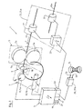
- FIG. 1 schematically shows a schematic diagram with parts of a spring coiling machine 1, which are of importance for the invention.
- the spring coiling machine 1 comprises an electronic machine control, called control 3 for short, a wire conveyor 5 with two wire feed rollers 5a, 5b, a wire former 7 having a feed part 9 comprising two support rollers 9a, 9b or a feedstock (not shown) and at least one converter 11 Controller 3 may include one or more components.
- the controller 3 may comprise a conventional machine controller and a PC or industrial computer connected thereto.
- FIG. 1 As shown embodiment of the invention are as a converter 11, a bender 11a for deflecting a spring wire, short wire 13 called in the radial direction or for forming the turns of a screw or
- Mattress spring and a deflector 11b for deflecting the wire 13 in the axial direction or for forming the pitch of the spring 15 is provided.
- the conveying direction of the wire 13 is indicated by an arrow P.
- the position and / or position of the bender 11a and the deflector 11b are via actuators, for example via actuators, stepper or servo motors with or without gear or linear motors, which may include, for example, piezoelectric translators or electric motor or pneumatically driven spindles, and controllable.
- the means 11, 11a, 11b for deforming the wire 13 to a spring 15 are adjustable depending on the configuration of the spring coiling machine 1 before and / or after and / or during the manufacture of a spring 15 by the controller 3, controllable or adjustable.
- the processing cycle or drive intervals for the updating of the position or position of the converters 11 are short and, for example, in the range of a few milliseconds to about 100 ms.
- the controller 3 comprises means for detecting input or measured variables, for example a user interface 17 with a screen display 19 and a keyboard 21 and / or a device interface 23 for connecting measuring devices 25 and / or programming or data reading devices such as, for example for inputting setpoints or default functions for the control of the converter 11 are required.
- Connected measuring device 25a for detecting wire properties comprises a measuring sensor 27 which is arranged upstream of the wire-forming machine 7 so that it can detect wire properties prior to the deformation of the wire 13 into a spring 15.
- the measuring sensor 27 can be designed to detect a wide variety of material parameters or properties of the wire 13 with any desired measuring methods. It is also possible to use a plurality of measuring sensors 27 for detecting such measured quantities.
- the first measuring device 25a comprises an eddy current measuring device, as offered, for example, by the company IBG sketcher GmbH in Germany under the brand name eddyliner® and the type designation P or Px. Devices of this type are generally used in the field of material testing and quality assurance.
- the device comprises an evaluation unit 29 and as a measuring sensor 27 a coil connected thereto.
- a further coil with a piece of reference wire 13a may be connected to the evaluation unit 29 as a reference sensor 31.
- the evaluation unit 29 controls the measuring sensor 27 sequentially with a sequence of several different frequencies in the range of about 5Hz to about 300kHz.
- the control is carried out with a sinusoidal signal.
- the drive signal may also be a superposition of different sinusoidal signals.
- the control can be carried out continuously or in the form of pulse packets.
- the evaluation unit 29 determines, for example, from the attenuation behavior of the signals and / or from other measured variables that can be influenced by these signals at several or all measurement frequencies f i, the real part R i and the imaginary part I i of the impedance Z, where the index i is an integer value between one and can take eight, for example.
- the impedance Z could also be detected, which can be influenced by the damping behavior of the excitation signals or by induction or eddy currents which are generated by the excitation signals.
- the scale on the ordinate indicates normalized values with respect to a reference value of the impedance.
- the real and imaginary parts of the impedance values determined for certain measuring frequencies f i and for the designated WA, WB, WC and WD wires accept 13 characteristic values. These values correspond to a fingerprint of the respective wire 13, which can be determined by different properties such as chemical composition, structure of the structure, internal mechanical stresses, surface treatment, electrical conductivity, permeability, temperature, external diameter, shape of the cross-sectional area, etc.
- the inner or outer diameter of a coil spring may be too small or too large and / or the pitch of the spring 15 may differ from the desired spring pitch. It is also possible that the spring 15 while in shape and shape the Default values corresponds, but has a deviating from the setpoint spring constant.
- Such deviations can be determined manually by a person, for example by visual inspection and / or by measuring. A person may then instruct the controller 3 via the user interface 17 to adjust the control of the converter 11 in such a way that the subsequently produced springs 15 again have the desired properties. The adjustment or correction may be based on empirically determined data.
- FIG. 3 shows a possible drive function for the bender 11a in the manufacture of a mattress spring.
- the horizontal direction X corresponds to the feed length of the wire 13 during spring production.
- the vertical direction Y the deflection or position or position of the bender 11 a is indicated.
- the scaling of the two coordinate directions is in each case specified normalized with respect to the maximum possible coordinate values, so that the possible value range of each coordinate extends from zero to one.
- the control curve marked K 1 corresponds to the ideal drive function for the bender 11 a for a real reference wire.
- the controller 3 may have deposited such a control cam in a memory (not shown).
- the control curve can, for example, by parameters of a polynomial function or by Fourier coefficients or Alternatively, stored as a look-up table, wherein for example, a hundred evenly distributed over the entire wire length support points, the corresponding Auslenkhong are stored.
- the controller 3 by an adapted control function K 2 (in FIG. 3 represented by a broken line) again produce springs 15 with the desired properties.
- Such an adaptation of the control function can be effected for example by multiplying the control values stored in the table by a correction factor and / or by adding or subtracting a correction value.
- the driving values can also be adjusted in such a way that non-geometric spring properties such as the spring constant or progressive springs a corresponding function with different wire properties are maintained, in which case the Shape of the springs 15, for example, the spring pitch can vary.
- the detection of deviations from spring properties can also be carried out automatically with a second measuring device 25b using suitable test sensors 33.
- a second measuring device 25b can be detected with a camera-based image processing system (no representation).
- the controller 3 can automatically adjust or correct the drive function K 1 or the drive values at the individual support points on the basis of the measured variables of the second measurement device 25b, as soon as these measured quantities are outside a tolerance range specified by the control 3.
- the adjustment of the control function K 1 can be done by means of processing instructions that are specified in the controller 3.
- the controller 3 further comprises a monitoring device (not shown) or an algorithm for determining correlations between a) the drive functions and / or corrections of these drive functions and / or spring characteristics detected by the test sensors 33 and / or deviations of these spring characteristics from the desired properties and b) the detected by the measuring sensors 27 wire properties.
- the algorithm can take into account the delay between the detection of the wire properties by the measuring sensors 27 spatially upstream of the converter 11 and the effect on the subsequently produced springs 15.
- Each of these, for example, two hundred records is provided with a reference that allows a clear assignment to the drive function K 1 for the corresponding spring type.
- This control function K 1 is also stored in the memory of the controller 3 as a look-up table with, for example, a hundred points uniformly distributed over the wire length required to produce the spring 15.
- the values stored at the support points correspond to the drive values for the bender 11a at the location of these support points.
- the controller 3 may calculate and store a first reference data set with the mean values or the median from the previously stored measured value data sets. Alternatively, the controller 3 can also directly store the measured values, which are preferably filtered and freed from stochastic interference.
- the first reference data set thus reflects a constellation of values of the first measuring device 25a, in which no correction of the drive function K 1 is required.
- the second and each further reference data set reflects a constellation of values of the first measuring device 25a, in which a correction of the drive function K 1 or another drive function K 2 , K 3 , etc. is required in order to produce springs 15 with the desired properties.
- the controller 3 After the formation of a first or further reference data set, which may include, for example, the real and imaginary parts of the impedance of the wire 13 at one or more frequencies, the controller 3 changes from the training mode to an operating mode in which no further determination of reference data records takes place.
- the controller 3 now starts a comparison algorithm which correlates the wire characteristics recorded by the measurement sensors 27 and stored as reference data sets and the corrections made at the original drive function K 1 , eg by means of multiple regression or neural networks, and searches for correlations between these quantities.
- a comparison algorithm which correlates the wire characteristics recorded by the measurement sensors 27 and stored as reference data sets and the corrections made at the original drive function K 1 , eg by means of multiple regression or neural networks, and searches for correlations between these quantities.
- linear and non-linear functions of the measured variables or of the data stored in the reference data sets are taken into account.
- Correlations occur when the control function required for the production of the springs 15 or their difference to the original control function K 1 from the original control function K 1 and the measured variables of the measuring sensors 27 or, which derive the data of the reference data records.
- the controller 3 can limit the number of measured quantities taken into account or the corresponding data in the stored data sets such that only those parameters are taken into account which have a significant contribution to the correlation function.
- the controller 3 changes the control of the converters 11 in such a way that, in addition to the stored original control function K 1 , the measured values of the measuring sensors 27 and the associated correction values or the correlation function for controlling the converter 11 are taken into account.
Description
Gegenstand der Erfindung ist eine Federwindemaschine und ein Verfahren zum Steuern einer Federwindemaschine gemäss dem Oberbegriff der Patentansprüche 1 und 5. Eine solche Maschine und ein solches Verfahren sind aus der
Aufgrund von Inhomogenitäten bzw. nicht konstanten chemischen und/oder physikalischen Eigenschaften des Drahtes können die Eigenschaften der hergestellten Federn mehr oder weniger stark von den erwünschten Solleigenschaften abweichen. So können sich beispielsweise Werkstoffeigenschaften wie Drahtdurchmesser, Verwerfungen oder Verdrehungen, Zusammensetzung des Mischgefüges, innere Spannungen oder Mikrorissfelder auf die Zugfestigkeit, den Elastizitätsmodul oder auf andere die Verformbarkeit des Drahtes beeinflussende Eigenschaften auswirken. Aufgrund von Inhomogenitäten des Drahtes können auch dessen elektrische Eigenschaften wie z.B. die Leitfähigkeit bzw. die Impedanz oder die Permeabilität innerhalb des Drahtes an unterschiedlichen Positionen unterschiedlich sein. Die Werkstoff-Inhomogenitäten können dazu führen, dass die Eigenschaften der hergestellten Federn nicht konstant sind. Insbesondere können Formparameter wie z.B. Windungsdurchmesser, Steigung usw. und/oder mechanische Eigenschaften wie z.B. die Federkonstanten beachtliche Bandbreiten aufweisen. Die Fertigung von geometrisch genauen Federn mit Eigenschaften innerhalb enger Toleranzgrenzen gestaltet sich oft schwierig.Due to inhomogeneities or non-constant chemical and / or physical properties of the wire, the properties of the produced springs may deviate more or less from the desired nominal properties. Thus, for example, material properties such as wire diameter, warping or twisting, composition of the mixed structure, internal stresses or microcracks can affect the tensile strength, the modulus of elasticity or other properties affecting the ductility of the wire. Due to inhomogeneities of the wire and its electrical properties such. the conductivity or impedance or permeability within the wire may be different at different positions. The material inhomogeneities can lead to the properties of the produced springs not being constant. In particular, shape parameters such as e.g. Coil diameter, pitch, etc., and / or mechanical properties, e.g. the spring constants have considerable bandwidths. The production of geometrically accurate springs with properties within close tolerance limits is often difficult.
Aus der
Ein Nachteil dieser Federwickelvorrichtung besteht darin, dass der Einfluss unterschiedlicher Drahteigenschaften auf physikalischen Eigenschaften der herzustellenden Feder erst beim bzw. nach dem Umformprozess erfasst werden. Erst nach der Messung von Innendurchmessern bzw. Aussendurchmessern, die von den Sollwerten abweichen, kann die Steuerung zu einer Positionskorrektur der Wickelwerkzeuge veranlasst werden. Es muss damit gerechnet werden, dass immer wieder Federn hergestellt werden, deren Federeigenschaften von den gewünschten Federeigenschaften abweichen. Falls enge Toleranzvorgaben eingehalten werden sollen, müssen solche Federn aussortiert werden.From the
A disadvantage of this spring winding device is that the influence of different wire properties on physical properties of the spring to be produced are detected only during or after the forming process. Only after the measurement of inner diameters or outside diameters, which deviate from the nominal values, the control can be made to a position correction of the winding tools. It must be expected that springs are produced time and again, whose spring characteristics differ from the desired spring properties. If tight tolerances are to be met, such springs must be sorted out.
Es ist deshalb Aufgabe der Erfindung, eine Federwindemaschine und ein Verfahren zum Herstellen von Federn, zu schaffen, bei denen erwünschte messbare Grössen möglichst wenig von vorgebbaren Sollgrössen abweichen. Gelöst wird diese Aufgabe durch eine Federwindemaschine mit einer Messvorrichtung und durch ein Verfahren zur Herstellung von Federn gemäss den Merkmalen der Patentansprüche 1 und 5.It is therefore an object of the invention to provide a spring coiling machine and a method for producing springs, in which desired measurable variables deviate as little as possible from predefinable setpoint variables. This object is achieved by a spring coiling machine with a measuring device and by a method for producing springs according to the features of patent claims 1 and 5.
Die erfindungsgemässe Federwindemaschine umfasst eine Messvorrichtung mit mindestens einem in Förderrichtung des Drahtes vor dem Umformer angeordneten Messsensor. Der oder die Messsensoren erfassen Messgrössen des umzuformenden Drahtes, die durch dessen physikalische und/oder chemische Eigenschaften gegeben oder mitbestimmt sind. Erfindungsgemäss steuert die Maschinensteuerung die Umformvorrichtung nicht nur in Abhängigkeit vorgegebener Anweisungen oder Vorschriften, sondern auch in Abhängigkeit von Messgrössen, die von den Sensoren erfasst werden, welche der Drahtumformanlage vorgelagert sind. Die Verarbeitungsvorschriften, wie die Messgrössen zu Steuergrössen für die Umformvorrichtung zu verarbeiten sind, können der Steuerung fest vorgegeben oder vorgebbar sein, sie können aber auch von der Steuerung selbst ermittelt werden. In einer bevorzugten Ausgestaltung der Erfindung kann die Steuerung weitere Eingabe- oder Messgrössen erfassen, die im Zusammenhang mit den Eigenschaften von hergestellten Federn stehen. Die Steuerung kann insbesondere manuelle Eingaben an einer Benutzerschnittstelle erfassen, also beispielsweise Korrektureingaben für die Positions- oder Lagesteuerung eines Umformers, welche dazu führen, dass die Federn die erwünschten Solleigenschaften aufweisen. Dies entspricht einem offenen Regelkreis, bei dem ein Modell mit Verarbeitungsvorschriften gebildet oder angepasst wird. Alternativ oder zusätzlich kann die Steuerung auch Messgrössen von Prüfsensoren erfassen, welche Eigenschaften der hergestellten Federn oder Abweichungen dieser Eigenschaften von erwünschten, in einem Speichermedium der Steuerung speicherbaren Solleigenschaften repräsentieren.
Die Steuerung ist erfindungsgemäss so ausgebildet, dass sie Messgrössen der vorgelagerten Messsensoren und Eingabe- oder Messgrössen, die im Zusammenhang mit den Eigenschaften von hergestellten Federn stehen, zueinander in Beziehung setzen und Korrelationen zwischen den Messgrössen und/oder aus den Messgrössen hergeleiteten Funktionen herstellen kann. Die Steuerung kann auf diese Weise Gesetzmässigkeiten zwischen den Messgrössen der vorgelagerten Messsensoren und den Eigenschaften der hergestellten Federn ermitteln. Insbesondere kann die Steuerung unter Berücksichtigung der Messgrössen der Messsensoren die Umformvorrichtung in der Weise ansteuern bzw. beeinflussen, dass die hergestellten Federn die gewünschten bzw. vorgegebenen Solleigenschaften aufweisen und somit Schwankungen der Drahteigenschaften ausgleichen. Anhand einiger Figuren wird eine bevorzugte Ausgestaltung der erfindungsgemässen Federwindemaschine und des erfindungsgemässen Verfahrens zur Herstellung von Federn genauer beschrieben. Dabei zeigen
- Figur 1
- eine schematische Prinzipskizze von Teilen einer Federwindemaschine,
- Figur 2
- eine Darstellung von Messwerten eines Wirbelstrommessgeräts,
- Figur 3
- eine Ansteuerfunktion für einen Umformer
According to the invention, the controller is designed such that it can correlate measured variables of the upstream measuring sensors and input variables or measuring quantities which are associated with the properties of manufactured springs and can produce correlations between the measured variables and / or functions derived from the measured variables. In this way, the controller can determine regularities between the measured variables of the upstream measuring sensors and the properties of the springs produced. In particular, the control, taking into account the measured variables of the measuring sensors, can control or influence the shaping device in such a way that the springs produced have the desired or predetermined nominal properties and thus compensate for fluctuations in the wire properties. On the basis of some figures, a preferred embodiment of the inventive spring coiling machine and the inventive method for the production of springs is described in more detail. Show
- FIG. 1
- a schematic schematic diagram of parts of a spring coiling machine,
- FIG. 2
- a representation of measured values of an eddy-current measuring instrument,
- FIG. 3
- a drive function for a converter
Matratzenfeder und ein Abweiser 11b zum Ablenken des Drahtes 13 in axialer Richtung bzw. zum Formen der Steigung der Feder 15 vorgesehen. Die Förderrichtung des Drahtes 13 ist durch einen Pfeil P angegeben. Die Position und/oder Lage des Biegers 11a und des Abweisers 11b sind über Aktoren, beispielsweise über Stell-, Schritt- oder Servomotoren mit oder ohne Getriebe oder über Linearmotoren, die z.B. piezoelektische Translatoren oder elektromotorisch oder pneumatisch antreibbare Spindeln umfassen können, einstell- und steuerbar. Die Mittel 11, 11a, 11b zum Verformen des Drahtes 13 zu einer Feder 15 sind je nach Ausgestaltung der Federwindemaschine 1 vor und/oder nach und/oder während der Herstellung einer Feder 15 durch die Steuerung 3 verstellbar, steuerbar oder regelbar. Vorzugsweise sind der Verarbeitungszyklus bzw. die Ansteuerintervalle für die Aktualisierung der Position oder Lage der Umformer 11 kurz und liegen beispielsweise im Bereich von wenigen Millisekunden bis etwa 100ms. Die Steuerung 3 umfasst Mittel zum Erfassen von Eingabe - oder Messgrössen, also beispielsweise eine Benutzerschnittstelle 17 mit einer Bildschirm-Anzeige 19 und einer Tastatur 21 und/oder eine Geräteschnittstelle 23 zum Anschliessen von Messvorrichtungen 25 und/oder Programmier- oder Datenlesevorrichtungen, wie sie beispielsweise zum Eingeben von Sollwerten oder Vorgabefunktionen für die Ansteuerung des Umformers 11 benötigt werden. Eine erste, mit der Steuerung 3 verbundene Messvorrichtung 25a zum Erfassen von Drahteigenschaften umfasst einen Messsensor 27 der stromaufwärts vor der Drahtumformanlage 7 so angeordnet ist, dass er Drahteigenschaften vor der Umformung des Drahtes 13 zu einer Feder 15 erfassen kann. Grundsätzlich kann der Messsensor 27 zur Erfassung unterschiedlichster Werkstoffparameter bzw. Eigenschaften des Drahtes 13 mit beliebigen Messverfahren ausgebildet sein. Es können auch mehrere Messsensoren 27 zur Erfassung solcher Messgrössen eingesetzt sein. So kann beispielsweise ein optischer CCD-Sensor Abmessungen und/oder Oberflächenstruktur des Drahtes 13 und ein Temperatursensor dessen Temperatur und eine Spule Wirbelströme oder Impedanzen erfassen. Vorzugsweise umfasst die erste Messvorrichtung 25a ein Wirbelstrom-Messgerät, wie es beispielsweise von der Firma IBG Prüfcomputer GmbH in Deutschland unter der Markenbezeichnung eddyliner® und der Typenbezeichnung P bzw. Px angeboten wird. Geräte dieses Typs werden in der Regel im Bereich Materialprüfung und Qualitätssicherung eingesetzt. In der erfindungsgemässen Anwendung umfasst das Gerät eine Auswerteeinheit 29 und als Messsensor 27 eine daran angeschlossene Spule. Zusätzlich kann bei bestimmten Arten von Wirbelstrom-Messgeräten als Referenzsensor 31 eine weitere Spule mit einem Stück Referenzdraht 13a an die Auswerteeinheit 29 angeschlossen sein. Mit dieser Anordnung kann ein allfälliger Offset der Messvorrichtung 25a verringert oder vermieden werden, wodurch der Messbereich und die Auflösung für den auszumessenden Draht 13 optimiert werden. Die Auswerteeinheit 29 steuert den Messsensor 27 nacheinander mit einer Sequenz von mehreren unterschiedlichen Frequenzen im Bereich von etwa 5Hz bis zu etwa 300kHz an. Vorzugsweise erfolgt die Ansteuerung mit einem sinusförmigen Signal. Alternativ kann das Ansteuersignal auch eine Überlagerung verschiedener sinusförmiger Signale sein. Die Ansteuerung kann kontinuierlich oder in Form von Pulspaketen erfolgen. Die Auswerteeinheit 29 ermittelt z.B. aus dem Dämpfungsverhalten der Signale und/oder aus anderen Messgrössen, die durch diese Signale beeinflussbar sind bei mehreren oder allen Messfrequenzen fi den Realteil Ri und den Imaginärteil Ii der Impedanz Z wobei der Index i ganzzahlige Werte zwischen eins und beispielsweise acht annehmen kann. Anstelle oder zusätzlich zur Impedanz Z könnten auch andere Messgrössen erfasst werden, die durch das Dämpfungsverhalten der Anregungssignale oder durch Induktions- bzw. Wirbelströme, welche durch die Anregungssignale generiert werden, beeinflussbar sind.Mattress spring and a deflector 11b for deflecting the
Diese Messwerte werden an die Steuerung 3 übermittelt oder können von der Steuerung 3 abgefragt werden.These measured values are transmitted to the controller 3 or can be queried by the controller 3.
Deutlich ist zu erkennen, dass die Real- und Imaginäranteile der ermittelten Impedanzwerte für gewisse Messfrequenzen fi und für die mit WA, WB, WC und WD bezeichneten Drähte 13 charakteristische Werte annehmen. Diese Werte entsprechen einem Fingerabdruck des jeweiligen Drahtes 13, der durch unterschiedliche Eigenschaften wie z.B. chemische Zusammensetzung, Struktur des Gefüges, innere mechanische Spannungen, Oberflächenbehandlung, elektrische Leitfähigkeit, Permeabilität, Temperatur, Aussendurchmesser, Form der Querschnittfläche etc. bestimmt sein kann.It is clearly visible that the real and imaginary parts of the impedance values determined for certain measuring frequencies f i and for the designated WA, WB, WC and WD wires accept 13 characteristic values. These values correspond to a fingerprint of the
Bei der Umformung des Drahtes 13 zu einer Feder 15 können solche Drahteigenschaften bei unveränderter Einstellung der Umformer 11 dazu führen, dass die tatsächlichen Eigenschaften von den erwünschten Solleigenschaften der Feder 15 abweichen. So können beispielsweise der Innen - oder Aussendurchmesser einer Schraubenfeder zu klein oder zu gross sein und/oder die Steigung der Feder 15 kann von der erwünschten Federsteigung abweichen. Ebenso ist es möglich, dass die Feder 15 zwar in Form und Gestalt den Vorgabewerten entspricht, aber eine vom Sollwert abweichende Federkonstante aufweist.When forming the
Solche Abweichungen können manuell durch eine Person, beispielsweise durch visuelle Kontrolle und/oder durch Ausmessen ermittelt werden. Eine Person kann die Steuerung 3 anschliessend über die Benutzerschnittstelle 17 anweisen, die Ansteuerung der Umformer 11 in der Weise anzupassen, dass die nachfolgend hergestellten Federn 15 wieder die erwünschten Eigenschaften aufweisen. Die Einstellung oder Korrektur kann auf empirisch ermittelten Daten beruhen.Such deviations can be determined manually by a person, for example by visual inspection and / or by measuring. A person may then instruct the controller 3 via the
Wenn die Eigenschaften der mit der Ansteuerfunktion K1 hergestellten Federn 15 von den gewünschten Eigenschaften abweichen, also beispielsweise der Aussendurchmesser der Federn 15 Aufgrund veränderter Drahteigenschaften zu gross oder zu klein ist, oder die Federsteigung ausserhalb eines Toleranzbereichs von beispielsweise 2% oder 5% eines vorgegebenen Sollwertes liegt, kann die Steuerung 3 durch eine angepasste Ansteuerfunktion K2 (in
Alternativ oder zusätzlich kann die Erfassung von Abweichungen von Federeigenschaften auch automatisch mit einer zweiten Messvorrichtung 25b mit geeigneten Prüfsensoren 33 erfolgen. So können beispielsweise der Aussendurchmesser eines Endrings und/oder der Innendurchmesser der engsten Windung und/oder die Federsteigung mit einem kamerabasierten Bildverarbeitungssystem (keine Darstellung) erfasst werden. In Analogie zur manuellen Anpassung der Ansteuerfunktion K1 kann die Steuerung 3 die Ansteuerfunktion K1 bzw. die Ansteuerwerte an den einzelnen Stützstellen automatisch anhand der Messgrössen der zweiten Messvorrichtung 25b anpassen bzw. korrigieren, sobald diese Messgrössen ausserhalb eines der Steuerung 3 vorgegebenen Toleranzbereichs liegen. Die Anpassung der Ansteuerfunktion K1 kann mittels Verarbeitungsvorschriften erfolgen, die in der Steuerung 3 vorgegeben sind.Alternatively or additionally, the detection of deviations from spring properties can also be carried out automatically with a second measuring device 25b using
Die Steuerung 3 umfasst im weiteren eine Überwachungseinrichtung (nicht dargestellt) bzw. einen Algorithmus zum Feststellen von Korrelationen zwischen a) den Ansteuerfunktionen und/oder Korrekturen dieser Ansteuerfunktionen und/oder von den Prüfsensoren 33 erfassten Federeigenschaften und/oder von Abweichungen dieser Federeigenschaften von den Solleigenschaften und b) den von den Messsensoren 27 erfassten Drahteigenschaften.The controller 3 further comprises a monitoring device (not shown) or an algorithm for determining correlations between a) the drive functions and / or corrections of these drive functions and / or spring characteristics detected by the
Der Algorithmus kann die Verzögerung zwischen der Erfassung der Drahteigenschaften durch die dem Umformer 11 räumlich vorgelagerten Messsensoren 27 und der Auswirkung auf die anschliessend hergestellten Federn 15 berücksichtigen.The algorithm can take into account the delay between the detection of the wire properties by the measuring
Eine Möglichkeit für die Ermittlung solcher Korrelationen wird nachfolgend beispielhaft erläutert:
- Nach der erstmaligen Inbetriebnahme der Federwindemaschine 1 startet die Steuerung 3 automatisch oder alternativ auf entsprechende Anweisung einer Bedienperson einen Trainingsmodus. Für jede herzustellende Feder 15 speichert die Steuerung 3 die von der ersten Messvorrichtung 25a ermittelten Werte als Datensätze, vorausgesetzt, dass die Eigenschaften der hergestellten Federn 15 innerhalb der vorgegebenen Toleranzgrenzen liegen.
- After the first start-up of the spring coiling machine 1, the controller 3 starts a training mode automatically or alternatively on the appropriate instruction of an operator. For each
spring 15 to be manufactured, the controller 3 stores the values determined by the first measuring device 25a as data sets, provided that the properties of the produced springs 15 are within the predetermined tolerance limits.
Jeder dieser beispielsweise zweihundert Datensätze ist mit einem Verweis versehen, der eine eindeutige Zuordnung zur Ansteuerfunktion K1 für den entsprechenden Federtyp zulässt. Diese Ansteuerfunktion K1 ist als Lookup-Tabelle mit z.B. hundert gleichmässig über die zur Herstellung der Feder 15 erforderliche Drahtlänge verteilten Stützstellen ebenfalls im Speicher der Steuerung 3 hinterlegt. Die an den Stützstellen gespeicherten Werte entsprechen den Ansteuerwerten für den Bieger 11a am Ort dieser Stützstellen.Each of these, for example, two hundred records is provided with a reference that allows a clear assignment to the drive function K 1 for the corresponding spring type. This control function K 1 is also stored in the memory of the controller 3 as a look-up table with, for example, a hundred points uniformly distributed over the wire length required to produce the
Die Steuerung 3 kann einen ersten Referenzdatensatz mit den Mittelwerten oder dem Median aus den zuvor gespeicherten Messwert-Datensätzen berechnen und speichern. Alternativ kann die Steuerung 3 auch direkt die Messwerte, welche vorzugsweise gefiltert und von stochastischen Störungen befreit sind, speichern. Der erste Referenzdatensatz widerspiegelt demnach eine Konstellation von Werten der ersten Messvorrichtung 25a, bei der keine Korrektur der Ansteuerfunktion K1 erforderlich ist.The controller 3 may calculate and store a first reference data set with the mean values or the median from the previously stored measured value data sets. Alternatively, the controller 3 can also directly store the measured values, which are preferably filtered and freed from stochastic interference. The first reference data set thus reflects a constellation of values of the first measuring device 25a, in which no correction of the drive function K 1 is required.
In analoger Weise kann die Steuerung 3 automatisch oder auf manuelle Anforderung weitere Referenzdatensätze bilden, z.B. wenn eines der folgenden Kriterien erfüllt ist:
- Die ursprüngliche Ansteuerfunktion K1 wurde zu einer neuen bzw. korrigierten Ansteuerfunktion K2 abgeändert, damit die herzustellenden Federn 15 die erwünschten Solleigenschaften haben
- Eine oder mehrere Messgrössen der ersten Messvorrichtung 25a weichen signifikant von den in den vorgängig gespeicherten Referenzdatensätzen enthaltenen Werten ab
- Die Steuerung 3 stellt aufgrund von Änderungen der Messgrössen der zweiten Messvorrichtung 25b fest, dass die Federeigenschaften signifikant von den Sollwerten abweichen, welche ebenfalls in einem Speichermedium der Steuerung 3 hinterlegt sind
- The original drive function K 1 has been changed to a new or corrected drive function K 2 , so that the
springs 15 to be produced have the desired nominal properties - One or more measured quantities of the first measuring device 25a differ significantly from the values contained in the previously stored reference data sets
- The controller 3 determines that the spring characteristics are significantly different from those due to changes in the measured quantities of the second measuring device 25b Deviate setpoints, which are also stored in a storage medium of the controller 3
Der zweite und jeder weitere Referenzdatensatz widerspiegelt eine Konstellation von Werten der ersten Messvorrichtung 25a, bei der eine Korrektur der Ansteuerfunktion K1 bzw. eine andere Ansteuerfunktion K2, K3 usw. erforderlich ist, um Federn 15 mit den gewünschten Eigenschaften produzieren zu können.The second and each further reference data set reflects a constellation of values of the first measuring device 25a, in which a correction of the drive function K 1 or another drive function K 2 , K 3 , etc. is required in order to produce
Nach der Bildung eines ersten oder weiteren Referenzdatensatzes, der z.B. die Real- und Imaginärteile der Impedanz des Drahtes 13 bei einer oder mehreren Frequenzen umfassen kann, wechselt die Steuerung 3 vom Trainingsmodus in einen Betriebsmodus, in dem keine weitere Ermittlung von Referenzdatensätzen erfolgt. Die Steuerung 3 startet nun einen Vergleichsalgorithmus, der die von den Messsensoren 27 erfassten und als Referenzdatensätze gespeicherten Drahteigenschaften und die an der ursprünglichen Ansteuerfunktion K1 vorgenommenen Korrekturen z.B. mittels multipler Regression oder neuronaler Netze zueinander in Beziehung setzt und Korrelationen zwischen diesen Grössen sucht. Dabei werden zusätzlich zu den Messgrössen der Messsensoren 27 bzw. zu den Daten der Referenzdatensätze auch lineare und nichtlineare Funktionen der Messgrössen bzw. der in den Referenzdatensätzen gespeicherten Daten berücksichtigt. Korrelationen liegen dann vor, wenn sich die zur Herstellung der Federn 15 erforderliche Ansteuerfunktion oder deren Differenz zur ursprünglichen Ansteuerfunktion K1 aus der ursprünglichen Ansteuerfunktion K1 und den Messgrössen der Messsensoren 27 bzw, der Daten der Referenzdatensätze herleiten lässt. Bei der Ermittlung von Korrelationsfunktionen kann die Steuerung 3 die Anzahl berücksichtigter Messgrössen bzw. der entsprechenden Daten in den gespeicherten Datensätzen derart beschränken, dass nur jene Parameter berücksichtigt werden, die einen signifikanten Beitrag an der Korrelationsfunktion haben.After the formation of a first or further reference data set, which may include, for example, the real and imaginary parts of the impedance of the
Wenn solche Korrelationen vorliegen, ändert die Steuerung 3 die Ansteuerung der Umformer 11 in der Weise, dass zusätzlich zur gespeicherten ursprünglichen Ansteuerfunktion K1 auch die Messwerte der Messsensoren 27 und die zugeordneten Korrekturwerte bzw. die Korrelationsfunktion zur Ansteuerung des Umformers 11 berücksichtigt werden.If such correlations are present, the controller 3 changes the control of the
Claims (8)
- Spring winding machine (1) for the production of springs (15), comprising a wire transport device (5) and a wire transformation system (7) that can be controlled by a machine control (3) with at least one electronically controllable transformer (11), wherein at least one measuring sensor (27) of a measuring device (25a) is arranged in front of the transformer (11) in relation to the direction of transport of the wire (13) which is to be transformed, and wherein the wire transformation system (7) can be influenced by a measuring variable registered by the measuring sensor (27), characterised in that the measuring sensor (27) comprises a measuring coil for non-contact measurement of the measuring variables.
- Spring winding machine (1) according to claim 4, characterised in that the measuring device (25a) comprises a reference sensor (31).
- Spring winding machine (1) according to any one of the claims 1 or 2, characterised in that the measuring device (25a) comprises means for registering impedances and/or measuring variables which can be influenced by induction currents or eddy currents.
- Spring winding machine (1) according to any one of the claims 1 to 3, characterised in that the machine control (3) comprises input devices (21) and/or registration devices (33) for inputting and/or registering spring properties or deviations of the spring properties from predetermined or predeterminable target variables and/or for inputting target variables.
- A method that can be performed with a spring winding machine (1) according to any one of claims 1 to 4, characterised in that one transformer or a number of transformers (11, 11 a, 11b) is or are controlled depending on one or a number of predetermined or predeterminable control function(s) (K1) and depending on the at least one measuring variable, registered by the measuring coil, of the measuring device (25a).
- Method according to claim 5, characterised in that the control (3) saves and further processes values determined by the measuring device (25a).
- Method according to claim 6, characterised in that the control (3) processes, automatically or on manual request, measuring variables of values determined by the measuring device (25a), to obtain reference data sets which also influence the control of the transformers (11, 11a, 11b) during the production of springs (15).
- Method according to claim 7, characterised in that the control (3) determines correlations between the reference data sets and the control function of the transformers (11, 11a, 11b).
Applications Claiming Priority (2)
| Application Number | Priority Date | Filing Date | Title |
|---|---|---|---|
| CH8272003 | 2003-05-13 | ||
| PCT/CH2004/000284 WO2004101193A1 (en) | 2003-05-13 | 2004-05-10 | Spring winding machine and method for controlling a spring winding machine |
Publications (2)
| Publication Number | Publication Date |
|---|---|
| EP1622732A1 EP1622732A1 (en) | 2006-02-08 |
| EP1622732B1 true EP1622732B1 (en) | 2012-11-07 |
Family
ID=33438094
Family Applications (1)
| Application Number | Title | Priority Date | Filing Date |
|---|---|---|---|
| EP04731869A Not-in-force EP1622732B1 (en) | 2003-05-13 | 2004-05-10 | Spring winding machine and method for controlling a spring winding machine |
Country Status (4)
| Country | Link |
|---|---|
| US (1) | US7458243B2 (en) |
| EP (1) | EP1622732B1 (en) |
| CN (1) | CN100372625C (en) |
| WO (1) | WO2004101193A1 (en) |
Cited By (1)
| Publication number | Priority date | Publication date | Assignee | Title |
|---|---|---|---|---|
| DE102020209068A1 (en) | 2020-07-20 | 2022-01-20 | Wafios Aktiengesellschaft | Process and spring coiling machine for the production of helical springs |
Families Citing this family (13)
| Publication number | Priority date | Publication date | Assignee | Title |
|---|---|---|---|---|
| US8269831B2 (en) * | 2005-11-29 | 2012-09-18 | Posco | Wire guider of air guide type |
| CN100404160C (en) * | 2006-07-21 | 2008-07-23 | 黄金堂 | Full function spring press |
| AT505743B1 (en) * | 2007-03-30 | 2009-07-15 | Trumpf Maschinen Austria Gmbh | METHOD FOR DETERMINING AN ADJUSTMENT PARAMETER VALUE OF A BENDING PRESSURE |
| ITRM20080078A1 (en) * | 2008-02-12 | 2009-08-13 | Cml Intarnational S P A | METHOD OF VERIFICATION AND COMMAND TO CURVE IN AN CONTINUOUS WAY A PIECE EXTENDED ACCORDING TO VARIABLE CURCATORS SPOKES AND MACHINE SO COMMANDED |
| DE102010014385B4 (en) * | 2010-04-06 | 2011-12-08 | Wafios Ag | Method and device for producing coil springs by spring winches, and spring coiling machine |
| JP5756609B2 (en) * | 2010-07-30 | 2015-07-29 | 日本発條株式会社 | Coil spring manufacturing equipment |
| CN103143645B (en) * | 2013-03-20 | 2014-12-10 | 沈阳飞机工业(集团)有限公司 | Manufacturing tooling of cloud-shaped torsion spring |
| JP5777184B2 (en) * | 2014-02-14 | 2015-09-09 | 旭精機工業株式会社 | Forming machine |
| KR101419698B1 (en) * | 2014-03-25 | 2014-07-21 | 대원강업 주식회사 | hot formed coiling machine |
| JP6420690B2 (en) * | 2015-02-26 | 2018-11-07 | 日本発條株式会社 | Coiling machine and coil spring manufacturing method |
| US20190039118A1 (en) * | 2016-02-03 | 2019-02-07 | Spühl Gmbh | Coil Spring Winding Apparatus and Method of Winding A Coil Spring |
| FR3050266B1 (en) * | 2016-04-15 | 2021-02-12 | Somfy Sas | PROCESS FOR CHECKING THE CONFORMITY OF A SPRING, PROCESS FOR MANUFACTURING SUCH A SPRING AND SPRING THUS CHECKING |
| TWI654039B (en) | 2018-04-27 | 2019-03-21 | 展望系統股份有限公司 | Spring producing system |
Family Cites Families (13)
| Publication number | Priority date | Publication date | Assignee | Title |
|---|---|---|---|---|
| GB2137344A (en) * | 1983-03-16 | 1984-10-03 | Standard Telephones Cables Ltd | Flaw protection in wire drawing |
| DE3804913A1 (en) * | 1987-02-20 | 1988-09-01 | Itaya Seisakusho | DEVICE AND METHOD FOR PRODUCING SPRINGS |
| CN2039238U (en) * | 1988-06-02 | 1989-06-14 | 陕西省宝鸡市标准件弹簧厂 | Forming machine for spring washer |
| JPH05115936A (en) * | 1991-10-25 | 1993-05-14 | Chuo Spring Co Ltd | Coiling method for wire rod for manufacturing coil spring |
| JP3172221B2 (en) * | 1991-11-18 | 2001-06-04 | 株式会社東京コイリングマシン製作所 | Manufacturing method of coil spring |
| US5477715A (en) * | 1992-04-08 | 1995-12-26 | Reell Precision Manufacturing Corporation | Adaptive spring winding device and method |
| US5470319A (en) * | 1994-06-20 | 1995-11-28 | Critical Device Corporation | Needleless injection site |
| DE4443503A1 (en) * | 1994-12-07 | 1996-06-13 | Uwe Dr Ing Otzen | Mfr. of helical springs by automatic spring winding machine |
| EP0796158B1 (en) * | 1994-12-07 | 1998-05-27 | WAFIOS Maschinenfabrik GmbH & Co. Kommanditgesellschaft | Method and device for the optimized production of helical springs on automatic spring-winding machines |
| DE19604408C1 (en) * | 1996-02-07 | 1997-05-28 | Allevard Federn Gmbh | Spring screw manufacturing method |
| JP2812433B2 (en) * | 1996-08-23 | 1998-10-22 | 株式会社板屋製作所 | Spring manufacturing equipment |
| US5875664A (en) * | 1997-12-23 | 1999-03-02 | L&P Property Management Company | Programmable servo-motor quality controlled continuous multiple coil spring forming method and apparatus |
| CN2360188Y (en) * | 1998-09-27 | 2000-01-26 | 金苗兴 | Spring coiling machine |
-
2004
- 2004-05-10 CN CNB2004800127098A patent/CN100372625C/en not_active Expired - Fee Related
- 2004-05-10 WO PCT/CH2004/000284 patent/WO2004101193A1/en active Application Filing
- 2004-05-10 EP EP04731869A patent/EP1622732B1/en not_active Not-in-force
- 2004-05-10 US US10/556,372 patent/US7458243B2/en not_active Expired - Fee Related
Cited By (1)
| Publication number | Priority date | Publication date | Assignee | Title |
|---|---|---|---|---|
| DE102020209068A1 (en) | 2020-07-20 | 2022-01-20 | Wafios Aktiengesellschaft | Process and spring coiling machine for the production of helical springs |
Also Published As
| Publication number | Publication date |
|---|---|
| EP1622732A1 (en) | 2006-02-08 |
| CN100372625C (en) | 2008-03-05 |
| CN1787889A (en) | 2006-06-14 |
| WO2004101193A1 (en) | 2004-11-25 |
| US7458243B2 (en) | 2008-12-02 |
| US20060230803A1 (en) | 2006-10-19 |
Similar Documents
| Publication | Publication Date | Title |
|---|---|---|
| EP1622732B1 (en) | Spring winding machine and method for controlling a spring winding machine | |
| EP0603244B1 (en) | Process for controlling a production machine, in particular an injection moulding machine | |
| DE102010010895B3 (en) | Method for producing coil springs by spring winches, and spring coiling machine | |
| EP2243584B1 (en) | Method and device for manufacturing container frames from such sheet metal | |
| DE102010014386B4 (en) | Method for producing coil springs by spring winches, and spring coiling machine | |
| DE3324444A1 (en) | FAULT DETECTION DEVICE WITH ROTATING MEASURING HEAD | |
| WO1996017701A1 (en) | Method and device for the optimized production of helical springs on automatic spring-winding machines | |
| WO2012092909A1 (en) | Method for incrementally forming sheet metal structures, in particular for forming pipes or the like | |
| DE102011004167A1 (en) | Method and device for automated straightening of elongated material | |
| DE19518804A1 (en) | Process control | |
| DE3804913C2 (en) | ||
| EP0946312A1 (en) | Method for automatic conducting of a straightening process | |
| EP2148751B1 (en) | Method and device for bending sheet metal sections | |
| EP0656071B1 (en) | Process and device for regulating the calorific output in a continuous annealing and processing line for continuously cast metal products | |
| DE19534189A1 (en) | Spring winding device with reproducible parameters and narrow tolerances | |
| DE102005012384A1 (en) | Free bending of workpiece such as sheet useful in sheet bending operations involves construction of bending and correction curves and application of the corrections to further bending | |
| EP1383212B1 (en) | Apparatus and method for quality assurance of crimp connections | |
| WO2019145338A1 (en) | Stretching-bending-straightening system and method for the actuation thereof | |
| EP0936514B1 (en) | Method and device for controlling the drive system of a machine and/or an installation | |
| EP3987631A1 (en) | Method and device for cutting winding elements to length and bending them | |
| DE2428022A1 (en) | METHOD AND DEVICE FOR TESTING THE NUMBER OF WINDINGS OF A COIL | |
| DE10331127A1 (en) | Method for influencing a bending process | |
| EP3554753B1 (en) | Method of and device for roll welding of container bodies | |
| EP4013556B1 (en) | Method for the online determination of at least one rolling parameter, and rolling mill with a device for the online determination of at least one rolling parameter | |
| DE102018126336B4 (en) | Method for controlling a bending machine, control for controlling a bending machine and bending machine |
Legal Events
| Date | Code | Title | Description |
|---|---|---|---|
| PUAI | Public reference made under article 153(3) epc to a published international application that has entered the european phase |
Free format text: ORIGINAL CODE: 0009012 |
|
| 17P | Request for examination filed |
Effective date: 20050704 |
|
| AK | Designated contracting states |
Kind code of ref document: A1 Designated state(s): AT BE BG CH CY CZ DE DK EE ES FI FR GB GR HU IE IT LI LU MC NL PL PT RO SE SI SK TR |
|
| DAX | Request for extension of the european patent (deleted) | ||
| RIN1 | Information on inventor provided before grant (corrected) |
Inventor name: REISSNER, JOSEF Inventor name: RUZOVIC, MARTIN |
|
| 17Q | First examination report despatched |
Effective date: 20110407 |
|
| GRAP | Despatch of communication of intention to grant a patent |
Free format text: ORIGINAL CODE: EPIDOSNIGR1 |
|
| GRAS | Grant fee paid |
Free format text: ORIGINAL CODE: EPIDOSNIGR3 |
|
| GRAA | (expected) grant |
Free format text: ORIGINAL CODE: 0009210 |
|
| AK | Designated contracting states |
Kind code of ref document: B1 Designated state(s): AT BE BG CH CY CZ DE DK EE ES FI FR GB GR HU IE IT LI LU MC NL PL PT RO SE SI SK TR |
|
| REG | Reference to a national code |
Ref country code: GB Ref legal event code: FG4D Free format text: NOT ENGLISH |
|
| REG | Reference to a national code |
Ref country code: CH Ref legal event code: NV Representative=s name: GACHNANG AG PATENTANWAELTE, CH Ref country code: CH Ref legal event code: EP Ref country code: AT Ref legal event code: REF Ref document number: 582774 Country of ref document: AT Kind code of ref document: T Effective date: 20121115 |
|
| REG | Reference to a national code |
Ref country code: IE Ref legal event code: FG4D Free format text: LANGUAGE OF EP DOCUMENT: GERMAN |
|
| REG | Reference to a national code |
Ref country code: DE Ref legal event code: R096 Ref document number: 502004013859 Country of ref document: DE Effective date: 20130103 |
|
| REG | Reference to a national code |
Ref country code: NL Ref legal event code: VDEP Effective date: 20121107 |
|
| PG25 | Lapsed in a contracting state [announced via postgrant information from national office to epo] |
Ref country code: NL Free format text: LAPSE BECAUSE OF FAILURE TO SUBMIT A TRANSLATION OF THE DESCRIPTION OR TO PAY THE FEE WITHIN THE PRESCRIBED TIME-LIMIT Effective date: 20121107 Ref country code: FI Free format text: LAPSE BECAUSE OF FAILURE TO SUBMIT A TRANSLATION OF THE DESCRIPTION OR TO PAY THE FEE WITHIN THE PRESCRIBED TIME-LIMIT Effective date: 20121107 Ref country code: ES Free format text: LAPSE BECAUSE OF FAILURE TO SUBMIT A TRANSLATION OF THE DESCRIPTION OR TO PAY THE FEE WITHIN THE PRESCRIBED TIME-LIMIT Effective date: 20130218 Ref country code: SE Free format text: LAPSE BECAUSE OF FAILURE TO SUBMIT A TRANSLATION OF THE DESCRIPTION OR TO PAY THE FEE WITHIN THE PRESCRIBED TIME-LIMIT Effective date: 20121107 |
|
| PG25 | Lapsed in a contracting state [announced via postgrant information from national office to epo] |
Ref country code: PL Free format text: LAPSE BECAUSE OF FAILURE TO SUBMIT A TRANSLATION OF THE DESCRIPTION OR TO PAY THE FEE WITHIN THE PRESCRIBED TIME-LIMIT Effective date: 20121107 Ref country code: GR Free format text: LAPSE BECAUSE OF FAILURE TO SUBMIT A TRANSLATION OF THE DESCRIPTION OR TO PAY THE FEE WITHIN THE PRESCRIBED TIME-LIMIT Effective date: 20130208 Ref country code: PT Free format text: LAPSE BECAUSE OF FAILURE TO SUBMIT A TRANSLATION OF THE DESCRIPTION OR TO PAY THE FEE WITHIN THE PRESCRIBED TIME-LIMIT Effective date: 20130307 Ref country code: SI Free format text: LAPSE BECAUSE OF FAILURE TO SUBMIT A TRANSLATION OF THE DESCRIPTION OR TO PAY THE FEE WITHIN THE PRESCRIBED TIME-LIMIT Effective date: 20121107 Ref country code: CY Free format text: LAPSE BECAUSE OF FAILURE TO SUBMIT A TRANSLATION OF THE DESCRIPTION OR TO PAY THE FEE WITHIN THE PRESCRIBED TIME-LIMIT Effective date: 20121107 |
|
| PG25 | Lapsed in a contracting state [announced via postgrant information from national office to epo] |
Ref country code: SK Free format text: LAPSE BECAUSE OF FAILURE TO SUBMIT A TRANSLATION OF THE DESCRIPTION OR TO PAY THE FEE WITHIN THE PRESCRIBED TIME-LIMIT Effective date: 20121107 Ref country code: CZ Free format text: LAPSE BECAUSE OF FAILURE TO SUBMIT A TRANSLATION OF THE DESCRIPTION OR TO PAY THE FEE WITHIN THE PRESCRIBED TIME-LIMIT Effective date: 20121107 Ref country code: BG Free format text: LAPSE BECAUSE OF FAILURE TO SUBMIT A TRANSLATION OF THE DESCRIPTION OR TO PAY THE FEE WITHIN THE PRESCRIBED TIME-LIMIT Effective date: 20130207 Ref country code: EE Free format text: LAPSE BECAUSE OF FAILURE TO SUBMIT A TRANSLATION OF THE DESCRIPTION OR TO PAY THE FEE WITHIN THE PRESCRIBED TIME-LIMIT Effective date: 20121107 Ref country code: DK Free format text: LAPSE BECAUSE OF FAILURE TO SUBMIT A TRANSLATION OF THE DESCRIPTION OR TO PAY THE FEE WITHIN THE PRESCRIBED TIME-LIMIT Effective date: 20121107 |
|
| PG25 | Lapsed in a contracting state [announced via postgrant information from national office to epo] |
Ref country code: RO Free format text: LAPSE BECAUSE OF FAILURE TO SUBMIT A TRANSLATION OF THE DESCRIPTION OR TO PAY THE FEE WITHIN THE PRESCRIBED TIME-LIMIT Effective date: 20121107 Ref country code: IT Free format text: LAPSE BECAUSE OF FAILURE TO SUBMIT A TRANSLATION OF THE DESCRIPTION OR TO PAY THE FEE WITHIN THE PRESCRIBED TIME-LIMIT Effective date: 20121107 |
|
| PLBE | No opposition filed within time limit |
Free format text: ORIGINAL CODE: 0009261 |
|
| STAA | Information on the status of an ep patent application or granted ep patent |
Free format text: STATUS: NO OPPOSITION FILED WITHIN TIME LIMIT |
|
| 26N | No opposition filed |
Effective date: 20130808 |
|
| BERE | Be: lapsed |
Owner name: SPUHL A.G. ST. GALLEN Effective date: 20130531 |
|
| REG | Reference to a national code |
Ref country code: DE Ref legal event code: R097 Ref document number: 502004013859 Country of ref document: DE Effective date: 20130808 |
|
| PG25 | Lapsed in a contracting state [announced via postgrant information from national office to epo] |
Ref country code: MC Free format text: LAPSE BECAUSE OF FAILURE TO SUBMIT A TRANSLATION OF THE DESCRIPTION OR TO PAY THE FEE WITHIN THE PRESCRIBED TIME-LIMIT Effective date: 20121107 |
|
| GBPC | Gb: european patent ceased through non-payment of renewal fee |
Effective date: 20130510 |
|
| REG | Reference to a national code |
Ref country code: IE Ref legal event code: MM4A |
|
| PG25 | Lapsed in a contracting state [announced via postgrant information from national office to epo] |
Ref country code: BE Free format text: LAPSE BECAUSE OF NON-PAYMENT OF DUE FEES Effective date: 20130531 |
|
| REG | Reference to a national code |
Ref country code: FR Ref legal event code: ST Effective date: 20140131 |
|
| PG25 | Lapsed in a contracting state [announced via postgrant information from national office to epo] |
Ref country code: IE Free format text: LAPSE BECAUSE OF NON-PAYMENT OF DUE FEES Effective date: 20130510 Ref country code: GB Free format text: LAPSE BECAUSE OF NON-PAYMENT OF DUE FEES Effective date: 20130510 |
|
| PG25 | Lapsed in a contracting state [announced via postgrant information from national office to epo] |
Ref country code: FR Free format text: LAPSE BECAUSE OF NON-PAYMENT OF DUE FEES Effective date: 20130531 |
|
| REG | Reference to a national code |
Ref country code: DE Ref legal event code: R082 Ref document number: 502004013859 Country of ref document: DE |
|
| PG25 | Lapsed in a contracting state [announced via postgrant information from national office to epo] |
Ref country code: LU Free format text: LAPSE BECAUSE OF NON-PAYMENT OF DUE FEES Effective date: 20130510 Ref country code: HU Free format text: LAPSE BECAUSE OF FAILURE TO SUBMIT A TRANSLATION OF THE DESCRIPTION OR TO PAY THE FEE WITHIN THE PRESCRIBED TIME-LIMIT; INVALID AB INITIO Effective date: 20040510 |
|
| PGFP | Annual fee paid to national office [announced via postgrant information from national office to epo] |
Ref country code: CH Payment date: 20160511 Year of fee payment: 13 Ref country code: DE Payment date: 20160504 Year of fee payment: 13 |
|
| PGFP | Annual fee paid to national office [announced via postgrant information from national office to epo] |
Ref country code: TR Payment date: 20160401 Year of fee payment: 13 Ref country code: AT Payment date: 20160425 Year of fee payment: 13 |
|
| REG | Reference to a national code |
Ref country code: DE Ref legal event code: R119 Ref document number: 502004013859 Country of ref document: DE |
|
| REG | Reference to a national code |
Ref country code: CH Ref legal event code: PL |
|
| REG | Reference to a national code |
Ref country code: AT Ref legal event code: MM01 Ref document number: 582774 Country of ref document: AT Kind code of ref document: T Effective date: 20170510 |
|
| PG25 | Lapsed in a contracting state [announced via postgrant information from national office to epo] |
Ref country code: AT Free format text: LAPSE BECAUSE OF NON-PAYMENT OF DUE FEES Effective date: 20170510 |
|
| PG25 | Lapsed in a contracting state [announced via postgrant information from national office to epo] |
Ref country code: LI Free format text: LAPSE BECAUSE OF NON-PAYMENT OF DUE FEES Effective date: 20170531 Ref country code: CH Free format text: LAPSE BECAUSE OF NON-PAYMENT OF DUE FEES Effective date: 20170531 |
|
| PG25 | Lapsed in a contracting state [announced via postgrant information from national office to epo] |
Ref country code: DE Free format text: LAPSE BECAUSE OF NON-PAYMENT OF DUE FEES Effective date: 20171201 |
|
| PG25 | Lapsed in a contracting state [announced via postgrant information from national office to epo] |
Ref country code: TR Free format text: LAPSE BECAUSE OF NON-PAYMENT OF DUE FEES Effective date: 20170510 |