EP1622529B1 - Vis à os avec moyen de guidage d'un tournevis - Google Patents
Vis à os avec moyen de guidage d'un tournevis Download PDFInfo
- Publication number
- EP1622529B1 EP1622529B1 EP04751682A EP04751682A EP1622529B1 EP 1622529 B1 EP1622529 B1 EP 1622529B1 EP 04751682 A EP04751682 A EP 04751682A EP 04751682 A EP04751682 A EP 04751682A EP 1622529 B1 EP1622529 B1 EP 1622529B1
- Authority
- EP
- European Patent Office
- Prior art keywords
- bone
- bone engaging
- engaging portion
- combination
- end portion
- Prior art date
- Legal status (The legal status is an assumption and is not a legal conclusion. Google has not performed a legal analysis and makes no representation as to the accuracy of the status listed.)
- Expired - Lifetime
Links
- 210000000988 bone and bone Anatomy 0.000 title claims abstract description 235
- 238000004891 communication Methods 0.000 claims abstract description 10
- 239000000463 material Substances 0.000 claims description 61
- 239000007943 implant Substances 0.000 claims description 18
- 238000006073 displacement reaction Methods 0.000 claims description 15
- 230000008468 bone growth Effects 0.000 claims description 10
- 230000001737 promoting effect Effects 0.000 claims description 10
- 239000002639 bone cement Substances 0.000 claims description 7
- 239000000126 substance Substances 0.000 claims description 4
- 230000000921 morphogenic effect Effects 0.000 claims description 2
- 102000004169 proteins and genes Human genes 0.000 claims description 2
- 108090000623 proteins and genes Proteins 0.000 claims description 2
- 230000007246 mechanism Effects 0.000 description 20
- 238000003780 insertion Methods 0.000 description 13
- 230000037431 insertion Effects 0.000 description 13
- 210000002517 zygapophyseal joint Anatomy 0.000 description 10
- 210000001519 tissue Anatomy 0.000 description 6
- -1 instruments Substances 0.000 description 5
- 238000004873 anchoring Methods 0.000 description 4
- 239000000560 biocompatible material Substances 0.000 description 4
- 238000000034 method Methods 0.000 description 4
- 229910001285 shape-memory alloy Inorganic materials 0.000 description 4
- 239000002775 capsule Substances 0.000 description 3
- 230000014759 maintenance of location Effects 0.000 description 3
- RTAQQCXQSZGOHL-UHFFFAOYSA-N Titanium Chemical compound [Ti] RTAQQCXQSZGOHL-UHFFFAOYSA-N 0.000 description 2
- XAGFODPZIPBFFR-UHFFFAOYSA-N aluminium Chemical compound [Al] XAGFODPZIPBFFR-UHFFFAOYSA-N 0.000 description 2
- 229910052782 aluminium Inorganic materials 0.000 description 2
- 230000008901 benefit Effects 0.000 description 2
- 239000013078 crystal Substances 0.000 description 2
- 230000004927 fusion Effects 0.000 description 2
- 238000010079 rubber tapping Methods 0.000 description 2
- 239000010935 stainless steel Substances 0.000 description 2
- 229910001220 stainless steel Inorganic materials 0.000 description 2
- 229910052719 titanium Inorganic materials 0.000 description 2
- 239000010936 titanium Substances 0.000 description 2
- 239000004809 Teflon Substances 0.000 description 1
- 229920006362 Teflon® Polymers 0.000 description 1
- 210000003484 anatomy Anatomy 0.000 description 1
- 238000005452 bending Methods 0.000 description 1
- 230000015572 biosynthetic process Effects 0.000 description 1
- 239000004568 cement Substances 0.000 description 1
- 230000008859 change Effects 0.000 description 1
- 230000001419 dependent effect Effects 0.000 description 1
- 239000006185 dispersion Substances 0.000 description 1
- 239000012530 fluid Substances 0.000 description 1
- 230000006870 function Effects 0.000 description 1
- 208000014674 injury Diseases 0.000 description 1
- 230000007794 irritation Effects 0.000 description 1
- 229910000734 martensite Inorganic materials 0.000 description 1
- 239000004033 plastic Substances 0.000 description 1
- 229920000642 polymer Polymers 0.000 description 1
- 239000011253 protective coating Substances 0.000 description 1
- 239000012781 shape memory material Substances 0.000 description 1
- 239000007779 soft material Substances 0.000 description 1
- 239000007787 solid Substances 0.000 description 1
- 230000009466 transformation Effects 0.000 description 1
- 230000008733 trauma Effects 0.000 description 1
Images


Classifications
-
- A—HUMAN NECESSITIES
- A61—MEDICAL OR VETERINARY SCIENCE; HYGIENE
- A61B—DIAGNOSIS; SURGERY; IDENTIFICATION
- A61B17/00—Surgical instruments, devices or methods, e.g. tourniquets
- A61B17/56—Surgical instruments or methods for treatment of bones or joints; Devices specially adapted therefor
- A61B17/58—Surgical instruments or methods for treatment of bones or joints; Devices specially adapted therefor for osteosynthesis, e.g. bone plates, screws, setting implements or the like
- A61B17/88—Osteosynthesis instruments; Methods or means for implanting or extracting internal or external fixation devices
- A61B17/8875—Screwdrivers, spanners or wrenches
- A61B17/8886—Screwdrivers, spanners or wrenches holding the screw head
- A61B17/8888—Screwdrivers, spanners or wrenches holding the screw head at its central region
-
- A—HUMAN NECESSITIES
- A61—MEDICAL OR VETERINARY SCIENCE; HYGIENE
- A61B—DIAGNOSIS; SURGERY; IDENTIFICATION
- A61B17/00—Surgical instruments, devices or methods, e.g. tourniquets
- A61B17/56—Surgical instruments or methods for treatment of bones or joints; Devices specially adapted therefor
- A61B17/58—Surgical instruments or methods for treatment of bones or joints; Devices specially adapted therefor for osteosynthesis, e.g. bone plates, screws, setting implements or the like
- A61B17/68—Internal fixation devices, including fasteners and spinal fixators, even if a part thereof projects from the skin
- A61B17/84—Fasteners therefor or fasteners being internal fixation devices
- A61B17/86—Pins or screws or threaded wires; nuts therefor
- A61B17/8605—Heads, i.e. proximal ends projecting from bone
- A61B17/861—Heads, i.e. proximal ends projecting from bone specially shaped for gripping driver
- A61B17/8615—Heads, i.e. proximal ends projecting from bone specially shaped for gripping driver at the central region of the screw head
-
- A—HUMAN NECESSITIES
- A61—MEDICAL OR VETERINARY SCIENCE; HYGIENE
- A61B—DIAGNOSIS; SURGERY; IDENTIFICATION
- A61B17/00—Surgical instruments, devices or methods, e.g. tourniquets
- A61B17/56—Surgical instruments or methods for treatment of bones or joints; Devices specially adapted therefor
- A61B17/58—Surgical instruments or methods for treatment of bones or joints; Devices specially adapted therefor for osteosynthesis, e.g. bone plates, screws, setting implements or the like
- A61B17/68—Internal fixation devices, including fasteners and spinal fixators, even if a part thereof projects from the skin
- A61B17/84—Fasteners therefor or fasteners being internal fixation devices
- A61B17/86—Pins or screws or threaded wires; nuts therefor
- A61B17/864—Pins or screws or threaded wires; nuts therefor hollow, e.g. with socket or cannulated
-
- A—HUMAN NECESSITIES
- A61—MEDICAL OR VETERINARY SCIENCE; HYGIENE
- A61B—DIAGNOSIS; SURGERY; IDENTIFICATION
- A61B17/00—Surgical instruments, devices or methods, e.g. tourniquets
- A61B17/56—Surgical instruments or methods for treatment of bones or joints; Devices specially adapted therefor
- A61B17/58—Surgical instruments or methods for treatment of bones or joints; Devices specially adapted therefor for osteosynthesis, e.g. bone plates, screws, setting implements or the like
- A61B17/88—Osteosynthesis instruments; Methods or means for implanting or extracting internal or external fixation devices
- A61B17/8802—Equipment for handling bone cement or other fluid fillers
- A61B17/8805—Equipment for handling bone cement or other fluid fillers for introducing fluid filler into bone or extracting it
- A61B17/8811—Equipment for handling bone cement or other fluid fillers for introducing fluid filler into bone or extracting it characterised by the introducer tip, i.e. the part inserted into or onto the bone
-
- A—HUMAN NECESSITIES
- A61—MEDICAL OR VETERINARY SCIENCE; HYGIENE
- A61B—DIAGNOSIS; SURGERY; IDENTIFICATION
- A61B17/00—Surgical instruments, devices or methods, e.g. tourniquets
- A61B17/56—Surgical instruments or methods for treatment of bones or joints; Devices specially adapted therefor
- A61B17/58—Surgical instruments or methods for treatment of bones or joints; Devices specially adapted therefor for osteosynthesis, e.g. bone plates, screws, setting implements or the like
- A61B17/88—Osteosynthesis instruments; Methods or means for implanting or extracting internal or external fixation devices
- A61B17/8802—Equipment for handling bone cement or other fluid fillers
- A61B17/8805—Equipment for handling bone cement or other fluid fillers for introducing fluid filler into bone or extracting it
- A61B17/8816—Equipment for handling bone cement or other fluid fillers for introducing fluid filler into bone or extracting it characterised by the conduit, e.g. tube, along which fluid flows into the body or by conduit connections
-
- A—HUMAN NECESSITIES
- A61—MEDICAL OR VETERINARY SCIENCE; HYGIENE
- A61B—DIAGNOSIS; SURGERY; IDENTIFICATION
- A61B17/00—Surgical instruments, devices or methods, e.g. tourniquets
- A61B17/56—Surgical instruments or methods for treatment of bones or joints; Devices specially adapted therefor
- A61B17/58—Surgical instruments or methods for treatment of bones or joints; Devices specially adapted therefor for osteosynthesis, e.g. bone plates, screws, setting implements or the like
- A61B17/68—Internal fixation devices, including fasteners and spinal fixators, even if a part thereof projects from the skin
- A61B17/70—Spinal positioners or stabilisers ; Bone stabilisers comprising fluid filler in an implant
- A61B17/7097—Stabilisers comprising fluid filler in an implant, e.g. balloon; devices for inserting or filling such implants
- A61B17/7098—Stabilisers comprising fluid filler in an implant, e.g. balloon; devices for inserting or filling such implants wherein the implant is permeable or has openings, e.g. fenestrated screw
Definitions
- the present invention generally relates to an improved bone anchor.
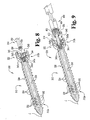
- the bone anchor 10 is generally comprised of a bone engaging portion 12 and an elongate guiding portion 14.
- the bone engaging portion 12 is adapted for anchoring to bone.
- the bone engaging portion 12 is adapted for anchoring to vertebral bone.
- the elongate guiding portion 14 extends from the bone engaging portion 12 and is adapted to guide or deliver various devices, materials, instruments, implants and/or other elements to the bone engaging portion 12.
- the elongate guiding portion 14 is configured to releasably engage the bone engaging portion 12 so as to allow selective removal therefrom, the details of which will be discussed below.
- the bone engaging portion 12 comprises a bone screw extending generally along a longitudinal axis L between a distal end portion 12a and a proximal end portion 12b.
- the bone screw 12 generally includes a threaded shank portion 20 and a proximal head portion 22.
- the threaded shank portion 20 defines external threads 24 configured to engage internal threads formed along a passage in the bone.
- the threads 24 are cancellous threads configured to engage vertebral bone.
- the distal end of the threaded shank 20 may define one or more cutting flutes 26 extending across at least one of the threads 24 to provide the bone anchor 10 with self-tapping and/or self-cutting capabilities.
- the proximal head 22 preferably has a generally smooth outer surface that is devoid of sharp corners or edges to avoid trauma or irritation of adjacent tissue. In one embodiment, the proximal head 22 has a spherical-shaped configuration. However, other configurations are also contemplated, such as, for example, a conical or cylindrical configuration.
- the outer surface of the proximal head 22 may include a number of flattened areas ( FIG. 1 ) for engagement with a driving tool.
- the bone engaging portion 12 of the bone anchor 10 defines a cannula passage 30 extending generally along the longitudinal axis L.
- the cannula passage 30 is illustrated as extending partially through the bone engaging portion 12 so as to define a partially-cannulated bone screw, it should be understood that in other embodiments of the invention, the cannula passage 30 may extend entirely through the bone engaging portion 12 so as to define a fully-cannulated bone screw.
- the bone engaging portion 12 of the bone anchor 10 defines a number of fenestration openings 32 extending through the side wall of the bone engaging portion in a transverse direction and in communication with the axial cannula passage 30.
- the transverse fenestration openings 32 are confined to the distal end portion 12a of the bone engaging portion 12, and in a more specific embodiment are disposed along the distal-most one-third of the bone engaging portion 12.
- the fenestration openings 32 may be disposed along other portions of the bone engaging portion 12, including along the proximal portion 12b or along the entire length of the bone engaging portion 12.
- the cannula passage 30 and the transverse fenestration openings 32 cooperate to deliver a material to select regions of the bone in which the bone engaging portion 12 is engaged.
- Such materials may include, for example, bone cement, a bone growth promoting material such as a bone morphogenic protein (BMP), or other bio-compatible materials.
- BMP bone morphogenic protein
- the entire amount of the material is delivered into the cannula passage 30 and out the transverse fenestration openings 32 in a lateral direction, with no material being discharged from the distal end of the bone engaging portion 12 in an axial direction.
- delivery of the material to select portions of the bone can be accomplished in a controlled and efficient manner, the details of which will be discussed below.
- the proximal head 22 of the bone engaging portion 12 includes a shaped passage or recess 40 communicating with the cannula passage 30.
- the shaped recess 40 is configured to receive a shaped end portion of the elongate guiding portion 14 therein to couple the elongate guiding portion 14 with the bone engaging portion 12, the details of which will be discussed below.
- the proximal head 22 may comprise a shaped end portion that is receivable within a shaped passage or recess defined in the elongate guiding portion 14 to couple the elongate guiding portion 14 with the bone engaging portion 12.
- the shaped recess 40 defined in the proximal head 22 includes a connecting portion 42, a receiving portion 44, and a retaining portion 46 disposed between the connecting portion 42 and the receiving portion 44.
- the connecting portion 42 comprises a spherical-shaped socket sized to engagingly receive a correspondingly shaped end portion of the guiding portion 14 therein to connect the guiding portion 14 to the bone engaging portion 12.
- the receiving portion 44 comprises an axially-extending receptacle or opening sized to engagingly receive a corresponding end portion of an instrument, implant, mechanism, and/or other types of elements therein.
- the receiving portion 44 may take on a number of different shapes and configurations, including a hexagonal shape, a circular or elliptical shape, a square or rectangular shape, a Torx TM -type configuration, or any other shape or configuration that would occur to one of skill in the art.
- the retention portion 46 comprises an annular shoulder extending between the socket 42 and the receptacle 44.
- the retention portion 46 defines an inner diameter sized somewhat smaller than the spherical-shaped socket 42 to retain a corresponding end portion of the guiding portion 14 therein. It should be understood, however, that other shapes, sizes and/or configurations of the connecting portion 42, receiving portion 44, and retaining portion 46 are also contemplated as falling within the scope of the present invention.
- the elongate guiding portion 14 comprises a shaped end portion 50 and an elongate shaft portion 52 extending therefrom.
- the shaped end portion 50 has a ball or spherical-shaped configuration corresponding to the size and shape of the spherical-shaped socket 42 defined by the shaped recess 40 in the proximal head 22 of the bone engaging portion 12.
- the spherical shaped ball 50 has an outer diameter sized in close tolerance with the inner diameter of the spherical-shaped socket 42 so as to provide a relatively close fit therebetween while still allowing the ball 50 to freely rotate within the socket 42.
- shaped recess 42 and the shaped end portion 50 are illustrated and described as having spherical configurations, it should be understood that other shapes and configurations are also contemplated as falling within the scope of the present invention, examples of which will be illustrated and described below.
- the shaped end portion 50 is engagingly received within the shaped recess 42 in a manner allowing selective removal of the elongate guiding portion 14 from the bone engaging portion 12.
- the annular shoulder 46 positioned adjacent the spherical-shaped socket 42 has an inner diameter sized somewhat smaller than the outer diameter of the spherical-shaped ball portion 50.
- the annular shoulder 46 serves to selectively retain the ball portion 50 within the socket 42, which in turn selectively engages the elongate guiding portion 14 with the bone engaging portion 12. Since the annular shoulder 46 is sized somewhat smaller than the ball portion 50, in one embodiment of the invention, the ball portion 50 is press fit into the socket 42. As a result, the annular shoulder 46 and/or the ball portion 50 are slightly deformed during insertion and removal of the ball portion 50 into/from the socket 42.
- the ball portion 50 is engaged within the socket 42 so as to allow angular displacement of the elongate guiding portion 14 relative to the bone engaging portion 12 up to a displacement angle ⁇ (as measured relative to the longitudinal axis L).
- the ball portion 50 and the socket 42 cooperate to provide the bone anchor 10 with multi-axial capabilities, allowing angular displacement of the elongate guiding portion 14 in multiple directions relative to the bone engaging portion 12 up to the displacement angle ⁇ .
- the displacement angle ⁇ falls within a range of about 5 degrees to about 30 degrees.
- other displacement angles ⁇ are also contemplated as falling within the scope of the present invention.
- the ball portion 50 and the socket 42 may cooperate to limit or prohibit angular displacement of the elongate guiding portion 14 relative to the bone engaging portion 12 in one or more directions.
- the elongate shaft portion 52 extends from the ball portion 50 and is adapted to guide or direct various devices, instruments, implants and/or other elements toward the proximal head 22 of the bone engaging portion 12, the details of which will be discussed below.
- the elongate shaft portion 52 is flexible so as to allow the elongate shaft portion 52 to be reshaped or bent either before or during displacement of the devices, instruments, implants and/or other elements toward the proximal head 22 of the bone engaging portion 12.
- the elongate shaft portion 52 may alternatively have a substantially rigid configuration so as to prevent or resist deflection of the elongate shaft portion 52 during displacement of the devices, instruments, implants and/or other elements toward the proximal head 22 of the bone engaging portion 12.
- the elongate shaft portion 52 is at least partially formed of a flexible, malleable or pliable material to allow for reshaping or bending.
- a flexible, malleable or pliable material may include, for example, an aluminum material, a shape-memory material, a plastic material, or certain types of stainless steel or titanium. If a relatively soft material is used, such as an aluminum material, the elongate shaft portion 52 may be covered with a protective coating such as an anodized oxide film or one or more layers of an elastomeric polymer such as Teflon.
- the elongate shaft portion 52 is formed of a substantially rigid or non-malleable material, such as, for example, stainless steel or titanium. The use of a rigid material allows the elongate shaft portion 52 to maintain a predetermined shape or configuration.
- the elongate shaft portion 52 is at least partially formed of a shape-memory alloy (SMA)
- SMA shape-memory alloy
- the elongate shaft portion 52 may be bent or reshaped from an initial configuration to a different configuration and automatically reformed back toward the initial configuration without having to manually bend the elongate shaft portion 52 back toward its initial configuration.
- This shape-memory characteristic occurs when the SMA is transformed from a martensitic crystal phase to an austenitic crystal phase. This phase transformation can occur with or without a corresponding change in temperature. Further details regarding the features and characteristics of SMA materials are more fully described in U.S. Patent No. 5,551,871 to Besselink and in U.S. Patent No. 5,597,378 to Jervis .
- an axial passageway 54 extends along the elongate shaft portion 52 and through the shaped end portion 50, thereby defining a fully-cannulated elongate guiding portion 14.
- the shaped end portion 50 and the elongate shaft portion 52 need not necessarily define an axial passageway 54, but may instead define a solid, non-cannulated elongate guiding portion 14.
- the axial passageway 54 is disposed in fluid communication with the cannula passage 30.
- various materials may be delivered through the axial passageway 54 from a location remote from the bone engaging portion 12 and into the cannula passage 30 for distribution to the transverse fenestration openings 32.
- such materials may include bone cement or a bone growth promoting material such as BMP.
- the bone engaging portion 12 of the bone anchor 10 is anchored to the vertebra V with the elongate guiding portion 14 extending from the proximal head 22.
- the distal end portion of the threaded shank 20 may define one or more cutting flutes 26 to provide the bone engaging portion 12 with self-tapping and/or self-cutting capabilities to facilitate insertion of the bone engaging portion 12 into the vertebra V.
- the elongate shaft 52 has a length such that at least the proximal end portion of the elongate shaft 52 extends outside of the patient's body when the bone engaging portion 12 is anchored to bone, such as, for example, to the vertebra V.
- various types of devices, instruments, implants and/or other elements may be advanced along the elongate shaft 52 from a location outside of the patient's body to a location adjacent the proximal head 22 of the bone engaging portion 12.
- Such devices, instruments, implants and/or other elements may be slidingly advanced along the length of the elongate shaft 52 toward the bone engaging portion 12.
- other methods of advancement along the length of the elongate shaft 52 are also possible.
- the elongate guiding portion 14 may be selectively removed from the bone engaging portion 12 to provide a low profile anchoring structure.
- the elongate shaft 52 of the guiding portion 14 is sized and configured to slidably engage a surgical instrument 90 to guide the distal end portion of the instrument 90 into engagement with the proximal head 22 of the bone engaging portion 12.
- the surgical instrument 90 is configured as a driver instrument generally comprised of a shaft 92 and a handle 94.
- the shaft 92 defines an axial passage 95 extending at least partially therethrough and sized to receive the elongate shaft 52 of the guiding portion 14 therein.
- the distal end portion 96 of the shaft 92 is preferably sized and configured for engagement within the receiving portion 44 defmed by the proximal head 22 of the bone anchor 10 to facilitate driving of the bone engaging portion 12 into and/or out of bone.
- the receiving portion 44, and likewise the distal end portion 96 of the instrument shaft 92 may take on a number of different shapes and configurations, including a hexagonal shape, a circular or elliptical shape, a square or rectangular shape, a Torx TM -type configuration, or any other shape or configuration that would occur to one of skill in the art.
- the distal-most end of the shaft 92 may define a tapered surface 98 to aid in insertion of the distal end portion 96 into the receiving portion 44 of the proximal head 22.
- the distal end portion of the instrument 90 may be configured with a receptacle or socket-type fitting for engagement over the proximal head 22 of the bone engaging portion 12 to facilitate driving of the bone engaging portion 12 into and/or out of bone.
- the driver instrument 90 may be engaged with the proximal end portion of the elongate shaft 52 at a location outside of the patient's body via insertion of the proximal end portion of the shaft 52 into the axial passage 95 defined within the driver shaft 92.
- the elongate shaft 52 may then be used to guide the driver instrument 90 through a visually-obstructed opening, such as, for example a relatively small access portal (not shown) in the patient's skin or other bodily tissue and/or through a relatively narrow tissue protection device, such as, for example, a cannula tube, to facilitate engagement of the distal end portion 96 of the instrument 90 with the proximal head 22 of the bone anchor 10.
- the elongate guiding portion 14 is engaged with the bone engaging portion 12 in such a manner as to allow angular displacement of the elongate guiding portion 14 relative to the bone engaging portion 12 ( FIG. 3 ).
- guidance of the driver instrument 90 toward the proximal head 22 of the bone anchor 10 in directions transverse to the longitudinal axis L is possible.
- displacement of the driver instrument 90 does not necessarily have to occur along the longitudinal axis L.
- the instrument 90 may be guided toward the proximal head 22 of the bone engaging portion 12 in angular directions relative to the longitudinal axis L, up to and including the displacement angle ⁇ illustrated in FIG. 3 .
- the guiding portion 14 of the bone anchor 10 is used to guide an injector or delivery mechanism 70 into engagement with the proximal head 22 of the bone engaging portion 12.
- the injector mechanism 70 is in turn configured to deliver a material into the cannula passage 30 of the bone engaging portion 12, out the transverse fenestration openings 32, and into the surrounding bone tissue, the details of which will be discussed below.
- the injector mechanism 70 is configured as a syringe.
- other types and configurations of mechanisms, devices and systems for injecting or delivering a material into the cannula passage 30 and out the transverse openings 32 are also contemplated as would occur to one of skill in the art.
- the injector mechanism 70 generally includes a receptacle portion 72 and a plunger portion 74.
- the receptacle portion 72 defines a hollow interior 75 for receiving an amount of material 88 therein.
- the receptacle portion 74 also includes a distal tip portion 76 that is sized and configured for engagement within the receiving portion 44 defined within the proximal head 22 of the bone anchor 10 to facilitate delivery of the material 88 into the cannula passage 30.
- the receiving portion 44 and likewise the distal tip portion 76 of the injector mechanism 70, may take on a number of different shapes and configurations, including a hexagonal shape, a circular or elliptical shape, a square or rectangular shape, or any other shape or configuration that would occur to one of skill in the art.
- the distal-most end of the tip portion 76 may define a tapered surface 78 to aid in the insertion of the tip portion 76 into the receiving portion 44 of the proximal head 22.
- the distal end portion of the injector mechanism 70 may be configured with a receptacle or socket-type fitting for engagement over the proximal head 22 of the bone engaging portion 12 to facilitate delivery of the material 88 into the cannula passage 30.
- the plunger portion 74 of the injector mechanism 70 includes a main body portion that is sized and shaped for displacement along the hollow interior 75 of the receptacle portion 72 to inject the material 88 into the cannula passage 30 of the bone anchor 10.
- the plunger portion 74 includes an end portion 80 that functions in a piston-like manner to force the material 88 through the hollow interior 75 of the receptacle 72, out the tip portion 76, and into the cannula passage 30.
- the end portion 80 of the plunger 74 defines an axial passage 82 extending therethrough that is sized and shaped to receive the elongate shaft 52 of the guiding portion 14 therein.
- the distally-facing surface of the end portion 80 may be inwardly tapered toward the axial passage 82 to aid in the insertion of the elongate shaft 52 into the axial passage 82.
- the injector mechanism 70 may be engaged with the proximal end portion of the elongate shaft 52 at a location outside of the patient's body via insertion of the proximal end portion of the shaft 52 through the tip portion 76 and into the hollow interior 75 of the receptacle 72. If required, the proximal end portion of the shaft 52 may also be inserted into the axial passage 82 defined by the end portion 80 of the plunger 74. The elongate shaft 52 may then be used to guide the injector mechanism 70 through a visually-obstructed opening and/or through a relatively narrow tissue protection device to facilitate engagement of the distal end portion 76 of the injector mechanism 70 with the proximal head 22 of the bone anchor 10.
- the elongate guiding portion 14 is engaged with the bone engaging portion 12 in such a manner as to allow angular displacement of the elongate guiding portion 14 relative to the bone engaging portion 12.
- guidance of the injector mechanism 70 toward the proximal head 22 of the bone anchor 10 in directions transverse to the longitudinal axis L is possible.
- the spherical-shaped end portion 50 of the elongate guiding portion 14 may include one or more passages 58 extending therethrough to provide communication between the receiving portion 44 of the passage 40 and the cannula passage 30 to facilitate delivery of the material 88 into the cannula passage 30.
- the material 88 is in turn conveyed through the cannula passage 30 and is dispensed out of the transverse fenestration openings 32 to a location laterally adjacent the bone engaging portion 12 of the bone anchor 10.
- the material 88 may be delivered to the cannula passage 30 via an axial passageway 54 extending through the elongate guiding portion 14 ( FIGS. 2 and 3 ) of the bone anchor 10. In this manner, the material 88 may be conveyed through the axial passageway 54 and delivered to the cannula passage 30 via a delivery system or injector mechanism located remote from the proximal head 22 of the bone engaging portion 12, and possibly from a location entirely outside of the patient's body.
- various materials may delivered via the bone engaging portion 12 of the bone anchor 10, such as, for example, bone cement, a bone growth promoting material, or other bio-compatible materials.
- the material 88 delivered into the bone engaging portion 12 via the injector mechanism 70 is bone cement.
- the cement material 88 cures or hardens, thereby forming a mantle M of material about the threaded shank 20.
- the mantle M of material serves to enhance engagement of the bone engaging portion 12 to the vertebra V, thereby preventing or at least substantially resisting bone anchor pull-out.
- the bone growth promoting material may similarly be delivered into the cannula passage 30 and out the fenestration openings 32 to promote bone growth in areas laterally adjacent the threaded shank 20 of the bone anchor 10.
- each of the fenestration openings 32 are disposed along the distal end portion of the threaded shank 20, and more particularly along the distal-most one-third of the threaded shank 20, thereby limiting formation of the mantle M of material about the distal end portion of the threaded shank 20. Additionally, since the cannula passage 30 does not extend entirely through the bone engaging portion 12, the entire amount of the material 88 is dispersed out the transverse fenestration openings 32 in a lateral direction, with no material 88 being discharged from the distal end of the bone engaging portion 12 in an axial direction.
- the bone anchor 100 is configured similar to the bone anchor 10 illustrated and described above, generally comprising a bone engaging portion 112 and an elongate guiding portion 114 adapted to guide or deliver various devices, materials, instruments, implants and/or other elements to the bone engaging portion 112.
- the bone engaging portion 112 comprises a bone screw having a distal end portion 112a and a proximal end portion 112b, and includes a threaded shank portion 120 and a proximal head portion 122.
- the threaded shank portion 120 defines external threads 124 configured to engage internal threads formed along a passage in bone.
- the bone engaging portion 112 defines a cannula passage 130 extending axially from the proximal end portion 112b toward the distal end portion 112a, and a number of transverse fenestration openings 132 in communication with the cannula passage 130 and positioned along the distal end portion 112a.
- the proximal head 122 of the bone engaging portion 112 includes a shaped passage or recess 140 communicating with the cannula passage 130.
- the shaped recess 140 is configured to receive a correspondingly shaped end portion of the elongate guiding portion 114 therein to selectively couple the elongate guiding portion 114 with the bone engaging portion 112, the details of which will be discussed below.
- the shaped recess 140 defined in the proximal head 122 includes a connecting portion 142 and a receiving portion 144.
- the connecting portion 142 comprises a cylindrical-shaped passage sized to engagingly receive an end portion of the guiding portion 114 therein.
- the cylindrical-shaped passage 142 defines internal threads 143 adapted to threadingly engage an end portion of the guiding portion 114.
- the receiving portion 144 comprises an axially-extending receptacle or opening sized to engagingly receive a corresponding end portion of an instrument, implant, mechanism, and/or other types of elements therein, examples of which have been illustrated and described above with regard to the bone anchor 10.
- the elongate guiding portion 114 comprises a shaped end portion 150 and an elongate shaft portion 152 extending therefrom.
- the shaped end portion 150 has a cylindrical-shaped configuration defining external threads 151 adapted for engagement within the internally threaded passage 142 defined in the proximal head 122 of the bone engaging portion 112.
- the threading engagement between the externally threaded end portion 150 and the internally threaded passage 142 releasably engages the elongate guiding portion 114 to the bone engaging portion 112 and also allows for selective removal of the elongate guiding portion 114 therefrom.
- the distally-facing surface of the threaded end portion 150 may be tapered to facilitate insertion into and threading engagement with the internally threaded passage 142.
- the elongate shaft portion 152 extends from the threaded end portion 150 and is adapted to guide or direct various devices, instruments, implants and/or other elements toward the proximal head 122 of the bone engaging portion 112.
- an axial passageway 154 extends along the elongate shaft portion 152 and through the threaded end portion 150 to allow delivery of a material to the cannula passage 130 from a location remote from the bone engaging portion 112 for distribution out of the transverse fenestration openings 132.
- the bone anchor 200 is configured similar to the bone anchor 100 illustrated and described above, generally comprising a bone engaging portion 212 and an elongate guiding portion 214 adapted to guide or deliver various devices, materials, instruments, implants and/or other elements to the bone engaging portion 212.
- the bone engaging portion 212 comprises a bone screw having a distal end portion 212a and a proximal end portion 212b, and includes a threaded shank portion 220 and a proximal head portion 222.
- the threaded shank portion 220 defines external threads 224 configured to engage internal threads formed along a passage in bone.
- the bone engaging portion 212 defines a cannula passage 230 extending axially from the proximal end portion 212b toward the distal end portion 212a, and a number of transverse fenestration openings 232 in communication with the cannula passage 230 and positioned along the distal end portion 212a.
- the proximal head 222 of the bone engaging portion 212 includes a shaped passage or recess 240 communicating with the cannula passage 230.
- the shaped recess 240 is configured to receive a correspondingly shaped end portion of the elongate guiding portion 214 therein to selectively couple the elongate guiding portion 214 with the bone engaging portion 212.
- the shaped recess 240 defined in the proximal head 222 includes a connecting portion 242 and a receiving portion 244.
- the connecting portion 242 comprises a cylindrical-shaped passage sized to engagingly receive a correspondingly shaped end portion of the guiding portion 214 therein.
- the receiving portion 244 comprises an axially-extending receptacle or opening sized to engagingly receive a corresponding end portion of an instrument, implant, mechanism, and/or other types of elements therein, examples of which have been illustrated and described above with regard to the bone anchor 10.
- the elongate guiding portion 214 comprises a shaped end portion 250 and an elongate shaft portion 252 extending therefrom.
- the shaped end portion 250 has a cylindrical-shaped configuration sized and shaped for releasable engagement within the cylindrical-shaped passage 242 defined in the proximal head 222 of the bone engaging portion 212 and allowing for selective removal of the elongate guiding portion 214 therefrom.
- the elongate shaft portion 252 extends from the shaped end portion 250 and is adapted to guide or direct various devices, instruments, implants and/or other elements toward the proximal head 222 of the bone engaging portion 212.
- an axial passageway 254 extends along the elongate shaft portion 252 and through the shaped end portion 250 to allow delivery of a material to the cannula passage 230 from a location remote from the bone engaging portion 212 for distribution out of the transverse fenestration openings 232.
- a seal 256 may be engaged between the shaped end portion 250 of the elongate guiding portion 214 and the proximal head 222 of the bone engaging portion 212 to provide a fluid-tight seal therebetween.
- the seal 256 comprises an O-ring disposed between a distally-facing surface of the shaped end portion 250 and an annular shoulder 258 located at the bottom of the cylindrical-shaped passage 242 of the recess 240.
- the distally-facing surface of the shaped end portion 250 and/or the annular shoulder 258 may define an annular retention groove (not shown) sized and shaped to receive the O-ring 256 therein to maintain the O-ring 256 in the proper position.
- a seal may be positioned about the periphery of the shaped end portion 250 to provide a fluid-tight seal between the guiding portion 214 and the bone engaging portion 212.
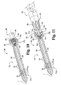
- the bone anchor 300 is configured similar to the bone anchor 100 illustrated and described above, generally comprising a bone engaging portion 312 and an elongate guiding portion 314 adapted to guide or deliver various devices, materials, instruments, implants and/or other elements to the bone engaging portion 312.
- the bone engaging portion 312 comprises a bone screw having a distal end portion 312a and a proximal end portion 312b, and includes a threaded shank portion 320 and a proximal head portion 322.
- the threaded shank portion 320 defines external threads 324 configured to engage internal threads formed along a passage in bone.
- the bone engaging portion 312 defines a cannula passage 330 extending axially from the proximal end portion 312b toward the distal end portion 312a, and a number of transverse fenestration openings 332 in communication with the cannula passage 330 and positioned along the distal end portion 312a.
- the proximal head 322 of the bone engaging portion 312 includes a shaped passage or recess 340 communicating with the cannula passage 330.
- the shaped recess 340 is configured to receive a correspondingly shaped end portion of the elongate guiding portion 314 therein to selectively couple the elongate guiding portion 314 with the bone engaging portion 312, the details of which will be discussed below.
- the shaped recess 340 defined in the proximal head 322 includes connecting portions 342a, 342b and a receiving portion 344.
- the connecting portion 342a comprises a cylindrical-shaped passage defining internal threads 343a adapted to threadingly receive a threaded end portion of the guiding portion 314.
- the connecting portion 342b comprises a cylindrical-shaped passage generally aligned with the passage 342a and defining internal threads 343b adapted to threadingly receive a threaded end portion of an instrument therein, the details of which will be discussed below.
- the receiving portion 344 defined by the proximal head 322 comprises an axially-extending receptacle or opening sized to engagingly receive a correspondingly shaped end portion of an instrument, implant, mechanism, and/or other types of elements therein.
- the receiving portion 344 has a Torx TM -type configuration, including a number of recessed areas or axial grooves 345 spaced uniformly about the interior of the receiving portion 344.
- the axial grooves 345 are configured to receive axially-extending projections or splined portions 505 spaced uniformly about the exterior of the distal end portion 504 of a driver instrument 500 ( FIG. 11 ).
- the receiving portion 344 may take on other shapes and configurations, including a hexagonal shape, a circular or elliptical shape, a square or rectangular shape, or any other shape or configuration that would occur to one of skill in the art.
- the elongate guiding portion 314 comprises a shaped end portion 350 and an elongate shaft portion 352 extending therefrom.
- the shaped end portion 350 has a cylindrical-shaped configuration defining external threads 351 adapted for engagement within the internally threaded passage 342a defined in the proximal head 322 of the bone engaging portion 312.
- the threading engagement between the externally threaded end portion 350 and the internally threaded passage 342a releasably engages the elongate guiding portion 314 to the bone engaging portion 312 and also allows for selective removal of the elongate guiding portion 314 therefrom.
- the distally-facing surface of the threaded end portion 350 may be tapered to facilitate insertion into and threading engagement with the threaded passage 342a.
- the elongate shaft portion 352 extends from the threaded end portion 350 and is adapted to guide or direct various devices, instruments, implants and/or other elements toward the proximal head 322 of the bone engaging portion 312.
- the elongate shaft 352 of the guiding portion 314 may be used to guide a tubular member 400 into engagement with the proximal head 322 of the bone engaging portion 312.
- the tubular member 400 may be engaged to the guiding portion 314 of the bone anchor 300 at a location outside of the patient's body via insertion of the proximal end portion of the shaft 352 into the axial passage 402 of the tubular member 400.
- the elongate shaft 352 may then be used to guide the tubular member 400 through a visually-obstructed opening and/or a relatively narrow tissue protection device to facilitate engagement of the distal end portion 404 of the tubular member 400 with the proximal head 322 of the bone anchor 300.
- the distal end portion 404 of the tubular member 400 defines external threads 405 adapted for engagement within the internally threaded passage 342b defined in the proximal head 322 of the bone engaging portion 312.
- the threading engagement between the threaded distal end portion 404 and the internally threaded passage 342b releasably engages the tubular member 400 to the bone engaging portion 312 and also allows for selective removal of the tubular member 400 from the bone engaging portion 312.
- the distally-facing surface of the threaded distal end portion 404 may be tapered to facilitate insertion into and threading engagement with the threaded passage 342b.
- the axial passage 402 of the tubular member 400 is positioned in communication with the cannula passage 330 in the bone engaging portion 312.
- Material may then be conveyed through the axial passageway 402 in the tubular member 400 for delivery to the cannula passage 330 and out the fenestration openings 332 to a location laterally adjacent the bone engaging portion 312.
- delivery of the material to the cannula passage 330 may be made via a delivery system or injector mechanism located remote from the proximal head 322 of the bone engaging portion 312, and possibly from a location entirely outside of the patient's body.
- such material may include bone cement, a bone growth promoting substance such as BMP, or other types of bio-compatible materials.
- the elongate shaft 352 of the guiding portion 314 may be used to guide a driver instrument 500 into engagement with the proximal head 322 of the bone engaging portion 312.
- the driver instrument 500 includes a distal end portion 504 having a Torx TM -type configuration defining a number of axially-extending projections or splined portions 505 for receipt within the recessed areas or axial grooves 345 defined within the receiving portion 344 of the proximal head 322 to facilitate driving of the bone engaging portion 312 into and/or out of bone.
- the driver instrument 500 also defines an axial passage 502 extending at least partially therethrough and sized to receive the elongate shaft 352 of the guiding portion 314 therein.
- the driver instrument 500 may be engaged with the proximal end portion of the elongate shaft 352 at a location outside of the patient's body via insertion of the proximal end portion of the shaft 352 into the axial passage 502.
- the elongate shaft 352 may then be used to guide the distal end portion 504 of the driver instrument 500 into engagement with the proximal head 322 of the bone anchor 300.
- Such guiding may be particularly useful when attempting to engage the driver instrument 500 with the bone engaging portion 312 of the bone anchor 300 through a visually-obstructed opening and/or a relatively narrow tissue protection device.
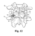
- the threaded shank portions 20 of the bone screws 12 are engaged across the facet joints F of the upper and lower vertebrae V U , V L , with the longitudinal axis L 1 , L 2 of the bone screws 12 arranged in a transverse or X-shaped configuration (when viewed from an anterior-posterior direction).
- the bone screws 12 thereby serve to interconnect or join the upper and lower vertebrae V U , V L .
- the bone screws 12 may be engaged across the facet joints F via other techniques to secure the facet joints F together and to interconnect the upper and lower vertebrae V U , V L .
- fixation techniques are used to treat diseased or injured spinal motion segments.
- this type of treatment may also be done in combination with various types of interbody fusion techniques
- a material may be delivered to the areas adjacent the facet joints F, and more specifically to the areas adjacent the facet capsules defined by the facet joints F.
- Such material may include, for example, bone cement, a bone growth promoting substance such as BMP, or other bio-compatible materials know to those of skill in the art.
- the fenestration openings 32 will be positioned adjacent the facet joints F, and more particularly adjacent the facet capsules.
- material may be delivered through the cannula passage 30 extending through the threaded shank 20 of the screws 12 ( FIGS.
- the fenestration openings 32 are strategically positioned along the distal end portions 12a of the bone screws 12, and more particularly along the distal-most one-third of the bone screws 12, delivery of the material to the facet joints F, and more particularly to the facet capsules, can be accomplished in a controlled and efficient manner.
Claims (23)
- Combinaison d'un ancrage osseux (10) et d'un dispositif (90), l'ancrage osseux (10) comprenant :une partie venant en prise avec l'os (12) ayant une partie d'extrémité proximale (12b) et une partie d'extrémité distale (12a), ladite partie venant en prise avec l'os (12) comprenant un passage de canule (30) s'étendant au moins partiellement au travers depuis ladite partie d'extrémité proximale (12b) vers ladite partie d'extrémité distale (12a) et au moins une ouverture transversale (32) en communication avec ledit passage de canule (30) ; etune partie de guidage allongée (14) comprenant une partie d'arbre (52) s'étendant axialement depuis ladite partie d'extrémité proximale (12b) vers ladite partie venant en prise avec l'os (12) et ayant une extrémité proximale ;le dispositif (90) ayant une partie d'extrémité distale (96) définissant un passage axial (95) de taille plus grande qu'une dimension transversale externe de ladite extrémité proximale de ladite partie d'arbre (52), ladite extrémité proximale de ladite partie d'arbre (52) étant insérée dans et à travers ledit passage axial (95) pour permettre à ladite partie d'extrémité distale (96) dudit dispositif (90) d'être guidée le long de ladite partie d'arbre (52) pour mettre en prise ledit dispositif (90) avec ladite partie d'extrémité proximale (12b) de ladite partie venant en prise avec l'os (12), caractérisé en ce que l'extrémité distale (50) de ladite partie de guidage allongée (14) est en prise avec ladite partie d'extrémité proximale (12b) de ladite partie venant en prise avec l'os (12).
- Combinaison selon la revendication 1, dans laquelle ledit passage de canule (30) étend partiellement à travers ladite partie venant en prise avec l'os (12).
- Combinaison selon la revendication 1, dans laquelle chacune de ladite au moins une ouverture transversale (32) est disposée le long de la partie d'extrémité distale (12a) de ladite partie venant en prise avec l'os (12).
- Combinaison selon la revendication 3, dans laquelle chacune de ladite au moins une ouverture transversale (32) est disposée le long d'un tiers le plus distal de ladite partie venant en prise avec l'os (12).
- Combinaison selon la revendication 1, dans laquelle ladite partie venant en prise avec l'os (12) définit une pluralité de ladite au moins une ouverture transversale (32) en communication avec ledit passage de canule (30).
- Combinaison selon la revendication 1, dans laquelle ladite partie de guidage allongée (14) est configurée pour venir en prise de manière détachable avec ladite partie venant en prise avec l'os (12) pour permettre l'enlèvement sélectif de ladite partie de guidage allongée (14) depuis ladite partie venant en prise avec l'os (12).
- Combinaison selon la revendication 6, dans laquelle ladite partie de guidage allongée est configurée pour venir en prise par filetage avec ladite partie venant en prise avec l'os.
- Combinaison selon la revendication 1, dans laquelle ladite partie de guidage allongée (14) est configurée pour venir en prise avec ladite partie venant en prise avec l'os pour permettre le déplacement angulaire de ladite partie de guidage allongée (14) par rapport à ladite partie venant en prise avec l'os (12).
- Combinaison selon la revendication 1, dans laquelle ladite partie de guidage allongée (14) définit un passage axial (54) s'étendant à travers et communiquant avec ledit passage de canule (30) ; et
comprenant en outre une matière livrée par ledit passage axial (54) dans ledit passage de canule (30) et hors de ladite au moins une ouverture transversale (32). - Combinaison selon la revendication 1, dans laquelle l'une de ladite partie venant en prise avec l'os (12) et de ladite partie de guidage allongée (14) comprend une partie d'extrémité façonnée (50), une autre de ladite partie venant en prise avec l'os et de ladite partie de guidage allongée comprenant un retrait façonné (40) configuré pour recevoir ladite partie d'extrémité façonnée.
- Combinaison selon la revendication 10, dans laquelle ladite partie d'extrémité façonnée (50) et ledit retrait façonné (40) ont chacun une configuration au moins partiellement sphérique.
- Combinaison selon la revendication 10, dans laquelle ladite partie d'extrémité façonnée (50) et ledit retrait façonné (40) ont chacun une configuration au moins partiellement cylindrique.
- Combinaison selon la revendication 10, dans laquelle ladite partie d'extrémité façonnée (50) comprend une boule de forme sphérique et dans laquelle ledit retrait façonné (40) comprend une douille de forme sphérique.
- Combinaison selon la revendication 13, dans laquelle ladite boule de forme sphérique est insérée dans ladite douille de forme sphérique pour mettre en prise de façon détachable ladite partie de guidage allongée (14) avec ladite partie venant en prise avec l'os (12).
- Combinaison selon la revendication 1, comprenant en outre une matière pouvant être délivrée dans ledit passage de canule et hors de ladite moins une ouverture transversale.
- Combinaison selon la revendication 15, dans laquelle ladite matière comprend du ciment osseux.
- Combinaison selon la revendication 15, dans laquelle ladite matière comprend une substance favorisant la croissance osseuse.
- Combinaison selon la revendication 17, dans laquelle ladite substance favorisant la croissance osseuse comprend une protéine morphogénique osseuse.
- Combinaison selon la revendication 15, dans laquelle le dispositif (70) comprend un injecteur adapté pour injecter ladite matière dans ledit passage de canule (30) et hors de ladite au moins une ouverture transversale (32).
- Combinaison selon la revendication 15, dans laquelle le dispositif comprend un élément tubulaire (400) adapté pour amener ladite matière dans ledit passage de canule (330) et hors de ladite au moins une ouverture transversale (332).
- Combinaison selon la revendication 20, dans laquelle ledit élément tubulaire (400) est adapté pour venir en prise de manière filetée avec ladite partie d'extrémité proximale (342b) de ladite partie venant en prise avec l'os (312).
- Combinaison selon la revendication 1, dans laquelle le dispositif comprend un instrument chirurgical.
- Combinaison selon la revendication 1, dans laquelle le dispositif comprend un implant rachidien.
Applications Claiming Priority (2)
| Application Number | Priority Date | Filing Date | Title |
|---|---|---|---|
| US10/429,430 US7354442B2 (en) | 2003-05-05 | 2003-05-05 | Bone anchor and methods of using the same |
| PCT/US2004/014415 WO2004098425A2 (fr) | 2003-05-05 | 2004-05-05 | Ancrage osseux et ses methodes d'utilisation |
Publications (2)
| Publication Number | Publication Date |
|---|---|
| EP1622529A2 EP1622529A2 (fr) | 2006-02-08 |
| EP1622529B1 true EP1622529B1 (fr) | 2011-12-28 |
Family
ID=33416046
Family Applications (1)
| Application Number | Title | Priority Date | Filing Date |
|---|---|---|---|
| EP04751682A Expired - Lifetime EP1622529B1 (fr) | 2003-05-05 | 2004-05-05 | Vis à os avec moyen de guidage d'un tournevis |
Country Status (8)
| Country | Link |
|---|---|
| US (1) | US7354442B2 (fr) |
| EP (1) | EP1622529B1 (fr) |
| JP (1) | JP4597977B2 (fr) |
| CN (1) | CN1805715B (fr) |
| AT (1) | ATE538743T1 (fr) |
| AU (1) | AU2004235821B2 (fr) |
| CA (1) | CA2524797C (fr) |
| WO (1) | WO2004098425A2 (fr) |
Cited By (1)
| Publication number | Priority date | Publication date | Assignee | Title |
|---|---|---|---|---|
| EP3831426A1 (fr) | 2019-12-05 | 2021-06-09 | Heraeus Medical GmbH | Dispositif d'application locale de fluides pharmaceutiques |
Families Citing this family (282)
| Publication number | Priority date | Publication date | Assignee | Title |
|---|---|---|---|---|
| US20050228397A1 (en) * | 1998-08-14 | 2005-10-13 | Malandain Hugues F | Cavity filling device |
| US6887243B2 (en) | 2001-03-30 | 2005-05-03 | Triage Medical, Inc. | Method and apparatus for bone fixation with secondary compression |
| US6511481B2 (en) | 2001-03-30 | 2003-01-28 | Triage Medical, Inc. | Method and apparatus for fixation of proximal femoral fractures |
| US6793678B2 (en) | 2002-06-27 | 2004-09-21 | Depuy Acromed, Inc. | Prosthetic intervertebral motion disc having dampening |
| ES2336551T3 (es) | 2002-07-19 | 2010-04-14 | Interventional Spine, Inc. | Dispositivo de fijacion de la columna vertebral. |
| US7300439B2 (en) * | 2003-06-24 | 2007-11-27 | Depuy Mitek, Inc. | Porous resorbable graft fixation pin |
| US7527611B2 (en) * | 2003-07-15 | 2009-05-05 | Spinal Generations, Llc | Method and device for delivering medicine to bone |
| US8870836B2 (en) | 2003-07-15 | 2014-10-28 | Spinal Generations, Llc | Method and device for delivering medicine to bone |
| US7608062B2 (en) * | 2003-07-15 | 2009-10-27 | Spinal Generations, Llc | Method and device for delivering medicine to bone |
| US7575572B2 (en) * | 2003-07-15 | 2009-08-18 | Spinal Generations, Llc | Method and device for delivering medicine to bone |
| US8062270B2 (en) | 2003-07-15 | 2011-11-22 | Spinal Generations, Llc | Method and device for delivering medicine to bone |
| US7608092B1 (en) | 2004-02-20 | 2009-10-27 | Biomet Sports Medicince, LLC | Method and apparatus for performing meniscus repair |
| DE102004022590A1 (de) * | 2004-05-07 | 2005-12-01 | Feussner, Hubertus, Prof.Dr.med. | Blindniet zur Adaption von biologischem Gewebe und Vorrichtung zum Setzen des selbigen, insbesondere durch den Instrumentenkanal eines Endoskops |
| US8690883B2 (en) * | 2004-06-29 | 2014-04-08 | Spine Wave, Inc. | Articulating injection cannula and seal assembly |
| US7776041B1 (en) * | 2004-07-12 | 2010-08-17 | Biomet Sports Medicine, Llc | Method and apparatus for implanting a suture anchor |
| US8597360B2 (en) | 2004-11-03 | 2013-12-03 | Neuropro Technologies, Inc. | Bone fusion device |
| US8298262B2 (en) | 2006-02-03 | 2012-10-30 | Biomet Sports Medicine, Llc | Method for tissue fixation |
| US8137382B2 (en) | 2004-11-05 | 2012-03-20 | Biomet Sports Medicine, Llc | Method and apparatus for coupling anatomical features |
| US7905904B2 (en) | 2006-02-03 | 2011-03-15 | Biomet Sports Medicine, Llc | Soft tissue repair device and associated methods |
| US9017381B2 (en) | 2007-04-10 | 2015-04-28 | Biomet Sports Medicine, Llc | Adjustable knotless loops |
| US7905903B2 (en) | 2006-02-03 | 2011-03-15 | Biomet Sports Medicine, Llc | Method for tissue fixation |
| US9801708B2 (en) | 2004-11-05 | 2017-10-31 | Biomet Sports Medicine, Llc | Method and apparatus for coupling soft tissue to a bone |
| US8303604B2 (en) | 2004-11-05 | 2012-11-06 | Biomet Sports Medicine, Llc | Soft tissue repair device and method |
| US8361113B2 (en) | 2006-02-03 | 2013-01-29 | Biomet Sports Medicine, Llc | Method and apparatus for coupling soft tissue to a bone |
| US8088130B2 (en) | 2006-02-03 | 2012-01-03 | Biomet Sports Medicine, Llc | Method and apparatus for coupling soft tissue to a bone |
| US7658751B2 (en) | 2006-09-29 | 2010-02-09 | Biomet Sports Medicine, Llc | Method for implanting soft tissue |
| US7909851B2 (en) | 2006-02-03 | 2011-03-22 | Biomet Sports Medicine, Llc | Soft tissue repair device and associated methods |
| US8128658B2 (en) | 2004-11-05 | 2012-03-06 | Biomet Sports Medicine, Llc | Method and apparatus for coupling soft tissue to bone |
| US7857830B2 (en) | 2006-02-03 | 2010-12-28 | Biomet Sports Medicine, Llc | Soft tissue repair and conduit device |
| US20060189993A1 (en) | 2004-11-09 | 2006-08-24 | Arthrotek, Inc. | Soft tissue conduit device |
| US8118836B2 (en) | 2004-11-05 | 2012-02-21 | Biomet Sports Medicine, Llc | Method and apparatus for coupling soft tissue to a bone |
| US7749250B2 (en) | 2006-02-03 | 2010-07-06 | Biomet Sports Medicine, Llc | Soft tissue repair assembly and associated method |
| US8840645B2 (en) | 2004-11-05 | 2014-09-23 | Biomet Sports Medicine, Llc | Method and apparatus for coupling soft tissue to a bone |
| US8034090B2 (en) | 2004-11-09 | 2011-10-11 | Biomet Sports Medicine, Llc | Tissue fixation device |
| US8998949B2 (en) | 2004-11-09 | 2015-04-07 | Biomet Sports Medicine, Llc | Soft tissue conduit device |
| US7914539B2 (en) | 2004-11-09 | 2011-03-29 | Biomet Sports Medicine, Llc | Tissue fixation device |
| US20060111779A1 (en) * | 2004-11-22 | 2006-05-25 | Orthopedic Development Corporation, A Florida Corporation | Minimally invasive facet joint fusion |
| US8986345B2 (en) | 2004-12-07 | 2015-03-24 | Biomet Sports Medicine, Llc | Expanding suture anchor having an actuator pin |
| US7572283B1 (en) * | 2004-12-07 | 2009-08-11 | Biomet Sports Medicine, Llc | Soft tissue rivet and method of use |
| US7976565B1 (en) | 2004-12-07 | 2011-07-12 | Biomet Sports Medicine, Llc | Expanding suture anchor having an actuator pin |
| WO2006062518A2 (fr) | 2004-12-08 | 2006-06-15 | Interpore Spine Ltd. | Composite a phase continue pour reparation musculosquelettique |
| US7857832B2 (en) | 2004-12-08 | 2010-12-28 | Interventional Spine, Inc. | Method and apparatus for spinal stabilization |
| US7648523B2 (en) | 2004-12-08 | 2010-01-19 | Interventional Spine, Inc. | Method and apparatus for spinal stabilization |
| US8535357B2 (en) * | 2004-12-09 | 2013-09-17 | Biomet Sports Medicine, Llc | Continuous phase compositions for ACL repair |
| US20070299450A1 (en) * | 2004-12-31 | 2007-12-27 | Ji-Hoon Her | Pedicle Screw and Device for Injecting Bone Cement into Bone |
| US9326800B2 (en) * | 2005-03-24 | 2016-05-03 | DePuy Synthes Products, Inc. | Device for the cement augmentation of bone implants |
| US11801043B2 (en) | 2005-03-30 | 2023-10-31 | Arthrex, Inc. | Suture anchor for knotless fixation of tissue |
| US20090187216A1 (en) * | 2006-05-18 | 2009-07-23 | Arthrex, Inc. | Fenestrated swivel anchor for knotless fixation of tissue |
| US20090192546A1 (en) | 2005-03-30 | 2009-07-30 | Reinhold Schmieding | Fenestrated suture anchor and method for knotless fixation of tissue |
| US20060241758A1 (en) * | 2005-04-20 | 2006-10-26 | Sdgi Holdings, Inc. | Facet spacers |
| EP1726273A1 (fr) * | 2005-05-24 | 2006-11-29 | Zimmer GmbH | Prothèse pour l'articulation de la hanche |
| US20070055257A1 (en) * | 2005-06-30 | 2007-03-08 | Alex Vaccaro | Cannulated screw access system |
| US8562689B2 (en) * | 2005-10-13 | 2013-10-22 | Aptis Medical, Llc | Wrist prosthesis |
| US8100946B2 (en) | 2005-11-21 | 2012-01-24 | Synthes Usa, Llc | Polyaxial bone anchors with increased angulation |
| US20070161985A1 (en) * | 2005-12-05 | 2007-07-12 | Kentomia, Llc . | Screws configured to engage bones, and methods of attaching implants to skeletal regions |
| PT103404A (pt) * | 2005-12-21 | 2007-06-29 | Univ Aveiro | Implante ósseo de fixação combinada |
| US20070156145A1 (en) * | 2005-12-30 | 2007-07-05 | Kentomia, Llc | Therapeutic constructions, spinal plates, cervical plates, hooks and screws |
| US20070179609A1 (en) * | 2006-01-27 | 2007-08-02 | Medicinelodge, Inc. | Therapeutic agent eluding implant with percutaneous supply |
| US9149267B2 (en) | 2006-02-03 | 2015-10-06 | Biomet Sports Medicine, Llc | Method and apparatus for coupling soft tissue to a bone |
| US8562647B2 (en) | 2006-09-29 | 2013-10-22 | Biomet Sports Medicine, Llc | Method and apparatus for securing soft tissue to bone |
| US8771352B2 (en) | 2011-05-17 | 2014-07-08 | Biomet Sports Medicine, Llc | Method and apparatus for tibial fixation of an ACL graft |
| US8936621B2 (en) | 2006-02-03 | 2015-01-20 | Biomet Sports Medicine, Llc | Method and apparatus for forming a self-locking adjustable loop |
| US8652172B2 (en) | 2006-02-03 | 2014-02-18 | Biomet Sports Medicine, Llc | Flexible anchors for tissue fixation |
| US8574235B2 (en) | 2006-02-03 | 2013-11-05 | Biomet Sports Medicine, Llc | Method for trochanteric reattachment |
| US11311287B2 (en) | 2006-02-03 | 2022-04-26 | Biomet Sports Medicine, Llc | Method for tissue fixation |
| US9271713B2 (en) | 2006-02-03 | 2016-03-01 | Biomet Sports Medicine, Llc | Method and apparatus for tensioning a suture |
| US11259792B2 (en) | 2006-02-03 | 2022-03-01 | Biomet Sports Medicine, Llc | Method and apparatus for coupling anatomical features |
| US9538998B2 (en) | 2006-02-03 | 2017-01-10 | Biomet Sports Medicine, Llc | Method and apparatus for fracture fixation |
| US8968364B2 (en) | 2006-02-03 | 2015-03-03 | Biomet Sports Medicine, Llc | Method and apparatus for fixation of an ACL graft |
| US7959650B2 (en) | 2006-09-29 | 2011-06-14 | Biomet Sports Medicine, Llc | Adjustable knotless loops |
| US8506597B2 (en) | 2011-10-25 | 2013-08-13 | Biomet Sports Medicine, Llc | Method and apparatus for interosseous membrane reconstruction |
| US8652171B2 (en) | 2006-02-03 | 2014-02-18 | Biomet Sports Medicine, Llc | Method and apparatus for soft tissue fixation |
| US8562645B2 (en) | 2006-09-29 | 2013-10-22 | Biomet Sports Medicine, Llc | Method and apparatus for forming a self-locking adjustable loop |
| US8251998B2 (en) | 2006-08-16 | 2012-08-28 | Biomet Sports Medicine, Llc | Chondral defect repair |
| US8597327B2 (en) | 2006-02-03 | 2013-12-03 | Biomet Manufacturing, Llc | Method and apparatus for sternal closure |
| US8801783B2 (en) | 2006-09-29 | 2014-08-12 | Biomet Sports Medicine, Llc | Prosthetic ligament system for knee joint |
| US9078644B2 (en) | 2006-09-29 | 2015-07-14 | Biomet Sports Medicine, Llc | Fracture fixation device |
| US10517587B2 (en) | 2006-02-03 | 2019-12-31 | Biomet Sports Medicine, Llc | Method and apparatus for forming a self-locking adjustable loop |
| US7520888B2 (en) * | 2006-02-14 | 2009-04-21 | Warsaw Orthopedic, Inc. | Treatment of the vertebral column |
| CA2648283A1 (fr) * | 2006-04-07 | 2007-10-18 | Societe De Commercialisation Des Produits De La Recherche Appliquee Socp Ra Sciences Et Genie S.E.C. | Systeme integre de distribution de ciment acrylique pour des procedures et methodes d'augmentation osseuse |
| US9867646B2 (en) | 2006-04-07 | 2018-01-16 | Gamal Baroud | Integrated cement delivery system for bone augmentation procedures and methods |
| US8372126B2 (en) * | 2006-04-21 | 2013-02-12 | Warsaw Orthopedic, Inc. | Surgical fasteners with mechanical and osteogenic fixation means |
| US8821506B2 (en) * | 2006-05-11 | 2014-09-02 | Michael David Mitchell | Bone screw |
| AU2007202269B2 (en) | 2006-05-18 | 2013-01-24 | Arthrex, Inc. | Swivel anchor and method for knotless fixation of tissue |
| TWM306498U (en) * | 2006-08-10 | 2007-02-21 | Shih-Tseng Lee | Securing member, expansion anchroing screw set |
| AU2007285791A1 (en) | 2006-08-17 | 2008-02-21 | Synthes Gmbh | Push-off driver and method for inserting bone screws |
| US8500818B2 (en) | 2006-09-29 | 2013-08-06 | Biomet Manufacturing, Llc | Knee prosthesis assembly with ligament link |
| US9918826B2 (en) | 2006-09-29 | 2018-03-20 | Biomet Sports Medicine, Llc | Scaffold for spring ligament repair |
| US8672969B2 (en) | 2006-09-29 | 2014-03-18 | Biomet Sports Medicine, Llc | Fracture fixation device |
| US11259794B2 (en) | 2006-09-29 | 2022-03-01 | Biomet Sports Medicine, Llc | Method for implanting soft tissue |
| US8167906B2 (en) * | 2006-11-01 | 2012-05-01 | Depuy Mitek, Inc. | Suture anchor with pulley |
| US7931651B2 (en) | 2006-11-17 | 2011-04-26 | Wake Lake University Health Sciences | External fixation assembly and method of use |
| WO2008070863A2 (fr) | 2006-12-07 | 2008-06-12 | Interventional Spine, Inc. | Implant intervertébral |
| US8403965B2 (en) * | 2007-01-29 | 2013-03-26 | Polaris Biotechnology, Inc. | Vertebra attachment method and system |
| US20090036894A1 (en) * | 2007-01-29 | 2009-02-05 | Polaris Biotechnology, Inc. | Method of treating a neurological condition through correction and stabilization of the clivo-axial angle |
| US8182511B2 (en) | 2007-01-29 | 2012-05-22 | Polaris Biotechnology, Inc. | Craniospinal fusion method and apparatus |
| US8556939B2 (en) * | 2008-01-08 | 2013-10-15 | Fraser Cummins Henderson | Mathematical relationship of strain, neurological dysfunction and abnormal behavior resulting from neurological dysfunction of the brainstem |
| US9827023B2 (en) | 2007-01-29 | 2017-11-28 | Life Spine, Inc. | Craniospinal fusion method and apparatus |
| US8043342B2 (en) * | 2007-01-29 | 2011-10-25 | Polaris Biotechnology, Inc. | Craniospinal fusion method and apparatus |
| US8133261B2 (en) | 2007-02-26 | 2012-03-13 | Depuy Spine, Inc. | Intra-facet fixation device and method of use |
| US20080221681A1 (en) * | 2007-03-09 | 2008-09-11 | Warsaw Orthopedic, Inc. | Methods for Improving Fatigue Performance of Implants With Osteointegrating Coatings |
| US8043334B2 (en) | 2007-04-13 | 2011-10-25 | Depuy Spine, Inc. | Articulating facet fusion screw |
| US8894685B2 (en) | 2007-04-13 | 2014-11-25 | DePuy Synthes Products, LLC | Facet fixation and fusion screw and washer assembly and method of use |
| US8197513B2 (en) | 2007-04-13 | 2012-06-12 | Depuy Spine, Inc. | Facet fixation and fusion wedge and method of use |
| US8551124B2 (en) | 2007-04-20 | 2013-10-08 | Stryker Trauma Gmbh | Implantation pin, fixation device and method for implanting the implantation pin |
| US7794484B2 (en) | 2007-05-07 | 2010-09-14 | Biomet Sports Medicine, Llc | Fixation device for delivery of biological material between soft tissue and bone |
| US7998176B2 (en) | 2007-06-08 | 2011-08-16 | Interventional Spine, Inc. | Method and apparatus for spinal stabilization |
| US8900307B2 (en) | 2007-06-26 | 2014-12-02 | DePuy Synthes Products, LLC | Highly lordosed fusion cage |
| US10758283B2 (en) * | 2016-08-11 | 2020-09-01 | Mighty Oak Medical, Inc. | Fixation devices having fenestrations and methods for using the same |
| CN102512229B (zh) * | 2007-07-20 | 2016-01-20 | 新特斯有限责任公司 | 多轴骨固定元件 |
| US9439681B2 (en) | 2007-07-20 | 2016-09-13 | DePuy Synthes Products, Inc. | Polyaxial bone fixation element |
| US8702754B2 (en) | 2007-09-14 | 2014-04-22 | Depuy Mitek, Llc | Methods for anchoring suture to bone |
| US20090138092A1 (en) * | 2007-11-28 | 2009-05-28 | Johnston Brent W | Therapeutic Structures for Utilization in Temporomandibular Joint Replacement Systems |
| WO2009089395A2 (fr) * | 2008-01-08 | 2009-07-16 | Polaris Biotechnology, Inc. | Appareil d'ostéointégration |
| WO2009092102A1 (fr) | 2008-01-17 | 2009-07-23 | Synthes Usa, Llc | Implant intervertébral extensible et son procédé de fabrication associé |
| US8333804B1 (en) | 2008-03-27 | 2012-12-18 | Spinelogik, Inc. | Intervertebral fusion device and method of use |
| US8313528B1 (en) | 2008-03-27 | 2012-11-20 | Spinelogik, Inc. | Intervertebral fusion device and method of use |
| WO2009124269A1 (fr) | 2008-04-05 | 2009-10-08 | Synthes Usa, Llc | Implant intervertébral extensible |
| US20090264895A1 (en) * | 2008-04-22 | 2009-10-22 | Warsaw Orthopedic, Inc. | Systems and methods for implanting a bone fastener and delivering a bone filling material |
| EP2111811B1 (fr) * | 2008-04-22 | 2011-06-15 | BIEDERMANN MOTECH GmbH | Instrument pour assembler un dispositif d'ancrage osseux |
| US8257407B2 (en) * | 2008-04-23 | 2012-09-04 | Aryan Henry E | Bone plate system and method |
| DE102008024440B4 (de) * | 2008-05-13 | 2022-06-09 | Aesculap Ag | Implantat und Implantationssystem |
| EP2328492B1 (fr) * | 2008-06-06 | 2018-03-28 | Providence Medical Technology, Inc. | Implants pour articulation facettaire et outils de mise en place |
| ES2585152T3 (es) | 2008-07-01 | 2016-10-04 | Biedermann Technologies Gmbh & Co. Kg | Anclaje óseo canulado con elemento tapón y herramienta para insertar el elemento tapón en el anclaje óseo |
| US9616205B2 (en) * | 2008-08-13 | 2017-04-11 | Smed-Ta/Td, Llc | Drug delivery implants |
| EP2355725B1 (fr) | 2008-09-05 | 2017-03-08 | Synthes GmbH | Ensemble fixation osseuse |
| ES2384311T3 (es) | 2008-09-12 | 2012-07-03 | Synthes Gmbh | Sistema de fijación para estabilización y guiado de columna vertebral |
| CA2738659A1 (fr) | 2008-09-29 | 2010-04-01 | Synthes Usa, Llc | Vis polyaxiale a chargement par le bas et ensemble tige |
| ES2484465T3 (es) * | 2008-10-10 | 2014-08-11 | Stryker Trauma Gmbh | Kit de perno de implante y método para implantar un perno de implante |
| JP5804325B2 (ja) * | 2008-10-30 | 2015-11-04 | デピュイ・シンセス・プロダクツ・インコーポレイテッド | 骨アンカーに骨セメントを送達するためのシステム及び方法 |
| CA2742399A1 (fr) | 2008-11-03 | 2010-06-03 | Dustin M. Harvey | Ensemble fixation osseuse plane |
| US9433436B2 (en) | 2008-11-20 | 2016-09-06 | Bioactive Surgical Inc. | Therapeutic material delivery system for tissue voids and cannulated implants |
| US8317799B2 (en) * | 2008-11-20 | 2012-11-27 | Bioactive Surgical, Inc. | Therapeutic material delivery system for tissue voids and cannulated implants |
| US11406791B2 (en) | 2009-04-03 | 2022-08-09 | Scientia Vascular, Inc. | Micro-fabricated guidewire devices having varying diameters |
| FR2941859B1 (fr) | 2009-02-09 | 2012-04-06 | Memometal Technologies | Vis d'osteosynthese. |
| US9526620B2 (en) | 2009-03-30 | 2016-12-27 | DePuy Synthes Products, Inc. | Zero profile spinal fusion cage |
| EP2236101B1 (fr) | 2009-04-03 | 2015-07-08 | Stryker Trauma GmbH | Vis sonique |
| EP2419031B1 (fr) | 2009-04-15 | 2016-11-30 | Synthes GmbH | Connecteur de révision pour constructions rachidiennes |
| CA2759445A1 (fr) * | 2009-04-20 | 2010-10-28 | Osteo Innovations Llc | Systeme et procede pour vis a os a remplissage automatique |
| US8460305B2 (en) * | 2009-05-21 | 2013-06-11 | Christopher S. Jordan | Cannulated surgical screw bone filler adapter |
| US8231632B1 (en) * | 2009-05-21 | 2012-07-31 | Jordan Christopher S | Cannulated surgical screw bone filler adapter |
| US8343227B2 (en) | 2009-05-28 | 2013-01-01 | Biomet Manufacturing Corp. | Knee prosthesis assembly with ligament link |
| DE102010016812A1 (de) * | 2009-06-08 | 2011-03-17 | Z.-Medical Gmbh & Co. Kg | Knochenschraube |
| BRPI1012921A2 (pt) | 2009-06-17 | 2016-04-05 | Synthes Gmbh | conector de revisão para construção espinhal |
| US8574273B2 (en) | 2009-09-09 | 2013-11-05 | Innovision, Inc. | Bone screws and methods of use thereof |
| US20170238984A1 (en) * | 2009-09-18 | 2017-08-24 | Spinal Surgical Strategies, Llc | Bone graft delivery device with positioning handle |
| US8747411B2 (en) * | 2009-09-30 | 2014-06-10 | Michael David Mitchell | Fluid delivery and bone screw driver apparatus |
| US20110082506A1 (en) * | 2009-10-02 | 2011-04-07 | Spinefrontier, Inc | Cervical plate assembly |
| BR112012010903B1 (pt) * | 2009-11-09 | 2020-10-27 | Spinewelding Ag | dispositivo médico |
| EP2498687B1 (fr) | 2009-11-10 | 2020-06-17 | Smith & Nephew, Inc. | Ensemble d'ancrage de suture de blocage |
| US20110118783A1 (en) * | 2009-11-16 | 2011-05-19 | Spartek Medical, Inc. | Load-sharing bone anchor having a flexible post and method for dynamic stabilization of the spine |
| US9763720B2 (en) | 2009-11-17 | 2017-09-19 | Wright Medical Technology, Inc. | Method and device for insertion of orthopedic fixation pin with blind hole |
| EP2329780B1 (fr) | 2009-12-03 | 2013-02-20 | Biedermann Technologies GmbH & Co. KG | Vis à os |
| US9393129B2 (en) | 2009-12-10 | 2016-07-19 | DePuy Synthes Products, Inc. | Bellows-like expandable interbody fusion cage |
| US9427324B1 (en) | 2010-02-22 | 2016-08-30 | Spinelogik, Inc. | Intervertebral fusion device and method of use |
| EP2712564B1 (fr) * | 2010-02-26 | 2017-04-05 | Biedermann Technologies GmbH & Co. KG | Vis à os |
| US8500819B2 (en) * | 2010-03-05 | 2013-08-06 | Biomet Manufacturing, Llc | Drug delivery and diagnostic system for orthopedic implants |
| US8945224B2 (en) * | 2010-03-18 | 2015-02-03 | Warsaw, Orthopedic, Inc. | Sacro-iliac implant system, method and apparatus |
| US8979860B2 (en) | 2010-06-24 | 2015-03-17 | DePuy Synthes Products. LLC | Enhanced cage insertion device |
| US9592063B2 (en) | 2010-06-24 | 2017-03-14 | DePuy Synthes Products, Inc. | Universal trial for lateral cages |
| WO2012003175A1 (fr) | 2010-06-29 | 2012-01-05 | Synthes Usa, Llc | Implant intervertébral capable de distraction |
| US9044277B2 (en) | 2010-07-12 | 2015-06-02 | DePuy Synthes Products, Inc. | Pedicular facet fusion screw with plate |
| US20120029562A1 (en) * | 2010-07-27 | 2012-02-02 | Rockford Orthopaedic Sports Medicine Services, Llc | Biologic anchor delivery system |
| US9402732B2 (en) | 2010-10-11 | 2016-08-02 | DePuy Synthes Products, Inc. | Expandable interspinous process spacer implant |
| US20120116459A1 (en) * | 2010-11-02 | 2012-05-10 | Nottmeier Eric W | Bone Fixation Device and Methods for Use Thereof |
| US8409257B2 (en) | 2010-11-10 | 2013-04-02 | Warsaw Othopedic, Inc. | Systems and methods for facet joint stabilization |
| US9358122B2 (en) | 2011-01-07 | 2016-06-07 | K2M, Inc. | Interbody spacer |
| US8795334B2 (en) | 2011-01-28 | 2014-08-05 | Smith & Nephew, Inc. | Tissue repair |
| BR112013019735A2 (pt) * | 2011-02-03 | 2016-10-25 | Alphatec Spine Inc | dispositivo de entrega de material para um parafuso de osso |
| WO2012109748A1 (fr) * | 2011-02-14 | 2012-08-23 | The Royal Institution For The Advancement Of Learning / Mcgill University | Systèmes et procédés pour injecter du fluide dans un os et pour insérer des vis à os, et vis à os pour ceux-ci |
| US9265620B2 (en) * | 2011-03-18 | 2016-02-23 | Raed M. Ali, M.D., Inc. | Devices and methods for transpedicular stabilization of the spine |
| US8790375B2 (en) * | 2011-03-18 | 2014-07-29 | Raed M. Ali, M.D., Inc. | Transpedicular access to intervertebral spaces and related spinal fusion systems and methods |
| WO2012142032A1 (fr) * | 2011-04-10 | 2012-10-18 | The Cleveland Clinic Foundation | Procédés et dispositifs pour la préparation d'os |
| US9427268B2 (en) * | 2011-04-20 | 2016-08-30 | Chongqing Runze Pharmaceutical Co., Ltd. | Porous tantalum rod |
| US10292830B2 (en) | 2011-08-09 | 2019-05-21 | Neuropro Technologies, Inc. | Bone fusion device, system and method |
| WO2013023098A1 (fr) | 2011-08-09 | 2013-02-14 | Neuropro Spinal Jaxx Inc. | Dispositif, appareil et procédé de fusion osseuse |
| US9155580B2 (en) | 2011-08-25 | 2015-10-13 | Medos International Sarl | Multi-threaded cannulated bone anchors |
| US9084647B2 (en) * | 2011-10-12 | 2015-07-21 | Globus Medical, Inc. | Screw with anchor features |
| US20130110115A1 (en) * | 2011-10-26 | 2013-05-02 | Medulaplasty LLC | Minimally invasive method and devices for repairing loosened prosthetic implants |
| US9357991B2 (en) | 2011-11-03 | 2016-06-07 | Biomet Sports Medicine, Llc | Method and apparatus for stitching tendons |
| US9381013B2 (en) | 2011-11-10 | 2016-07-05 | Biomet Sports Medicine, Llc | Method for coupling soft tissue to a bone |
| US9370350B2 (en) | 2011-11-10 | 2016-06-21 | Biomet Sports Medicine, Llc | Apparatus for coupling soft tissue to a bone |
| US9357992B2 (en) | 2011-11-10 | 2016-06-07 | Biomet Sports Medicine, Llc | Method for coupling soft tissue to a bone |
| US9259217B2 (en) | 2012-01-03 | 2016-02-16 | Biomet Manufacturing, Llc | Suture Button |
| US9687285B2 (en) | 2012-01-25 | 2017-06-27 | Spectrum Spine Ip Holdings, Llc | Fenestrated bone screws and methods of bone fastening and stabilization |
| US8641770B2 (en) | 2012-01-26 | 2014-02-04 | Aptis Medical, Llc | Prosthesis for the basal joint of the thumb |
| US20130211466A1 (en) * | 2012-02-15 | 2013-08-15 | Warsaw Orthopedic, Inc. | Bone fastener and methods of use |
| US20130245703A1 (en) * | 2012-03-02 | 2013-09-19 | Interventional Spine, Inc. | Method and apparatus for sacroiliac joint fixation |
| US9387025B2 (en) | 2012-04-04 | 2016-07-12 | Smith & Nephew, Inc. | Bone screw and self-retaining driver |
| US9532883B2 (en) | 2012-04-13 | 2017-01-03 | Neuropro Technologies, Inc. | Bone fusion device |
| US9173692B1 (en) * | 2012-06-15 | 2015-11-03 | Stc.Unm | Composite metal and bone orthopedic fixation devices |
| US8940052B2 (en) | 2012-07-26 | 2015-01-27 | DePuy Synthes Products, LLC | Expandable implant |
| US9603644B2 (en) * | 2012-08-07 | 2017-03-28 | Spinal Generations, Llc | Methods and devices for delivery of medicine to bone |
| US9295488B2 (en) | 2012-08-09 | 2016-03-29 | Wilson T. Asfora | Joint fusion |
| US20140067069A1 (en) | 2012-08-30 | 2014-03-06 | Interventional Spine, Inc. | Artificial disc |
| ES1077793Y (es) * | 2012-09-19 | 2013-01-10 | Servocad Microtronics S L | Herramienta mecanica |
| US8986327B2 (en) | 2012-10-18 | 2015-03-24 | Smith & Nephew, Inc. | Flexible anchor delivery system |
| CN102949234A (zh) * | 2012-11-20 | 2013-03-06 | 苏州艾迪尔医疗器械有限公司 | 一种多轴万向钉 |
| CN103892899A (zh) * | 2012-12-26 | 2014-07-02 | 北京爱康宜诚医疗器材股份有限公司 | 定向改锥 |
| US9326801B2 (en) * | 2013-01-08 | 2016-05-03 | Nicholas Poulos | Fenestrated bone screw and method of injecting bone cement into bone structure |
| KR101427511B1 (ko) | 2013-01-14 | 2014-08-07 | 전북대학교산학협력단 | 정형외과용 고정기기 |
| US10076369B2 (en) | 2013-01-16 | 2018-09-18 | Spinefrontier, Inc | Bone fastener for a spinal fixation assembly |
| US9522070B2 (en) | 2013-03-07 | 2016-12-20 | Interventional Spine, Inc. | Intervertebral implant |
| US9757119B2 (en) | 2013-03-08 | 2017-09-12 | Biomet Sports Medicine, Llc | Visual aid for identifying suture limbs arthroscopically |
| US9028464B2 (en) * | 2013-03-08 | 2015-05-12 | Kyphon Saul | Bone fracture reduction system and methods of using the same |
| US11304818B2 (en) | 2013-03-13 | 2022-04-19 | Life Spine, Inc. | Expandable spinal interbody assembly |
| US10426632B2 (en) * | 2013-03-13 | 2019-10-01 | Life Spine, Inc. | Expandable spinal interbody assembly |
| US10687962B2 (en) | 2013-03-14 | 2020-06-23 | Raed M. Ali, M.D., Inc. | Interbody fusion devices, systems and methods |
| EP2967909A4 (fr) | 2013-03-14 | 2016-10-05 | Raed M Ali M D Inc | Dispositifs, systèmes et procédés de fusion inter-corps latérale |
| US9918827B2 (en) | 2013-03-14 | 2018-03-20 | Biomet Sports Medicine, Llc | Scaffold for spring ligament repair |
| US10098757B2 (en) | 2013-03-15 | 2018-10-16 | Neuropro Technologies Inc. | Bodiless bone fusion device, apparatus and method |
| US10548651B2 (en) * | 2013-03-15 | 2020-02-04 | Nicholas Poulos | Self-drilling, self-tapping bone screw |
| US9993276B2 (en) | 2013-03-15 | 2018-06-12 | Innovision, Inc. | Bone screws and methods of use thereof |
| US9522028B2 (en) | 2013-07-03 | 2016-12-20 | Interventional Spine, Inc. | Method and apparatus for sacroiliac joint fixation |
| DE102013109895A1 (de) * | 2013-09-10 | 2015-03-12 | Aesculap Ag | Medizinisches Instrument |
| US10136886B2 (en) | 2013-12-20 | 2018-11-27 | Biomet Sports Medicine, Llc | Knotless soft tissue devices and techniques |
| US10653470B2 (en) | 2014-02-19 | 2020-05-19 | Spinal Generation, LLC | Compressible mixing and delivery system for medical substances |
| US9717491B2 (en) | 2014-03-10 | 2017-08-01 | Biomet Sports Medicine, Llc | Method and apparatus for coupling soft tissue to bone |
| US9615822B2 (en) | 2014-05-30 | 2017-04-11 | Biomet Sports Medicine, Llc | Insertion tools and method for soft anchor |
| US9700291B2 (en) | 2014-06-03 | 2017-07-11 | Biomet Sports Medicine, Llc | Capsule retractor |
| DE202014006372U1 (de) * | 2014-08-05 | 2014-08-22 | Medartis Ag | Schraube mit Einbringpfosten |
| US10039543B2 (en) | 2014-08-22 | 2018-08-07 | Biomet Sports Medicine, Llc | Non-sliding soft anchor |
| WO2016030815A1 (fr) * | 2014-08-25 | 2016-03-03 | P Dr Kannan | Dispositif d'administration locale pour effet thérapeutique ciblé |
| US9615863B2 (en) | 2014-10-22 | 2017-04-11 | Spinal Generations, Llc | Multichannel cannula for kyphoplasty and method of use |
| WO2016127522A1 (fr) * | 2015-02-09 | 2016-08-18 | 张英泽 | Appareil poreux de fixation interne bionique pour favoriser la guérison d'une fracture |
| US9955980B2 (en) | 2015-02-24 | 2018-05-01 | Biomet Sports Medicine, Llc | Anatomic soft tissue repair |
| US11426290B2 (en) | 2015-03-06 | 2022-08-30 | DePuy Synthes Products, Inc. | Expandable intervertebral implant, system, kit and method |
| US9974534B2 (en) | 2015-03-31 | 2018-05-22 | Biomet Sports Medicine, Llc | Suture anchor with soft anchor of electrospun fibers |
| CN104799923A (zh) * | 2015-04-30 | 2015-07-29 | 中国人民解放军第二军医大学 | 用于椎体压缩性骨折的撑开植骨器 |
| DE202015102342U1 (de) | 2015-05-07 | 2015-05-28 | Wilhelm Ungeheuer Söhne GmbH | Befestigungseinrichtung |
| US10743927B1 (en) * | 2015-06-02 | 2020-08-18 | Pmt Corporation | Anchor bolt driver device |
| US9913727B2 (en) | 2015-07-02 | 2018-03-13 | Medos International Sarl | Expandable implant |
| RU2767702C2 (ru) * | 2015-10-26 | 2022-03-18 | Леон Е. ПОПОВИЦ | Суставной имплантат, восполняющий циркуляцию крови |
| CN106923899A (zh) * | 2015-12-29 | 2017-07-07 | 肖珍云 | 一种骨科锁定螺钉 |
| DE102016106308A1 (de) * | 2016-04-06 | 2017-10-12 | Aesculap Ag | Knochenimplantat mit Versatz im Injektionskanal sowie Implantationswerkzeug hierfür |
| CN109688981A (zh) | 2016-06-28 | 2019-04-26 | Eit 新兴移植技术股份有限公司 | 可扩张的、角度可调整的椎间笼 |
| EP3474782A2 (fr) | 2016-06-28 | 2019-05-01 | Eit Emerging Implant Technologies GmbH | Cages intervertébrales articulées à expansion et réglage angulaire |
| US11207502B2 (en) | 2016-07-18 | 2021-12-28 | Scientia Vascular, Llc | Guidewire devices having shapeable tips and bypass cuts |
| US11052228B2 (en) | 2016-07-18 | 2021-07-06 | Scientia Vascular, Llc | Guidewire devices having shapeable tips and bypass cuts |
| US10052140B2 (en) | 2016-10-05 | 2018-08-21 | Stryker European Holdings I, Llc | Apparatus and method for fenestrated screw augmentation |
| US10667923B2 (en) | 2016-10-31 | 2020-06-02 | Warsaw Orthopedic, Inc. | Sacro-iliac joint implant system and method |
| US10537436B2 (en) | 2016-11-01 | 2020-01-21 | DePuy Synthes Products, Inc. | Curved expandable cage |
| US10888433B2 (en) | 2016-12-14 | 2021-01-12 | DePuy Synthes Products, Inc. | Intervertebral implant inserter and related methods |
| US11452541B2 (en) | 2016-12-22 | 2022-09-27 | Scientia Vascular, Inc. | Intravascular device having a selectively deflectable tip |
| US10213321B2 (en) | 2017-01-18 | 2019-02-26 | Neuropro Technologies, Inc. | Bone fusion system, device and method including delivery apparatus |
| US10729560B2 (en) | 2017-01-18 | 2020-08-04 | Neuropro Technologies, Inc. | Bone fusion system, device and method including an insertion instrument |
| US10973657B2 (en) * | 2017-01-18 | 2021-04-13 | Neuropro Technologies, Inc. | Bone fusion surgical system and method |
| US10111760B2 (en) | 2017-01-18 | 2018-10-30 | Neuropro Technologies, Inc. | Bone fusion system, device and method including a measuring mechanism |
| US10398563B2 (en) | 2017-05-08 | 2019-09-03 | Medos International Sarl | Expandable cage |
| EP3624708A1 (fr) | 2017-05-19 | 2020-03-25 | Providence Medical Technology, Inc. | Système de pose de fixation vertébrale et d'accès à celle-ci |
| JP2020521552A (ja) | 2017-05-26 | 2020-07-27 | サイエンティア・バスキュラー・エルエルシー | 非らせんカット配列を有する微細加工医療デバイス |
| US10856922B2 (en) * | 2017-06-07 | 2020-12-08 | Warsaw Orthopedic, Inc. | Spinal implant system and method |
| US11344424B2 (en) | 2017-06-14 | 2022-05-31 | Medos International Sarl | Expandable intervertebral implant and related methods |
| US10940016B2 (en) | 2017-07-05 | 2021-03-09 | Medos International Sarl | Expandable intervertebral fusion cage |
| US11033403B2 (en) | 2017-07-10 | 2021-06-15 | Life Spine, Inc. | Expandable implant assembly |
| US11896494B2 (en) | 2017-07-10 | 2024-02-13 | Life Spine, Inc. | Expandable implant assembly |
| US10603054B2 (en) | 2017-10-31 | 2020-03-31 | Sicage Llc | Parallel guide for surgical implants |
| US10792053B2 (en) | 2017-10-31 | 2020-10-06 | Sicage Llc | Press system for setting a surgical device |
| USD847336S1 (en) | 2017-10-31 | 2019-04-30 | Sicage Llc | Parallel surgical guide spacer |
| USD847994S1 (en) | 2017-10-31 | 2019-05-07 | Sicage Llc | Bone screw |
| USD850616S1 (en) | 2017-10-31 | 2019-06-04 | Sicage Llc | Parallel surgical guide spacer |
| USD904615S1 (en) | 2017-10-31 | 2020-12-08 | Sicage Llc | Bone screw |
| US10631905B2 (en) | 2017-10-31 | 2020-04-28 | Sicage Llc | Bone cage with helically arranged fenestrations |
| WO2019136263A1 (fr) | 2018-01-04 | 2019-07-11 | Providence Medical Technology, Inc. | Vis à facettes et dispositif de pose |
| US11305095B2 (en) | 2018-02-22 | 2022-04-19 | Scientia Vascular, Llc | Microfabricated catheter having an intermediate preferred bending section |
| US10595917B2 (en) * | 2018-03-21 | 2020-03-24 | Thomas Stuart Loftus | Bone screw and tool for use therewith |
| US11160592B2 (en) | 2018-10-18 | 2021-11-02 | Biedermann Technologies Gmbh & Co. Kg | Method of using bone plate with polyaxial injection screws |
| US11446156B2 (en) | 2018-10-25 | 2022-09-20 | Medos International Sarl | Expandable intervertebral implant, inserter instrument, and related methods |
| EP3979951A1 (fr) | 2019-06-10 | 2022-04-13 | Life Spine, Inc. | Ensemble implant expansible présentant des propriétés de compression |
| US11660134B2 (en) * | 2019-06-13 | 2023-05-30 | Medos International Sarl | Instruments and methods for delivering bone cement to a bone screw |
| US11564812B2 (en) | 2019-09-09 | 2023-01-31 | Warsaw Orthopedic, Inc. | Surgical instrument and method |
| US11344354B2 (en) | 2019-09-09 | 2022-05-31 | Warsaw Orthopedic, Inc. | Surgical instrument and method |
| EP3808296B1 (fr) | 2019-10-17 | 2021-12-22 | Heraeus Medical GmbH | Dispositif d'application locale des fluides et/ou de rinçage aux fluides |
| US11426286B2 (en) | 2020-03-06 | 2022-08-30 | Eit Emerging Implant Technologies Gmbh | Expandable intervertebral implant |
| US11857432B2 (en) | 2020-04-13 | 2024-01-02 | Life Spine, Inc. | Expandable implant assembly |
| US11602439B2 (en) | 2020-04-16 | 2023-03-14 | Life Spine, Inc. | Expandable implant assembly |
| US11602440B2 (en) | 2020-06-25 | 2023-03-14 | Life Spine, Inc. | Expandable implant assembly |
| US11478260B2 (en) | 2020-07-17 | 2022-10-25 | Asfora Ip, Llc | Parallel guide for access needle |
| RU2756428C1 (ru) * | 2020-12-09 | 2021-09-30 | Александр Иванович Колесник | Устройство для открытой репозиции смещенных колонн вертлужной впадины |
| EP4014904A1 (fr) | 2020-12-17 | 2022-06-22 | Biedermann Technologies GmbH & Co. KG | Dispositif adaptateur et système d'un dispositif adaptateur et ancrage d'os |
| US11850160B2 (en) | 2021-03-26 | 2023-12-26 | Medos International Sarl | Expandable lordotic intervertebral fusion cage |
| US11752009B2 (en) | 2021-04-06 | 2023-09-12 | Medos International Sarl | Expandable intervertebral fusion cage |
Family Cites Families (32)
| Publication number | Priority date | Publication date | Assignee | Title |
|---|---|---|---|---|
| US2242003A (en) | 1940-06-13 | 1941-05-13 | Frank A Lorenzo | Method and apparatus for reduction of fracture of femur |
| US2414882A (en) | 1943-09-24 | 1947-01-28 | Herschel Leiter H | Fracture reduction apparatus |
| CH648197A5 (de) * | 1980-05-28 | 1985-03-15 | Synthes Ag | Implantat und zu dessen befestigung an einem knochen dienende schrauben. |
| US4383527A (en) | 1981-02-20 | 1983-05-17 | Howmedica, Inc. | Device for guiding the insertion of surgical wires into bone tissue |
| US4537185A (en) | 1983-06-10 | 1985-08-27 | Denis P. Stednitz | Cannulated fixation screw |
| CA1227902A (fr) | 1984-04-02 | 1987-10-13 | Raymond G. Tronzo | Vis fenestree pour la reparation des fractures de la hanche |
| US4760844A (en) * | 1986-03-21 | 1988-08-02 | Ace Medical Company | Cannulated screw dye injector |
| ATE124235T1 (de) | 1987-02-20 | 1995-07-15 | Draenert Klaus | Saugdrainage-knochenschraube. |
| US4913134A (en) | 1987-07-24 | 1990-04-03 | Biotechnology, Inc. | Spinal fixation system |
| DE4012506A1 (de) | 1990-04-12 | 1991-10-17 | Mecron Med Prod Gmbh | Knochenschraube |
| CA2063159C (fr) | 1991-03-22 | 1999-06-15 | Thomas W. Sander | Attache orthopedique |
| US5810817A (en) | 1992-06-19 | 1998-09-22 | Roussouly; Pierre | Spinal therapy apparatus |
| DE4339804A1 (de) | 1993-11-23 | 1995-06-01 | Haerle Anton | Kraftübertragungsglied für Osteosynthesearbeiten |
| AU2944495A (en) | 1994-06-21 | 1996-01-15 | John G. Stark | Drill guide apparatus and methods including selectable guides |
| FR2737968B1 (fr) * | 1995-08-23 | 1997-12-05 | Biomat | Implant pour osteosynthese d'epiphyse femorale superieure |
| US5871484A (en) | 1995-11-09 | 1999-02-16 | General Orthopedics | Apparatus and method for administering a biologically active substance to a bone |
| US6086595A (en) * | 1997-08-29 | 2000-07-11 | Sulzer Spine-Tech Inc. | Apparatus and method for spinal stabilization |
| US6214012B1 (en) | 1998-11-13 | 2001-04-10 | Harrington Arthritis Research Center | Method and apparatus for delivering material to a desired location |
| US6210376B1 (en) | 1999-04-08 | 2001-04-03 | New York University | Cannulated delivery pin |
| US6048343A (en) | 1999-06-02 | 2000-04-11 | Mathis; John M. | Bone screw system |
| US6517542B1 (en) * | 1999-08-04 | 2003-02-11 | The Cleveland Clinic Foundation | Bone anchoring system |
| WO2001012088A1 (fr) * | 1999-08-14 | 2001-02-22 | Aesculap Ag & Co. Kg | Vis pour os |
| DE19949285C2 (de) | 1999-10-12 | 2002-08-14 | Impag Gmbh Medizintechnik | Knochenschraube |
| US6287313B1 (en) | 1999-11-23 | 2001-09-11 | Sdgi Holdings, Inc. | Screw delivery system and method |
| AU2726701A (en) | 1999-12-10 | 2001-06-18 | Nuvasive, Inc. | Facet screw and bone allograft intervertebral support and fusion system |
| US6235028B1 (en) | 2000-02-14 | 2001-05-22 | Sdgi Holdings, Inc. | Surgical guide rod |
| US6554830B1 (en) * | 2000-04-10 | 2003-04-29 | Sdgi Holdings, Inc. | Fenestrated surgical anchor and method |
| US6565572B2 (en) | 2000-04-10 | 2003-05-20 | Sdgi Holdings, Inc. | Fenestrated surgical screw and method |
| US6899713B2 (en) | 2000-06-23 | 2005-05-31 | Vertelink Corporation | Formable orthopedic fixation system |
| DE10135556B4 (de) * | 2000-08-04 | 2011-04-21 | Skf Gmbh | Verfahren zum Montieren von Lagerringen |
| US6652563B2 (en) | 2001-10-02 | 2003-11-25 | Arthrex, Inc. | Suture anchor with internal suture loop |
| DE10246177A1 (de) * | 2002-10-02 | 2004-04-22 | Biedermann Motech Gmbh | Verankerungselement |
-
2003
- 2003-05-05 US US10/429,430 patent/US7354442B2/en active Active
-
2004
- 2004-05-05 CA CA2524797A patent/CA2524797C/fr not_active Expired - Fee Related
- 2004-05-05 AT AT04751682T patent/ATE538743T1/de active
- 2004-05-05 AU AU2004235821A patent/AU2004235821B2/en not_active Ceased
- 2004-05-05 CN CN2004800163179A patent/CN1805715B/zh not_active Expired - Fee Related
- 2004-05-05 EP EP04751682A patent/EP1622529B1/fr not_active Expired - Lifetime
- 2004-05-05 JP JP2006514329A patent/JP4597977B2/ja not_active Expired - Fee Related
- 2004-05-05 WO PCT/US2004/014415 patent/WO2004098425A2/fr active Application Filing
Cited By (1)
| Publication number | Priority date | Publication date | Assignee | Title |
|---|---|---|---|---|
| EP3831426A1 (fr) | 2019-12-05 | 2021-06-09 | Heraeus Medical GmbH | Dispositif d'application locale de fluides pharmaceutiques |
Also Published As
| Publication number | Publication date |
|---|---|
| US20040225292A1 (en) | 2004-11-11 |
| AU2004235821B2 (en) | 2009-09-24 |
| WO2004098425A2 (fr) | 2004-11-18 |
| ATE538743T1 (de) | 2012-01-15 |
| JP2006525102A (ja) | 2006-11-09 |
| JP4597977B2 (ja) | 2010-12-15 |
| AU2004235821A1 (en) | 2004-11-18 |
| US7354442B2 (en) | 2008-04-08 |
| CN1805715B (zh) | 2010-08-04 |
| EP1622529A2 (fr) | 2006-02-08 |
| WO2004098425A3 (fr) | 2005-04-14 |
| CN1805715A (zh) | 2006-07-19 |
| CA2524797C (fr) | 2011-11-08 |
| CA2524797A1 (fr) | 2004-11-18 |
Similar Documents
| Publication | Publication Date | Title |
|---|---|---|
| EP1622529B1 (fr) | Vis à os avec moyen de guidage d'un tournevis | |
| US10716680B2 (en) | Arcuate fixation member | |
| US9155566B2 (en) | Adjustable bone anchor assembly | |
| US6554830B1 (en) | Fenestrated surgical anchor and method | |
| US8951295B2 (en) | Posterior spinal fastener | |
| US20220370008A1 (en) | Multipoint angled fixation implants for multiple screws and related methods | |
| US7763057B2 (en) | Biased angle polyaxial pedicle screw assembly | |
| EP2747687B1 (fr) | Ancrages osseux | |
| US8052726B2 (en) | Ilio-sacral connector system and method | |
| US9649133B2 (en) | Supplemental fixation screw | |
| EP1920722A1 (fr) | Clou d'ancrage d'os | |
| US20090118772A1 (en) | Polyaxial bone anchor with increased angulation | |
| US20210022772A1 (en) | Bone anchor housing limiter | |
| US11426210B2 (en) | Multipoint angled fixation implants for multiple screws and related methods | |
| US20200205870A1 (en) | Cannulated fixation device | |
| US20090112261A1 (en) | Minimally invasive spine internal fixation system | |
| US11857419B2 (en) | Methods and apparatus for facilitating grafting in surgical procedures |
Legal Events
| Date | Code | Title | Description |
|---|---|---|---|
| PUAI | Public reference made under article 153(3) epc to a published international application that has entered the european phase |
Free format text: ORIGINAL CODE: 0009012 |
|
| 17P | Request for examination filed |
Effective date: 20051202 |
|
| AK | Designated contracting states |
Kind code of ref document: A2 Designated state(s): AT BE BG CH CY CZ DE DK EE ES FI FR GB GR HU IE IT LI LU MC NL PL PT RO SE SI SK TR |
|
| RIN1 | Information on inventor provided before grant (corrected) |
Inventor name: SASSO, RICARDO, C. Inventor name: FOLEY, KEVIN, T. |
|
| DAX | Request for extension of the european patent (deleted) | ||
| RAP1 | Party data changed (applicant data changed or rights of an application transferred) |
Owner name: WARSAW ORTHOPEDIC, INC. |
|
| 17Q | First examination report despatched |
Effective date: 20091104 |
|
| GRAP | Despatch of communication of intention to grant a patent |
Free format text: ORIGINAL CODE: EPIDOSNIGR1 |
|
| RTI1 | Title (correction) |
Free format text: BONE SCREW WITH MEANS FOR GUIDING A SCREWDRIVER |
|
| GRAS | Grant fee paid |
Free format text: ORIGINAL CODE: EPIDOSNIGR3 |
|
| GRAA | (expected) grant |
Free format text: ORIGINAL CODE: 0009210 |
|
| AK | Designated contracting states |
Kind code of ref document: B1 Designated state(s): AT BE BG CH CY CZ DE DK EE ES FI FR GB GR HU IE IT LI LU MC NL PL PT RO SE SI SK TR |
|
| REG | Reference to a national code |
Ref country code: GB Ref legal event code: FG4D |
|
| REG | Reference to a national code |
Ref country code: CH Ref legal event code: EP |
|
| REG | Reference to a national code |
Ref country code: DE Ref legal event code: R082 Ref document number: 602004035885 Country of ref document: DE Representative=s name: PATENTANWALTSKANZLEI MEYER, DE |
|
| REG | Reference to a national code |
Ref country code: AT Ref legal event code: REF Ref document number: 538743 Country of ref document: AT Kind code of ref document: T Effective date: 20120115 |
|
| REG | Reference to a national code |
Ref country code: IE Ref legal event code: FG4D |
|
| REG | Reference to a national code |
Ref country code: DE Ref legal event code: R096 Ref document number: 602004035885 Country of ref document: DE Effective date: 20120308 Ref country code: DE Ref legal event code: R081 Ref document number: 602004035885 Country of ref document: DE Owner name: WARSAW ORTHOPEDIC, INC., US Free format text: FORMER OWNER: WARSAW ORTHOPEDIC, INC., WARSAW, US Effective date: 20120113 Ref country code: DE Ref legal event code: R081 Ref document number: 602004035885 Country of ref document: DE Owner name: WARSAW ORTHOPEDIC, INC., US Free format text: FORMER OWNER: SDGI HOLDINGS, INC., WILMINGTON, US Effective date: 20120112 Ref country code: DE Ref legal event code: R082 Ref document number: 602004035885 Country of ref document: DE Representative=s name: PATENTANWALTSKANZLEI MEYER, DE Effective date: 20120113 Ref country code: DE Ref legal event code: R081 Ref document number: 602004035885 Country of ref document: DE Owner name: WARSAW ORTHOPEDIC, INC., WARSAW, US Free format text: FORMER OWNER: WARSAW ORTHOPEDIC, INC., WARSAW, IND., US Effective date: 20120113 Ref country code: DE Ref legal event code: R081 Ref document number: 602004035885 Country of ref document: DE Owner name: WARSAW ORTHOPEDIC, INC., WARSAW, US Free format text: FORMER OWNER: SDGI HOLDINGS, INC., WILMINGTON, DEL., US Effective date: 20120112 |
|
| REG | Reference to a national code |
Ref country code: NL Ref legal event code: VDEP Effective date: 20111228 |
|
| PG25 | Lapsed in a contracting state [announced via postgrant information from national office to epo] |
Ref country code: GR Free format text: LAPSE BECAUSE OF FAILURE TO SUBMIT A TRANSLATION OF THE DESCRIPTION OR TO PAY THE FEE WITHIN THE PRESCRIBED TIME-LIMIT Effective date: 20120329 Ref country code: SE Free format text: LAPSE BECAUSE OF FAILURE TO SUBMIT A TRANSLATION OF THE DESCRIPTION OR TO PAY THE FEE WITHIN THE PRESCRIBED TIME-LIMIT Effective date: 20111228 Ref country code: SI Free format text: LAPSE BECAUSE OF FAILURE TO SUBMIT A TRANSLATION OF THE DESCRIPTION OR TO PAY THE FEE WITHIN THE PRESCRIBED TIME-LIMIT Effective date: 20111228 |
|
| PG25 | Lapsed in a contracting state [announced via postgrant information from national office to epo] |
Ref country code: BE Free format text: LAPSE BECAUSE OF FAILURE TO SUBMIT A TRANSLATION OF THE DESCRIPTION OR TO PAY THE FEE WITHIN THE PRESCRIBED TIME-LIMIT Effective date: 20111228 Ref country code: CY Free format text: LAPSE BECAUSE OF FAILURE TO SUBMIT A TRANSLATION OF THE DESCRIPTION OR TO PAY THE FEE WITHIN THE PRESCRIBED TIME-LIMIT Effective date: 20111228 |
|
| PG25 | Lapsed in a contracting state [announced via postgrant information from national office to epo] |
Ref country code: NL Free format text: LAPSE BECAUSE OF FAILURE TO SUBMIT A TRANSLATION OF THE DESCRIPTION OR TO PAY THE FEE WITHIN THE PRESCRIBED TIME-LIMIT Effective date: 20111228 Ref country code: SK Free format text: LAPSE BECAUSE OF FAILURE TO SUBMIT A TRANSLATION OF THE DESCRIPTION OR TO PAY THE FEE WITHIN THE PRESCRIBED TIME-LIMIT Effective date: 20111228 Ref country code: BG Free format text: LAPSE BECAUSE OF FAILURE TO SUBMIT A TRANSLATION OF THE DESCRIPTION OR TO PAY THE FEE WITHIN THE PRESCRIBED TIME-LIMIT Effective date: 20120328 Ref country code: EE Free format text: LAPSE BECAUSE OF FAILURE TO SUBMIT A TRANSLATION OF THE DESCRIPTION OR TO PAY THE FEE WITHIN THE PRESCRIBED TIME-LIMIT Effective date: 20111228 Ref country code: CZ Free format text: LAPSE BECAUSE OF FAILURE TO SUBMIT A TRANSLATION OF THE DESCRIPTION OR TO PAY THE FEE WITHIN THE PRESCRIBED TIME-LIMIT Effective date: 20111228 |
|
| PG25 | Lapsed in a contracting state [announced via postgrant information from national office to epo] |
Ref country code: RO Free format text: LAPSE BECAUSE OF FAILURE TO SUBMIT A TRANSLATION OF THE DESCRIPTION OR TO PAY THE FEE WITHIN THE PRESCRIBED TIME-LIMIT Effective date: 20111228 Ref country code: PL Free format text: LAPSE BECAUSE OF FAILURE TO SUBMIT A TRANSLATION OF THE DESCRIPTION OR TO PAY THE FEE WITHIN THE PRESCRIBED TIME-LIMIT Effective date: 20111228 Ref country code: PT Free format text: LAPSE BECAUSE OF FAILURE TO SUBMIT A TRANSLATION OF THE DESCRIPTION OR TO PAY THE FEE WITHIN THE PRESCRIBED TIME-LIMIT Effective date: 20120430 |
|
| PGFP | Annual fee paid to national office [announced via postgrant information from national office to epo] |
Ref country code: GB Payment date: 20120525 Year of fee payment: 9 |
|
| REG | Reference to a national code |
Ref country code: AT Ref legal event code: MK05 Ref document number: 538743 Country of ref document: AT Kind code of ref document: T Effective date: 20111228 |
|
| PG25 | Lapsed in a contracting state [announced via postgrant information from national office to epo] |
Ref country code: DK Free format text: LAPSE BECAUSE OF FAILURE TO SUBMIT A TRANSLATION OF THE DESCRIPTION OR TO PAY THE FEE WITHIN THE PRESCRIBED TIME-LIMIT Effective date: 20111228 |
|
| PLBE | No opposition filed within time limit |
Free format text: ORIGINAL CODE: 0009261 |
|
| STAA | Information on the status of an ep patent application or granted ep patent |
Free format text: STATUS: NO OPPOSITION FILED WITHIN TIME LIMIT |
|
| PG25 | Lapsed in a contracting state [announced via postgrant information from national office to epo] |
Ref country code: IT Free format text: LAPSE BECAUSE OF FAILURE TO SUBMIT A TRANSLATION OF THE DESCRIPTION OR TO PAY THE FEE WITHIN THE PRESCRIBED TIME-LIMIT Effective date: 20111228 |
|
| 26N | No opposition filed |
Effective date: 20121001 |
|
| PG25 | Lapsed in a contracting state [announced via postgrant information from national office to epo] |
Ref country code: MC Free format text: LAPSE BECAUSE OF NON-PAYMENT OF DUE FEES Effective date: 20120531 |
|
| REG | Reference to a national code |
Ref country code: CH Ref legal event code: PL |
|
| REG | Reference to a national code |
Ref country code: DE Ref legal event code: R097 Ref document number: 602004035885 Country of ref document: DE Effective date: 20121001 |
|
| PG25 | Lapsed in a contracting state [announced via postgrant information from national office to epo] |
Ref country code: AT Free format text: LAPSE BECAUSE OF FAILURE TO SUBMIT A TRANSLATION OF THE DESCRIPTION OR TO PAY THE FEE WITHIN THE PRESCRIBED TIME-LIMIT Effective date: 20111228 Ref country code: LI Free format text: LAPSE BECAUSE OF NON-PAYMENT OF DUE FEES Effective date: 20120531 Ref country code: CH Free format text: LAPSE BECAUSE OF NON-PAYMENT OF DUE FEES Effective date: 20120531 |
|
| REG | Reference to a national code |
Ref country code: IE Ref legal event code: MM4A |
|
| PG25 | Lapsed in a contracting state [announced via postgrant information from national office to epo] |
Ref country code: ES Free format text: LAPSE BECAUSE OF FAILURE TO SUBMIT A TRANSLATION OF THE DESCRIPTION OR TO PAY THE FEE WITHIN THE PRESCRIBED TIME-LIMIT Effective date: 20120408 Ref country code: IE Free format text: LAPSE BECAUSE OF NON-PAYMENT OF DUE FEES Effective date: 20120505 |
|
| PG25 | Lapsed in a contracting state [announced via postgrant information from national office to epo] |
Ref country code: FI Free format text: LAPSE BECAUSE OF FAILURE TO SUBMIT A TRANSLATION OF THE DESCRIPTION OR TO PAY THE FEE WITHIN THE PRESCRIBED TIME-LIMIT Effective date: 20111228 |
|
| GBPC | Gb: european patent ceased through non-payment of renewal fee |
Effective date: 20130505 |
|
| PG25 | Lapsed in a contracting state [announced via postgrant information from national office to epo] |
Ref country code: TR Free format text: LAPSE BECAUSE OF FAILURE TO SUBMIT A TRANSLATION OF THE DESCRIPTION OR TO PAY THE FEE WITHIN THE PRESCRIBED TIME-LIMIT Effective date: 20111228 Ref country code: GB Free format text: LAPSE BECAUSE OF NON-PAYMENT OF DUE FEES Effective date: 20130505 |
|
| PG25 | Lapsed in a contracting state [announced via postgrant information from national office to epo] |
Ref country code: LU Free format text: LAPSE BECAUSE OF NON-PAYMENT OF DUE FEES Effective date: 20120505 |
|
| PG25 | Lapsed in a contracting state [announced via postgrant information from national office to epo] |
Ref country code: HU Free format text: LAPSE BECAUSE OF FAILURE TO SUBMIT A TRANSLATION OF THE DESCRIPTION OR TO PAY THE FEE WITHIN THE PRESCRIBED TIME-LIMIT Effective date: 20040505 |
|
| REG | Reference to a national code |
Ref country code: FR Ref legal event code: PLFP Year of fee payment: 13 |
|
| REG | Reference to a national code |
Ref country code: FR Ref legal event code: PLFP Year of fee payment: 14 |
|
| REG | Reference to a national code |
Ref country code: FR Ref legal event code: PLFP Year of fee payment: 15 |
|
| PGFP | Annual fee paid to national office [announced via postgrant information from national office to epo] |
Ref country code: FR Payment date: 20230420 Year of fee payment: 20 Ref country code: DE Payment date: 20230419 Year of fee payment: 20 |
|
| REG | Reference to a national code |
Ref country code: DE Ref legal event code: R071 Ref document number: 602004035885 Country of ref document: DE |