EP1622375A1 - Wireless communication device - Google Patents
Wireless communication device Download PDFInfo
- Publication number
- EP1622375A1 EP1622375A1 EP04727738A EP04727738A EP1622375A1 EP 1622375 A1 EP1622375 A1 EP 1622375A1 EP 04727738 A EP04727738 A EP 04727738A EP 04727738 A EP04727738 A EP 04727738A EP 1622375 A1 EP1622375 A1 EP 1622375A1
- Authority
- EP
- European Patent Office
- Prior art keywords
- antenna
- section
- antennas
- wireless communication
- communication device
- Prior art date
- Legal status (The legal status is an assumption and is not a legal conclusion. Google has not performed a legal analysis and makes no representation as to the accuracy of the status listed.)
- Granted
Links
Images


Classifications
-
- H—ELECTRICITY
- H04—ELECTRIC COMMUNICATION TECHNIQUE
- H04N—PICTORIAL COMMUNICATION, e.g. TELEVISION
- H04N5/00—Details of television systems
- H04N5/44—Receiver circuitry for the reception of television signals according to analogue transmission standards
-
- H—ELECTRICITY
- H04—ELECTRIC COMMUNICATION TECHNIQUE
- H04N—PICTORIAL COMMUNICATION, e.g. TELEVISION
- H04N5/00—Details of television systems
- H04N5/64—Constructional details of receivers, e.g. cabinets or dust covers
-
- H—ELECTRICITY
- H01—ELECTRIC ELEMENTS
- H01Q—ANTENNAS, i.e. RADIO AERIALS
- H01Q1/00—Details of, or arrangements associated with, antennas
- H01Q1/12—Supports; Mounting means
- H01Q1/22—Supports; Mounting means by structural association with other equipment or articles
-
- H—ELECTRICITY
- H01—ELECTRIC ELEMENTS
- H01Q—ANTENNAS, i.e. RADIO AERIALS
- H01Q3/00—Arrangements for changing or varying the orientation or the shape of the directional pattern of the waves radiated from an antenna or antenna system
- H01Q3/24—Arrangements for changing or varying the orientation or the shape of the directional pattern of the waves radiated from an antenna or antenna system varying the orientation by switching energy from one active radiating element to another, e.g. for beam switching
-
- H—ELECTRICITY
- H04—ELECTRIC COMMUNICATION TECHNIQUE
- H04B—TRANSMISSION
- H04B1/00—Details of transmission systems, not covered by a single one of groups H04B3/00 - H04B13/00; Details of transmission systems not characterised by the medium used for transmission
- H04B1/38—Transceivers, i.e. devices in which transmitter and receiver form a structural unit and in which at least one part is used for functions of transmitting and receiving
- H04B1/40—Circuits
-
- H—ELECTRICITY
- H04—ELECTRIC COMMUNICATION TECHNIQUE
- H04B—TRANSMISSION
- H04B7/00—Radio transmission systems, i.e. using radiation field
- H04B7/02—Diversity systems; Multi-antenna system, i.e. transmission or reception using multiple antennas
- H04B7/10—Polarisation diversity; Directional diversity
-
- H—ELECTRICITY
- H04—ELECTRIC COMMUNICATION TECHNIQUE
- H04N—PICTORIAL COMMUNICATION, e.g. TELEVISION
- H04N21/00—Selective content distribution, e.g. interactive television or video on demand [VOD]
- H04N21/40—Client devices specifically adapted for the reception of or interaction with content, e.g. set-top-box [STB]; Operations thereof
- H04N21/41—Structure of client; Structure of client peripherals
- H04N21/4104—Peripherals receiving signals from specially adapted client devices
- H04N21/4126—The peripheral being portable, e.g. PDAs or mobile phones
- H04N21/41265—The peripheral being portable, e.g. PDAs or mobile phones having a remote control device for bidirectional communication between the remote control device and client device
-
- H—ELECTRICITY
- H04—ELECTRIC COMMUNICATION TECHNIQUE
- H04N—PICTORIAL COMMUNICATION, e.g. TELEVISION
- H04N21/00—Selective content distribution, e.g. interactive television or video on demand [VOD]
- H04N21/40—Client devices specifically adapted for the reception of or interaction with content, e.g. set-top-box [STB]; Operations thereof
- H04N21/43—Processing of content or additional data, e.g. demultiplexing additional data from a digital video stream; Elementary client operations, e.g. monitoring of home network or synchronising decoder's clock; Client middleware
- H04N21/436—Interfacing a local distribution network, e.g. communicating with another STB or one or more peripheral devices inside the home
- H04N21/4363—Adapting the video stream to a specific local network, e.g. a Bluetooth® network
- H04N21/43637—Adapting the video stream to a specific local network, e.g. a Bluetooth® network involving a wireless protocol, e.g. Bluetooth®, RF or wireless LAN [IEEE 802.11]
-
- H—ELECTRICITY
- H04—ELECTRIC COMMUNICATION TECHNIQUE
- H04N—PICTORIAL COMMUNICATION, e.g. TELEVISION
- H04N5/00—Details of television systems
- H04N5/64—Constructional details of receivers, e.g. cabinets or dust covers
- H04N5/642—Disposition of sound reproducers
-
- H—ELECTRICITY
- H04—ELECTRIC COMMUNICATION TECHNIQUE
- H04N—PICTORIAL COMMUNICATION, e.g. TELEVISION
- H04N5/00—Details of television systems
- H04N5/66—Transforming electric information into light information
Definitions
- the present invention relates to a wireless communication device.
- the present invention is favorably applied to portable devices, such as a liquid crystal television device, a PDP (Plasma Display Panel) television device, and a CRT (Cathode Ray Tube) television device, which can be carried around.
- portable devices such as a liquid crystal television device, a PDP (Plasma Display Panel) television device, and a CRT (Cathode Ray Tube) television device, which can be carried around.
- Wireless communication devices for transmitting/receiving a video signal by employing an SS (Spread Spectrum) wireless system based on IEEE802.11 or IEEE802.11B are proposed in these wireless communication devices.
- SS Session Spectrum
- PHS Personal Handy-Phone System
- Blue Tooth a system applicable to a next-generation cellular phone device whose speed of data transfer is increased.
- an antenna length of an antenna element for a frequency band of 2.4GHz is around three centimeters, which is equivalent to one quarter of a radio wavelength.
- Such an antenna is used in an SS wireless system, Blue Tooth wireless system and the like.
- An antenna length of three centimeters is much shorter than an antenna length of an antenna element for frequency bands of VHF (Very High Frequency) and UHF (Ultra High Frequency) and the three-centimeter antenna is not required to have long shape such as a rod antenna.
- the antenna element may still protrudes in a noticeable manner in a portable communication device such as a compact liquid crystal television device.
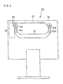
- a liquid crystal television device 50 has an arrangement in which two antenna elements 53a and 53b are built in a handgrip section 52 attached to a cabinet 51.
- the antenna elements 53a and 53b are connected to screws 54a and 54b of the handgrip section 52, in a manner, parallel to each other.
- the arrangement makes it possible to have a diversity antenna structure constructed of the two antenna elements 53a and 53b.
- the portable liquid crystal television device having a simple structure without (i) addition of any extra spaces and (ii) provision of any extra protruding object can be realized, there arises a problem.
- the liquid crystal television device 50 is used in a state where the handgrip section 52 is drawn out from the cabinet (a main body of a display device) 51, sensitivity for receiving an electric wave coming from a front side of a display screen is poor and, moreover, the antennas tend to change the directions in which the antennas are respectively pointing and break easily through contact with an external object.
- the antennas are built in the handgrip. Therefore, the positions in which the antennas are installed are on a rear side of the display section which is electromagnetically shielded. Accordingly, the sensitivity for receiving the electric wave coming from the front side of the display screen is poor.
- the handgrip section 52 in which the antenna elements 53a and 53b are built is positioned on the rear side of the cabinet 51 which is electromagnetically shielded. Therefore, unless the liquid crystal television device is used in the state where the handgrip section 52 is drawn out upward from the cabinet 51, it is difficult to receive an electric wave passing through the cabinet 51 from the front side of the display screen.
- the cabinet 51 there exist many components which act as shields, against the electric wave to be received, such as a liquid crystal panel, wiring substrate, parts of an internal structure, or the like, in addition to the electromagnetic shield. These shields further attenuate the electric wave passing through the entire screen. This causes the sensitivity for receiving the electric wave to be further deteriorated.
- each of the antennas is built outside the main body of the display device, contact with an external object and the like may change the direction in which the antenna is pointed, or break the antenna.
- the antenna elements 53a and 53b are built in the handgrip section 52 attached on the cabinet 51, and by adjusting (i) how much the handgrip section 52 is drawn out and (ii) an angle of the handgrip section 52, the length and the direction of the antenna elements 53a and 53b inside are adjusted. Therefore, when something contacts the handgrip section 52, the directions in which the antenna elements 53a and 53b are pointed change. When the handgrip section 52 is contacted with force, the handgrip section 52 may be broken.
- This breakage of the handgrip section 52 means the breakage of the antennas 53a and 53b.
- a portable liquid crystal television device and the like such devices are used in a variety of places based on the feature of such devices. Accordingly, compared with a fixed television device and the like, a risk of breakage as well as the possibility that something contacts the handgrip section 52 is considered to be high.
- An object of the invention is to provide a wireless communication device having an antenna structure with improved communication sensitivity by being less influenced by the electromagnetic shield.
- the object of the invention is to provide a wireless communication device having an antenna structure that provides good communication sensitivity and, moreover, that does not cause the antenna to change the direction in which the antenna is pointed nor break due to contact with an external object.
- a wireless communication device of the present invention in order to achieve the object mentioned above, includes: an antenna storage section(s), which is formed integrally with a main body of the device and which is not electromagnetically shielded, in a periphery section of a display screen in the main body of the device containing a display section including the display screen; and an antenna(s) being provided inside the antenna storage section(s).
- the antenna is provided inside the antenna storage section, which is integrally formed with the main body section of the device and which is not electromagnetically shielded, in the periphery section of the display screen of the main body of the device containing the display section including the display screen. Therefore, the antenna can receive an electric wave without being influenced by the electromagnetic shield provided in the display section. Accordingly, communication sensitivity for sensing an electric wave including an electric wave coming from a front side of the screen is improved. Moreover, because the antenna storage section is provided in the periphery section of the display screen, the antenna is not influenced by the electromagnetic shield. At the same time, there are few shields, such as the display section, circuit substrate, and other parts, blocking the electric wave. In this respect also, the communication sensitivity is improved.
- the antenna is arranged inside the antenna storage section formed integrally with the main body section of the device, the antenna neither changes a direction in which the antenna is pointed nor breaks upon contact with an external object. Compared with a case in which the antenna is contained in a handgrip as in the conventional art, a storage space can be ensured and the antenna can be arranged so as to prevent directivity of reception.
- Another wireless communication device(s) of the present invention in order to achieve the object mentioned above, includes: an antenna storage section(s), which is formed integrally with a main body of the device and which includes a ventilation section made of plural through-holes, in a periphery section of a display screen in the main body of the device containing a display section including the display screen; and an antenna(s) being provided inside the antenna storage section(s).
- the antenna is provided inside the antenna storage section, which is integrally formed with the main body section of the device and which includes a ventilation section made of plural through-holes, in the periphery section of the display screen of the main body of the device containing the display section including the display screen. Therefore, the antenna can receive an electric wave without being influenced by the electromagnetic shield provided in the display section and the communication sensitivity to an electric wave including a wave coming from a front side of the screen is improved. Moreover, because the antenna storage section is provided in the periphery section of the display screen, the antenna is not influenced by the electromagnetic shield. At the same time, there are few shields, such as the display section, circuit substrate, and other parts, blocking the electric wave. In this respect also, the communication sensitivity is improved.
- the antenna is provided inside the antenna storage section formed integrally with the main body of the device, the antenna does not change the direction in which the antenna is pointed nor breaks upon contact with an external object. Compared with a case in which the antenna is stored in a handgrip as in the conventional art, a storage space can be ensured and the antenna can be arranged so as to prevent the directivity of reception.
- the number of antenna(s) provided in one of the antenna storage section mentioned above may be one or plural.
- the number of antenna storage section(s) also may be plural.
- the antenna storage sections may be provided on both right and left sides of the display screen.
- the antenna storage sections are provided on both left and right sides of the display screen and serve as speaker storage sections, and the antenna(s) and a speaker are stored inside each of the antenna storage sections.
- the speaker storage section for storing the speaker also as the antenna storage section, it is not necessary to add a dedicated space for storing the antenna in the wireless communication device. Moreover, compared with a structure in which the antenna storage section and the speaker storage section are separately provided in the periphery section of the display screen, design of the device can be improved.
- each of the wireless communication devices in addition to the structure mentioned above, two antennas can be provided in the same storage section, and each of the two antennas either in the same storage section of different storage sections, may differ in direction by 90 degrees.
- This structure allows, in a state in which one antenna is provided inside each of the speaker storage sections mentioned above, one of the antennas mentioned above to have directivity in a horizontal plane stronger than directivity in a vertical plane and the other one to have the directivity in the vertical plane stronger than the directivity in the horizontal plane.
- the antenna is either an inverted L antenna or an inverted F antenna.
- FIG.6 is an explanatory diagram schematically illustrating a wireless AV system 1 which is a wireless TV receiver separable from a display.
- the wireless AV system 1 is made of a wireless center unit (hereinafter, called wireless center) 2 as a base device and a main body unit 3 of a television (TV) (hereinafter, called TV main body) as a portable terminal (wireless terminal).
- the wireless center 2 and the TV main body 3 (wireless communication device) as a pair construct a wireless transmission network.
- the TV main body 3 is wireless and includes a built-in battery.
- the TV main body 3 also includes a remote controller 4, and an operation of a video deck and the like by the remote controller is possible.
- the wireless center 2 is connected to AV equipment and the like, such as an antenna for BS (Broadcast Satellite), U/V (UHF/VHF), and the like, a DVD (Digital Versatile Disk) player and a video deck.
- BS Broadcast Satellite
- U/V UHF/VHF
- DVD Digital Versatile Disk
- the TV main body 3 is a thin-model display device, which is separable from the wireless center 2, and mobile or portable by building in a battery.
- the concept of the TV main body 3 is broad and includes various display devices such as a liquid crystal television (hereinafter, called liquid crystal TV), inorganic EL/organic EL displays, and plasma display.
- the TV main body 3 is not limited to being a kind of display systems.
- the TV main body 3 of this embodiment is described as a thin-model display device by taking a liquid crystal TV as an example.
- FIG.1 is a front view of a liquid crystal television device including an antenna structure of a wireless communication device according to the present invention
- FIG.2 is a perspective view of the antenna structure
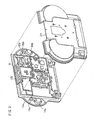
- FIG.3 is an exploded perspective view of this liquid crystal television device.
- this liquid crystal television device 10 includes a main body section 11 in which parts such as a liquid crystal panel section (display section) 13 are contained, and semicircle speaker storage sections (antenna storage sections/ speaker storage sections) 12a and 12b provided on both left and right sides of the main body section 11. These are integrally formed.
- exterior packages of this main body section 11 and the speaker storage sections 12a and 12b are made of a front cabinet 23 and a rear cabinet 24.
- front exterior packages of the main body section 11 and the speaker storage sections 12a and 12b are integrally formed.
- rear exterior packages of the main body section 11 and the speaker storage sections 12a and 12b are integrally formed.
- the front cabinet 23 and rear cabinet 24 have a structure, in which the cabinets 23 and 24 contain parts therebetween, and the cabinets 23 and 24 are fixed by a screw and the like.
- the main body section 11 As mentioned above, in the main body section 11, parts such as the liquid crystal panel section 13 are contained. Moreover, the main body section 11 is provided with an electromagnetic shield so that an electromagnetic wave equal to or more than a certain criterion does not leak outside.
- the speaker storage sections 12a and 12b On an outer surface, sound emission openings 16a and 16b, which are through-holes to the inside, are formed. Inside the speaker storage sections 12a and 12b, speakers 14a and 14b and antennas 15a and 15b are included. The speaker storage sections 12a and 12b are not electromagnetically shielded.
- the heat release opening 17 releases heat from inside the main body section 11.
- All of the sound emission openings 16a and 16b and the heat release opening 17 are ventilation sections that provide ventilation to the inside of the device.
- An area on which the heat releasing opening 17 is formed on the main body section 11 is a periphery section of the liquid panel section 13. The area is outside an edge section of the display screen. Accordingly, the area as well as the speaker storage sections 12a and 12b are not electromagnetically shielded.
- the antennas 15a and 15b are provided in the speaker storage sections 12a and 12b, which are not electromagnetically shielded.
- These speaker storage sections 12a and 12b are provided on external sides of the display screen of the display section 13 and in positions apart from the display section 13 that is electromagnetically shielded. Accordingly, an improved transmitting/receiving sensitivity (communication sensitivity) of the antennas 15a and 15b provided inside the speaker storage sections 12a and 12b can be maintained.
- an external side of the display screen of the display section 13 is a side outside an edge section of the display screen of the display section 13, in any direction illustrated by the arrows in FIG.1.
- the side outside the display screen of the display section is any of (i) an outer area illustrated by arrows a directed to the right from a right edge section of the display screen, the edge section being illustrated by a dotted line L1; (ii) an outer area illustrated by arrows b directed right from an upper edge section of the display screen, the edge section being illustrated by a dotted line L2; (iii) an outer area illustrated by arrows c directed to the left from a left edge section of the display screen, the edge section being illustrated by a dotted line L3; and (iv) an outer area illustrated by arrows a directed downward from a bottom edge section of the display screen, the edge section being illustrated by a dotted line L4.
- the external side of the display screen of the display section is the periphery section of the
- FIG.2 is a perspective view of a structure of the antennas 15a and 15b.
- FIG. 2(a) and 2(b) respectively illustrate an inverted L antenna 15 and an inverted F antenna 26.
- the inverted L antenna 15 is made of an antenna substrate 21 on an orthogon and an antenna element section 22 made of a metal plate whose side surface is shaped in an inverted L.
- the inverted F antenna 26 is made of an antenna substrate 27 on an orthogon and an antenna element section 28 made of a metal plate whose side surface is shaped in an inverted F. Either type of antenna may be used as the antennas 15a and 15b. In this embodiment, the inverted L antenna 15 is used.
- the antennas 15a and 15b are provided so as to have their directions of installation different from each other by 90 degrees.
- the antennas 15a and 15b are respectively provided above the speakers 14a and 14b.
- This installation allows the antenna 15a to have directivity in a horizontal plane stronger than directivity in a vertical plane and the other antenna 15b to have the directivity in the vertical plane stronger than the directivity in the horizontal plane, in a state in which the antennas 15a and 15b are respectively provided in the speaker storage sections 12a and 12b.
- the antennas 15a and 15b may be installed in the same direction.
- the antenna element section 22 is electrically connected to the wireless transmitting/receiving circuit in the main body section 11. These two antennas 15a and 15b serve as a diversity antenna.
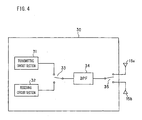
- FIG.4 is a block diagram of a wireless transmitting/receiving circuit 30.
- the wireless transmitting/receiving circuit 30 includes a transmitting circuit section 31 for transmitting a wireless signal, a receiving circuit section 32 for receiving a wireless signal, a band pass filter (BPF) 34 for transmitting/receiving a wireless signal within a frequency range only to/from the antennas 15a and 15b, a changeover switch 33 for switching connections of the transmitting circuit section 31 and the receiving circuit section 32 to the BPF 34 temporally, and a diversity switch for switching connections of the antennas 15a and 15b to the BPF 34 temporally.
- the diversity switch 35 is a time-share switch for connecting the wireless transmitting/receiving circuit section 30, by switching, to the antennas 15a and 15b constituting the diversity antenna temporally, using, for example, a micro computer (not illustrated).
- the BPF34 allows only the wireless signals within the frequency band of the wireless signals used out of the wireless signals inputted into/outputted from the wireless transmitting/receiving circuit section 30 to pass through the BPF 34, thereby causes the antennas 15a and 15b to serve as a diversity antenna.
- the antennas 15a and 15b are stored in the speaker storage sections 12a and 12b that are not covered by an electromagnetic shield, the speaker storage sections 12a and 12b being provided on the outside of the main body section 11 covered by the electromagnetic shield.
- This is advantageous in the respect of transmitting/receiving sensitivity.
- the speaker storage sections 12a and 12b there are few electromagnetic shields such as a liquid crystal panel, substrate, and other parts.
- the above structure is also advantageous in the respect of transmitting/receiving sensitivity.
- the antennas 15a and 15b are contained in the speaker storage sections 12a and 12b, the antennas neither change the direction in which the antennas are pointed nor break upon contact with an external object.
- the antennas 15a and 15b can be arranged so that the directions of the installation of these antennas are different from each other by 90 degrees. Therefore, storing the antennas 15a and 15b in the speaker storage sections 12a and 12b is effective to improve the transmitting/receiving sensitivity in all directions.
- the antennas 15a and 15b are arranged so as to be stored in the speaker storage sections 12a and 12b that is not covered by the electromagnetic shield, the speaker storage sections 12a and 12b being provided to the outside of the main body section 11 covered by the electromagnetic shield.
- the antennas can be provided so as to still have an improved communication sensitivity, when the antennas 15a and 15b are provided in the periphery section of the display screen.
- the periphery section does not need the electromagnetic shield.
- the periphery section is illustrated by the dotted lines L1 through L4 and the arrows a through d.
- antenna storage sections that are not provided with an electromagnetic shield are constructed integrally with the main body section 11, and the antennas 15a and 15b are contained inside the antenna storage sections.
- This can improve the communication sensitivity and can also improve the transmitting/receiving sensitivity in all directions by ensuring enough space for the arrangement.
- the antenna structure does not cause the antenna to change in the direction in which the antennas are pointed nor break due to contact with an external substance.
- the region, on which the heat release opening 17 at the bottom part of the main body section 11 as illustrated in FIG.1 is provided, is in the periphery section of the liquid panel section 13 and the region is outside the edge section of the display screen, the region is not electromagnetically shielded in the same manner as the speaker storage sections 12a and 12b. Therefore, it is possible to provide the antennas 15a and 15b to this part.
- the speaker storage sections 12a and 12b for storing the speakers 14a and 14b are also used as the antenna storage sections. This makes it unnecessary to add a particular space for containing the antennas in the wireless communication device. Moreover, this can improve the design, compared with the arrangement in which the antenna storage sections, which is separate from the speaker storage sections 12a and 12b, are provided in the periphery section of the display screen.
- one antenna is provided in each of the right and left speaker storage sections 12a and 12b.
- a number of antennas provided in each of the speaker storage sections 12a and 12b may be plural, according to the strength of the electric wave to be received and an audio-visual environment of the liquid crystal display device 10.
- a number of antenna storage sections may be single or plural.
- the directions of installation of the two antennas on each of left and right sides may be arranged to be different by 90 degrees. This can better improve usability because flexibility of usage, in which a position of installation and a direction of the installation are not limited, increases in a case where the wireless communication device is used as a portable type.
- the antennas are provided in directions different from each other by 90 degrees so that the usage is not limited by a kind of a wave front of a polarized wave in an electric wave arrived.
- the direction of the installation is not specifically limited to this.
- the direction of the installation may be determined so that the transmitting/receiving sensitivity in all directions becomes high.
- the antennas may be arranged in the same one direction. In this case, a width (depth) of a space in which the antennas are installed can be reduced. Accordingly, the antennas can be utilized in a thin-model device such as a liquid crystal television without detracting from the feature of the device being thin.
- two antennas which are the antennas 15a and 15b, are provided.
- only one antenna may be provided.
- the number of the antenna storage section provided is also one.
- the present invention is preferably applied to portable devices, such as an EL television device, a PDP television device, a CRT television device, mobile phones, and mobile terminal devices, which can be carried around.
- non-electromagnetically shielded sections are provided on external sides of a display screen in a main body section including the display screen displaying a picture image.
- an antenna is provided in each of the non-electromagnetically shielded sections.
- ventilation sections made of plural through-holes are provided on the outer side of a display screen in a main body section including the display screen that displays a picture image.
- an antenna is provided in each of the ventilation sections.
- speaker storage sections are further provided on both left and right sides of the display screen and the antennas are respectively provided inside the speaker storage sections (third wireless communication device).
- one of the antennas is provided in each of the speaker storage sections, and the directions of the installation of the antennas are different from each other by 90 degrees.
- one antenna is stored in each of the speaker storage sections and the directions of installation of the antennas are different from each other by 90 degrees and also, (ii) in a state where one antenna is provided in each of the speaker storage sections, one of the antennas has directivity in a horizontal plane stronger than directivity in a vertical plane, whereas the other antenna has the directivity in the vertical plane stronger than the directivity in the horizontal plane.
- the antenna is either an inverted L antenna or an inverted F antenna at least.
- the antennas are provided on both right and left sides of the main body section by either one of a combination of the same antennas or a combination of different antennas.
- the antennas may be provided in the speaker storage sections so as to provide protrusions from plane surface sections on which the speakers are installed.
- the plane surface sections on which the speakers are provided are surfaces parallel to the opening faces of the speakers in the speaker storage sections 12a and 12b in which the speakers 14a and 14b are installed.
- the plane surface sections are also parallel to the display surface. This arrangement can improve the sensitivity for receiving an electric wave even when a small plate-like plane antenna is installed in a storage section with a limited space.
- the antennas serve as a diversity antenna.
- the antennas are provided in non-electromagnetically shielded sections provided on the external sides of the display screen in the main body section, or, the antennas are provided in the ventilation sections provided on the outside of the display screen in the main body section. Therefore, the antennas are not influenced by an electromagnetic shield. Accordingly, it is possible to better improve the communication sensitivity of the antennas. Moreover, because the antennas are not exposed to the outside of the main body of the display device, the problem of the direction of the antenna changing or the antenna breaking upon contact with an external object and the like can be ameliorated.
- the present invention can be preferably applied to portable devices, such as liquid crystal television devices, EL television devices, PDP television devices, CRT television devices, mobile phones, and mobile terminal devices, which can be carried around.
- portable devices such as liquid crystal television devices, EL television devices, PDP television devices, CRT television devices, mobile phones, and mobile terminal devices, which can be carried around.
Landscapes
- Engineering & Computer Science (AREA)
- Signal Processing (AREA)
- Multimedia (AREA)
- Computer Networks & Wireless Communication (AREA)
- Support Of Aerials (AREA)
- Structure Of Receivers (AREA)
Abstract
Description
- The present invention relates to a wireless communication device. The present invention is favorably applied to portable devices, such as a liquid crystal television device, a PDP (Plasma Display Panel) television device, and a CRT (Cathode Ray Tube) television device, which can be carried around.
- In recent years, portable wireless communication devices, such as a liquid crystal television device and a CRT television device, which can be carried around, have become available. Wireless communication devices for transmitting/receiving a video signal by employing an SS (Spread Spectrum) wireless system based on IEEE802.11 or IEEE802.11B are proposed in these wireless communication devices. Moreover, for such wireless communication devices, not only the wireless system but also a system applicable to a next-generation cellular phone device whose speed of data transfer is increased, PHS (Personal Handy-Phone System) or Blue Tooth, are proposed.
- In such a wireless system, a receiving antenna is necessary. In general, an antenna length of an antenna element for a frequency band of 2.4GHz is around three centimeters, which is equivalent to one quarter of a radio wavelength. Such an antenna is used in an SS wireless system, Blue Tooth wireless system and the like. An antenna length of three centimeters is much shorter than an antenna length of an antenna element for frequency bands of VHF (Very High Frequency) and UHF (Ultra High Frequency) and the three-centimeter antenna is not required to have long shape such as a rod antenna.
- No matter how short an antenna becomes, the antenna element may still protrudes in a noticeable manner in a portable communication device such as a compact liquid crystal television device.
- In Japanese Unexamined Patent Publication 261646/2002 (Tokukai 261646/2002 (published on September 13, 2002), an arrangement in which an antenna element is built inside a handgrip in a portable wireless transmitting/receiving device is disclosed. According to this arrangement, as illustrated in FIG.5, a liquid
crystal television device 50 has an arrangement in which twoantenna elements handgrip section 52 attached to acabinet 51. In this arrangement, theantenna elements screws handgrip section 52, in a manner, parallel to each other. The arrangement makes it possible to have a diversity antenna structure constructed of the twoantenna elements - This realizes a portable liquid crystal television device having a simple structure without (i) addition of any extra spaces and (ii) provision of any extra protruding object.
- Although, in the art disclosed in the Japanese Unexamined Patent Publication mentioned above, the portable liquid crystal television device having a simple structure without (i) addition of any extra spaces and (ii) provision of any extra protruding object can be realized, there arises a problem. Unless the liquid
crystal television device 50 is used in a state where thehandgrip section 52 is drawn out from the cabinet (a main body of a display device) 51, sensitivity for receiving an electric wave coming from a front side of a display screen is poor and, moreover, the antennas tend to change the directions in which the antennas are respectively pointing and break easily through contact with an external object. - Namely, in the art disclosed in the Japanese Unexamined Patent Publication mentioned above, the antennas are built in the handgrip. Therefore, the positions in which the antennas are installed are on a rear side of the display section which is electromagnetically shielded. Accordingly, the sensitivity for receiving the electric wave coming from the front side of the display screen is poor. To be more specific, the
handgrip section 52 in which theantenna elements cabinet 51 which is electromagnetically shielded. Therefore, unless the liquid crystal television device is used in the state where thehandgrip section 52 is drawn out upward from thecabinet 51, it is difficult to receive an electric wave passing through thecabinet 51 from the front side of the display screen. Furthermore, in thecabinet 51, there exist many components which act as shields, against the electric wave to be received, such as a liquid crystal panel, wiring substrate, parts of an internal structure, or the like, in addition to the electromagnetic shield. These shields further attenuate the electric wave passing through the entire screen. This causes the sensitivity for receiving the electric wave to be further deteriorated. - Moreover, because each of the antennas is built outside the main body of the display device, contact with an external object and the like may change the direction in which the antenna is pointed, or break the antenna. In other words, the
antenna elements handgrip section 52 attached on thecabinet 51, and by adjusting (i) how much thehandgrip section 52 is drawn out and (ii) an angle of thehandgrip section 52, the length and the direction of theantenna elements handgrip section 52, the directions in which theantenna elements handgrip section 52 is contacted with force, thehandgrip section 52 may be broken. This breakage of thehandgrip section 52 means the breakage of theantennas handgrip section 52 is considered to be high. - Moreover, in order to eliminate directivity of reception by providing antennas in many directions, a space on which to arrange the antennas is necessary, but it is difficult to allocate such space in the arrangement where the antennas are built in the handgrip section as described in the Japanese Unexamined Patent Publication mentioned above. In order to solve this problem, providing the antennas inside the liquid crystal television device may be considered. However, when provided inside, the antennas are covered by an electromagnetic shield such as unnecessary radiation. Accordingly, this is inconvenient for the purpose of receiving an electromagnetic wave. Furthermore, as mentioned above, there exist many components which act as shields (a liquid panel, wiring substrate, parts of the internal structure and the like) that shield the electric wave to be received inside the liquid crystal television device, and there has been a problem of these shields deteriorating the sensitivity for receiving an electric wave. Therefore, it has been difficult to provide the antennas inside the device.
- The present invention is attained in view of the problems mentioned above. An object of the invention is to provide a wireless communication device having an antenna structure with improved communication sensitivity by being less influenced by the electromagnetic shield. In other words, the object of the invention is to provide a wireless communication device having an antenna structure that provides good communication sensitivity and, moreover, that does not cause the antenna to change the direction in which the antenna is pointed nor break due to contact with an external object.
- A wireless communication device of the present invention, in order to achieve the object mentioned above, includes: an antenna storage section(s), which is formed integrally with a main body of the device and which is not electromagnetically shielded, in a periphery section of a display screen in the main body of the device containing a display section including the display screen; and an antenna(s) being provided inside the antenna storage section(s).
- According to the structure mentioned above, the antenna is provided inside the antenna storage section, which is integrally formed with the main body section of the device and which is not electromagnetically shielded, in the periphery section of the display screen of the main body of the device containing the display section including the display screen. Therefore, the antenna can receive an electric wave without being influenced by the electromagnetic shield provided in the display section. Accordingly, communication sensitivity for sensing an electric wave including an electric wave coming from a front side of the screen is improved. Moreover, because the antenna storage section is provided in the periphery section of the display screen, the antenna is not influenced by the electromagnetic shield. At the same time, there are few shields, such as the display section, circuit substrate, and other parts, blocking the electric wave. In this respect also, the communication sensitivity is improved.
- Furthermore, because the antenna is arranged inside the antenna storage section formed integrally with the main body section of the device, the antenna neither changes a direction in which the antenna is pointed nor breaks upon contact with an external object. Compared with a case in which the antenna is contained in a handgrip as in the conventional art, a storage space can be ensured and the antenna can be arranged so as to prevent directivity of reception.
- This results in providing a wireless communication device including an antenna structure in which the influence of the electromagnetic shield can be suppressed and the communication sensitivity of the antenna is improved. In other words, this is effective for providing a wireless communication device including an antenna structure, which has favorable communication sensitivity and which does not cause the antenna to change the direction in which the antenna is pointed nor break due to contact with an external object.
- Another wireless communication device(s) of the present invention, in order to achieve the object mentioned above, includes: an antenna storage section(s), which is formed integrally with a main body of the device and which includes a ventilation section made of plural through-holes, in a periphery section of a display screen in the main body of the device containing a display section including the display screen; and an antenna(s) being provided inside the antenna storage section(s).
- According to the structure mentioned above, the antenna is provided inside the antenna storage section, which is integrally formed with the main body section of the device and which includes a ventilation section made of plural through-holes, in the periphery section of the display screen of the main body of the device containing the display section including the display screen. Therefore, the antenna can receive an electric wave without being influenced by the electromagnetic shield provided in the display section and the communication sensitivity to an electric wave including a wave coming from a front side of the screen is improved. Moreover, because the antenna storage section is provided in the periphery section of the display screen, the antenna is not influenced by the electromagnetic shield. At the same time, there are few shields, such as the display section, circuit substrate, and other parts, blocking the electric wave. In this respect also, the communication sensitivity is improved.
- Furthermore, because the antenna is provided inside the antenna storage section formed integrally with the main body of the device, the antenna does not change the direction in which the antenna is pointed nor breaks upon contact with an external object. Compared with a case in which the antenna is stored in a handgrip as in the conventional art, a storage space can be ensured and the antenna can be arranged so as to prevent the directivity of reception.
- This results in providing a wireless communication device including an antenna structure in which the influence of the electromagnetic shield can be suppressed and the communication sensitivity of the antenna is improved. In other words, this is effective for providing a wireless communication device including an antenna structure which has improved communication sensitivity and which does not cause the antenna to change the direction in which the antenna is pointed nor break due to contact with an external object.
- Here, the number of antenna(s) provided in one of the antenna storage section mentioned above may be one or plural. Moreover, the number of antenna storage section(s) also may be plural. For example, the antenna storage sections may be provided on both right and left sides of the display screen.
- In each of the wireless communication devices mentioned above, in addition to the structure mentioned above, the antenna storage sections are provided on both left and right sides of the display screen and serve as speaker storage sections, and the antenna(s) and a speaker are stored inside each of the antenna storage sections.
- By using the speaker storage section for storing the speaker also as the antenna storage section, it is not necessary to add a dedicated space for storing the antenna in the wireless communication device. Moreover, compared with a structure in which the antenna storage section and the speaker storage section are separately provided in the periphery section of the display screen, design of the device can be improved.
- Moreover, in each of the wireless communication devices, in addition to the structure mentioned above, two antennas can be provided in the same storage section, and each of the two antennas either in the same storage section of different storage sections, may differ in direction by 90 degrees.
- This structure allows, in a state in which one antenna is provided inside each of the speaker storage sections mentioned above, one of the antennas mentioned above to have directivity in a horizontal plane stronger than directivity in a vertical plane and the other one to have the directivity in the vertical plane stronger than the directivity in the horizontal plane.
- In each of the wireless communication devices, in addition to the structure mentioned above, the antenna is either an inverted L antenna or an inverted F antenna.
- For a fuller understanding of the nature and advantages of the invention, reference should be made to the ensuing detailed description taken in conjunction with the accompanying drawings.
-
- FIG.1 is a front view of a liquid crystal television device having an antenna structure provided in a wireless communication device thereof according to the present invention.
- FIG.2 is a perspective view of the antenna structure. FIG. 2(a) and 2(b) respectively illustrate an inverted L antenna and an inverted F antenna.
- FIG.3 is an exploded perspective view of the liquid crystal television device.
- FIG.4 is a block diagram of a wireless transmitting/ receiving circuit.
- FIG.5 is a rear view of an antenna structure in a conventional liquid crystal television device.
- FIG.6 is an explanatory diagram schematically illustrating a wireless AV (Audio Visual) system in which the liquid crystal television device as illustrated in FIG.1 is provided as a main body unit of a television.
- The present invention is further explained in details below by an exemplary embodiment and a comparative example. However, the present invention is not limited by these at all.
- First, an example of a usage environment, in which a liquid crystal television device (wireless communication device) of an embodiment according to the present invention is provided, is explained with reference to FIG.6.
- FIG.6 is an explanatory diagram schematically illustrating a
wireless AV system 1 which is a wireless TV receiver separable from a display. As illustrated in FIG.6, thewireless AV system 1 is made of a wireless center unit (hereinafter, called wireless center) 2 as a base device and amain body unit 3 of a television (TV) (hereinafter, called TV main body) as a portable terminal (wireless terminal). Thewireless center 2 and the TV main body 3 (wireless communication device) as a pair construct a wireless transmission network. - As illustrated in FIG.6, the TV
main body 3 is wireless and includes a built-in battery. The TVmain body 3 also includes a remote controller 4, and an operation of a video deck and the like by the remote controller is possible. Moreover, thewireless center 2 is connected to AV equipment and the like, such as an antenna for BS (Broadcast Satellite), U/V (UHF/VHF), and the like, a DVD (Digital Versatile Disk) player and a video deck. A video image and/or sound data are/is transmitted from thewireless center 2 to the TVmain body 3 wirelessly. - The TV
main body 3 is a thin-model display device, which is separable from thewireless center 2, and mobile or portable by building in a battery. The concept of the TVmain body 3 is broad and includes various display devices such as a liquid crystal television (hereinafter, called liquid crystal TV), inorganic EL/organic EL displays, and plasma display. The TVmain body 3 is not limited to being a kind of display systems. Hereinafter, the TVmain body 3 of this embodiment is described as a thin-model display device by taking a liquid crystal TV as an example. - FIG.1 is a front view of a liquid crystal television device including an antenna structure of a wireless communication device according to the present invention, and FIG.2 is a perspective view of the antenna structure. FIG.3 is an exploded perspective view of this liquid crystal television device.
- As illustrated in FIG.1, this liquid
crystal television device 10 includes amain body section 11 in which parts such as a liquid crystal panel section (display section) 13 are contained, and semicircle speaker storage sections (antenna storage sections/ speaker storage sections) 12a and 12b provided on both left and right sides of themain body section 11. These are integrally formed. - As illustrated in FIG.3, exterior packages of this
main body section 11 and thespeaker storage sections front cabinet 23 and arear cabinet 24. In thefront cabinet 23, front exterior packages of themain body section 11 and thespeaker storage sections rear cabinet 24, rear exterior packages of themain body section 11 and thespeaker storage sections front cabinet 23 andrear cabinet 24 have a structure, in which thecabinets cabinets - As mentioned above, in the
main body section 11, parts such as the liquidcrystal panel section 13 are contained. Moreover, themain body section 11 is provided with an electromagnetic shield so that an electromagnetic wave equal to or more than a certain criterion does not leak outside. On the other hand, on thespeaker storage sections sound emission openings 16a and 16b, which are through-holes to the inside, are formed. Inside thespeaker storage sections speakers antennas speaker storage sections - Moreover, on a display surface side of the
main body section 11, aheat release opening 17, which is a through-hole to the inside, is formed. The heat release opening 17 releases heat from inside themain body section 11. All of thesound emission openings 16a and 16b and the heat release opening 17 are ventilation sections that provide ventilation to the inside of the device. An area on which theheat releasing opening 17 is formed on themain body section 11 is a periphery section of theliquid panel section 13. The area is outside an edge section of the display screen. Accordingly, the area as well as thespeaker storage sections - In this way, the
antennas speaker storage sections speaker storage sections display section 13 and in positions apart from thedisplay section 13 that is electromagnetically shielded. Accordingly, an improved transmitting/receiving sensitivity (communication sensitivity) of theantennas speaker storage sections - Here, an external side of the display screen of the
display section 13 is a side outside an edge section of the display screen of thedisplay section 13, in any direction illustrated by the arrows in FIG.1. Namely, in the drawing, the side outside the display screen of the display section is any of (i) an outer area illustrated by arrows a directed to the right from a right edge section of the display screen, the edge section being illustrated by a dotted line L1; (ii) an outer area illustrated by arrows b directed right from an upper edge section of the display screen, the edge section being illustrated by a dotted line L2; (iii) an outer area illustrated by arrows c directed to the left from a left edge section of the display screen, the edge section being illustrated by a dotted line L3; and (iv) an outer area illustrated by arrows a directed downward from a bottom edge section of the display screen, the edge section being illustrated by a dotted line L4. In other words, the external side of the display screen of the display section is the periphery section of the display screen. - FIG.2 is a perspective view of a structure of the
antennas inverted L antenna 15 and aninverted F antenna 26. Theinverted L antenna 15 is made of anantenna substrate 21 on an orthogon and anantenna element section 22 made of a metal plate whose side surface is shaped in an inverted L. Theinverted F antenna 26 is made of anantenna substrate 27 on an orthogon and anantenna element section 28 made of a metal plate whose side surface is shaped in an inverted F. Either type of antenna may be used as theantennas inverted L antenna 15 is used. - In the example illustrated by FIG.1 and FIG.3, the
antennas antennas speakers antenna 15a to have directivity in a horizontal plane stronger than directivity in a vertical plane and theother antenna 15b to have the directivity in the vertical plane stronger than the directivity in the horizontal plane, in a state in which theantennas speaker storage sections antennas speaker storage sections antennas - The
antenna element section 22 is electrically connected to the wireless transmitting/receiving circuit in themain body section 11. These twoantennas - FIG.4 is a block diagram of a wireless transmitting/receiving
circuit 30. The wireless transmitting/receivingcircuit 30 includes a transmittingcircuit section 31 for transmitting a wireless signal, a receivingcircuit section 32 for receiving a wireless signal, a band pass filter (BPF) 34 for transmitting/receiving a wireless signal within a frequency range only to/from theantennas changeover switch 33 for switching connections of the transmittingcircuit section 31 and the receivingcircuit section 32 to theBPF 34 temporally, and a diversity switch for switching connections of theantennas BPF 34 temporally. Thediversity switch 35 is a time-share switch for connecting the wireless transmitting/receivingcircuit section 30, by switching, to theantennas - By this structure for connection, the BPF34 allows only the wireless signals within the frequency band of the wireless signals used out of the wireless signals inputted into/outputted from the wireless transmitting/receiving
circuit section 30 to pass through theBPF 34, thereby causes theantennas - As mentioned above, in the liquid
crystal television display 10 of this embodiment, theantennas speaker storage sections speaker storage sections main body section 11 covered by the electromagnetic shield. This is advantageous in the respect of transmitting/receiving sensitivity. Moreover, in thespeaker storage sections antennas speaker storage sections antennas antennas speaker storage sections - In the embodiment of the present invention, the
antennas speaker storage sections speaker storage sections main body section 11 covered by the electromagnetic shield. However, the antennas can be provided so as to still have an improved communication sensitivity, when theantennas - Accordingly, in the periphery section of the display screen, antenna storage sections that are not provided with an electromagnetic shield are constructed integrally with the
main body section 11, and theantennas main body section 11 as illustrated in FIG.1 is provided, is in the periphery section of theliquid panel section 13 and the region is outside the edge section of the display screen, the region is not electromagnetically shielded in the same manner as thespeaker storage sections antennas - In the liquid
crystal television device 10 of the present embodiment, thespeaker storage sections speakers speaker storage sections - In the embodiment of the present invention, one antenna is provided in each of the right and left
speaker storage sections speaker storage sections crystal display device 10. Moreover, a number of antenna storage sections may be single or plural. When two antennas are provided in each of the left and right speaker storage sections, for example, the directions of installation of the two antennas on each of left and right sides may be arranged to be different by 90 degrees. This can better improve usability because flexibility of usage, in which a position of installation and a direction of the installation are not limited, increases in a case where the wireless communication device is used as a portable type. - Moreover, in the embodiment of the present invention, the antennas are provided in directions different from each other by 90 degrees so that the usage is not limited by a kind of a wave front of a polarized wave in an electric wave arrived. However, the direction of the installation is not specifically limited to this. The direction of the installation may be determined so that the transmitting/receiving sensitivity in all directions becomes high. The antennas may be arranged in the same one direction. In this case, a width (depth) of a space in which the antennas are installed can be reduced. Accordingly, the antennas can be utilized in a thin-model device such as a liquid crystal television without detracting from the feature of the device being thin.
- According to this embodiment, two antennas, which are the
antennas - This embodiment is explained by an example in which the antennas are mounted on the liquid crystal television device. However, the device mounting the antennas is not limited to this. For example, the present invention is preferably applied to portable devices, such as an EL television device, a PDP television device, a CRT television device, mobile phones, and mobile terminal devices, which can be carried around.
- The present invention, in other words, can be described as follows. In a wireless communication device (first wireless communication device), non-electromagnetically shielded sections are provided on external sides of a display screen in a main body section including the display screen displaying a picture image. In each of the non-electromagnetically shielded sections, an antenna is provided.
- Moreover, according to the present invention, in the wireless communication device (second wireless communication device), ventilation sections made of plural through-holes are provided on the outer side of a display screen in a main body section including the display screen that displays a picture image. In each of the ventilation sections, an antenna is provided.
- According to the present invention, in these first and second wireless communication devices, speaker storage sections are further provided on both left and right sides of the display screen and the antennas are respectively provided inside the speaker storage sections (third wireless communication device).
- In the third wireless communication device, furthermore, one of the antennas is provided in each of the speaker storage sections, and the directions of the installation of the antennas are different from each other by 90 degrees.
- Further, in the same manner, in the third wireless communication device, (i) one antenna is stored in each of the speaker storage sections and the directions of installation of the antennas are different from each other by 90 degrees and also, (ii) in a state where one antenna is provided in each of the speaker storage sections, one of the antennas has directivity in a horizontal plane stronger than directivity in a vertical plane, whereas the other antenna has the directivity in the vertical plane stronger than the directivity in the horizontal plane.
- In the first to third wireless communication devices, the antenna is either an inverted L antenna or an inverted F antenna at least. The antennas are provided on both right and left sides of the main body section by either one of a combination of the same antennas or a combination of different antennas.
- In the third wireless communication device, the antennas may be provided in the speaker storage sections so as to provide protrusions from plane surface sections on which the speakers are installed. The plane surface sections on which the speakers are provided are surfaces parallel to the opening faces of the speakers in the
speaker storage sections speakers - Furthermore, in the first to third wireless communication devices, the antennas serve as a diversity antenna.
- In this way, according to the present invention, the antennas are provided in non-electromagnetically shielded sections provided on the external sides of the display screen in the main body section, or, the antennas are provided in the ventilation sections provided on the outside of the display screen in the main body section. Therefore, the antennas are not influenced by an electromagnetic shield. Accordingly, it is possible to better improve the communication sensitivity of the antennas. Moreover, because the antennas are not exposed to the outside of the main body of the display device, the problem of the direction of the antenna changing or the antenna breaking upon contact with an external object and the like can be ameliorated.
- The embodiments and concrete examples of implementation discussed in the foregoing detailed explanation serve solely to illustrate the technical details of the present invention, which should not be narrowly interpreted within the limits of such embodiments and concrete examples, but rather may be applied in many variations within the spirit of the present invention, provided such variations do not exceed the scope of the patent claims set forth below.
- The present invention can be preferably applied to portable devices, such as liquid crystal television devices, EL television devices, PDP television devices, CRT television devices, mobile phones, and mobile terminal devices, which can be carried around.
Claims (9)
- A wireless communication device comprising:an antenna storage section(s), which is formed integrally with a main body of the device and which is not electromagnetically shielded, in a periphery section of a display screen in the main body of the device containing a display section including the display screen; andan antenna(s) being provided inside the antenna storage section(s).
- A wireless communication device comprising:an antenna storage section(s), which is formed integrally with a main body of the device and which includes a ventilation section made of plural through-holes, in a periphery section of a display screen in the main body of the device containing a display section including the display screen; andan antenna(s) being provided inside the antenna storage section(s).
- The wireless communication device as set forth in Claims 1 or 2 wherein:one antenna or plural antennas is/are provided in one of the antenna storage section(s).
- The wireless communication device as set forth in Claims 1 or 2, wherein:the antenna storage sections are provided on both left and right sides of the display screen.
- The wireless communication device as set forth in Claims 1 or 2, wherein:the antenna storage sections are provided on both left and right sides of the display screen and serve as speaker storage sections, andthe antenna(s) and a speaker are stored inside each of the antenna storage sections.
- The wireless communication device as set forth in any one of Claims 3 through 5, wherein:directions of installation of two of the antennas provided in the same antenna storage section or different antenna storage sections differ from each other by 90 degrees.
- The wireless communication device as set forth in Claim 6, wherein:in a state in which one antenna is provided inside each of the speaker storage sections, one of the antennas has directivity in a horizontal plane stronger than directivity in a vertical plane and the other one of the antennas has the directivity in the vertical plane stronger than the directivity in the horizontal plane.
- The wireless communication device as set forth in any one of Claims 3 through 7, wherein:plural antennas provided inside the same or different antenna storage section(s) construct a diversity antenna.
- The wireless communication device as set forth in any one of Claims 1 through 8, wherein:the antenna is either an inverted L antenna or an inverted F antenna.
Applications Claiming Priority (3)
| Application Number | Priority Date | Filing Date | Title |
|---|---|---|---|
| JP2003113505 | 2003-04-17 | ||
| JP2004116185A JP3694014B2 (en) | 2003-04-17 | 2004-04-09 | Wireless communication device |
| PCT/JP2004/005420 WO2004093443A1 (en) | 2003-04-17 | 2004-04-15 | Wireless communication device |
Publications (3)
| Publication Number | Publication Date |
|---|---|
| EP1622375A1 true EP1622375A1 (en) | 2006-02-01 |
| EP1622375A4 EP1622375A4 (en) | 2008-01-23 |
| EP1622375B1 EP1622375B1 (en) | 2011-06-15 |
Family
ID=33302233
Family Applications (1)
| Application Number | Title | Priority Date | Filing Date |
|---|---|---|---|
| EP04727738A Expired - Lifetime EP1622375B1 (en) | 2003-04-17 | 2004-04-15 | Wireless communication device |
Country Status (5)
| Country | Link |
|---|---|
| US (1) | US7663554B2 (en) |
| EP (1) | EP1622375B1 (en) |
| JP (1) | JP3694014B2 (en) |
| KR (1) | KR100717228B1 (en) |
| WO (1) | WO2004093443A1 (en) |
Cited By (2)
| Publication number | Priority date | Publication date | Assignee | Title |
|---|---|---|---|---|
| FR2889398A1 (en) * | 2005-07-27 | 2007-02-02 | Archos Sa | PORTABLE GROUND TERMINAL DIGITAL TELEVISION DEVICE COMPRISING A DEVICE FOR RECEIVING A LOW POWER DIGITAL SIGNAL |
| FR2889399A1 (en) * | 2005-07-27 | 2007-02-02 | Archos Sa | PORTABLE GROUND TERMINAL DIGITAL TELEVISION DEVICE COMPRISING A DEVICE FOR RECEIVING A LOW POWER DIGITAL SIGNAL |
Families Citing this family (11)
| Publication number | Priority date | Publication date | Assignee | Title |
|---|---|---|---|---|
| JP2006217272A (en) * | 2005-02-03 | 2006-08-17 | Funai Electric Co Ltd | Setting device of antenna |
| JP4815832B2 (en) * | 2005-03-24 | 2011-11-16 | ソニー株式会社 | Antenna and TV receiver |
| JP5260950B2 (en) * | 2007-12-12 | 2013-08-14 | 三洋電機株式会社 | Television receiver |
| US20100125878A1 (en) * | 2008-11-19 | 2010-05-20 | Sony Corporation | Embedded wireless antenna for network tv |
| KR101559999B1 (en) * | 2008-12-29 | 2015-10-13 | 엘지전자 주식회사 | Display apparatus |
| US20110078749A1 (en) * | 2009-09-29 | 2011-03-31 | Sony Corporation | Embedded wireless antenna for network tv |
| US20110154429A1 (en) * | 2009-12-17 | 2011-06-23 | Winegard Company | Internal television antenna and method for a portable entertainment module |
| US20110187604A1 (en) * | 2010-02-03 | 2011-08-04 | Tse Hsing Chen | Two-way remote controller with hidden antenna |
| WO2021230396A1 (en) * | 2020-05-13 | 2021-11-18 | 엘지전자 주식회사 | Display device |
| JP7661083B2 (en) | 2021-03-26 | 2025-04-14 | Dynabook株式会社 | Electronics |
| KR20240044449A (en) * | 2021-07-28 | 2024-04-04 | 엘지전자 주식회사 | display device |
Family Cites Families (27)
| Publication number | Priority date | Publication date | Assignee | Title |
|---|---|---|---|---|
| JPH0278383A (en) | 1989-07-13 | 1990-03-19 | Casio Comput Co Ltd | pocket tv |
| JPH0756547Y2 (en) | 1990-08-10 | 1995-12-25 | 松下電器産業株式会社 | Portable satellite broadcasting receiver |
| JPH04134907A (en) * | 1990-09-26 | 1992-05-08 | Toyota Central Res & Dev Lab Inc | low profile antenna |
| US5373300A (en) * | 1992-05-21 | 1994-12-13 | International Business Machines Corporation | Mobile data terminal with external antenna |
| JPH0685961A (en) * | 1992-07-14 | 1994-03-25 | Canon Inc | Communication equipment |
| JPH07183844A (en) * | 1993-12-22 | 1995-07-21 | Mitsubishi Electric Corp | Cordless telephone set |
| JPH09188196A (en) * | 1996-01-09 | 1997-07-22 | Tokai Rika Co Ltd | Inner mirror |
| KR19990015425A (en) * | 1997-08-06 | 1999-03-05 | 윤종용 | Registering Speed Dial in Fax Wireless Handheld Device and How to Use It |
| JPH1198046A (en) * | 1997-09-25 | 1999-04-09 | Hitachi Ltd | Information terminal |
| JP2000172376A (en) | 1998-12-08 | 2000-06-23 | Toshiba Corp | Information processing device |
| DK174546B1 (en) | 1998-12-21 | 2003-05-19 | Sony Ericsson Mobile Comm Ab | A communication device |
| US6201501B1 (en) * | 1999-05-28 | 2001-03-13 | Nokia Mobile Phones Limited | Antenna configuration for a mobile station |
| JP3618267B2 (en) | 1999-11-22 | 2005-02-09 | 株式会社東芝 | Antenna device |
| JP2001312339A (en) * | 2000-04-28 | 2001-11-09 | Toshiba Corp | Information processing apparatus, wireless communication card, and antenna connection method for wireless communication card |
| JP2001312336A (en) * | 2000-04-28 | 2001-11-09 | Toshiba Corp | Information processing apparatus with wireless communication function and power saving method for peripheral devices |
| US6339400B1 (en) * | 2000-06-21 | 2002-01-15 | International Business Machines Corporation | Integrated antenna for laptop applications |
| US6687120B2 (en) | 2001-10-17 | 2004-02-03 | Dell Products L.P. | Computer system including speaker-antenna assembly |
| WO2002045418A1 (en) * | 2000-11-30 | 2002-06-06 | Sony Corporation | Monitor device, base device and information terminal device |
| JP2002261646A (en) | 2001-03-02 | 2002-09-13 | Sharp Corp | Wireless transceiver |
| JP2002293131A (en) * | 2001-03-30 | 2002-10-09 | Denso Corp | Vehicle rearview mirror ventilation system |
| US20030003970A1 (en) * | 2001-06-28 | 2003-01-02 | Alan Johnson | Portable communications device |
| JP2003087023A (en) | 2001-09-13 | 2003-03-20 | Toshiba Corp | Portable information equipment with built-in wireless communication antenna |
| JP3888447B2 (en) * | 2002-04-23 | 2007-03-07 | ソニー株式会社 | Wireless communication method and wireless communication apparatus |
| AU2003292710A1 (en) | 2003-01-09 | 2004-08-10 | Sharp Kabushiki Kaisha | Thin display device and method of pulling out display part |
| JP2005136912A (en) * | 2003-10-31 | 2005-05-26 | Toshiba Corp | Information equipment and notebook personal computers |
| CN1918799A (en) * | 2004-02-13 | 2007-02-21 | 夏普株式会社 | Transmitter, radio communication system, program, computer-readable recording medium where program is recorded |
| US20070184883A1 (en) * | 2004-02-13 | 2007-08-09 | Mitsunori Tanaka | Transmitting device, receiving device, communications device, wireless communications system, data transmission method, data reception method, computer program, and computer-readable storage medium containing computer program |
-
2004
- 2004-04-09 JP JP2004116185A patent/JP3694014B2/en not_active Expired - Fee Related
- 2004-04-15 WO PCT/JP2004/005420 patent/WO2004093443A1/en not_active Ceased
- 2004-04-15 US US10/553,343 patent/US7663554B2/en not_active Expired - Fee Related
- 2004-04-15 EP EP04727738A patent/EP1622375B1/en not_active Expired - Lifetime
- 2004-04-15 KR KR1020057019596A patent/KR100717228B1/en not_active Expired - Fee Related
Cited By (3)
| Publication number | Priority date | Publication date | Assignee | Title |
|---|---|---|---|---|
| FR2889398A1 (en) * | 2005-07-27 | 2007-02-02 | Archos Sa | PORTABLE GROUND TERMINAL DIGITAL TELEVISION DEVICE COMPRISING A DEVICE FOR RECEIVING A LOW POWER DIGITAL SIGNAL |
| FR2889399A1 (en) * | 2005-07-27 | 2007-02-02 | Archos Sa | PORTABLE GROUND TERMINAL DIGITAL TELEVISION DEVICE COMPRISING A DEVICE FOR RECEIVING A LOW POWER DIGITAL SIGNAL |
| EP1748651A3 (en) * | 2005-07-27 | 2007-02-21 | Archos | Portable terrestrial digital television device comprising a low power digital signal reception device |
Also Published As
| Publication number | Publication date |
|---|---|
| JP3694014B2 (en) | 2005-09-14 |
| KR100717228B1 (en) | 2007-05-11 |
| US7663554B2 (en) | 2010-02-16 |
| WO2004093443A1 (en) | 2004-10-28 |
| EP1622375B1 (en) | 2011-06-15 |
| EP1622375A4 (en) | 2008-01-23 |
| JP2004336725A (en) | 2004-11-25 |
| US20070096994A1 (en) | 2007-05-03 |
| KR20050121730A (en) | 2005-12-27 |
Similar Documents
| Publication | Publication Date | Title |
|---|---|---|
| EP1286413B1 (en) | Display-antenna integral structure and communication apparatus | |
| CN108512577B (en) | Electronic device with antenna diversity capability | |
| US7663554B2 (en) | Wireless communication device | |
| US12009585B2 (en) | Electronic device equipped with transparent antenna | |
| CN108270088B (en) | Antenna assembly, electronic equipment and antenna switching method | |
| WO2005124923A1 (en) | Mobile telephone | |
| US20220384933A1 (en) | Electronic device having transparent antenna | |
| KR101839425B1 (en) | A portable terminal and method for operating antenna thereof | |
| US12155131B2 (en) | Electronic device having antenna | |
| US6977617B2 (en) | High-frequency receiving unit and high-frequency receiving method | |
| US12015196B2 (en) | Electronic device with antenna | |
| CN108232473A (en) | Antenna module, electronic equipment and antenna switching method | |
| CN212725566U (en) | Module comprising antenna and terminal equipment | |
| CN100376113C (en) | Wireless communication device | |
| WO2021238392A1 (en) | Antenna device and electronic device | |
| JP3980604B2 (en) | Wireless communication device | |
| JP4447363B2 (en) | Wireless communication device | |
| CN109951203B (en) | RF circuits, antenna devices and electronic equipment | |
| KR101240844B1 (en) | Set top box having internal antenna | |
| US7916088B2 (en) | Wireless transceiver | |
| KR200289678Y1 (en) | Apparatus for wireless display | |
| JP2005328112A (en) | Mobile wireless terminal | |
| JP4107649B2 (en) | High frequency wireless communication device | |
| HK1251824B (en) | Antenna assembly, electronic equipment and antenna switching method | |
| HK1186012B (en) | Wireless communications circuitry with a triplexer |
Legal Events
| Date | Code | Title | Description |
|---|---|---|---|
| PUAI | Public reference made under article 153(3) epc to a published international application that has entered the european phase |
Free format text: ORIGINAL CODE: 0009012 |
|
| 17P | Request for examination filed |
Effective date: 20051114 |
|
| AK | Designated contracting states |
Kind code of ref document: A1 Designated state(s): DE ES FR GB |
|
| DAX | Request for extension of the european patent (deleted) | ||
| RBV | Designated contracting states (corrected) |
Designated state(s): DE ES FR GB |
|
| A4 | Supplementary search report drawn up and despatched |
Effective date: 20071228 |
|
| 17Q | First examination report despatched |
Effective date: 20081001 |
|
| GRAC | Information related to communication of intention to grant a patent modified |
Free format text: ORIGINAL CODE: EPIDOSCIGR1 |
|
| GRAP | Despatch of communication of intention to grant a patent |
Free format text: ORIGINAL CODE: EPIDOSNIGR1 |
|
| RIC1 | Information provided on ipc code assigned before grant |
Ipc: H04B 7/10 20060101ALI20101124BHEP Ipc: H04N 5/64 20060101ALI20101124BHEP Ipc: H04N 5/44 20060101AFI20101124BHEP |
|
| RIN1 | Information on inventor provided before grant (corrected) |
Inventor name: AIBA, TATSUSHI Inventor name: KUROYANAGI, HITOSHI |
|
| GRAS | Grant fee paid |
Free format text: ORIGINAL CODE: EPIDOSNIGR3 |
|
| GRAA | (expected) grant |
Free format text: ORIGINAL CODE: 0009210 |
|
| AK | Designated contracting states |
Kind code of ref document: B1 Designated state(s): DE ES FR GB |
|
| REG | Reference to a national code |
Ref country code: GB Ref legal event code: FG4D |
|
| REG | Reference to a national code |
Ref country code: DE Ref legal event code: R096 Ref document number: 602004033075 Country of ref document: DE Effective date: 20110728 |
|
| REG | Reference to a national code |
Ref country code: ES Ref legal event code: FG2A Ref document number: 2365014 Country of ref document: ES Kind code of ref document: T3 Effective date: 20110920 |
|
| PLBE | No opposition filed within time limit |
Free format text: ORIGINAL CODE: 0009261 |
|
| STAA | Information on the status of an ep patent application or granted ep patent |
Free format text: STATUS: NO OPPOSITION FILED WITHIN TIME LIMIT |
|
| 26N | No opposition filed |
Effective date: 20120316 |
|
| REG | Reference to a national code |
Ref country code: DE Ref legal event code: R097 Ref document number: 602004033075 Country of ref document: DE Effective date: 20120316 |
|
| PGFP | Annual fee paid to national office [announced via postgrant information from national office to epo] |
Ref country code: DE Payment date: 20120427 Year of fee payment: 9 |
|
| PGFP | Annual fee paid to national office [announced via postgrant information from national office to epo] |
Ref country code: FR Payment date: 20120416 Year of fee payment: 9 Ref country code: GB Payment date: 20120411 Year of fee payment: 9 |
|
| PGFP | Annual fee paid to national office [announced via postgrant information from national office to epo] |
Ref country code: ES Payment date: 20120403 Year of fee payment: 9 |
|
| GBPC | Gb: european patent ceased through non-payment of renewal fee |
Effective date: 20130415 |
|
| PG25 | Lapsed in a contracting state [announced via postgrant information from national office to epo] |
Ref country code: GB Free format text: LAPSE BECAUSE OF NON-PAYMENT OF DUE FEES Effective date: 20130415 Ref country code: DE Free format text: LAPSE BECAUSE OF NON-PAYMENT OF DUE FEES Effective date: 20131101 |
|
| REG | Reference to a national code |
Ref country code: FR Ref legal event code: ST Effective date: 20131231 |
|
| REG | Reference to a national code |
Ref country code: DE Ref legal event code: R119 Ref document number: 602004033075 Country of ref document: DE Effective date: 20131101 |
|
| PG25 | Lapsed in a contracting state [announced via postgrant information from national office to epo] |
Ref country code: FR Free format text: LAPSE BECAUSE OF NON-PAYMENT OF DUE FEES Effective date: 20130430 |
|
| REG | Reference to a national code |
Ref country code: ES Ref legal event code: FD2A Effective date: 20140613 |
|
| PG25 | Lapsed in a contracting state [announced via postgrant information from national office to epo] |
Ref country code: ES Free format text: LAPSE BECAUSE OF NON-PAYMENT OF DUE FEES Effective date: 20130416 |