EP1621804B1 - Sealing construction - Google Patents
Sealing construction Download PDFInfo
- Publication number
- EP1621804B1 EP1621804B1 EP05076760A EP05076760A EP1621804B1 EP 1621804 B1 EP1621804 B1 EP 1621804B1 EP 05076760 A EP05076760 A EP 05076760A EP 05076760 A EP05076760 A EP 05076760A EP 1621804 B1 EP1621804 B1 EP 1621804B1
- Authority
- EP
- European Patent Office
- Prior art keywords
- sealing
- shaft
- ring
- sealing ring
- axially
- Prior art date
- Legal status (The legal status is an assumption and is not a legal conclusion. Google has not performed a legal analysis and makes no representation as to the accuracy of the status listed.)
- Not-in-force
Links
Images

Classifications
-
- F—MECHANICAL ENGINEERING; LIGHTING; HEATING; WEAPONS; BLASTING
- F16—ENGINEERING ELEMENTS AND UNITS; GENERAL MEASURES FOR PRODUCING AND MAINTAINING EFFECTIVE FUNCTIONING OF MACHINES OR INSTALLATIONS; THERMAL INSULATION IN GENERAL
- F16J—PISTONS; CYLINDERS; SEALINGS
- F16J15/00—Sealings
- F16J15/16—Sealings between relatively-moving surfaces
- F16J15/34—Sealings between relatively-moving surfaces with slip-ring pressed against a more or less radial face on one member
- F16J15/3436—Pressing means
- F16J15/3456—Pressing means without external means for pressing the ring against the face, e.g. slip-ring with a resilient lip
Definitions
- the invention relates to a curd preparation vat comprising a holder with a holder wall and a central shaft which carries cutting and/or stirring members and which, adjacent at least one of the ends, passes through the holder wall, which curd preparation vat is provided with at least one sealing construction for the shaft passing through the holder wall, which sealing construction has at least one receiving space and a sealing ring included therein in operation, surrounding the shaft, wherein the sealing ring has an annular body which is sealingly mounted on the shaft and which is provided with a sealing lip cooperating with a surface of the sealing contruction said surface being stationary relative to the holder wall and extending radially relative to the shaft, and wherein the annular body furthermore has an axially inner surface abutting against first positioning means of the sealing construction which first positioning means are stationary relative to the holder wall.
- curd preparation vats also referred to as curd (preparation) tanks or cheese vats or cheese tanks, are known from practice and are for instance marketed by applicant under the name of Tetra
- United States Patent 4,136,886 discloses a sealing device for a shaft passing through a wall of, for instance, a jam preparation vat or a curd preparation vat.
- the known sealing device comprises an annular chamber formed in a wall part of the holder, enclosing the shaft, which chamber is connected with a supply line for cleaning liquid or with a drain line, depending on the position of a valve.
- an outer sealing ring located in the annular chamber is an outer sealing ring, surrounding the shaft, of the so-called V-type.
- Such a ring has an approximately V-shaped groove in a surface remote from the shaft, thereby forming a lip extending obliquely axially outwards from the shaft, which lip has the free edge resting against a wall of the annular chamber.
- an inner, similar sealing ring is arranged, whose lip has the free edge resting against the surface mentioned.
- flush channels for cleaning fluid are provided between the annular chamber and the interior of the holder.
- the flush channels terminate under the lip of the inner sealing ring, so that it can be pushed away from the wall surface by the pressure of the cleaning liquid to enable a best possible flush of the cleaning liquid.
- the outer sealing ring provides for sealing of the annular chamber in axial direction from the annular chamber to the outside, that is, in a direction away from the interior of the holder.
- the inner sealing ring serves to prevent flow of liquid from the holder into the annular chamber. If leakage occurs nonetheless, the liquid collected in the annular chamber can be drained via the drain line.
- a drawback of the known sealing system is that especially with relatively large holders having a long shaft, for instance curd preparation vats having a content of 20,000 liters and more, still relatively much leakage occurs, which is undesirable.
- the cause of this phenomenon is attributed to both the relatively great radial play of the shaft due to manufacturing tolerances and bending of the shaft, and the relatively great axial play of the shaft owing to expansion differences between the relatively massive shaft and the holder in case of temperature variations.
- the lip of the sealing rings is thereby loaded to such an extent that the sealing action decreases.
- a curd preparation vat of the above-mentioned type is characterized in that the sealing lip of the sealing ring extends both radially and axially obliquely outwards from a both radially and axially outer edge area of the annular body, and that between the sealing lip and the radially inner surface of the annular body abutting against the shaft, there is an axially outer surface of the annular body which cooperates directly with second positioning means, which are stationary relative to the holder wall and which leave the lip clear, for fixing the sealing ring between the first and the second positioning means.
- DE 37 00839 A1 discloses a sealing construction for a holder featuring a sealing ring placed around a shaft.
- This known sealing ring has a sealing lip similar to the sealing lip of the sealing ring of the present invention.
- the known sealing ring is mounted in positioning means which move together with the shaft and thus are not stationary relative to the holder wall.
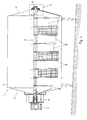
- Fig. 1 schematically shows, largely in vertical longitudinal section, an example of a holder 1 in which the invention can be used.
- the holder is a curd preparation vat, also called cheese vat or curd tank.
- the curd tank comprises a substantially horizontal cylindrical tank 2 with end shields 3 and 4. Extending within the tank in the longitudinal direction is a central shaft 5 which carries curd cutting and stirring members 6 and which is operatively driven for rotation by a driving motor 7.
- Such tanks are typically set up at a slight inclination to simplify emptying of the tank.
- the central shaft is bearing-mounted outside the tank 2 in a bearing construction 8 on the non-driven side, and on the driven side is connected through a coupling construction 9 with the driving motor 7, which at the same time functions as bearing.
- the central shaft 5 has a considerable length, which can be, for instance, in the order of 5 m.
- the central shaft is usually largely solid, that is, designed as a very thick-walled tube.
- the diameter of the shaft can be in the order of, for instance, 10 to 12 cm.
- Such a shaft bends to some extent under its own weight and as a result of the load occurring during operation, which must be taken up adjacent the bearing constructions through a possibility of allowing play.
- the sealing action of the sealing construction should be preserved.
- the holder itself typically having a wall thickness in the order of a few millimeters, for instance 3 mm, expands faster than the central shaft.
- the sealing construction on the side of the outer bearing 8 can shift relative to the central shaft in case of a large tank over a relatively large distance, which can for instance be in the order of 5 mm. This effect should also influence the sealing action to the least possible extent.
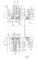
- Fig. 2 shows the portion II of Fig. 1 on a larger scale.
- the central shaft 5 passes from the interior of the tank by way of a reduced journal 10 through a wide opening 11 in the end shield 3 of the tank 2, and through a sealing construction 13, mounted on the end shield 3 via a supporting ring 12, to outside the tank.
- an external bearing construction 8 is mounted, remote from the sealing construction, on the supporting ring 12.
- the bearing construction 8 comprises a bearing house 14 which, in this example, includes a ball bearing 15 which, in this example, receives the slightly further reduced end part 16 of the journal 10.
- the bearing house 14 is connected through a number of radially distributed arms 17, one of which is visible, to a mounting ring 18, which in turn is attached to the supporting ring 12 with bolts 19.
- FIGs. 2 and 3 show the sealing construction at the non-driven end of the central shaft.
- a sealing construction according to the invention can also be used at the other end of the shaft.
- FIG. 2 The example of a sealing construction according to the invention shown in Fig. 2 is shown schematically on a slightly larger scale in Fig. 3.
- the sealing construction in the example shown comprises, viewed in axial direction and with respect to the interior of the tank, an inner sealing ring 20 and a similarly shaped outer sealing ring 21, both fitted on the journal 10.
- the sealing rings are made of suitable elastic material and in this example have an annular body 22 of a substantially rectangular cross section and having an axially outer surface 40, an axially inner surface 41, a radially outer surface 42 and a radially inner surface 43. See also Fig. 4, which schematically shows a cross section of an example of a sealing ring according to the invention on a still slightly larger scale.
- the annular body 22 forms directly a sealing with respect to the journal 10.
- the annular body is provided with a sealing lip 23, which extends obliquely upwards and in mounted condition outwards from the annular body, more specifically, from a both radially and axially outer edge of the annular body.
- the sealing lip 23 extends in line with a diagonal of the annular body, that is, from the transition area between the surfaces 40 and 42 in Fig. 4.
- the sealing lips 23 of sealing rings 20, 21 form a sealing edge 24, which operatively forms a sealing relative to a radial surface of the sealing construction.
- suitable materials for the sealing rings are rubber or rubbery materials, such as for instance food-approved FPM polymers, or EPDM and like materials.
- the sealing construction furthermore comprises a disc-shaped house 25, which is provided with positioning means to fix the sealing rings.
- the disc-shaped house is mounted on the supporting ring 12 with bolts 19a or the like, with interposition of sealing means such as an O-ring 26.
- the disc-shaped house 25 is provided with a central disc-shaped recess, in which a ring 27 is mounted.
- the ring 27 abuts by its surface facing the interior of the tank, with interposition of a first O-ring 28a, against a radial flange 29 of the disc-shaped house 25.
- the ring 27 further abuts by its axially outwardly facing surface, with interposition of a second O-ring 28b, against an annular member 30, which forms a central chamber 31 around the journal 10.
- the central chamber 31 is connected via at least one bore 32 in the annular member 30 with at least one supply line 33 for cleaning liquid.
- the central chamber 31 is furthermore connected via at least one other bore 34 with at least one drain line 35 for leakage fluid and cleaning liquid. It is also possible, however, to use one or more combined supply/drain lines.
- the outer sealing ring 21 is situated in the chamber 31, furthermore.
- the outer wall 36 of the chamber 31 is provided with cams 38 extending axially inwards under the sealing lip 23 of the outer sealing ring 21, which cams 38 abut against the axially outer surface 40 of the annular body 22 of the sealing ring 21.
- cams 38 also an annular shoulder with cross grooves or the like could be used.
- the outer sealing ring 21 furthermore abuts by its axially inner surface 41 against the axially outer surface 50 of the ring 27.
- the ring 27, further, is provided, in its axially outer surface 50 adjacent the sealing ring 21, with radially distributed recesses 51, which form a passage for cleaning liquid.
- the sealing lip 23 of the inner sealing ring 20 then abuts by its sealing edge 24 against the surface 52 of the ring 27.
- the axially inner surface 41 of the inner sealing ring 20 abuts against radially distributed fingers 54 of the disc-shaped house 25.
- the annular bodies of the sealing rings 20 and 21 are directly fixed relative to the end shield 3 of the tank. If the journal 10 and the tank wall move relative to each other in axial direction, the sealing rings remain in the same position relative to the tank wall, and the radially inner surfaces 43 of the sealing rings slide over the journal without the sealing lips 23 thereby being loaded or changing their orientation. The sealing action of the sealing lips 23 is therefore not influenced.
- the fingers 54, the ring 27 and the annular member 30 surround the journal 10 with some clearance "d", thereby allowing a slight radial movement of the journal 10 relative to the sealing construction.
- the sealing edges 24 of the sealing lips slide to some extent over the radial surfaces 37 and 52 of the chamber wall 36 and the ring 27, while the original orientation of the sealing lips is substantially preserved and the sealing action remains guaranteed.
- cleaning liquid is supplied under pressure via the supply line 33 for cleaning liquid and the bore 32 to the chamber 31.
- This cleaning liquid cannot pass the lip 23 of the outer sealing ring 21, but via the recesses 51 in the ring 27 and via the space between the ring 27 and the journal 10 and via the intermediate space between the cams 53, can reach the space 55 under the sealing lip 23 of the inner sealing ring.
- the lip 23 can bend upwards under the influence of the pressure exerted by the cleaning liquid, allowing the cleaning liquid to pass, whereby the space under the lip is cleaned.
- the sealing construction described can be designed with a sealing ring according to the invention in one receiving space and a different type of sealing ring in the other receiving space.
- the sealing construction can be designed with just a single receiving space for a sealing ring. In that case, in the example shown, for instance the outer receiving space situated between the ring 27 and the chamber wall 36, and the sealing ring 21 could be omitted.
- the ring 27 could then be attached by means of bolts or the like to the disc-shaped house 25.
- the sealing would then be provided by the sealing ring 20 situated in the receiving space 31a formed between the axially inner surface of the ring 27 and the fingers 54.
- Such a singular seal could for instance be used in a curd tank for making flat cheese, or in a curd distribution tank for block formers or in a mixing tank for curd and cream.
- a sealing ring according to the invention it would be possible to design the sealing construction with more than two axially consecutive receiving spaces for sealing rings, with a sealing ring according to the invention being used in at least one receiving space.
Landscapes
- Engineering & Computer Science (AREA)
- General Engineering & Computer Science (AREA)
- Mechanical Engineering (AREA)
- Sealing Devices (AREA)
- Sealing With Elastic Sealing Lips (AREA)
- Gasket Seals (AREA)
- Closures For Containers (AREA)
- Sealing Material Composition (AREA)
- Glass Compositions (AREA)
- Materials For Medical Uses (AREA)
- Sealing Battery Cases Or Jackets (AREA)
Abstract
Description
- The invention relates to a curd preparation vat comprising a holder with a holder wall and a central shaft which carries cutting and/or stirring members and which, adjacent at least one of the ends, passes through the holder wall, which curd preparation vat is provided with at least one sealing construction for the shaft passing through the holder wall, which sealing construction has at least one receiving space and a sealing ring included therein in operation, surrounding the shaft, wherein the sealing ring has an annular body which is sealingly mounted on the shaft and which is provided with a sealing lip cooperating with a surface of the sealing contruction said surface being stationary relative to the holder wall and extending radially relative to the shaft, and wherein the annular body furthermore has an axially inner surface abutting against first positioning means of the sealing construction which first positioning means are stationary relative to the holder wall. Such curd preparation vats, also referred to as curd (preparation) tanks or cheese vats or cheese tanks, are known from practice and are for instance marketed by applicant under the name of Tetra Tebel OST.
-
United States Patent 4,136,886 discloses a sealing device for a shaft passing through a wall of, for instance, a jam preparation vat or a curd preparation vat. The known sealing device comprises an annular chamber formed in a wall part of the holder, enclosing the shaft, which chamber is connected with a supply line for cleaning liquid or with a drain line, depending on the position of a valve. Situated in the annular chamber is an outer sealing ring, surrounding the shaft, of the so-called V-type. Such a ring has an approximately V-shaped groove in a surface remote from the shaft, thereby forming a lip extending obliquely axially outwards from the shaft, which lip has the free edge resting against a wall of the annular chamber. Furthermore, on the surface of the wall part comprising the annular chamber that faces the interior of the holder, an inner, similar sealing ring is arranged, whose lip has the free edge resting against the surface mentioned. Between the annular chamber and the interior of the holder, flush channels for cleaning fluid are provided. The flush channels terminate under the lip of the inner sealing ring, so that it can be pushed away from the wall surface by the pressure of the cleaning liquid to enable a best possible flush of the cleaning liquid. During normal use of the holder, the outer sealing ring provides for sealing of the annular chamber in axial direction from the annular chamber to the outside, that is, in a direction away from the interior of the holder. The inner sealing ring serves to prevent flow of liquid from the holder into the annular chamber. If leakage occurs nonetheless, the liquid collected in the annular chamber can be drained via the drain line. - A drawback of the known sealing system is that especially with relatively large holders having a long shaft, for instance curd preparation vats having a content of 20,000 liters and more, still relatively much leakage occurs, which is undesirable. The cause of this phenomenon is attributed to both the relatively great radial play of the shaft due to manufacturing tolerances and bending of the shaft, and the relatively great axial play of the shaft owing to expansion differences between the relatively massive shaft and the holder in case of temperature variations. The lip of the sealing rings is thereby loaded to such an extent that the sealing action decreases.
- The object of the invention is to obviate, at least reduce, the drawbacks outlined. To this end, according to the invention, a curd preparation vat of the above-mentioned type is characterized in that the sealing lip of the sealing ring extends both radially and axially obliquely outwards from a both radially and axially outer edge area of the annular body, and that between the sealing lip and the radially inner surface of the annular body abutting against the shaft, there is an axially outer surface of the annular body which cooperates directly with second positioning means, which are stationary relative to the holder wall and which leave the lip clear, for fixing the sealing ring between the first and the second positioning means.
- Reference is made to
US-A-4 989 504 disclosing a curd preparation vat having a sealing construction for a shaft including a sealing ring provided with two sealing lips. In this known sealing construction however the sealing ring is not mounted on the shaft but on a stationary part of the holder wall. One sealing lip touches the surface of the shaft and the other sealing lip abuts against a radial surface of a flange provided on the shaft. Similar drawbacks as disclosed above in connection with the sealing system ofUS-A-4 136 886 apply. - Further, reference is made to
DE 37 00839 A1 - In the following, the invention will be further described with reference to the accompanying drawing of an exemplary embodiment.
- Fig. 1 schematically shows in vertical longitudinal section an example of a curd preparation tank in which the invention can be used;
- Fig. 2 schematically shows in cross section the portion of Fig. 1 indicated in Fig. 1 by II on a large scale, with a sealing construction according to the invention;
- Fig. 3 schematically shows on a still larger scale the portion III of Fig. 2; and
- Fig. 4 schematically shows in cross section an example of a sealing ring for a sealing construction according to the invention.
- Fig. 1 schematically shows, largely in vertical longitudinal section, an example of a holder 1 in which the invention can be used. In this example, the holder is a curd preparation vat, also called cheese vat or curd tank. The curd tank comprises a substantially horizontal
cylindrical tank 2 withend shields 3 and 4. Extending within the tank in the longitudinal direction is acentral shaft 5 which carries curd cutting and stirringmembers 6 and which is operatively driven for rotation by a drivingmotor 7. Such tanks, as also shown in the drawing, are typically set up at a slight inclination to simplify emptying of the tank. - The central shaft is bearing-mounted outside the
tank 2 in a bearingconstruction 8 on the non-driven side, and on the driven side is connected through acoupling construction 9 with thedriving motor 7, which at the same time functions as bearing. In case of a large tank, which can have a content of, for instance, 20,000 liters or more, thecentral shaft 5 has a considerable length, which can be, for instance, in the order of 5 m. The central shaft is usually largely solid, that is, designed as a very thick-walled tube. The diameter of the shaft can be in the order of, for instance, 10 to 12 cm. Such a shaft bends to some extent under its own weight and as a result of the load occurring during operation, which must be taken up adjacent the bearing constructions through a possibility of allowing play. At the same time, however, the sealing action of the sealing construction should be preserved. - Furthermore, upon a temperature increase, the holder itself, typically having a wall thickness in the order of a few millimeters, for
instance 3 mm, expands faster than the central shaft. As a result, for instance during cleaning procedures, involving flushing with heated cleaning liquid, the sealing construction on the side of theouter bearing 8 can shift relative to the central shaft in case of a large tank over a relatively large distance, which can for instance be in the order of 5 mm. This effect should also influence the sealing action to the least possible extent. - Fig. 2 shows the portion II of Fig. 1 on a larger scale. The
central shaft 5 passes from the interior of the tank by way of a reducedjournal 10 through awide opening 11 in theend shield 3 of thetank 2, and through a sealingconstruction 13, mounted on theend shield 3 via a supportingring 12, to outside the tank. Furthermore, beyond the sealingconstruction 13, anexternal bearing construction 8 is mounted, remote from the sealing construction, on the supportingring 12. Thebearing construction 8 comprises abearing house 14 which, in this example, includes a ball bearing 15 which, in this example, receives the slightly further reducedend part 16 of thejournal 10. Thebearing house 14 is connected through a number of radially distributedarms 17, one of which is visible, to amounting ring 18, which in turn is attached to the supportingring 12 withbolts 19. - It is noted that Figs. 2 and 3 show the sealing construction at the non-driven end of the central shaft. However, a sealing construction according to the invention can also be used at the other end of the shaft.
- The example of a sealing construction according to the invention shown in Fig. 2 is shown schematically on a slightly larger scale in Fig. 3. In Figs. 2 and 3 it can be seen that the sealing construction in the example shown comprises, viewed in axial direction and with respect to the interior of the tank, an
inner sealing ring 20 and a similarly shapedouter sealing ring 21, both fitted on thejournal 10. - The sealing rings are made of suitable elastic material and in this example have an
annular body 22 of a substantially rectangular cross section and having an axiallyouter surface 40, an axiallyinner surface 41, a radiallyouter surface 42 and a radiallyinner surface 43. See also Fig. 4, which schematically shows a cross section of an example of a sealing ring according to the invention on a still slightly larger scale. Theannular body 22 forms directly a sealing with respect to thejournal 10. Furthermore, the annular body is provided with asealing lip 23, which extends obliquely upwards and in mounted condition outwards from the annular body, more specifically, from a both radially and axially outer edge of the annular body. In the example shown, thesealing lip 23 extends in line with a diagonal of the annular body, that is, from the transition area between thesurfaces lips 23 ofsealing rings edge 24, which operatively forms a sealing relative to a radial surface of the sealing construction. - Examples of suitable materials for the sealing rings are rubber or rubbery materials, such as for instance food-approved FPM polymers, or EPDM and like materials.
- The sealing construction furthermore comprises a disc-
shaped house 25, which is provided with positioning means to fix the sealing rings. The disc-shaped house is mounted on the supportingring 12 withbolts 19a or the like, with interposition of sealing means such as an O-ring 26. - In this example, the disc-
shaped house 25 is provided with a central disc-shaped recess, in which aring 27 is mounted. Thering 27 abuts by its surface facing the interior of the tank, with interposition of a first O-ring 28a, against aradial flange 29 of the disc-shaped house 25. Thering 27 further abuts by its axially outwardly facing surface, with interposition of a second O-ring 28b, against anannular member 30, which forms acentral chamber 31 around thejournal 10. Thecentral chamber 31 is connected via at least onebore 32 in theannular member 30 with at least onesupply line 33 for cleaning liquid. Thecentral chamber 31 is furthermore connected via at least oneother bore 34 with at least onedrain line 35 for leakage fluid and cleaning liquid. It is also possible, however, to use one or more combined supply/drain lines. - In the
chamber 31, furthermore, theouter sealing ring 21 is situated. Thelip 23 of theouter sealing ring 21, extending obliquely outwards from the radially and axially outer edge of the annular body, has its sealingedge 24 abutting against a radialinner surface 37 of anouter wall 36 of thechamber 31. - Furthermore, adjacent the
journal 10, theouter wall 36 of thechamber 31 is provided withcams 38 extending axially inwards under the sealinglip 23 of theouter sealing ring 21, which cams 38 abut against the axiallyouter surface 40 of theannular body 22 of the sealingring 21. Instead of thecams 38, also an annular shoulder with cross grooves or the like could be used. - The
outer sealing ring 21 furthermore abuts by its axiallyinner surface 41 against the axiallyouter surface 50 of thering 27. Thering 27, further, is provided, in its axiallyouter surface 50 adjacent the sealingring 21, with radially distributed recesses 51, which form a passage for cleaning liquid. Thering 27, similarly to thechamber wall 36, is provided, on the axially inner surface 52, that is, the surface facing the interior of the tank, withcams 53 or the like which, under the sealinglip 23 of the inner sealing ring, abut against the axiallyouter surface 40 of theinner sealing ring 20. The sealinglip 23 of theinner sealing ring 20 then abuts by its sealingedge 24 against the surface 52 of thering 27. - The axially
inner surface 41 of theinner sealing ring 20 abuts against radially distributedfingers 54 of the disc-shapedhouse 25. - As a result of the construction described, the annular bodies of the sealing rings 20 and 21 are directly fixed relative to the
end shield 3 of the tank. If thejournal 10 and the tank wall move relative to each other in axial direction, the sealing rings remain in the same position relative to the tank wall, and the radiallyinner surfaces 43 of the sealing rings slide over the journal without the sealinglips 23 thereby being loaded or changing their orientation. The sealing action of the sealinglips 23 is therefore not influenced. - The
fingers 54, thering 27 and theannular member 30 surround thejournal 10 with some clearance "d", thereby allowing a slight radial movement of thejournal 10 relative to the sealing construction. Upon such a movement, the sealing edges 24 of the sealing lips slide to some extent over the radial surfaces 37 and 52 of thechamber wall 36 and thering 27, while the original orientation of the sealing lips is substantially preserved and the sealing action remains guaranteed. - If in the
chamber 31 and/or in the interior of the tank an increased liquid pressure occurs, the sealinglips 23 of the sealing rings are pushed more firmly against thesurfaces 37 and 52, respectively, so that the sealing action can increase further. - During a cleaning cycle, with the
drain line 35 closed, cleaning liquid is supplied under pressure via thesupply line 33 for cleaning liquid and thebore 32 to thechamber 31. This cleaning liquid cannot pass thelip 23 of theouter sealing ring 21, but via therecesses 51 in thering 27 and via the space between thering 27 and thejournal 10 and via the intermediate space between thecams 53, can reach thespace 55 under the sealinglip 23 of the inner sealing ring. Thelip 23 can bend upwards under the influence of the pressure exerted by the cleaning liquid, allowing the cleaning liquid to pass, whereby the space under the lip is cleaned. - It is noted that after the foregoing, various constructional modifications will readily occur to those skilled in the art. Thus, if desired, the sealing construction described can be designed with a sealing ring according to the invention in one receiving space and a different type of sealing ring in the other receiving space. Also, if desired, the sealing construction can be designed with just a single receiving space for a sealing ring. In that case, in the example shown, for instance the outer receiving space situated between the
ring 27 and thechamber wall 36, and the sealingring 21 could be omitted. Thering 27 could then be attached by means of bolts or the like to the disc-shapedhouse 25. The sealing would then be provided by the sealingring 20 situated in the receivingspace 31a formed between the axially inner surface of thering 27 and thefingers 54. Such a singular seal could for instance be used in a curd tank for making flat cheese, or in a curd distribution tank for block formers or in a mixing tank for curd and cream. Furthermore, if desired, it would be possible to design the sealing construction with more than two axially consecutive receiving spaces for sealing rings, with a sealing ring according to the invention being used in at least one receiving space. - These and similar modifications are understood to fall within the framework of the invention, which is defined by the scope of the appended claims.
Claims (12)
- A curd preparation vat comprising a holder (1) with a holder wall (2,3,4) and a central shaft (5,10) which carries cutting and/or stirring members (6) and which, adjacent at least one of the ends, passes through the holder wall (2,3,4), which curd preparation vat is provided with at least one sealing construction (13) for the shaft (5,10) passing through the holder wall (2,3,4), which sealing construction (13) has at least one receiving space (31) and a sealing ring (20;21) included therein in operation, wherein the sealing ring (20,21) has an annular body (22) which is sealingly mounted on the shaft (5,10) and which is provided with a sealing lip (23) cooperating with a surface (37,52) of the sealing construction (13), said surface being stationary relative to the holder wall (2,3,4) and extending radially relative to the shaft (5,10), and wherein the annular body (22) furthermore has an axially inner surface (41) abutting against first positioning means (27;54) of the sealing construction (13), which first positioning means are stationary relative to the holder wall, characterized in that the sealing lip (23) of the sealing ring (20;21) extends both radially and axially obliquely outwards from a both radially and axially outer edge area of the annular body (22), and in that between the sealing lip (23) and the radially inner surface (43) of the annular body (22) that abuts against the shaft (5,10), an axially outer surface (40) of the annular body (22) is situated, which cooperates directly with second positioning means (38;53), which are stationary relative to the holder wall and which leave the lip (23) clear, for fixing the sealing ring (20,21) between the first (27;54) and the second (38;53) positioning means.
- A curd preparation vat according to claim 1, characterized in that the second positioning means (38;53) comprise cams, which, adjacent the shaft, extend from the surface (37;52) extending radially relative to the shaft (5,10) to the axially outer surface (40) of the annular body (22).
- A curd preparation vat according to claim 1 or 2, characterized in that the first positioning means (27;54) comprise a number of radial arms (54), which extend from positions spaced from the shaft (5,10) in radial direction to a point near the shaft.
- A curd preparation vat according to claim 1, 2 or 3, wherein the sealing construction (13) has an axially inner (31a) and outer (31) receiving space, and, operatively included therein, a respective inner (20) and outer (21) sealing ring surrounding the shaft (5,10), and wherein at least the inner sealing ring (20) has a sealing lip (23) according to claim 1, characterized by a disc-shaped house (25) which is operatively attached to the holder wall (2,3,4) and is provided with a central passage for the shaft (5,10), and with a central chamber, in which a ring (27) surrounding the shaft (5,10) is placed, having an axially outer surface (50) and an axially inner surface (52), wherein the axially outer surface (50) of the ring (27) abuts against the axially inner surface (41) of the outer sealing ring (21), and wherein the second positioning means comprise radially distributed cams (53) provided on the axially inner surface (52) of the ring (27), which cams (53) abut against the axially outer surface (40) of the inner sealing ring (20), while the sealing lip (23) of the inner sealing ring (20), at a position situated radially beyond the cams (53), abuts against the axially inner surface (52) of the ring (27).
- A curd preparation vat according to claim 4, characterized in that the first positioning means comprise radially distributed fingers (54) arranged on the disc-shaped house (25), situated axially inwards with respect to the ring (27), extending towards the shaft (5,10), which fingers(54) abut against the axially inner surface (41) of the inner sealing ring (20) and together with the cams (53) of the ring (27) fix the inner sealing ring (20).
- A curd preparation vat according to claim 4 or 5, wherein the outer sealing ring (21) has a sealing lip (23) according to claim 1, characterized in that the sealing lip (23) of the outer sealing ring (21), spaced from the shaft (5,10), rests against the inner surface (37) of a radial outer wall (36), closing the central chamber (31), of an annular member (30) enclosing the shaft (5,10), which inner surface (37), furthermore, is provided, adjacent the shaft (5,10), with axially inwardly extending positioning means (38), which form part of the second positioning means for the outer sealing ring (21) and which, between the lip (23) and the shaft (5,10), abut against the axially outer surface (40) of the annular body (22) of the outer sealing ring (21), and which, together with the axially outer surface (50) of the ring (27) placed in the central chamber, fix the outer sealing ring (21).
- A curd preparation vat according to claim 6, characterized in that the inwardly extending positioning means provided on the inner surface (37) of the radial outer wall (36) comprise cams (38).
- A curd preparation vat according to any one of claims 4 to 7, characterized in that the ring (27) placed in the central chamber surrounds the shaft (5,10) with some clearance (d) and that the ring (27) is provided with recesses (51) in the axially outer surface (50) adjacent the outer sealing ring (21), which recesses (51), together with the clearance (d) between the ring (27) and the shaft (5,10), form a liquid passage which connects the central chamber (31) with the space (55) between the shaft (5,10) and the sealing lip (23) of the inner sealing ring (20).
- A curd preparation vat according to any one of claims 4 to 8, characterized in that the central chamber (31) is connected with at least one o drain line (35) and at least one supply line (33) for cleaning liquid.
- A curd preparation vat according to any one of claims 4 to 9, characterized in that on the outside of the disc-shaped house (25) a number of arms (17) are attached which carry a bearing construction (8) for the central shaft (5,10), situated at an axial distance from the sealing construction (13).
- A curd preparation vat according to any one of the preceding claims, characterized in that the curd preparation vat is an elongate vat which is arranged to be set up in horizontal position.
- A curd preparation vat according to any one of the preceding claims, provided with a shaft (5,10) having a great length in the order of about 3 m or more.
Priority Applications (1)
| Application Number | Priority Date | Filing Date | Title |
|---|---|---|---|
| PL05076760T PL1621804T3 (en) | 2004-07-30 | 2005-07-29 | Sealing construction |
Applications Claiming Priority (1)
| Application Number | Priority Date | Filing Date | Title |
|---|---|---|---|
| NL1026756A NL1026756C2 (en) | 2004-07-30 | 2004-07-30 | Sealing construction. |
Publications (2)
| Publication Number | Publication Date |
|---|---|
| EP1621804A1 EP1621804A1 (en) | 2006-02-01 |
| EP1621804B1 true EP1621804B1 (en) | 2007-09-26 |
Family
ID=34974241
Family Applications (1)
| Application Number | Title | Priority Date | Filing Date |
|---|---|---|---|
| EP05076760A Not-in-force EP1621804B1 (en) | 2004-07-30 | 2005-07-29 | Sealing construction |
Country Status (10)
| Country | Link |
|---|---|
| US (1) | US7544917B2 (en) |
| EP (1) | EP1621804B1 (en) |
| AT (1) | ATE374330T1 (en) |
| AU (1) | AU2005203362B2 (en) |
| CA (1) | CA2514008C (en) |
| DE (1) | DE602005002596T2 (en) |
| DK (1) | DK1621804T3 (en) |
| NL (1) | NL1026756C2 (en) |
| NZ (1) | NZ541574A (en) |
| PL (1) | PL1621804T3 (en) |
Families Citing this family (5)
| Publication number | Priority date | Publication date | Assignee | Title |
|---|---|---|---|---|
| WO2007132723A1 (en) * | 2006-05-13 | 2007-11-22 | Yasunori Onozuka | Object to be subjected to spraying, having portion with specialized shape |
| US20110254231A1 (en) * | 2010-04-19 | 2011-10-20 | Isenberg Timothy J | Clean-In-Place Seal Assembly |
| US8944277B2 (en) | 2010-04-19 | 2015-02-03 | Cheese & Whey Systems, Inc. | Food processing vat with a clean-in-place vent |
| US9188163B2 (en) | 2010-04-19 | 2015-11-17 | Custom Fabricating & Repair, Inc. | Clean-in place shaft bushing |
| US8979356B2 (en) | 2012-12-18 | 2015-03-17 | Feldmeier Equipment, Inc. | Dual agitator mixer with sanitary tank |
Family Cites Families (11)
| Publication number | Priority date | Publication date | Assignee | Title |
|---|---|---|---|---|
| US3038733A (en) * | 1958-10-10 | 1962-06-12 | Chicago Rawhide Mfg Co | Gap seal |
| GB1025999A (en) * | 1964-03-09 | 1966-04-14 | Stensholms Fabriks Ab | Improvements in shaft oil seals |
| SE326082B (en) * | 1969-01-29 | 1970-07-13 | B Eriksson | |
| US3934311A (en) * | 1973-07-13 | 1976-01-27 | Thompson John W | Oyster breaker operated by electric motor having bearing seal device |
| US4071255A (en) * | 1976-10-12 | 1978-01-31 | Morgan Construction Company | Flexible seal element with reinforced drain labyrinth |
| SE404414B (en) | 1977-02-25 | 1978-10-02 | Alfa Laval Ab | DEVICE FOR DISHING A FIRST SEAL RING AND A SPACE NEARLY NEXT THE SEAL RING |
| DE3700839A1 (en) * | 1987-01-14 | 1988-07-28 | Heinz Konrad Prof Dr I Mueller | Shaft seal |
| JPH0722532Y2 (en) * | 1988-06-14 | 1995-05-24 | エヌオーケー株式会社 | Sealing device |
| US4989504A (en) * | 1988-11-09 | 1991-02-05 | Sherping Systems, Inc. | Food processing vat |
| US4973063A (en) * | 1989-07-14 | 1990-11-27 | Itt Corporation | Tandem mounted face seals |
| NL1015016C2 (en) * | 2000-04-25 | 2001-10-26 | Tetra Laval Holdings & Finance | Device for cutting and stirring curd. |
-
2004
- 2004-07-30 NL NL1026756A patent/NL1026756C2/en not_active IP Right Cessation
-
2005
- 2005-07-28 CA CA2514008A patent/CA2514008C/en not_active Expired - Fee Related
- 2005-07-29 PL PL05076760T patent/PL1621804T3/en unknown
- 2005-07-29 US US11/192,931 patent/US7544917B2/en not_active Expired - Fee Related
- 2005-07-29 EP EP05076760A patent/EP1621804B1/en not_active Not-in-force
- 2005-07-29 AU AU2005203362A patent/AU2005203362B2/en not_active Ceased
- 2005-07-29 NZ NZ541574A patent/NZ541574A/en not_active IP Right Cessation
- 2005-07-29 DE DE602005002596T patent/DE602005002596T2/en active Active
- 2005-07-29 DK DK05076760T patent/DK1621804T3/en active
- 2005-07-29 AT AT05076760T patent/ATE374330T1/en not_active IP Right Cessation
Also Published As
| Publication number | Publication date |
|---|---|
| NZ541574A (en) | 2006-05-26 |
| US7544917B2 (en) | 2009-06-09 |
| CA2514008C (en) | 2010-09-07 |
| NL1026756C2 (en) | 2006-01-31 |
| DE602005002596D1 (en) | 2007-11-08 |
| CA2514008A1 (en) | 2006-01-30 |
| PL1621804T3 (en) | 2008-04-30 |
| ATE374330T1 (en) | 2007-10-15 |
| DE602005002596T2 (en) | 2008-06-26 |
| DK1621804T3 (en) | 2008-02-04 |
| US20060021518A1 (en) | 2006-02-02 |
| EP1621804A1 (en) | 2006-02-01 |
| AU2005203362B2 (en) | 2008-02-28 |
| AU2005203362A1 (en) | 2006-02-16 |
Similar Documents
| Publication | Publication Date | Title |
|---|---|---|
| EP1621804B1 (en) | Sealing construction | |
| GB2235737A (en) | Mechanical seal unit | |
| US20150375981A1 (en) | Rotary distributor for distributing free-flowing media | |
| SE515100C2 (en) | Device for sealing a gap | |
| US4473171A (en) | Nozzle construction for jacketed pressure vessels | |
| EP4075002B1 (en) | Support assembly for food applications having an improved rear sealing device | |
| EP4075003B1 (en) | Support assembly for food applications having an improved inner seal | |
| US7950411B2 (en) | Pipe branching arrangement | |
| US20180163784A1 (en) | Needle bearing unit for mounting a valve shaft or actuator shaft and gas control valve arrangement | |
| FI95168C (en) | Shaft seal | |
| US6142476A (en) | Mechanical seal | |
| EP3916258B1 (en) | Cover for a bearing housing and support assembly for an associated rotating shaft | |
| CA2726068C (en) | Piping system for process plants in the food and beverage industry | |
| EP1486706A1 (en) | Self-Cleaning valve | |
| US4529212A (en) | Heat exchanger seal | |
| EP3581263A1 (en) | Agitator arrangement | |
| EP4299932A1 (en) | Support assembly for food applications | |
| US20220161161A1 (en) | Screen having variable circumference for a thermostatic valve | |
| US20070182105A1 (en) | Seal configuration | |
| KR200165917Y1 (en) | 4way 4Port valve | |
| EP3837456B1 (en) | Shut-off device for sealing a shaft of a rotary machine and rotary machine | |
| KR100572220B1 (en) | A sludge preventing type water valve and manufacturing method of valve seat | |
| KR100528501B1 (en) | Sluice valve with air venting function | |
| CN114251371A (en) | High-emission hub unit |
Legal Events
| Date | Code | Title | Description |
|---|---|---|---|
| PUAI | Public reference made under article 153(3) epc to a published international application that has entered the european phase |
Free format text: ORIGINAL CODE: 0009012 |
|
| AK | Designated contracting states |
Kind code of ref document: A1 Designated state(s): AT BE BG CH CY CZ DE DK EE ES FI FR GB GR HU IE IS IT LI LT LU LV MC NL PL PT RO SE SI SK TR |
|
| AX | Request for extension of the european patent |
Extension state: AL BA HR MK YU |
|
| 17P | Request for examination filed |
Effective date: 20060502 |
|
| 17Q | First examination report despatched |
Effective date: 20060628 |
|
| AKX | Designation fees paid |
Designated state(s): AT BE BG CH CY CZ DE DK EE ES FI FR GB GR HU IE IS IT LI LT LU LV MC NL PL PT RO SE SI SK TR |
|
| GRAP | Despatch of communication of intention to grant a patent |
Free format text: ORIGINAL CODE: EPIDOSNIGR1 |
|
| GRAS | Grant fee paid |
Free format text: ORIGINAL CODE: EPIDOSNIGR3 |
|
| GRAA | (expected) grant |
Free format text: ORIGINAL CODE: 0009210 |
|
| AK | Designated contracting states |
Kind code of ref document: B1 Designated state(s): AT BE BG CH CY CZ DE DK EE ES FI FR GB GR HU IE IS IT LI LT LU LV MC NL PL PT RO SE SI SK TR |
|
| REG | Reference to a national code |
Ref country code: GB Ref legal event code: FG4D |
|
| REG | Reference to a national code |
Ref country code: CH Ref legal event code: EP |
|
| REF | Corresponds to: |
Ref document number: 602005002596 Country of ref document: DE Date of ref document: 20071108 Kind code of ref document: P |
|
| REG | Reference to a national code |
Ref country code: IE Ref legal event code: FG4D |
|
| PG25 | Lapsed in a contracting state [announced via postgrant information from national office to epo] |
Ref country code: LT Free format text: LAPSE BECAUSE OF FAILURE TO SUBMIT A TRANSLATION OF THE DESCRIPTION OR TO PAY THE FEE WITHIN THE PRESCRIBED TIME-LIMIT Effective date: 20070926 Ref country code: FI Free format text: LAPSE BECAUSE OF FAILURE TO SUBMIT A TRANSLATION OF THE DESCRIPTION OR TO PAY THE FEE WITHIN THE PRESCRIBED TIME-LIMIT Effective date: 20070926 |
|
| REG | Reference to a national code |
Ref country code: DK Ref legal event code: T3 |
|
| PG25 | Lapsed in a contracting state [announced via postgrant information from national office to epo] |
Ref country code: AT Free format text: LAPSE BECAUSE OF FAILURE TO SUBMIT A TRANSLATION OF THE DESCRIPTION OR TO PAY THE FEE WITHIN THE PRESCRIBED TIME-LIMIT Effective date: 20070926 |
|
| PG25 | Lapsed in a contracting state [announced via postgrant information from national office to epo] |
Ref country code: BE Free format text: LAPSE BECAUSE OF FAILURE TO SUBMIT A TRANSLATION OF THE DESCRIPTION OR TO PAY THE FEE WITHIN THE PRESCRIBED TIME-LIMIT Effective date: 20070926 Ref country code: LV Free format text: LAPSE BECAUSE OF FAILURE TO SUBMIT A TRANSLATION OF THE DESCRIPTION OR TO PAY THE FEE WITHIN THE PRESCRIBED TIME-LIMIT Effective date: 20070926 |
|
| REG | Reference to a national code |
Ref country code: CH Ref legal event code: PL |
|
| PG25 | Lapsed in a contracting state [announced via postgrant information from national office to epo] |
Ref country code: GR Free format text: LAPSE BECAUSE OF FAILURE TO SUBMIT A TRANSLATION OF THE DESCRIPTION OR TO PAY THE FEE WITHIN THE PRESCRIBED TIME-LIMIT Effective date: 20071227 Ref country code: ES Free format text: LAPSE BECAUSE OF FAILURE TO SUBMIT A TRANSLATION OF THE DESCRIPTION OR TO PAY THE FEE WITHIN THE PRESCRIBED TIME-LIMIT Effective date: 20080106 Ref country code: CH Free format text: LAPSE BECAUSE OF FAILURE TO SUBMIT A TRANSLATION OF THE DESCRIPTION OR TO PAY THE FEE WITHIN THE PRESCRIBED TIME-LIMIT Effective date: 20070926 Ref country code: LI Free format text: LAPSE BECAUSE OF FAILURE TO SUBMIT A TRANSLATION OF THE DESCRIPTION OR TO PAY THE FEE WITHIN THE PRESCRIBED TIME-LIMIT Effective date: 20070926 |
|
| REG | Reference to a national code |
Ref country code: PL Ref legal event code: T3 |
|
| PG25 | Lapsed in a contracting state [announced via postgrant information from national office to epo] |
Ref country code: PT Free format text: LAPSE BECAUSE OF FAILURE TO SUBMIT A TRANSLATION OF THE DESCRIPTION OR TO PAY THE FEE WITHIN THE PRESCRIBED TIME-LIMIT Effective date: 20080226 Ref country code: SK Free format text: LAPSE BECAUSE OF FAILURE TO SUBMIT A TRANSLATION OF THE DESCRIPTION OR TO PAY THE FEE WITHIN THE PRESCRIBED TIME-LIMIT Effective date: 20070926 Ref country code: IS Free format text: LAPSE BECAUSE OF FAILURE TO SUBMIT A TRANSLATION OF THE DESCRIPTION OR TO PAY THE FEE WITHIN THE PRESCRIBED TIME-LIMIT Effective date: 20080126 Ref country code: CZ Free format text: LAPSE BECAUSE OF FAILURE TO SUBMIT A TRANSLATION OF THE DESCRIPTION OR TO PAY THE FEE WITHIN THE PRESCRIBED TIME-LIMIT Effective date: 20070926 |
|
| PG25 | Lapsed in a contracting state [announced via postgrant information from national office to epo] |
Ref country code: SE Free format text: LAPSE BECAUSE OF FAILURE TO SUBMIT A TRANSLATION OF THE DESCRIPTION OR TO PAY THE FEE WITHIN THE PRESCRIBED TIME-LIMIT Effective date: 20071226 Ref country code: RO Free format text: LAPSE BECAUSE OF FAILURE TO SUBMIT A TRANSLATION OF THE DESCRIPTION OR TO PAY THE FEE WITHIN THE PRESCRIBED TIME-LIMIT Effective date: 20070926 |
|
| EN | Fr: translation not filed | ||
| PLBE | No opposition filed within time limit |
Free format text: ORIGINAL CODE: 0009261 |
|
| STAA | Information on the status of an ep patent application or granted ep patent |
Free format text: STATUS: NO OPPOSITION FILED WITHIN TIME LIMIT |
|
| 26N | No opposition filed |
Effective date: 20080627 |
|
| PG25 | Lapsed in a contracting state [announced via postgrant information from national office to epo] |
Ref country code: FR Free format text: LAPSE BECAUSE OF FAILURE TO SUBMIT A TRANSLATION OF THE DESCRIPTION OR TO PAY THE FEE WITHIN THE PRESCRIBED TIME-LIMIT Effective date: 20080704 |
|
| PG25 | Lapsed in a contracting state [announced via postgrant information from national office to epo] |
Ref country code: MC Free format text: LAPSE BECAUSE OF NON-PAYMENT OF DUE FEES Effective date: 20080731 |
|
| PG25 | Lapsed in a contracting state [announced via postgrant information from national office to epo] |
Ref country code: EE Free format text: LAPSE BECAUSE OF FAILURE TO SUBMIT A TRANSLATION OF THE DESCRIPTION OR TO PAY THE FEE WITHIN THE PRESCRIBED TIME-LIMIT Effective date: 20070926 |
|
| PG25 | Lapsed in a contracting state [announced via postgrant information from national office to epo] |
Ref country code: SI Free format text: LAPSE BECAUSE OF FAILURE TO SUBMIT A TRANSLATION OF THE DESCRIPTION OR TO PAY THE FEE WITHIN THE PRESCRIBED TIME-LIMIT Effective date: 20070926 |
|
| PG25 | Lapsed in a contracting state [announced via postgrant information from national office to epo] |
Ref country code: CY Free format text: LAPSE BECAUSE OF FAILURE TO SUBMIT A TRANSLATION OF THE DESCRIPTION OR TO PAY THE FEE WITHIN THE PRESCRIBED TIME-LIMIT Effective date: 20070926 Ref country code: IE Free format text: LAPSE BECAUSE OF NON-PAYMENT OF DUE FEES Effective date: 20080729 |
|
| PG25 | Lapsed in a contracting state [announced via postgrant information from national office to epo] |
Ref country code: BG Free format text: LAPSE BECAUSE OF FAILURE TO SUBMIT A TRANSLATION OF THE DESCRIPTION OR TO PAY THE FEE WITHIN THE PRESCRIBED TIME-LIMIT Effective date: 20071226 |
|
| PG25 | Lapsed in a contracting state [announced via postgrant information from national office to epo] |
Ref country code: LU Free format text: LAPSE BECAUSE OF NON-PAYMENT OF DUE FEES Effective date: 20080729 Ref country code: HU Free format text: LAPSE BECAUSE OF FAILURE TO SUBMIT A TRANSLATION OF THE DESCRIPTION OR TO PAY THE FEE WITHIN THE PRESCRIBED TIME-LIMIT Effective date: 20080327 |
|
| PG25 | Lapsed in a contracting state [announced via postgrant information from national office to epo] |
Ref country code: TR Free format text: LAPSE BECAUSE OF FAILURE TO SUBMIT A TRANSLATION OF THE DESCRIPTION OR TO PAY THE FEE WITHIN THE PRESCRIBED TIME-LIMIT Effective date: 20070926 |
|
| PG25 | Lapsed in a contracting state [announced via postgrant information from national office to epo] |
Ref country code: IT Free format text: LAPSE BECAUSE OF NON-PAYMENT OF DUE FEES Effective date: 20080731 |
|
| PGFP | Annual fee paid to national office [announced via postgrant information from national office to epo] |
Ref country code: PL Payment date: 20180604 Year of fee payment: 14 |
|
| PGFP | Annual fee paid to national office [announced via postgrant information from national office to epo] |
Ref country code: DE Payment date: 20180717 Year of fee payment: 14 Ref country code: NL Payment date: 20180712 Year of fee payment: 14 |
|
| PGFP | Annual fee paid to national office [announced via postgrant information from national office to epo] |
Ref country code: DK Payment date: 20180711 Year of fee payment: 14 Ref country code: GB Payment date: 20180725 Year of fee payment: 14 |
|
| REG | Reference to a national code |
Ref country code: DE Ref legal event code: R119 Ref document number: 602005002596 Country of ref document: DE |
|
| REG | Reference to a national code |
Ref country code: DK Ref legal event code: EBP Effective date: 20190731 |
|
| GBPC | Gb: european patent ceased through non-payment of renewal fee |
Effective date: 20190729 |
|
| PG25 | Lapsed in a contracting state [announced via postgrant information from national office to epo] |
Ref country code: DE Free format text: LAPSE BECAUSE OF NON-PAYMENT OF DUE FEES Effective date: 20200201 Ref country code: GB Free format text: LAPSE BECAUSE OF NON-PAYMENT OF DUE FEES Effective date: 20190729 Ref country code: NL Free format text: LAPSE BECAUSE OF NON-PAYMENT OF DUE FEES Effective date: 20190801 |
|
| REG | Reference to a national code |
Ref country code: NL Ref legal event code: MM Effective date: 20190801 |
|
| PG25 | Lapsed in a contracting state [announced via postgrant information from national office to epo] |
Ref country code: DK Free format text: LAPSE BECAUSE OF NON-PAYMENT OF DUE FEES Effective date: 20190731 |
|
| PG25 | Lapsed in a contracting state [announced via postgrant information from national office to epo] |
Ref country code: PL Free format text: LAPSE BECAUSE OF NON-PAYMENT OF DUE FEES Effective date: 20190729 |