EP1621516A1 - Microtechnological device with magnetically assembled structures and assembling method - Google Patents
Microtechnological device with magnetically assembled structures and assembling method Download PDFInfo
- Publication number
- EP1621516A1 EP1621516A1 EP05106846A EP05106846A EP1621516A1 EP 1621516 A1 EP1621516 A1 EP 1621516A1 EP 05106846 A EP05106846 A EP 05106846A EP 05106846 A EP05106846 A EP 05106846A EP 1621516 A1 EP1621516 A1 EP 1621516A1
- Authority
- EP
- European Patent Office
- Prior art keywords
- matrix
- magnetic
- elements
- compounds
- assembly method
- Prior art date
- Legal status (The legal status is an assumption and is not a legal conclusion. Google has not performed a legal analysis and makes no representation as to the accuracy of the status listed.)
- Withdrawn
Links
- 238000000034 method Methods 0.000 title claims abstract description 36
- 230000005291 magnetic effect Effects 0.000 claims abstract description 40
- 239000011159 matrix material Substances 0.000 claims abstract description 16
- 230000003993 interaction Effects 0.000 claims abstract description 10
- 150000001875 compounds Chemical class 0.000 claims description 19
- 239000000758 substrate Substances 0.000 claims description 18
- 229910001172 neodymium magnet Inorganic materials 0.000 claims description 6
- 239000000463 material Substances 0.000 claims description 5
- 230000008021 deposition Effects 0.000 claims description 4
- -1 aluminum-nickel-cobalt Chemical compound 0.000 claims description 3
- KPLQYGBQNPPQGA-UHFFFAOYSA-N cobalt samarium Chemical compound [Co].[Sm] KPLQYGBQNPPQGA-UHFFFAOYSA-N 0.000 claims description 3
- 239000000696 magnetic material Substances 0.000 claims description 3
- 229910000938 samarium–cobalt magnet Inorganic materials 0.000 claims description 3
- QJVKUMXDEUEQLH-UHFFFAOYSA-N [B].[Fe].[Nd] Chemical compound [B].[Fe].[Nd] QJVKUMXDEUEQLH-UHFFFAOYSA-N 0.000 claims description 2
- ZTLQDOYROVYUGM-UHFFFAOYSA-N [P].[Co].[Pt] Chemical compound [P].[Co].[Pt] ZTLQDOYROVYUGM-UHFFFAOYSA-N 0.000 claims description 2
- AVMBSRQXOWNFTR-UHFFFAOYSA-N cobalt platinum Chemical compound [Pt][Co][Pt] AVMBSRQXOWNFTR-UHFFFAOYSA-N 0.000 claims description 2
- UGKDIUIOSMUOAW-UHFFFAOYSA-N iron nickel Chemical compound [Fe].[Ni] UGKDIUIOSMUOAW-UHFFFAOYSA-N 0.000 claims description 2
- 229910001092 metal group alloy Inorganic materials 0.000 claims description 2
- 230000003287 optical effect Effects 0.000 description 6
- 238000005219 brazing Methods 0.000 description 5
- RYGMFSIKBFXOCR-UHFFFAOYSA-N Copper Chemical compound [Cu] RYGMFSIKBFXOCR-UHFFFAOYSA-N 0.000 description 4
- 230000005693 optoelectronics Effects 0.000 description 4
- 230000008569 process Effects 0.000 description 4
- 230000004913 activation Effects 0.000 description 3
- 238000004026 adhesive bonding Methods 0.000 description 3
- 238000012937 correction Methods 0.000 description 3
- 238000004519 manufacturing process Methods 0.000 description 3
- 229910052751 metal Inorganic materials 0.000 description 3
- 239000002184 metal Substances 0.000 description 3
- 238000004377 microelectronic Methods 0.000 description 3
- 238000004549 pulsed laser deposition Methods 0.000 description 3
- XUIMIQQOPSSXEZ-UHFFFAOYSA-N Silicon Chemical compound [Si] XUIMIQQOPSSXEZ-UHFFFAOYSA-N 0.000 description 2
- 239000000853 adhesive Substances 0.000 description 2
- 230000001070 adhesive effect Effects 0.000 description 2
- 230000000295 complement effect Effects 0.000 description 2
- 238000007906 compression Methods 0.000 description 2
- 239000000470 constituent Substances 0.000 description 2
- 238000007872 degassing Methods 0.000 description 2
- 238000000151 deposition Methods 0.000 description 2
- 238000005530 etching Methods 0.000 description 2
- 239000000835 fiber Substances 0.000 description 2
- 239000007788 liquid Substances 0.000 description 2
- 229910001004 magnetic alloy Inorganic materials 0.000 description 2
- 230000009467 reduction Effects 0.000 description 2
- 229910052710 silicon Inorganic materials 0.000 description 2
- 239000010703 silicon Substances 0.000 description 2
- 229910018979 CoPt Inorganic materials 0.000 description 1
- 230000003213 activating effect Effects 0.000 description 1
- 229910000828 alnico Inorganic materials 0.000 description 1
- 238000003491 array Methods 0.000 description 1
- 239000011324 bead Substances 0.000 description 1
- 230000015572 biosynthetic process Effects 0.000 description 1
- 239000000919 ceramic Substances 0.000 description 1
- 230000006835 compression Effects 0.000 description 1
- 238000009833 condensation Methods 0.000 description 1
- 230000005494 condensation Effects 0.000 description 1
- 238000007796 conventional method Methods 0.000 description 1
- 229910052802 copper Inorganic materials 0.000 description 1
- 239000010949 copper Substances 0.000 description 1
- 238000010894 electron beam technology Methods 0.000 description 1
- 238000009713 electroplating Methods 0.000 description 1
- 238000005516 engineering process Methods 0.000 description 1
- 239000003822 epoxy resin Substances 0.000 description 1
- 230000004907 flux Effects 0.000 description 1
- 238000010438 heat treatment Methods 0.000 description 1
- 238000005304 joining Methods 0.000 description 1
- 238000003754 machining Methods 0.000 description 1
- 150000002739 metals Chemical class 0.000 description 1
- 230000010070 molecular adhesion Effects 0.000 description 1
- 229920000647 polyepoxide Polymers 0.000 description 1
- 229920005989 resin Polymers 0.000 description 1
- 239000011347 resin Substances 0.000 description 1
- 238000005476 soldering Methods 0.000 description 1
- 238000007740 vapor deposition Methods 0.000 description 1
- 238000003466 welding Methods 0.000 description 1
- 238000004804 winding Methods 0.000 description 1
Images


Classifications
-
- B—PERFORMING OPERATIONS; TRANSPORTING
- B81—MICROSTRUCTURAL TECHNOLOGY
- B81B—MICROSTRUCTURAL DEVICES OR SYSTEMS, e.g. MICROMECHANICAL DEVICES
- B81B7/00—Microstructural systems; Auxiliary parts of microstructural devices or systems
- B81B7/0032—Packages or encapsulation
- B81B7/007—Interconnections between the MEMS and external electrical signals
-
- B—PERFORMING OPERATIONS; TRANSPORTING
- B81—MICROSTRUCTURAL TECHNOLOGY
- B81C—PROCESSES OR APPARATUS SPECIALLY ADAPTED FOR THE MANUFACTURE OR TREATMENT OF MICROSTRUCTURAL DEVICES OR SYSTEMS
- B81C3/00—Assembling of devices or systems from individually processed components
- B81C3/002—Aligning microparts
-
- B—PERFORMING OPERATIONS; TRANSPORTING
- B81—MICROSTRUCTURAL TECHNOLOGY
- B81C—PROCESSES OR APPARATUS SPECIALLY ADAPTED FOR THE MANUFACTURE OR TREATMENT OF MICROSTRUCTURAL DEVICES OR SYSTEMS
- B81C2203/00—Forming microstructural systems
- B81C2203/05—Aligning components to be assembled
- B81C2203/058—Aligning components using methods not provided for in B81C2203/051 - B81C2203/052
-
- H—ELECTRICITY
- H05—ELECTRIC TECHNIQUES NOT OTHERWISE PROVIDED FOR
- H05K—PRINTED CIRCUITS; CASINGS OR CONSTRUCTIONAL DETAILS OF ELECTRIC APPARATUS; MANUFACTURE OF ASSEMBLAGES OF ELECTRICAL COMPONENTS
- H05K3/00—Apparatus or processes for manufacturing printed circuits
- H05K3/30—Assembling printed circuits with electric components, e.g. with resistor
- H05K3/303—Surface mounted components, e.g. affixing before soldering, aligning means, spacing means
Definitions
- the invention relates to the assembly and fixing of miniature devices, especially from microtechnology.
- the invention finds particular application for the alignment of different optical, electrical, mechanical or optoelectronic components.
- the various constituents of a device are generally assembled on a support or a substrate by the techniques of mechanical clamping, gluing or brazing.
- the application of these three processes to miniature components derived from microtechnology, whether optical, electronic or mechanical, has several disadvantages.
- Bonding for example, is a widely applied technique, especially with photo-curable adhesives, because this technique makes it possible to align the components before fixing them.
- this process can lead to a reduction in the reliability of the components by the intervention of an exogenous compound: for example, the degassing of the adhesive, and in particular of an epoxy resin, near a laser diode is critical because of the condensation that may be deposited on the emitting surface of the optical source.
- Brazing is also widely applied; it allows in particular the self-alignment of components thanks to the so-called "flip-chip” technique: fusible beads are localized on matrices of metallized zones, and subjected to a rise in temperature. The surface tension of the molten balls causes the superposition of the matrices of the metallized zones respectively made on the component and on its support.
- soldering requires the use of liquid or gaseous streams which can also introduce a reduction in the reliability of the components.
- brazing requires heating the device above 100 ° C, which can also alter some components.
- U5-A-6,049,947 proposes a suitable tooling comprising magnets.
- this structure is long and cumbersome to implement.
- the invention therefore proposes to find a method for assembling, aligning (or self-aligning) and fixing miniature components derived from microtechnology without the disadvantages of known techniques.
- the invention relates to a microtechnological device comprising several elements assembled and joined together by the magnetic interaction of means, or structures, that they comprise. With this choice of attachment, it is possible to align the elements with each other, while not altering their properties when joining.
- the elements may comprise the various known microtechnology components, and in particular one of the elements may be a substrate which is secured to a component plate or a component or several different components.
- the magnetic interaction means may comprise magnetizable materials, magnetic alloys or electromagnets. It may be localized structures on the surface of the elements that they solidarize, for example by deposit or transfer of individual compounds.
- the means for the magnetic interaction may be of a nature identical or complementary, whether for the form and nature of their constituents, or for their general geometry.
- the means comprise matrices of several compounds capable of generating a magnetic field so as to allow precise alignment. It is possible that the matrices are superimposable; in another embodiment, a structure further comprises a second array of electromagnets so as to provide dynamic alignment.
- the invention also relates to a method of assembly by magnetic interaction of elements of a microtechnological device.
- the assembly is accompanied by an alignment, passive or dynamic elements.
- the assembly step by magnetic interaction is preceded by a step of forming magnetizable or magnetized means on the elements.
- the formation of the magnetic means can be carried out by deposition of magnetic alloy layers or layers of electromagnets, or by transfer of individual compounds.
- FIGS. 1A, 1B, 1C and 1D show devices according to the invention, the two elements being separated.
- Figure 2 shows a configuration of magnetic means for a device according to an embodiment of the invention for dynamic alignment.
- Figure 3 shows another embodiment of a device according to the invention.
- the invention proposes to align and fix the components to be assembled, for example on a support, thanks to the magnetic interaction between magnetizable means which are included in each of the elements to be assembled.
- the magnets obtained by transfer technique (1 and 2) can conventionally have a surface of the order of 1 mm 2 for a height of 0.5 mm, and can easily be put in place with a step of the order of mm.
- an electrolytic deposit CoPt allows the realization of a magnet of about 100 microns 2 by 5 microns thick, generating a force of the order of a few N, several mg / mm 2 .
- a force is sufficient for miniature components: typically a piece of silicon 1 mm 2 by 0.5 mm thick weighs about 1 mg.
- the zones thus created form magnetic means, or structures, which are in the form of matrices, as shown schematically in FIG. 1.
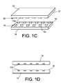
- the matrices 10 may be composed of a bar of square magnets 12a ( FIG. 1A), or an alignment of parallel strips 12b passing through the support 14 (FIG. 1B), or of a regular grid by round magnets 12c of the surface 16 of an element 14 to be joined (FIG. 1C).
- the magnets can be on the surface, or "buried” as in Figure 1D, that is to say that the magnets 12d can be embedded in the support 14, with their level surface with the surface 16 of the support.
- the magnetic means 10, 20 of each may be composed of superposable but polarized matrices conversely so as to attract each other, as schematized in FIGS. 1A and 1B.
- the surfaces 16, 22 to be brought into contact are sufficiently close to allow the magnetic forces generated to position more accurately the dies 10, 20 and thus to generate the self-alignment of the component 18 on the substrate 14.
- the adjustment can thus be greater than 1 ⁇ m. Then, the surfaces 16, 22 are brought into contact in order to maximize the magnetic attraction forces and thus maintain the component 18 and maintain the alignment.
- the geometry of the magnetic compounds 12 of the matrices 10, 20 may be identical, but it may also be slightly different depending on the constraints of space on the faces to be assembled: see for example Figure 1C. It is thus possible to superpose a matrix 10 of round magnets 12c on a matrix 20 of square magnets 12a. It is also possible to choose complementary geometries so as to improve the self-alignment capacity, for example with an annular magnet on one of the components.
- magnetic compound covers not only magnets, but also the various possibilities described above.
- one or both matrices 10, 20 may consist entirely or partially of electromagnets, which makes it possible to electrically control the activation of the magnetic attraction forces.
- a component 32 advantageously in the form of a plate, for example the substrate, comprises a first matrix of electromagnets 34.
- a matrix 36 shifted on the surface 38 to put in contact is planned. This allows a dynamic alignment electrically controlled during or after the removal of the component 40 on the substrate 32 by activating one or other of the matrices 34, 36 of electromagnets.
- the position of the component 40 on the substrate 32 can be corrected during or after the removal.
- FIG. 2 further shows the additional, but not necessary, presence of two sets of magnets 42, 44 on the component 40: it is indeed possible to play on the two elements 32, 40 to be joined, or to provide two possibilities different alignments.
- optical components such as micro-laser chips, lenses, emitters, or mechanical components such as fiber supports optical, or even optoelectronic components with detector arrays.
- the following compounds could be fixed by the process according to the invention: spherical microlens with a diameter of 500 ⁇ m, microlaser chip of 1 mm 3 , micro-mirrors and micro-prisms with a width of 1 mm, laser source of the diode type 1 mm ⁇ 200 ⁇ m, VECSEL type laser source 0.5 mm 2 , ...
- a component plate in particular silicon substrate type used in microelectronics
- the matrices of magnets had steps ranging from 100 microns to 1 mm.
Abstract
Description
L'invention concerne l'assemblage et la fixation des dispositifs miniatures, issus notamment de la microtechnologie. L'invention trouve une application particulière pour l'alignement des différents composants optiques, électriques, mécaniques ou optoélectroniques.The invention relates to the assembly and fixing of miniature devices, especially from microtechnology. The invention finds particular application for the alignment of different optical, electrical, mechanical or optoelectronic components.
Les différents constituants d'un dispositif sont généralement assemblés sur un support ou un substrat par les techniques de serrage mécanique, collage ou brasage. L'application de ces trois procédés aux composants miniatures issus de la microtechnologie, qu'ils soient optiques, électroniques ou mécaniques, présente plusieurs inconvénients.The various constituents of a device are generally assembled on a support or a substrate by the techniques of mechanical clamping, gluing or brazing. The application of these three processes to miniature components derived from microtechnology, whether optical, electronic or mechanical, has several disadvantages.
Le collage par exemple est une technique largement appliquée, notamment avec des colles photoréticulables, car cette technique permet d'aligner les composants avant de les fixer. Cependant, ce procédé peut amener une réduction de la fiabilité des composants par l'intervention d'un composé exogène : par exemple, le dégazage de la colle, et en particulier d'une résine de type époxy, à proximité d'une diode laser est critique à cause de la condensation qui risque de se déposer sur la surface émettrice de la source optique.Bonding, for example, is a widely applied technique, especially with photo-curable adhesives, because this technique makes it possible to align the components before fixing them. However, this process can lead to a reduction in the reliability of the components by the intervention of an exogenous compound: for example, the degassing of the adhesive, and in particular of an epoxy resin, near a laser diode is critical because of the condensation that may be deposited on the emitting surface of the optical source.
Le brasage est également largement appliqué ; il permet notamment l'autoalignement de composants grâce à la technique dite du « flip-chip » : des billes fusibles sont localisées sur des matrices de zones métallisées, et soumises à une élévation de température. La tension de surface des billes en fusion entraîne la superposition des matrices des zones métallisées respectivement réalisées sur le composant et sur son support. En revanche, le brasage nécessite l'utilisation de flux liquides ou gazeux qui peuvent également introduire une réduction de la fiabilité des composants. De plus, le brasage nécessite de chauffer le dispositif au dessus de 100°C, ce qui peut également altérer certains composants.Brazing is also widely applied; it allows in particular the self-alignment of components thanks to the so-called "flip-chip" technique: fusible beads are localized on matrices of metallized zones, and subjected to a rise in temperature. The surface tension of the molten balls causes the superposition of the matrices of the metallized zones respectively made on the component and on its support. On the other hand, soldering requires the use of liquid or gaseous streams which can also introduce a reduction in the reliability of the components. In addition, brazing requires heating the device above 100 ° C, which can also alter some components.
Le serrage mécanique n'altère pas les composants microtechnologiques dans leur nature. Par contre, il nécessite l'introduction de composants volumineux supplémentaires qui viennent encombrer le support du dispositif. Or cette interposition n'est pas toujours possible, en particulier lorsque différents composants doivent être placés à proximité les uns des autres. De plus, la mise en oeuvre de ce type d'assemblage ne permet pas, lors du serrage, de garantir le respect avec précision d'un alignement préalable.Mechanical clamping does not alter microtechnological components in their nature. On the other hand, it requires the introduction of additional bulky components which encumber the support of the device. But this interposition is not always possible, especially when different components must be placed close to each other. In addition, the implementation of this type of assembly does not allow, during tightening, to ensure the accuracy of a prior alignment.
Pour aider à l'alignement, le document U5-A-6 049 947 propose un outillage adapté comprenant des aimants. Cependant, cette structure est longue et lourde à mettre en oeuvre.To aid in alignment, U5-A-6,049,947 proposes a suitable tooling comprising magnets. However, this structure is long and cumbersome to implement.
L'invention se propose donc de trouver un procédé permettant d'assembler, d'aligner (ou d'auto aligner) et de fixer des composants miniatures issus de la microtechnologie sans les inconvénients des techniques connues.The invention therefore proposes to find a method for assembling, aligning (or self-aligning) and fixing miniature components derived from microtechnology without the disadvantages of known techniques.
Sous l'un de ses aspects, l'invention concerne un dispositif microtechnologique comprenant plusieurs éléments assemblés et solidarisés entre eux par l'interaction magnétique de moyens, ou structures, qu'ils comprennent. Grâce à ce choix de fixation, il est possible d'aligner les éléments l'un avec l'autre, tout en n'altérant pas leurs propriétés lors de leur solidarisation.In one of its aspects, the invention relates to a microtechnological device comprising several elements assembled and joined together by the magnetic interaction of means, or structures, that they comprise. With this choice of attachment, it is possible to align the elements with each other, while not altering their properties when joining.
Les éléments peuvent comprendre les différents composants connus de microtechnologie, et notamment l'un des éléments peut être un substrat qui est solidarisé à une plaque de composant ou à un composant ou plusieurs composants différents.The elements may comprise the various known microtechnology components, and in particular one of the elements may be a substrate which is secured to a component plate or a component or several different components.
Il est possible également de solidariser entre eux différents composants. Par composant, il faut comprendre les lentilles, puces laser, émetteurs, composants mécaniques tels que supports de fibre optique ou optoélectroniques par exemple.It is also possible to join together different components. By component, it is necessary to understand the lenses, laser chips, emitters, mechanical components such as fiber optic or optoelectronic supports for example.
Les moyens d'interaction magnétique peuvent comprendre des matériaux magnétisables, des alliages aimantés ou des électroaimants. Il peut s'agir de structures localisées à la surface des éléments qu'elles solidarisent, par exemple par dépôt ou par report de composés individuels. Les moyens pour l'interaction magnétique peuvent être de nature identique ou complémentaire, que ce soit pour la forme et la nature de leurs constituants, ou pour leur géométrie générale.The magnetic interaction means may comprise magnetizable materials, magnetic alloys or electromagnets. It may be localized structures on the surface of the elements that they solidarize, for example by deposit or transfer of individual compounds. The means for the magnetic interaction may be of a nature identical or complementary, whether for the form and nature of their constituents, or for their general geometry.
De préférence, les moyens comprennent des matrices de plusieurs composés susceptibles de générer un champ magnétique de façon à permettre un alignement précis. Il est possible que les matrices soient superposables ; selon un autre mode de réalisation, une structure comprend en outre une deuxième matrice d'électroaimants de façon à permettre un alignement dynamique.Preferably, the means comprise matrices of several compounds capable of generating a magnetic field so as to allow precise alignment. It is possible that the matrices are superimposable; in another embodiment, a structure further comprises a second array of electromagnets so as to provide dynamic alignment.
L'invention concerne également un procédé d'assemblage par interaction magnétique d'éléments d'un dispositif microtechnologique. De préférence, l'assemblage est accompagné par un alignement, passif ou dynamique, des éléments.The invention also relates to a method of assembly by magnetic interaction of elements of a microtechnological device. Preferably, the assembly is accompanied by an alignment, passive or dynamic elements.
Avantageusement, l'étape d'assemblage par interaction magnétique est précédée d'une étape de formation de moyens magnétisables ou aimantés sur les éléments. La formation des moyens magnétiques peut être effectuée par dépôt de couches d'alliages aimantés ou de couches d'électroaimants, ou par report de composés individuels.Advantageously, the assembly step by magnetic interaction is preceded by a step of forming magnetizable or magnetized means on the elements. The formation of the magnetic means can be carried out by deposition of magnetic alloy layers or layers of electromagnets, or by transfer of individual compounds.
Les figures annexées permettront de mieux comprendre l'invention, mais ne sont données qu'à titre indicatif et ne sont nullement restrictives.The appended figures will better understand the invention, but are given for information only and are not restrictive.
Les figures 1A, 1B, 1C et 1D présentent des dispositifs selon l'invention, les deux éléments étant séparés.FIGS. 1A, 1B, 1C and 1D show devices according to the invention, the two elements being separated.
La figure 2 montre une configuration de moyens magnétiques pour un dispositif selon un mode de réalisation de l'invention permettant un alignement dynamique.Figure 2 shows a configuration of magnetic means for a device according to an embodiment of the invention for dynamic alignment.
La figure 3 montre un autre mode de réalisation d'un dispositif selon l'invention.Figure 3 shows another embodiment of a device according to the invention.
L'invention propose d'aligner et de fixer les composants à assembler, par exemple sur un support, grâce à l'interaction magnétique entre des moyens magnétisables qui sont compris dans chacun des éléments à assembler.The invention proposes to align and fix the components to be assembled, for example on a support, thanks to the magnetic interaction between magnetizable means which are included in each of the elements to be assembled.
En effet, certaines techniques rendent possible l'intégration aux éléments à assembler de moyens susceptibles de générer un champ magnétique suffisamment puissant pour solidariser ces éléments. Par ailleurs, les structures ainsi créées gardent une taille compatible avec la microtechnologie.Indeed, certain techniques make it possible to integrate the elements to be assembled means capable of generating a magnetic field powerful enough to secure these elements. Moreover, the structures thus created keep a size compatible with microtechnology.
Ainsi, selon un mode préféré de l'invention, sur un substrat, ou tout autre composant électronique, ou optique, ou optoélectronique, ou micromécanique, ou autre classique en microtechnologie, une zone aimantée, ou magnétisable, ou comprenant des électroaimants, est réalisée, de préférence en surface de façon à améliorer l'alignement. La réalisation peut être effectuée par report de composés unitaires ou par dépôt d'une couche de matériau et technique lithographique d'usinage, par exemple par gravure, sur un substrat :
- 1) Des composés unitaires sont par exemple usinés dans des alliages métalliques de type samarium-cobalt ou aluminium-nickel-cobalt ou néodyme-fer-bore : ces métaux sont dits magnétiques car une fois soumis à un champ magnétique, ils restent fortement aimantés. Les composés sont fabriqués sous la forme adéquate (disques, plaquettes carrées, barrettes allongées,...), puis positionnés sur l'élément à solidariser, si possible selon une géométrie régulière. Ils y sont fixés selon des techniques classiques, par exemple par collage, par adhésion moléculaire, par thermo compression, par brasage, par soudage par laser, ou par faisceau d'électrons.
- 2) Des électro-aimants unitaires sont par exemple réalisés par bobinage de fil de cuivre très fin (dont le diamètre typique est de l'ordre de 50 µm). Ces composés pourront être reportés sur un substrat, de type circuit imprimé ou céramique métallisée, afin de connecter les électro-aimants au système de commande via des pistes électriques. La même mise en place que pour l'exemple 1 ci-dessus peut être réalisée.
- 3) Des matériaux magnétiques de type cobalt-platine ou cobalt-platine-phosphore ou nickel-fer peuvent par ailleurs être mis en place directement sur l'élément à solidariser par dépôt électrolytique ou dépôt plasma en phase vapeur (PVD). Les zones aimantées ainsi réalisées peuvent être structurées géométriquement par les techniques lithographiques issues de la microélectronique, par exemple par gravure. Ce type de procédé permet de générer des épaisseurs de plusieurs micromètres.
- 4) Il est possible également de déposer sur une surface de composant microtechnologique des résines chargées en poudre de matériaux magnétiques, afin de réaliser des motifs de plusieurs dizaines de micromètres d'épaisseur (voir par exemple Cho HJ et Ahn CH : « Microscale resin-bonded permanent magnets for magnetic micro-electro-mechanical systems applications », Journal of Applied Physics 2003 ; 93(10) : 8674-76).
- 5) Un dépôt d'électroaimants en multicouche peut être réalisé par technique lithographique de façon à obtenir une forme proche de la bobine avec un matériau tel que le cuivre. Dans cette configuration, les pistes électriques connectant les électro-aimants au système de commande sont généralement réalisées sur le substrat par les mêmes techniques.
- 6) D'autres procédés sont envisageables pour augmenter l'épaisseur des « micro aimants » si cela est préféré. Par exemple le dépôt par laser pulsé du Nd-Fe-B permet d'atteindre des épaisseurs de l'ordre de 40 à 50 µm (Nakano M et coll. : « Fabrication of Nd-Fe-B thick film magnets by high speed PLD method », IEEE Transaction on Magnetics 2003 ; 39(5) : 2863-65).
- 1) Unit compounds are for example machined in metal alloys samarium-cobalt or aluminum-nickel-cobalt or neodymium-iron-boron: these metals are called magnetic because once subjected to a magnetic field, they remain strongly magnetized. The compounds are manufactured in the appropriate form (disks, square plates, elongate bars, ...), then positioned on the element to be joined, if possible according to a regular geometry. They are fixed there according to conventional techniques, for example by gluing, by molecular adhesion, by thermo-compression, by brazing, by laser welding, or by electron beam.
- 2) Unit electromagnets are for example made by winding very thin copper wire (whose typical diameter is of the order of 50 microns). These compounds may be transferred to a substrate, printed circuit type or metallized ceramic, in order to connect the electromagnets to the control system via electrical tracks. The same setting as for example 1 above can be performed.
- 3) Magnetic materials of cobalt-platinum or cobalt-platinum-phosphorus or nickel-iron type may also be placed directly on the element to be joined by electroplating or plasma vapor deposition (PVD). The magnetized zones thus produced may be geometrically structured by lithographic techniques derived from microelectronics, for example by etching. This type of process makes it possible to generate thicknesses of several micrometers.
- 4) It is also possible to deposit on a surface of microtechnological component powdered resins of magnetic materials, in order to produce patterns of several tens of micrometers in thickness (see for example Cho HJ and Ahn CH: "Microscale resin- bonded permanent magnets for magnetic micro-electro-mechanical systems applications ", Journal of Applied Physics 2003; 93 (10): 8674-76).
- 5) A deposit of multilayer electromagnets can be achieved by lithographic technique so as to obtain a shape close to the coil with a material such as copper. In this configuration, the electrical tracks connecting the electromagnets to the control system are generally performed on the substrate by the same techniques.
- 6) Other methods are possible to increase the thickness of "micro magnets" if this is preferred. For example, the pulsed laser deposition of Nd-Fe-B makes it possible to reach thicknesses of the order of 40 to 50 μm (Nakano M et al .: "Fabrication of Nd-Fe-B thick film magnets by high speed PLD method ", IEEE Transaction on Magnetics 2003; 39 (5): 2863-65).
Ces différents procédés de réalisation permettent d'obtenir des zones susceptibles de créer des champs magnétiques de taille réduite, mais dont la puissance est suffisante pour maintenir en place un composant microtechnologique. En particulier, les aimants obtenus par technique de report (1 et 2) peuvent avoir classiquement une surface de l'ordre de 1 mm2 pour une hauteur de 0,5 mm, et peuvent aisément être mis en place avec un pas de l'ordre du mm. En ce qui concerne les technologies microélectroniques, on peut avoir des aimants de surface inférieure à 0,5 x 0,5 mm2 pour une hauteur de 5 à 50 µm, avec un pas de 100 µm par exemple.These different production methods make it possible to obtain areas that are capable of creating magnetic fields of small size, but whose power is sufficient to keep a microtechnological component in place. In particular, the magnets obtained by transfer technique (1 and 2) can conventionally have a surface of the order of 1 mm 2 for a height of 0.5 mm, and can easily be put in place with a step of the order of mm. With regard to microelectronic technologies, it is possible to have magnets with a surface area of less than 0.5 × 0.5 mm 2 for a height of 5 to 50 μm, with a pitch of 100 μm, for example.
Ainsi par exemple, un dépôt électrolytique CoPt permet la réalisation d'un aimant d'environ 100 µm2 sur 5 µm d'épaisseur, générant une force de l'ordre de quelques N, soit plusieurs mg/mm2. Une telle force est suffisante pour des composants miniatures : typiquement un morceau de silicium de 1 mm2 sur 0,5 mm d'épaisseur pèse environ 1 mg.For example, an electrolytic deposit CoPt allows the realization of a magnet of about 100 microns 2 by 5 microns thick, generating a force of the order of a few N, several mg / mm 2 . Such a force is sufficient for miniature components: typically a piece of silicon 1 mm 2 by 0.5 mm thick weighs about 1 mg.
De préférence, les zones ainsi créées forment des moyens magnétiques, ou des structures, qui se présentent sous la forme de matrices, comme schématisé en figure 1. En particulier, les matrices 10 peuvent être composées d'une barrette d'aimants carrés 12a (figure 1A), ou d'un alignement de bandes parallèles 12b traversant le support 14 (figure 1B), ou d'un quadrillage régulier par des aimants ronds 12c de la surface 16 d'un élément 14 à solidariser (figure 1C). Les aimants peuvent être en surface, ou « enterrés » comme sur la figure 1D, c'est-à-dire que les aimants 12d peuvent être enchâssés dans le support 14, avec leur surface de niveau avec la surface 16 du support.Preferably, the zones thus created form magnetic means, or structures, which are in the form of matrices, as shown schematically in FIG. 1. In particular, the
De façon préférée, lorsqu'un composant 18 est prévu pour être solidarisé sur un substrat 14, les moyens magnétiques 10, 20 de chacun peuvent être composés de matrices superposables mais polarisées inversement de façon à s'attirer entre-elles, comme schématisé sur les figures 1A et 1B.Preferably, when a
Lors de l'assemblage des deux éléments 14, 18, après un réglage grossier permettant de superposer approximativement les matrices 10, 20, les surfaces 16, 22 à mettre en contact sont approchées de façon suffisante pour permettre aux forces magnétiques générées de positionner plus précisément les matrices 10, 20 et ainsi de générer l'auto alignement du composant 18 sur le substrat 14. L'ajustement peut ainsi être supérieur à 1 µm. Ensuite, les surfaces 16, 22 sont mises en contact afin de maximiser les forces d'attraction magnétique et ainsi maintenir le composant 18 et conserver l'alignement.When assembling the two
Il est clair que sur les figures, les dimensions ne sont pas à l'échelle en ce qui concerne les épaisseurs des aimants. De plus, selon l'application, les éléments seront en relief sur la surface de l'élément, ou enterrés (figure 1D) pour affleurer la surface 16, et ainsi pouvoir ajuster le jeu entre les éléments 14, 18.It is clear that in the figures, the dimensions are not to scale with respect to the thickness of the magnets. In addition, depending on the application, the elements will be embossed on the surface of the element, or buried (Figure 1D) to flush the
La géométrie des composés magnétiques 12 des matrices 10, 20 peut être identique, mais elle peut également être légèrement différente selon les contraintes d'encombrement sur les faces à assembler : voir par exemple figure 1C. On peut ainsi superposer une matrice 10 d'aimants ronds 12c sur une matrice 20 d'aimants carrés 12a. Il est possible également de choisir des géométries complémentaires de façon à améliorer la capacité d'auto alignement, par exemple avec un aimant annulaire sur l'un des composants.The geometry of the magnetic compounds 12 of the
Il est entendu que dans ces exemples, le terme « composé magnétique » recouvre non seulement des aimants, mais également les différentes possibilités décrites plus haut. En particulier, une ou les deux matrices 10, 20 peuvent être constituées, entièrement ou partiellement, d'électroaimants, ce qui permet de commander électriquement l'activation des forces d'attraction magnétique.It is understood that in these examples, the term "magnetic compound" covers not only magnets, but also the various possibilities described above. In particular, one or both
Un exemple particulier de ce type de configuration est donné dans le dispositif 30 représenté en figure 2. Un composant 32, avantageusement sous forme de plaque, par exemple le substrat, comporte une première matrice d'électroaimants 34. Une matrice 36 décalée sur la surface 38 à mettre en contact est prévue. Ceci permet de réaliser un alignement dynamique commandé électriquement pendant ou après la dépose du composant 40 sur le substrat 32 en activant l'une ou l'autre des matrices 34, 36 d'électro-aimants. Ainsi, la position du composant 40 sur le substrat 32 peut être corrigée pendant, ou également après, la dépose.A particular example of this type of configuration is given in the
La figure 2 montre en outre la présence additionnelle, mais non nécessaire, de deux jeux d'aimants 42, 44 sur le composant 40 : il est en effet possible de jouer sur les deux éléments 32, 40 à solidariser, ou de prévoir deux possibilités d'alignements différents.FIG. 2 further shows the additional, but not necessary, presence of two sets of
Pour un tel alignement dynamique, il est également possible de combiner les natures des moyens magnétiques, et de réaliser un système mixte d'alignement passif et actif de façon à permettre des corrections fines de positionnement, en remplaçant par exemple l'une des matrices d'électroaimants 34, 36 ou 42, 44 par une matrice de composés aimantés.For such a dynamic alignment, it is also possible to combine the natures of the magnetic means, and to realize a mixed passive and active alignment system so as to allow fine positioning corrections, for example by replacing one of the matrices of
Les techniques de positionnement et d'assemblage décrites peuvent être appliquées à toute sorte de composants : on peut associer, au substrat ou entre eux, des composants optiques tels que puces micro laser, lentilles, émetteurs, ou des composants mécaniques comme des supports de fibre optique, voire des composants optoélectroniques avec les matrices de détecteurs.The positioning and assembly techniques described can be applied to all kinds of components: one can associate, to the substrate or between them, optical components such as micro-laser chips, lenses, emitters, or mechanical components such as fiber supports optical, or even optoelectronic components with detector arrays.
Il est possible aussi, en combinant la géométrie des aimants, d'assembler des composés de natures différentes sur un même support : voir le dispositif 50 de la figure 3 qui présente l'assemblage d'une lentille 52 et d'une puce laser 54 sur un même substrat 56 au moyen de moyens aimantés présentant des matrices 58, 60 différentes.It is also possible, by combining the geometry of the magnets, to assemble compounds of different natures on the same support: see the
Par exemple, les composés suivants ont pu être fixés par le procédé selon l'invention : microlentille sphérique de diamètre 500 µm, puce microlaser de 1 mm3, micro-miroirs et micro-prismes de largeur 1 mm, source laser de type diode de 1 mm x 200 µm, source laser de type VECSEL de 0,5 mm2,... De même, il a été possible de positionner de façon fixe une plaque de composant (en particulier de type substrat de silicium utilisé en microélectronique) de 1 à 30 cm de côté pour une épaisseur de 500 µm. Pour ces différentes réalisations, les matrices d'aimants avaient des pas pouvant aller de 100 µm à 1 mm.For example, the following compounds could be fixed by the process according to the invention: spherical microlens with a diameter of 500 μm, microlaser chip of 1 mm 3 , micro-mirrors and micro-prisms with a width of 1 mm, laser source of the diode type 1 mm × 200 μm, VECSEL type laser source 0.5 mm 2 , ... Similarly, it was possible to position fixedly a component plate (in particular silicon substrate type used in microelectronics) of 1 to 30 cm side for a thickness of 500 microns. For these different embodiments, the matrices of magnets had steps ranging from 100 microns to 1 mm.
Le procédé d'alignement et d'assemblage selon l'invention présente, entre autres, les avantages suivants :
- la fixation des composants grâce aux forces magnétiques, contrairement au collage et au brasage, ne nécessite aucune application de flux liquide ou gazeux, aucune montée en température, et ne génère aucun risque de dégazage qui pourrait réduire la fiabilité des composants ;
- il est possible d'auto aligner le composant sur le support, à la manière d'un « flip-chip » magnétique ;
- l'activation des forces magnétiques peut être effectuée à la demande et avec retard, par commande électrique ;
- un alignement dynamique du composant sur le support et une correction de la position du composant sur le support sont possibles ;
- la conduction thermique et électrique au sein du dispositif microtechnologique est améliorée grâce au contact métal/métal par les moyens susceptibles de produire un champ magnétique ;
- il est possible de positionner avec précision et de fixer plusieurs composants sur un même substrat.
- the fixing of components by magnetic forces, unlike gluing and brazing, requires no application of liquid or gaseous flow, no rise in temperature, and does not generate any risk of degassing that could reduce the reliability of the components;
- it is possible to self-align the component on the support, in the manner of a magnetic "flip-chip";
- activation of the magnetic forces can be carried out on demand and with delay, by electric control;
- a dynamic alignment of the component on the support and a correction of the position of the component on the support are possible;
- the thermal and electrical conduction within the microtechnological device is improved thanks to the metal / metal contact by the means capable of producing a magnetic field;
- it is possible to precisely position and fix several components on the same substrate.
Claims (21)
Applications Claiming Priority (1)
| Application Number | Priority Date | Filing Date | Title |
|---|---|---|---|
| FR0451688A FR2873675B1 (en) | 2004-07-28 | 2004-07-28 | MICROTECHNOLOGICAL DEVICE COMPRISING MAGNETICALLY ASSEMBLED STRUCTURES AND ASSEMBLY METHOD |
Publications (1)
| Publication Number | Publication Date |
|---|---|
| EP1621516A1 true EP1621516A1 (en) | 2006-02-01 |
Family
ID=34948639
Family Applications (1)
| Application Number | Title | Priority Date | Filing Date |
|---|---|---|---|
| EP05106846A Withdrawn EP1621516A1 (en) | 2004-07-28 | 2005-07-26 | Microtechnological device with magnetically assembled structures and assembling method |
Country Status (4)
| Country | Link |
|---|---|
| US (1) | US20060022784A1 (en) |
| EP (1) | EP1621516A1 (en) |
| JP (1) | JP2006041534A (en) |
| FR (1) | FR2873675B1 (en) |
Families Citing this family (5)
| Publication number | Priority date | Publication date | Assignee | Title |
|---|---|---|---|---|
| WO2007023327A1 (en) * | 2005-08-24 | 2007-03-01 | Infineon Technologies Ag | Magnetically alignable semiconductor chip and rewiring substrate and a method for magnetically aligning the semiconductor chip and the rewiring substrate |
| JP2012256737A (en) | 2011-06-09 | 2012-12-27 | Sony Corp | Semiconductor device and manufacturing method therefor |
| US20130199831A1 (en) * | 2012-02-06 | 2013-08-08 | Christopher Morris | Electromagnetic field assisted self-assembly with formation of electrical contacts |
| US9711443B2 (en) * | 2015-11-14 | 2017-07-18 | Intel Corporation | Magnetic alignment for flip chip microelectronic devices |
| CN111128790B (en) * | 2018-10-31 | 2022-08-30 | 成都辰显光电有限公司 | Micro-element processing device, welding method and display panel |
Citations (1)
| Publication number | Priority date | Publication date | Assignee | Title |
|---|---|---|---|---|
| EP1215168A1 (en) * | 2000-12-07 | 2002-06-19 | Agere Systems Guardian Corporation | Magnetically packaged optical mems device and method for making the same |
Family Cites Families (4)
| Publication number | Priority date | Publication date | Assignee | Title |
|---|---|---|---|---|
| US3612955A (en) * | 1969-01-21 | 1971-10-12 | Bell Telephone Labor Inc | Circuit board containing magnetic means for positioning devices |
| US6049974A (en) * | 1998-04-29 | 2000-04-18 | National Semiconductor Corporation | Magnetic alignment apparatus and method for self-alignment between a die and a substrate |
| US6480347B1 (en) * | 2000-09-14 | 2002-11-12 | Leica Microsystems Inc. | Device for reproducible positioning of optical surfaces |
| US6340302B1 (en) * | 2001-02-06 | 2002-01-22 | Micron Technology, Inc. | Apparatus for establishing an electrical connection with a wafer to facilitate wafer-level burn-in and methods |
-
2004
- 2004-07-28 FR FR0451688A patent/FR2873675B1/en not_active Expired - Fee Related
-
2005
- 2005-07-26 EP EP05106846A patent/EP1621516A1/en not_active Withdrawn
- 2005-07-26 US US11/190,706 patent/US20060022784A1/en not_active Abandoned
- 2005-07-27 JP JP2005218019A patent/JP2006041534A/en active Pending
Patent Citations (1)
| Publication number | Priority date | Publication date | Assignee | Title |
|---|---|---|---|---|
| EP1215168A1 (en) * | 2000-12-07 | 2002-06-19 | Agere Systems Guardian Corporation | Magnetically packaged optical mems device and method for making the same |
Non-Patent Citations (2)
| Title |
|---|
| CHO HJ; AHN CH: "Microscale resin-bonded permanent magnets for magnetic micro-electro-mechanical systems applications", JOURNAL OF APPLIED PHYSICS, vol. 93, no. 10, 2003, pages 8674 - 76 |
| NAKANO M: "Fabrication of Nd- Fe-B thick film magnets by high speed PLD method", IEEE TRANSACTION ON MAGNETICS, vol. 39, no. 5, 2003, pages 2863 - 65 |
Also Published As
| Publication number | Publication date |
|---|---|
| US20060022784A1 (en) | 2006-02-02 |
| FR2873675B1 (en) | 2006-09-22 |
| JP2006041534A (en) | 2006-02-09 |
| FR2873675A1 (en) | 2006-02-03 |
Similar Documents
| Publication | Publication Date | Title |
|---|---|---|
| EP3625822B1 (en) | Method of manufacturing an emissive led display device | |
| EP2279524B1 (en) | Method of producing an optical device consisting of integrated optoelectronic components | |
| EP2054929B1 (en) | Process for the collective manufacturing of electronic 3d modules | |
| EP3389091A1 (en) | Method for manufacturing an led emissive display and resulting led emissive display | |
| US4457467A (en) | Method for positioning and fixing optical components relative to one another | |
| EP1621516A1 (en) | Microtechnological device with magnetically assembled structures and assembling method | |
| JPH04230088A (en) | Manufacture of optical module | |
| EP2441088B1 (en) | Method for positioning chips during the production of a reconstituted wafer | |
| CN111295608B (en) | Optical assembly | |
| WO2021099713A1 (en) | Method for manufacturing a functional chip suitable for being assembled to wire elements | |
| EP0944851B1 (en) | Assembly of optical components optically aligned and method for making this assembly | |
| EP3329511B1 (en) | Method for direct bonding with self-alignment using ultrasound | |
| US7372618B2 (en) | Method of manufacturing micromirror array and method of manufacturing optical device having micromirror | |
| FR2959350A1 (en) | METHOD FOR MANUFACTURING A MICROELECTRONIC DEVICE AND MICROELECTRONIC DEVICE SO MANUFACTURED | |
| EP3182450A1 (en) | Inductance device and method for manufacturing same | |
| EP1864743B1 (en) | Assembly and method of assembly by brazing of an object and a support | |
| US6543114B2 (en) | Manufacturing system using solder self-alignment with optical component deformation fine alignment | |
| EP2684434B1 (en) | Process for flip-chip connection of an electronic component | |
| EP1427008B1 (en) | Process of manufacturing an electronic module comprising an active component on a substrate | |
| EP1429166B1 (en) | Optical arrangement with two optical inputs/outputs and a method of manufacturing | |
| WO2002035138A1 (en) | Method for passive alignment of supports, particularly plates bearing optical components | |
| EP1272350B1 (en) | High density element structure formed by assembly of layers and method for making same | |
| EP2246890B1 (en) | Method of fabrication of an imager module | |
| EP3031775A1 (en) | Method for producing an electrical connection in a blind via and electrical connection obtained | |
| FR2859045A1 (en) | DEVICE FOR ELECTRICALLY CONNECTING BETWEEN TWO PLATES AND METHOD FOR PRODUCING A MICROELECTRONIC COMPONENT COMPRISING SUCH A DEVICE |
Legal Events
| Date | Code | Title | Description |
|---|---|---|---|
| PUAI | Public reference made under article 153(3) epc to a published international application that has entered the european phase |
Free format text: ORIGINAL CODE: 0009012 |
|
| AK | Designated contracting states |
Kind code of ref document: A1 Designated state(s): AT BE BG CH CY CZ DE DK EE ES FI FR GB GR HU IE IS IT LI LT LU LV MC NL PL PT RO SE SI SK TR |
|
| AX | Request for extension of the european patent |
Extension state: AL BA HR MK YU |
|
| AKX | Designation fees paid | ||
| REG | Reference to a national code |
Ref country code: DE Ref legal event code: 8566 |
|
| STAA | Information on the status of an ep patent application or granted ep patent |
Free format text: STATUS: THE APPLICATION IS DEEMED TO BE WITHDRAWN |
|
| 18D | Application deemed to be withdrawn |
Effective date: 20060802 |