EP1621380A2 - Curved roller blind with abutment for a spring - Google Patents
Curved roller blind with abutment for a spring Download PDFInfo
- Publication number
- EP1621380A2 EP1621380A2 EP05014625A EP05014625A EP1621380A2 EP 1621380 A2 EP1621380 A2 EP 1621380A2 EP 05014625 A EP05014625 A EP 05014625A EP 05014625 A EP05014625 A EP 05014625A EP 1621380 A2 EP1621380 A2 EP 1621380A2
- Authority
- EP
- European Patent Office
- Prior art keywords
- cap
- roller blind
- spring
- axis
- shaft
- Prior art date
- Legal status (The legal status is an assumption and is not a legal conclusion. Google has not performed a legal analysis and makes no representation as to the accuracy of the status listed.)
- Withdrawn
Links
Images


Classifications
-
- B—PERFORMING OPERATIONS; TRANSPORTING
- B60—VEHICLES IN GENERAL
- B60J—WINDOWS, WINDSCREENS, NON-FIXED ROOFS, DOORS, OR SIMILAR DEVICES FOR VEHICLES; REMOVABLE EXTERNAL PROTECTIVE COVERINGS SPECIALLY ADAPTED FOR VEHICLES
- B60J1/00—Windows; Windscreens; Accessories therefor
- B60J1/20—Accessories, e.g. wind deflectors, blinds
- B60J1/2011—Blinds; curtains or screens reducing heat or light intensity
- B60J1/2013—Roller blinds
- B60J1/2019—Roller blinds powered, e.g. by electric, hydraulic or pneumatic actuators
- B60J1/2027—Roller blinds powered, e.g. by electric, hydraulic or pneumatic actuators with a buckle-proof guided flexible actuating element acting on the draw bar for pushing or push-pulling, e.g. a Bowden cable
-
- B—PERFORMING OPERATIONS; TRANSPORTING
- B60—VEHICLES IN GENERAL
- B60J—WINDOWS, WINDSCREENS, NON-FIXED ROOFS, DOORS, OR SIMILAR DEVICES FOR VEHICLES; REMOVABLE EXTERNAL PROTECTIVE COVERINGS SPECIALLY ADAPTED FOR VEHICLES
- B60J1/00—Windows; Windscreens; Accessories therefor
- B60J1/20—Accessories, e.g. wind deflectors, blinds
- B60J1/2011—Blinds; curtains or screens reducing heat or light intensity
- B60J1/2013—Roller blinds
- B60J1/2033—Roller blinds characterised by the spring motor
-
- B—PERFORMING OPERATIONS; TRANSPORTING
- B60—VEHICLES IN GENERAL
- B60J—WINDOWS, WINDSCREENS, NON-FIXED ROOFS, DOORS, OR SIMILAR DEVICES FOR VEHICLES; REMOVABLE EXTERNAL PROTECTIVE COVERINGS SPECIALLY ADAPTED FOR VEHICLES
- B60J1/00—Windows; Windscreens; Accessories therefor
- B60J1/20—Accessories, e.g. wind deflectors, blinds
- B60J1/2011—Blinds; curtains or screens reducing heat or light intensity
- B60J1/2013—Roller blinds
- B60J1/2036—Roller blinds characterised by structural elements
-
- B—PERFORMING OPERATIONS; TRANSPORTING
- B60—VEHICLES IN GENERAL
- B60J—WINDOWS, WINDSCREENS, NON-FIXED ROOFS, DOORS, OR SIMILAR DEVICES FOR VEHICLES; REMOVABLE EXTERNAL PROTECTIVE COVERINGS SPECIALLY ADAPTED FOR VEHICLES
- B60J1/00—Windows; Windscreens; Accessories therefor
- B60J1/20—Accessories, e.g. wind deflectors, blinds
- B60J1/2011—Blinds; curtains or screens reducing heat or light intensity
- B60J1/2013—Roller blinds
- B60J1/2066—Arrangement of blinds in vehicles
- B60J1/2075—Arrangement of blinds in vehicles specially adapted for fixed windows
- B60J1/208—Arrangement of blinds in vehicles specially adapted for fixed windows for rear windows
-
- B—PERFORMING OPERATIONS; TRANSPORTING
- B60—VEHICLES IN GENERAL
- B60J—WINDOWS, WINDSCREENS, NON-FIXED ROOFS, DOORS, OR SIMILAR DEVICES FOR VEHICLES; REMOVABLE EXTERNAL PROTECTIVE COVERINGS SPECIALLY ADAPTED FOR VEHICLES
- B60J3/00—Antiglare equipment associated with windows or windscreens; Sun visors for vehicles
- B60J3/002—External sun shield, e.g. awning or visor
- B60J3/005—External sun shield, e.g. awning or visor for side windows
-
- B—PERFORMING OPERATIONS; TRANSPORTING
- B60—VEHICLES IN GENERAL
- B60Y—INDEXING SCHEME RELATING TO ASPECTS CROSS-CUTTING VEHICLE TECHNOLOGY
- B60Y2200/00—Type of vehicle
- B60Y2200/10—Road Vehicles
- B60Y2200/11—Passenger cars; Automobiles
Definitions
- the endeavor is therefore also to create curved Wickewellen, as shown for example in DE 103 38 900 A1.
- the actual winding shaft which is connected to the roller blind, consists of a number of straight shaft sections which are rotatably coupled together.
- the shaft sections are rotatably mounted together on a curved axis.
- the axle is clamped at one end to anchor it in the circumferential direction and in the axial direction.
- the other end is supported by means of a rotatably mounted on the cap cap, which passes through the cap through a spring rod, which is also fixed rigidly outside the axis.
- the spring rod carries at its in-axis end of the rigid spring abutment, while the outer spring abutment is anchored to the cap.
- the new window blind has a single axis rigidly anchored curved axis.
- the axis is, at least at one end, tubular.
- the winding shaft is rotatably mounted, which is composed of at least a shaft portion and a cap.
- the cap is also part of the bearing means of the axle and abutment for the spring.
- the cap is rotatably mounted on corresponding long-term agents and thus captivates the free end of the axle in the radial direction.
- the stationary spring abutment is seated in the at least partially tubular winding shaft.
- the axis itself becomes the stationary abutment for the spring motor.
- the existing in the prior art spring rod can be saved. Since the spring, which forms the spring motor, is flexible, it can be arbitrarily adapted to the curvature of the axis. In particular, it can create on the inside of the curvature on the axis, which contributes to the reduction of rattling noises. Forced positions between spring and axle and spring rod, as is the case in the prior art, are avoided.
- the axial bias that can generate the spring motor is simultaneously used to bias the tubular winding shaft together with cap in the axial direction.
- the individual shaft sections lie spielfei each other.
- the abutment can be formed in the simplest case by a flange which is produced by upsetting the tubular axis.
- the cap which is used to transmit the force from the spring motor to the shaft portions, may either have the shape of a flat disc with a corresponding driving toothing for the shaft portions, or be a cap with a bottom and a molded collar, with it is itself mounted on the outer peripheral surface of the axle.
- the cap is provided on its side adjacent to the rigid axle with a spring abutment, in which the spring spring serving as a helical spring is anchored rotationally fixed and axially secured.
- the fixed spring abutment consists of an insert, which is used in the rigid axis and there, for example, pressed by beads.
- Figure 1 illustrates the broken, cut-off rear region of a passenger car.
- the figure illustrates a view of the right inner side, which is a mirror image of the unillustrated left inner side.
- the presentation is simplified.
- interior body structures such as stiffening and fasteners are not shown because their representation for understanding the invention is not required.
- the representation of the body is schematic and does not recognize the existing cavities there.
- the illustrated body section 1 has a roof 2, from the side of a B-pillar 3 leads down to a bottom group, not shown. A corresponding B-pillar would be conceivable on the broken-off side of the vehicle.
- the roof 2 merges at its rear edge into a rear window 4. Laterally, the rear window ends at a C-pillar 5, which is located at a distance from the B-pillar 3.
- the C-pillar 5 carries an inner lining 6.
- a rear, right side door 7 is hinged to the B pillar 3 in a known manner.
- right side door 7 is a setback 8, to which a seat 9 and a rear seat back 11 belong.
- the rear seat 9 lies on a base surface 12 which belongs to the floor assembly and are formed in front of the foot wells 13.
- a rear shelf 15 extends to the lower edge of the rear window. 4
- the rear, right side door is provided in the usual manner for sedans with a side window 16.
- rear window roller blind 16 On the inside in front of the rear window 4 there is a rear window roller blind 16. Of the rear window roller blind 16 is partially extended roller blind 17 and one of lateral guide rails 18 can be seen.
- the guide rail 18 begins at the existing behind the rear seat backrest 11 shelf 15 and runs next to the side edge of the window.
- the parcel shelf 15 includes a continuous pull-out slot 20, from which the roller blind 18 runs out.
- the extension slot 20 is curved to approximate the curvature of the rear window 4.
- a curved winding shaft 21 is rotatably mounted on the blind sheet 18 is attached with an edge.
- the representation of the winding shaft 21 is highly schematic in Fig. 2, the details will be apparent from the following figures.
- the winding shaft 21 is biased by means of a schematically indicated spring motor 22 in the sense of winding the roller blind 18 on the winding shaft 21.
- a helical spring is provided, which is anchored at one end to the body and fixed at the other end in the winding shaft 21.
- the curvature of the winding shaft 21 corresponds to the curvature of the extension slot 20th
- the roller blind 17 has an approximately trapezoidal blank and is provided on its edge remote from the winding shaft 21 with a tubular loop 23. Through the tubular loop 23 performs a pull-out profile or bow, in the end pieces 24 and 25 telescopically are stored.
- the end pieces 24 and 25 have a neck portion 26 which has a smaller diameter than an adjoining guide member 27 which has the shape of a short cylindrical portion.
- the guide members 27 run in the guide rails 19, which are arranged adjacent to the two side edges of the rear window 4.
- the extended roller blind 18 Since both the winding shaft 21 and the extension profile are curved in the same way, the extended roller blind 18 describes a curved surface whose generatrix is a straight line. If possible, the blind sheet 18 does not brush against the edges of the pull-out slot 18.
- Each of the guide rails 19 includes an undercut guide groove 28 which opens in the direction of the roller blind 18 in a guide slot.
- each guide rail 19 is connected to a guide tube 29, 30, in which two bendable push members 31 and 32 are guided ausknickêt.
- the flexible thrust members 31 and 32 are so-called SU flexwellen. They consist of a cylindrical core, which is surrounded by a helically extending rib. In this way, a kind of flexible racks with all-round toothing is obtained.
- the guide tubes 29 and 30 connect the guide rails 19 with a geared motor 33.
- the geared motor 33 is composed of a permanent magnet DC motor 34 and a gear 35 together on the output shaft 36, a spur gear 37 rotatably seated.
- the gear 37 meshes with the two push members 31, 32 positively.
- the Thrust members 31, 32 pass tangentially to the diametrically opposite sides of the spur gear 37 and are guided for this purpose in corresponding bores 38, 39.
- the thrust members 31, 32 are selectively advanced or retracted.
- the movement of the thrust members 31, 32 follow the guide pieces 24, 25. These are held by means of the spring motor 22 against the free ends of the thrust members 31, 32 fitting, which are located in the guide grooves 28.
- the winding shaft 21 is, as the enlarged view reveals, composed of a plurality of axially adjacent tubular shaft portions 40 together.
- the rohrfömigen shaft sections 40 are positively coupled together at the joints at 41.
- the shaft portions on the front side tabs between which recesses or recesses are included which have the same shape as the tabs, such that the tabs on one side into the recesses on the opposite side of the other shaft portion 40 can intervene.
- this positive connection gives the possibility that the individual shaft sections 40 can tilt against each other, so as to approximate the desired curved course of the winding shaft 21 in a polygonal manner.
- the shaft sections 40 sit one behind the other on a tubular axis 42.
- the axis 42 is compressed at one end in FIG. 4 in the axial direction, whereby a radially outwardly projecting flange 43 is formed, which serves as an abutment for the immediately adjacent shaft portion 40.
- the wall material that forms the tubular axis 42 in the region of the flange 43 is double-layered.
- the remaining tubular part which adjoins the flange 43 is pressed flat, whereby a flat fastening plate is formed, with an opening 45 for a fastening element 46, for example a screw, a rivet or the like.
- the mounting plate 44 is formed by the forming integral part of the rohrfömigen axis 42nd
- the tubular shaft portions 40 are provided with inwardly projecting warts 47.
- the warts 47 each form groups, with the warts within a group lying on a circle concentric with the axis of the shaft portion 40. In each case a group of these warts 47 is provided in the vicinity of the respective front end of the shaft portion 40, as can be seen in the shaft portions 40 shown in full.
- the tubular shaft portion 40 is high in the area between the warts 47 at the two ends and is only in contact with the tubular axis 42 via the warts 47.
- a curvature of the tubular axis in the region between the ends of the tubular shaft portions 40 does not result in jamming.
- the schematically indicated spring motor 22 consists of a helical spring.
- the coil spring 22 is anchored at its end 48 in an abutment 49 which is inserted in the tubular axis 42. He is there pressed with the help of a bead 51, so that he can neither move in the axial direction nor can rotate. In the region of the bead 51, the spring abutment 49 is provided with a corresponding constriction.
- the spring abutment 49 carries in the direction of the spring 22 a short pin 52 with a transverse hole in which the spring end 48 is mounted.
- the other spring end 53 is coupled with a cup-shaped cap 54.
- the cup-shaped cap 54 is composed of a bottom 55 and an adjoining short collar 56.
- the collar 56 is provided at its free end face with the same coupling teeth as the adjacent shaft portion 40 so that a positive coupling between the cup-shaped cap 54 and the adjacent shaft portion 40 is made.
- the bottom 55 carries on its side adjacent to the tubular axis 42 a pin-shaped extension 57, in which the spring end 53 is hooked.
- a bearing pin 60 protrudes, which is firmly anchored in the body.
- the winding shaft 21 is biased in the sense of winding the blind sheet 18.
- the coil spring 22 is supported via the fixed spring abutment 49 in the body via the tubular axis 52 firmly held there.
- the other end of the coil spring 22 is rotatably coupled via the cup-shaped cap 54 with the adjacent tubular shaft portion 40, which in turn is connected without play or play with the wave portion 40 adjacent thereto. In this way, the torque generated by the coil spring 22 is transmitted to all shaft sections 40.
- the coil spring 22 is anchored not only in the rotational sense of the spring abutment 49 and the cup-shaped cap 54, but also fixed in the axial direction.
- the spring abutment 49 can thus be ensured that the coil spring 22 not only generates the drive torque, but also exerts a pulling force on the cup-shaped cap 54 to push the sequence of tubular shaft portions 40 frontally against each other.
- the reaction force is finally absorbed by the flange 43.
- the stationary bearing pin 60 in the blind hole 59 playfully engages is also free auskragnede in the end of the tubular shaft 40, which is not immediate bolted to the body, guided in the radial direction. All of the radial forces transmitted from the winding shaft 21 to the tubular axle 40 are introduced at one end via the plate 44 directly and at the other end by means of the rotatably mounted cup-shaped cap 54 into the body.
- a spring motor In a roller blind with a curved winding shaft, a spring motor is used in which a spring abutment is fixed within and on the axis on which the individual segments of the winding shaft are rotatably mounted. As a result, a mounting relief is created and the spring is able to apply to the wall of the axle to avoid rattling noises.
Abstract
Description
Bei modernen Karosserien geht die Tendenz weg von flach gekrümmten Heckscheiben in Richtung auf Heckscheiben mit starker Krümmung gegenüber der Hochachse. Solche Heckfenster lassen sich mit Fensterrollos, die eine gerade Wickelwelle aufweisen, nur schlecht abschatten. Das gerade Fensterrollo liegt sozusagen als Sehne vor der stark gekrümmten Heckscheibe und hat dementsprechend in der Mitte einen großen Abstand.In modern bodies, the trend is away from flat curved rear windows toward rear windows with a strong curvature relative to the vertical axis. Such rear windows can be shadowed only badly with window blinds that have a straight winding shaft. The straight window blind is, so to speak, as a chord in front of the strongly curved rear window and therefore has a large distance in the middle.
Abhilfe würde auch kein entsprechend gekrümmter Auszugsschlitz bringen. Der gekrümmte Auszugsschlitz würde bestenfalls zu unterschiedlichen Weglängen der einzelnen Längsabschnitte der Rollobahn zwischen Schlitz und Wickelwelle führen. Die Folge wäre ein unerwünschter Faltenwurf und schlaffe Bereiche, die lose durchhängen.Remedy would bring no correspondingly curved pull-out slot. The curved extension slot would at best lead to different path lengths of the individual longitudinal sections of the roller blind between slot and winding shaft. The result would be an unwanted drape and sagging areas that hang loose.
Das Bestreben geht deswegen dahin, auch gekrümmte Wickewellen zu schaffen, wie dies beispielsweise die DE 103 38 900 A1 zeigt.The endeavor is therefore also to create curved Wickewellen, as shown for example in DE 103 38 900 A1.
Bei der bekannten Konstruktion besteht die eigentliche Wickelwelle, die mit der Rollobahn verbunden ist, aus einer Anzahl von geraden Wellenabschnitten, die drehfest miteinander gekuppelt sind. Die Wellenabschnitte sitzen gemeinsam drehbar auf einer gekrümmten Achse. Die Achse ist an einem Ende eingespannt, um sie hier in Umfangsrichtung und in axialer Richtung zu verankern. Das andere Ende ist mittels einer auf der Achse drehbar gelagerten Kappe unterstützt, wobei durch die Kappe hindurch eine Federstange führt, die außerhalb der Achse ebenfalls starr festgelegt ist. Die Federstange trägt an ihrem in der Achse liegenden Ende das starre Federwiderlager, während das äußere Federwiderlager an der Kappe verankert ist.In the known construction, the actual winding shaft, which is connected to the roller blind, consists of a number of straight shaft sections which are rotatably coupled together. The shaft sections are rotatably mounted together on a curved axis. The axle is clamped at one end to anchor it in the circumferential direction and in the axial direction. The other end is supported by means of a rotatably mounted on the cap cap, which passes through the cap through a spring rod, which is also fixed rigidly outside the axis. The spring rod carries at its in-axis end of the rigid spring abutment, while the outer spring abutment is anchored to the cap.
Um die Rollobahn auf der Wickelwelle aufzuwickeln, werden ca. 10 bis 15 Umdrehungen benötigt. Damit sich durch die 10 bis 15 Umdrehungen der Wickewelle die Vorspannung der Feder nicht all zu sehr ändert, muss eine vergleichsweise sehr lange Feder verwendet werden, die entsprechend vorgespannt ist. Durch die Verwendung der langen Feder kommt eine flache Federkennlinie zustande, wodurch ein Ausschnitt von 10 bis 15 Umdrehungen nicht dazu führt, dass an irgend einem Bewegungsende die Grenze des möglichen Federhubs erreicht wird.To wind the roller blind on the winding shaft, about 10 to 15 revolutions are needed. Thus, the bias of the spring does not change too much by the 10 to 15 revolutions of the Wickewelle, a comparatively very long spring must be used, which is biased accordingly. By using the long spring, a flat spring characteristic is achieved, whereby a section of 10 to 15 turns does not result in the limit of the possible spring stroke being reached at any end of movement.
Dementsprechend lang ist auch die Federstange, was zu Problemen bei der Montage in der gekrümmten Achse führt.Accordingly long is the spring rod, which leads to problems in the assembly in the curved axis.
Ausgehend hiervon ist es Aufgabe der Erfindung ein Fensterrollo zu schaffen, das einfacher zu montieren ist.Based on this, it is an object of the invention To create window blind, which is easier to assemble.
Diese Aufgabe wird erfindungsgemäß durch ein Fensterrollo für Kraftfahrzeuge gelöst, das die Merkmale des Anspruches 1 aufweist.This object is achieved by a window blind for motor vehicles, having the features of claim 1.
Bei dem neuen Fensterrollo ist eine einends starr verankerte gekrümmte Achse vorhanden. Die Achse ist, zumindest an einem Ende, rohrförmig. Auf dieser Achse ist die Wickelwelle drehbar gelagert, die sich wenigstens aus einem Wellenabschnitt und einer Kappe zusammensetzt. Die Kappe ist gleichzeitig Teil der Lagereinrichtung der Achse und Widerlager für die Feder. Die Kappe sitzt drehbar auf entsprechenden Langermitteln und fesselt so das freie Ende der Achse in radialer Richtung.The new window blind has a single axis rigidly anchored curved axis. The axis is, at least at one end, tubular. On this axis, the winding shaft is rotatably mounted, which is composed of at least a shaft portion and a cap. The cap is also part of the bearing means of the axle and abutment for the spring. The cap is rotatably mounted on corresponding long-term agents and thus captivates the free end of the axle in the radial direction.
Das ortsfeste Federwiderlager sitzt in der zumindest abschnittsweise rohrförmigen Wickelwelle. Hierdurch wird die Achse selbst zu dem ortsfesten Widerlager für den Federmotor. Die beim Stand der Technik vorhandene Federstange kann eingespart werden. Da die Feder, die den Federmotor bildet, flexibel ist, kann sie sich beliebig an die Krümmung der Achse anpassen. Insbesondere kann sich sie auf der Innenseite der Krümmung an der Achse anlegen, was zur Verminderung von Klappergeräuschen beiträgt. Zwangslagen zwischen Feder und Achse sowie Federstange, wie dies beim Stand der Technik der Fall ist, werden vermieden.The stationary spring abutment is seated in the at least partially tubular winding shaft. As a result, the axis itself becomes the stationary abutment for the spring motor. The existing in the prior art spring rod can be saved. Since the spring, which forms the spring motor, is flexible, it can be arbitrarily adapted to the curvature of the axis. In particular, it can create on the inside of the curvature on the axis, which contributes to the reduction of rattling noises. Forced positions between spring and axle and spring rod, as is the case in the prior art, are avoided.
Die axiale Vorspannung, die der Federmotor erzeugen kann, wird gleichzeitig dazu benutzt die rohrförmige Wickelwelle samt Kappe in Achsrichtung vorzuspannen. Die einzelnen Wellenabschnitte liegen spielfei aneinander.The axial bias that can generate the spring motor is simultaneously used to bias the tubular winding shaft together with cap in the axial direction. The individual shaft sections lie spielfei each other.
Auf einer Seite der starren Achse ist vorteilhafterweise ein Widerlager vorhanden, gegen das der benachbarte Wellenabschnitt aufgrund der Vorspannkraft der Feder angedrückt wird. Eine axiale Verriegelung der Wellenabschnitte gegeneinander wird auf diese Weise überflüssig.On one side of the rigid axle is advantageously an abutment against which the adjacent shaft portion is pressed due to the biasing force of the spring. An axial locking of the shaft sections against each other is unnecessary in this way.
Das Widerlager kann im einfachsten Falle durch einen Flansch gebildet sein, der durch Stauchen der rohrförmigen Achse erzeugt ist.The abutment can be formed in the simplest case by a flange which is produced by upsetting the tubular axis.
Um die rohrförmige Achse ortsfest zu verankern, ist sie zweckmäßigerweise an dem betreffenden Ende flach gedrückt, wodurch eine Befestigungslasche entsteht.To anchor the tubular axis stationary, it is expediently pressed flat at the respective end, whereby a fastening tab is formed.
Die Kappe, die dazu verwendet wird, um die Kraft von dem Federmotor auf die Wellenabschnitte zu übertragen, kann entweder die Gestalt einer flachen Scheibe mit einer entsprechenden Mitnehmerverzahnung für die Wellenabschnitte haben, oder aber eine Kappe mit einem Boden und einem angeformten Kragen sein, mit dem sie selbst auf der Außenumfangsfläche der Achse gelagert ist.The cap, which is used to transmit the force from the spring motor to the shaft portions, may either have the shape of a flat disc with a corresponding driving toothing for the shaft portions, or be a cap with a bottom and a molded collar, with it is itself mounted on the outer peripheral surface of the axle.
Die Kappe ist auf ihrer der starren Achse benachbarten Seite mit einem Federwiderlager versehen, in dem die als Federmotor dienende Schraubenfeder drehfest und axial gesichert verankert ist.The cap is provided on its side adjacent to the rigid axle with a spring abutment, in which the spring spring serving as a helical spring is anchored rotationally fixed and axially secured.
Das ortsfeste Federwiderlager besteht aus einem Einsatzstück, das in der starren Achse eingesetzt und dort, beispielsweise durch Sicken verpresst ist.The fixed spring abutment consists of an insert, which is used in the rigid axis and there, for example, pressed by beads.
Im Übrigen sind Weiterbildungen der Erfindung Gegenstand von Unteransprüchen.Incidentally, developments of the invention are the subject of subclaims.
Das geoffenbarte Ausführungsbeispiel kann in vielfältigerweise abgewandelt werden, wie dies der Fachmann sofort erkennt.The disclosed embodiment can be modified in many ways, as the person skilled in the art immediately recognizes.
In der Zeichnung ist ein Ausführungsbeispiel des Gegenstandes der Erfindung dargestellt. Es zeigen:
- Fig. 1
- eine teilweise aufgebrochene Heckpartie eines Kraftfahrzeuges, in einer perspektivischen Darstellung mit Blick gegen die Innenseite der Heckscheibe,
- Fig. 2
- den prinzipiellen Aufbau des Heckscheibenrollos nach Fig. 1,
- Fig. 3
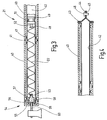
- einen Längsschnitt durch ein Ende der Wickelwelle und der Tragachse des Heckscheibenrollos nach Fig. 2 und
- Fig. 4
- einen Schnitt ähnlich dem nach Fig. 3 durch das andere Ende der Wickelwelle.
- Fig. 1
- a partially broken rear end of a motor vehicle, in a perspective view looking towards the inside of the rear window,
- Fig. 2
- the basic structure of the rear window roller blind of FIG. 1,
- Fig. 3
- a longitudinal section through one end of the winding shaft and the support shaft of the rear window roller blind of FIG. 2 and
- Fig. 4
- a section similar to that of FIG. 3 through the other end of the winding shaft.
Fig. 1 stellt den aufgebrochenen, abgeschnittenen Fondbereich eines PKW dar. Die Figur veranschaulicht einen Blick auf die rechte Innenseite, die zu der nicht veranschaulichten linken Innenseite spiegelbildlich ist. Die Darstellung ist vereinfacht. So sind beispielsweise Karosserieinnenstrukturen, wie Versteifung und Befestigungsmittel nicht gezeigt, da ihre Darstellung für das Verständnis der Erfindung nicht erforderlich ist. Ebenso ist die Darstellung der Karosserie schematisiert und lässt die dort vorhandenen Hohlräume nicht erkennen.Figure 1 illustrates the broken, cut-off rear region of a passenger car. The figure illustrates a view of the right inner side, which is a mirror image of the unillustrated left inner side. The presentation is simplified. For example, interior body structures, such as stiffening and fasteners are not shown because their representation for understanding the invention is not required. Similarly, the representation of the body is schematic and does not recognize the existing cavities there.
Der veranschaulichte Karosserieabschnitt 1 weist ein Dach 2 auf, von dem seitlich eine B-Säule 3 nach unten zu einer nicht gezeigten Bodengruppe führt. Eine entsprechende B-Säule wäre auf der weggebrochenen Seite des Fahrzeugs zu denken. Das Dach 2 geht an seiner Hinterkante in ein Heckfenster 4 über. Seitlich endet das Heckfenster an einer C-Säule 5, die sich im Abstand zu der B-Säule 3 befindet. Die C-Säule 5 trägt eine Innenverkleidung 6.The illustrated body section 1 has a
Zwischen der B-Säule 3 und der C-Säule 6 ist an der B-Säule 3 eine hintere, rechte Seitentür 7 in bekannter Weise anscharniert.Between the
Auf der Höhe der hinteren, rechten Seitentür 7 befindet sich eine Rücksatzbank 8, zu der eine Sitzfläche 9 sowie eine Rücksitzlehne 11 gehören. Die Rücksitzfläche 9 liegt auf einer Sockelfläche 12, die zu der Bodengruppe gehört und vor der Fußräume 13 ausgebildet sind.At the height of the rear, right side door 7 is a
Auf der Höhe der Oberkante der Rücksitzlehne 11 erstreckt sich eine Hutablage 15 zu der Unterkante der Heckscheibe 4.At the height of the upper edge of the rear seat back 11, a
Die hintere, rechte Seitentür ist in der für Limousinen üblichen Weise mit einem Seitenfenster 16 versehen.The rear, right side door is provided in the usual manner for sedans with a
Auf der Innenseite vor dem Heckfenster 4 befindet sich ein Heckscheibenrollo 16. Von dem Heckscheibenrollo 16 ist dessen teilweise ausgezogene Rollobahn 17 sowie eine der seitlichen Führungsschienen 18 zu erkennen. Die Führungsschiene 18 beginnt an der hinter der Rücksitzlehne 11 vorhandenen Hutablage 15 und verläuft neben der seitlichen Fensterkante. Außerdem enthält die Hutablage 15 einen durchgehendenden Auszugsschlitz 20, aus dem die Rollobahn 18 herausläuft. Der Auszugsschlitz 20 ist gekrümmt, um sich der Krümmung des Heckfensters 4 anzunähern.On the inside in front of the
Der prinzipelle Aufbau des Heckscheibenrollos 16 ergibt sich aus Fig. 2.The basic structure of the rear
Unterhalb der Hutablage 15 ist, wie sich aus Fig. 2 ergibt, eine gekrümmmte Wickelwelle 21 drehbar gelagert, an der mit einer Kante die Rollobahn 18 befestigt ist. Die Darstellung der Wickelwelle 21 ist in Fig. 2 stark schematisiert, die Einzelheiten ergeben sich aus den nachfolgenden Figuren.Below the
Die Wickelwelle 21 ist mit Hilfe eines schematisch angedeuteten Federmotors 22 im Sinne des Aufwickelns der Rollobahn 18 auf die Wickelwelle 21 vorgespannt. Hierzu ist eine Schraubenfeder vorgesehen, die einends karosseriefest verankert und andernends in der Wickelwelle 21 festgelegt ist.The winding
Die Krümmung der Wickelwelle 21 entspricht der Krümmung des Auszugschlitzes 20.The curvature of the winding
Die Rollobahn 17 weist einen etwa trapezförmigen Zuschnitt auf und ist an ihrer von der Wickelwelle 21 abliegenden Kante mit einer schlauchförmigen Schlaufe 23 versehen. Durch die schlauchförmige Schlaufe 23 führt ein Auszugsprofil oder Spriegel, in dem Endstücke 24 und 25 teleskopartig gelagert sind. Die Endstücke 24 und 25 weisen einen Halsteil 26 auf, der einen kleineren Durchmesser aufweist als ein sich daran anschließendes Führungsglied 27, das die Gestalt eines kurzen zylinderförmigen Abschnitts aufweist. Die Führungsglieder 27 laufen in den Führungsschienen 19, die neben den beiden Seitenkanten des Heckfensters 4 angeordnet sind.The
Da sowohl die Wickelwelle 21 als auch das Auszugsprofil in gleicher Weise gekrümmt sind, beschreibt die ausgezogene Rollobahn 18 eine gekrümmte Fläche, deren Erzeugende eine Gerade ist. Die Rollobahn 18 streift möglichst nicht an den Rändern des Auszugschlitzes 18.Since both the winding
Jede der Führungsschienen 19 enthält eine hinterschnittene Führungsnut 28, die sich in Richtung auf die Rollobahn 18 in einem Führungsschlitz öffnet.Each of the guide rails 19 includes an undercut
Das untere Ende jeder Führungsschiene 19 ist mit einem Führungsrohr 29, 30 verbunden, in denen ausknicksicher zwei biegsame Schubglieder 31 und 32 geführt sind. Die biegsamen Schubglieder 31 und 32 sind sogenannte SU-flexwellen. Sie bestehen aus einem zylinderförmigen Kern, der von einer schraubenförmig verlaufenden Rippe umgeben ist. Auf diese Weise wird eine Art flexibler Zahnstangen mit Rundumverzahnung erhalten.The lower end of each
Die Führungsrohre 29 und 30 verbinden die Führungsschienen 19 mit einem Getriebemotor 33. Der Getriebemotor 33 setzt sich aus einem permanent erregten Gleichstrommotor 34 und einem Getriebe 35 zusammen auf dessen Ausgangswelle 36 ein Stirnzahnrad 37 drehfest sitzt. Das Zahnrad 37 kämmt mit den beiden Schubgliedern 31, 32 formschlüssig. Die Schubglieder 31, 32 laufen tangential an die an diametral gegenüberliegenden Seiten an dem Stirnzahnrad 37 vorbei und sind hierzu in entsprechenden Bohrungen 38, 39 geführt.The
Durch Ingangsetzen des Getriebemotors 33 werden die Schubglieder 31, 32 wahlweise vorgeschoben oder zurückgezogen. Der Bewegung der Schubglieder 31, 32 folgen die Führungsstücke 24, 25. Diese werden mit Hilfe des Federmotors 22 gegen die freien Enden der Schubglieder 31, 32 anliegend gehalten, die sich in den Führungsnuten 28 befinden.By starting the geared
Der Aufbau der Wickelwelle wird nachstehend anhand der Figur 3 erläutert.The structure of the winding shaft will be explained below with reference to FIG.
Die Wickelwelle 21 setzt sich, wie die vergrößerte Darstellung erkennen lässt, aus mehreren in axialer Richtung nebeneinander liegenden rohrförmigen Wellenabschnitten 40 zusammen. Die rohrfömigen Wellenabschnitte 40 sind an den Stoßstellen bei 41 formschlüssig miteinander gekuppelt. Um die formschlüssige Kupplung zwischen den benachbarten Wellenabschnitten 40 herzustellen, weisen die Wellenabschnitte stirnseitig Laschen auf, zwischen denen Ausnehmungen oder Aussparungen enthalten sind, die die gleiche Gestalt wie die Laschen haben, derart, dass die Laschen an einer Seite in die Ausnehmungen auf der gegenüberliegenden Seite des anderen Wellenabschnittes 40 eingreifen können. Gleichzeitig ist diese formschlüssige Verbindung die Möglichkeit geben, dass die einzelnen Wellenabschnitte 40 gegeneinander kippen können, um so den gewünschten gekrümmten Verlauf der Wickelwelle 21 polygonartig anzunähern.The winding
Um der Wickelwelle 21 den gewünschten gekrümmten Verlauf aufzuprägen, sitzen die Wellenabschnitte 40 hintereinander auf einer rohrförmigen Achse 42. Die Achse 42 ist an einem Ende gemäß Fig. 4 in axialer Richtung gestaucht, wodurch ein radial nach außen stehender Flansch 43 entsteht, der als Widerlager für den unmittelbar benachbarten Wellenabschnitt 40 dient. Wie die Schnittdarstellung von Fig. 4 zeigt, ist das Wandmaterial, das die rohrförmige Achse 42 bildet im Bereich des Flansches 43 doppellagig.In order to impart the desired curved course to the winding
Zur rechten Seite hin ist der verbleibende an den Flansch 43 sich anschließende rohrförmige Teil flach gedrückt, wodurch eine ebene Befestigungsplatte entsteht, mit einer Öffnung 45 für ein Befestigungselement 46, beispielsweise eine Schraube, ein Niet oder dergleichen. Die Befestigungsplatte 44 ist durch die Umformung einstückiger Bestandteil der rohrfömigen Achse 42.Towards the right side, the remaining tubular part which adjoins the
Damit die rohrfömigen Abschnitte 40 auf der gekrümmten Achse 42 möglichst wenig Kippspiel haben, andererseits aber auch nicht klemmen, sind die rohrförmigen Wellenabschnitte 40 mit nach innen vorstehenden Warzen 47 versehen. Die Warzen 47 bilden jeweils Gruppen, wobei die Warzen innerhalb einer Gruppe auf einem zu der Achse des Wellenabschnitts 40 konzentrischen Kreis liegen. Jeweils eine Gruppe von diesen Warzen 47 ist in der Nähe des jeweiligen Stirnendes des Wellenabschnittes 40 vorgesehen, wie dies bei den vollständig gezeigten Wellenabschnitten 40 zu erkennen ist. Dadurch besteht die Möglichkeit, dass der rohrförmige Wellenabschnitt 40 im Bereich zwischen den Warzen 47 an den beiden Stirnenden hoch liegt und lediglich über die Warzen 47 mit der rohrförmigen Achse 42 in Berührung steht. Eine Krümmung der rohrförmigen Achse im Bereich zwischen den Enden der rohrförmigen Wellenabschnitte 40 führt nicht zum Klemmen.So that the
Die genaue Gestaltung der einzelnen rohrförmigen Abschnitte 40 kann der DE 103 38 900 A1 entnommen werden, auf die hier ausdrücklich Bezug genommen ist.The exact design of the individual
Der schematisch angedeutete Federmotor 22 besteht aus einer Schraubenfeder. Die Schraubenfeder 22 ist mit ihrem Ende 48 in einem Widerlager 49 verankert, der in der rohrförmigen Achse 42 steckt. Er ist dort mit Hilfe einer Sicke 51 verpresst, so dass er sich weder in axialer Richtung bewegen kann noch drehen kann. Im Bereich der Sicke 51 ist das Federwiderlager 49 mit einer entsprechenden Einschnürung versehen. Das Federwiderlager 49 trägt in Richtung auf die Feder 22 einen kurzen Zapfen 52 mit Querloch, in dem das Federende 48 eingehängt ist.The schematically indicated
Das andere Federende 53 ist mit einer becherförmigen Kappe 54 gekuppelt. Die becherförmige Kappe 54 setzt sich aus einem Boden 55 und einem daran anschließenden kurzen Kragen 56 zusammen. Der Kragen 56 ist an seinem freien Stirnende mit derselben Kupplungsverzahnung versehen, wie der benachbarte Wellenabschnitt 40, damit eine formschlüssige Kupplung zwischen der becherförmigen Kappe 54 und dem benachbarten Wellenabschnitt 40 besteht.The
Der Boden 55 trägt auf seiner der rohrförmigen Achse 42 benachbarten Seite eine zapfenförmige Verlängerung 57, in die das Federende 53 eingehängt ist.The bottom 55 carries on its side adjacent to the tubular axis 42 a pin-shaped
Auf der zapfenförmigen Verlängerung 57 sitzt noch eine Lagerbüchse 58, die dafür sorgt, dass die becherförmige Kappe 54 mit wenig Spiel drehbar in der rohrförmigen Achse 42 gelagert ist.On the pin-shaped
An der Außenseite ist der Boden 55 mit einer Sackbohrung 59 versehen, in die ein Lagerzapfen 60 hineinragt, der in der Karosserie fest verankert ist.On the outside of the bottom 55 is provided with a
Aufgrund der Anordnung der Schraubenfeder 22 wird die Wickelwelle 21 im Sinne eines Aufwickelns der Rollobahn 18 vorgespannt. Um das Drehmoment zu erzeugen, stützt sich die Schraubenfeder 22 über das feststehende Federwiderlager 49 in der Karosserie über die dort fest gehalterte rohrförmigen Achse 52 ab. Das andere Ende der Schraubenfeder 22 ist drehfest über die becherförmige Kappe 54 mit dem benachbarten rohrförmigen Wellenabschnitt 40 gekuppelt, der wiederum spielfrei oder spielarm mit dem ihm benachbarten Wellenabschnitt 40 verbunden ist. Auf diese Weise wird das von der Schraubenfeder 22 erzeugte Drehmoment auf sämtliche Wellenabschnitte 40 übertragen.Due to the arrangement of the
Die Schraubenfeder 22 ist nicht nur im rotatorischen Sinne an dem Federwiderlager 49 und der becherförmigen Kappe 54 verankert, sondern auch in axialer Richtung festgelegt. Durch entsprechende Lage des Federwiderlagers 49 kann somit sichergestellt werden, dass die Schraubenfeder 22 nicht nur das Antriebsdrehmoment erzeugt, sondern auch eine Zugkraft auf die becherförmige Kappe 54 ausübt, um die Abfolge der rohrförmigen Wellenabschnitte 40 stirnseitig gegeneinander zu drücken. Die Reaktionskraft wird schließlich von dem Flansch 43 aufgenommen.The
Da die Kappe über den Zapfen 57 und die Lagerbüchse 48 spielarm in der rohrförmigen Achse 42 gelagert ist und andererseits der ortsfeste Lagerzapfen 60 in die Sackbohrung 59 spielarm eingreift, ist auch das an sich frei auskragnede Ende der rohrförmigen Achse 40, das nicht unmittelbar mit der Karosserie verschraubt ist, in radiale Richtung geführt. Sämtliche Radialkräfte, die von der Wickelwelle 21 auf die rohrförmige Achse 40 übertragen werden, werden an einem Ende über die Platte 44 unmittelbar und an dem anderen Ende vermittels der drehbar gelagerten becherförmigen Kappe 54 in die Karosserie eingeleitet.Since the cap is mounted on the
Wie die Figuren erkennen lassen, führt durch die Schraubenfeder keine Stange oder dergleichen hindurch. Vielmehr kann die Schraubenfeder 22 ungehindert dem gekrümmten Verlauf der an sich gekrümmten rohrfömigen Achse 42,folgen. Diese Achse ist lediglich aus Gründen der Vereinfachung der Darstellung gestreckt gezeigt, folgt jedoch tatsächlich einem mehr oder weniger stark gekrümmten Verlauf. Durch die Krümmung der rohrförmigen Achse wird zwangsläufig sicher gestellt, dass sich die Schraubenfeder 22 an der Innenwand der rohrförmigen Achse 40 anliegt. Erschütterungen des Fahrzeugs können die Feder 22 nicht mehr zu Schwingungen anregen, die sie innerhalb der rohrförmigen Achse 42 klappern lassen könnten.As the figures show, no rod or the like passes through the coil spring. Rather, the
Bei einem Rollo mit gekrümmter Wickelwelle wird ein Federmotor verwendet, bei dem ein Federwiderlager innerhalb und an der Achse festgelegt ist, auf der die einzelnen Segmente der Wickelwelle drehbar gelagert sind. Dadurch wird eine Montageerleichterung geschaffen und die Feder wird in die Lage versetzt, sich an der Wand der Achse anzulegen, um Klappergeräusche zu vermeiden.In a roller blind with a curved winding shaft, a spring motor is used in which a spring abutment is fixed within and on the axis on which the individual segments of the winding shaft are rotatably mounted. As a result, a mounting relief is created and the spring is able to apply to the wall of the axle to avoid rattling noises.
Claims (10)
mit einer starren Achse (42), die bogenförmig gekrümmt, lediglich einends undrehbar gehaltert und, zumindest an dem freien Ende, rohrförmig ist,
mit einer auf der Achse (42) drehbar gelagerten Rollowelle (21), die aus wenigstens einem rohrförmigen Wellenabschnitt (40), dessen Innendurchmesser größer als der Außendurchmesser der Achse (42) ist, und einer Kappe (54) zusammengesetzt ist,
mit ortsfesten Lagermitteln (60) für die Kappe (54), die dazu eingerichtet sind die Kappe (54) drehbar zu lagern, wodurch das andere Ende der starren Achse 42() abgestützt ist
mit Kupplungsmitteln (41), die dazu eingerichtet sind, den Wellenabschnitte (40) drehfest mit der Kappe (54) zu kuppeln,
mit einer Rollobahn (18), die mit einer Kante an der Rollowelle (21) befestigt ist und die eine von der Rollowelle (19) abliegende Kante (22) aufweist, und
mit einem Federmotor (22), der in der Achse (42) untergebracht ist, dessen verankertes Ende in der Achse (42) liegt und dort festgesetzt ist und dessen anderes Ende mit der Kappe (54) drehfest verbunden ist.Window blind (17) for motor vehicles,
with a rigid axle (42) curved in an arc shape, supported only at one end in a non-rotatable manner, and tubular, at least at the free end,
a roller shaft (21) rotatably mounted on the axle (42) and composed of at least one tubular shaft portion (40) whose inside diameter is larger than the outside diameter of the axle (42) and a cap (54);
fixed bearing means (60) for the cap (54) adapted to rotatably support the cap (54), whereby the other end of the rigid axle 42 (14) is supported
coupling means (41) adapted to non-rotatably couple the shaft portions (40) to the cap (54);
with a roller blind (18) which is fixed with one edge to the roller blind shaft (21) and which has an edge (22) remote from the roller blind shaft (19), and
with a spring motor (22), which is housed in the axis (42) whose anchored end lies in the axis (42) and is fixed there and the other end with the cap (54) is rotatably connected.
Applications Claiming Priority (1)
| Application Number | Priority Date | Filing Date | Title |
|---|---|---|---|
| DE102004036948A DE102004036948B3 (en) | 2004-07-29 | 2004-07-29 | Curved window blind with internal spring abutment |
Publications (2)
| Publication Number | Publication Date |
|---|---|
| EP1621380A2 true EP1621380A2 (en) | 2006-02-01 |
| EP1621380A3 EP1621380A3 (en) | 2008-09-10 |
Family
ID=35229945
Family Applications (1)
| Application Number | Title | Priority Date | Filing Date |
|---|---|---|---|
| EP05014625A Withdrawn EP1621380A3 (en) | 2004-07-29 | 2005-07-06 | Curved roller blind with abutment for a spring |
Country Status (6)
| Country | Link |
|---|---|
| US (1) | US20060021721A1 (en) |
| EP (1) | EP1621380A3 (en) |
| JP (1) | JP4157882B2 (en) |
| KR (1) | KR100724303B1 (en) |
| CN (1) | CN1727632A (en) |
| DE (1) | DE102004036948B3 (en) |
Cited By (2)
| Publication number | Priority date | Publication date | Assignee | Title |
|---|---|---|---|---|
| EP1902879A2 (en) * | 2006-09-25 | 2008-03-26 | BOS GmbH & Co. KG | Roller blind assembly |
| EP2638230A4 (en) * | 2010-11-10 | 2015-08-05 | Markisol Holding Ab | Device for preloading a rewind mechanism |
Families Citing this family (4)
| Publication number | Priority date | Publication date | Assignee | Title |
|---|---|---|---|---|
| DE102010063450A1 (en) * | 2010-12-17 | 2012-06-21 | Bos Gmbh & Co. Kg | Roller blind system for a motor vehicle |
| DE102014209144A1 (en) * | 2013-06-28 | 2014-12-31 | Bos Gmbh & Co. Kg | Protective device for a vehicle interior |
| DE102015107573B3 (en) | 2015-05-13 | 2016-09-22 | Webasto SE | Arrangement for a winding system and winding system for a vehicle roof |
| DE102016203382B4 (en) * | 2016-03-02 | 2017-11-23 | Bos Gmbh & Co. Kg | Shading device for a vehicle interior |
Citations (1)
| Publication number | Priority date | Publication date | Assignee | Title |
|---|---|---|---|---|
| DE10338900A1 (en) | 2003-08-23 | 2005-03-17 | Bos Gmbh & Co. Kg | Curved window blind for motor vehicles |
Family Cites Families (15)
| Publication number | Priority date | Publication date | Assignee | Title |
|---|---|---|---|---|
| US516018A (en) * | 1894-03-06 | Shade-roller | ||
| US1071158A (en) * | 1913-04-26 | 1913-08-26 | Ishmael F Hurlbut | Curved shade-roller and curtain-rod. |
| DE1102581B (en) * | 1958-01-08 | 1961-03-16 | H T Golde G M B H & Co K G | Sun blind, especially for openings in the roofs of motor vehicles that can be closed with a sliding roof insert |
| US3092174A (en) * | 1959-02-06 | 1963-06-04 | Winn Stanley Pearson | Roller blind for curved windows and the like |
| US3069198A (en) * | 1960-04-11 | 1962-12-18 | Winn Stanley Pearson | Curved blinds for automobiles |
| JP3289223B2 (en) * | 1991-05-23 | 2002-06-04 | 日本発条株式会社 | Shielding device |
| US5127459A (en) * | 1991-08-12 | 1992-07-07 | Markowitz Steven L | Adjustable rod for tear-away adjustable window shades |
| FR2779475A1 (en) * | 1996-11-13 | 1999-12-10 | Farnier Et Penin Snc | Curved roller blind |
| NZ329574A (en) * | 1998-01-13 | 2000-06-23 | Formway Furniture Ltd | A height adjustable roller modesty screen for a table |
| DE19927384C1 (en) | 1999-06-16 | 2000-12-07 | Bos Gmbh | Separating device with variable retraction force |
| US6079474A (en) * | 1999-08-06 | 2000-06-27 | Lin; Yung-Ching | Sun-shade assembly |
| DE10005951A1 (en) * | 2000-02-09 | 2001-08-16 | Bos Gmbh | Rear window blind |
| NL1015212C1 (en) * | 2000-05-17 | 2000-06-19 | Inalfa Ind Bv | Open roof construction for a vehicle. |
| DE10046553A1 (en) * | 2000-09-19 | 2002-04-04 | Bos Gmbh | Window roller blind for curved or non-rectangular vehicle windows |
| DE10158428B4 (en) * | 2001-11-29 | 2005-09-22 | Webasto Ag | The blind assembly |
-
2004
- 2004-07-29 DE DE102004036948A patent/DE102004036948B3/en active Active
-
2005
- 2005-07-06 EP EP05014625A patent/EP1621380A3/en not_active Withdrawn
- 2005-07-28 KR KR1020050068702A patent/KR100724303B1/en not_active IP Right Cessation
- 2005-07-28 JP JP2005218318A patent/JP4157882B2/en not_active Expired - Fee Related
- 2005-07-28 US US11/191,703 patent/US20060021721A1/en not_active Abandoned
- 2005-07-28 CN CNA2005100879683A patent/CN1727632A/en active Pending
Patent Citations (1)
| Publication number | Priority date | Publication date | Assignee | Title |
|---|---|---|---|---|
| DE10338900A1 (en) | 2003-08-23 | 2005-03-17 | Bos Gmbh & Co. Kg | Curved window blind for motor vehicles |
Cited By (3)
| Publication number | Priority date | Publication date | Assignee | Title |
|---|---|---|---|---|
| EP1902879A2 (en) * | 2006-09-25 | 2008-03-26 | BOS GmbH & Co. KG | Roller blind assembly |
| EP1902879A3 (en) * | 2006-09-25 | 2009-03-25 | BOS GmbH & Co. KG | Roller blind assembly |
| EP2638230A4 (en) * | 2010-11-10 | 2015-08-05 | Markisol Holding Ab | Device for preloading a rewind mechanism |
Also Published As
| Publication number | Publication date |
|---|---|
| KR20060048835A (en) | 2006-05-18 |
| DE102004036948B3 (en) | 2006-03-23 |
| EP1621380A3 (en) | 2008-09-10 |
| JP2006036201A (en) | 2006-02-09 |
| US20060021721A1 (en) | 2006-02-02 |
| JP4157882B2 (en) | 2008-10-01 |
| CN1727632A (en) | 2006-02-01 |
| KR100724303B1 (en) | 2007-06-04 |
Similar Documents
| Publication | Publication Date | Title |
|---|---|---|
| EP1598517B1 (en) | Roller blind with coil spring motor | |
| EP1666291B1 (en) | Window roller blind with simplified assembly | |
| EP1859976B1 (en) | Roller blind with silent coil spring motor | |
| EP1375219B1 (en) | Roller blind for rear window with liftable storage box | |
| EP1724137B1 (en) | Window roller blind with axially adjustable winding shaft | |
| EP1894758B1 (en) | Side window roller blind | |
| EP2060421B1 (en) | Shutter arrangement with lower friction in the drive | |
| DE10339583B4 (en) | Plastic injection molded guide rail | |
| DE102007012281A1 (en) | Automatically operated side window blind | |
| EP1905625A1 (en) | Roller blind with undercut-free guide rail | |
| DE10005951A1 (en) | Rear window blind | |
| EP1736335A2 (en) | Roller blind for rear window with complete slot cover by the pull-out element | |
| EP1932700A2 (en) | Roller blind for triangular windows of motor vehicles | |
| EP1621380A2 (en) | Curved roller blind with abutment for a spring | |
| EP1510382B1 (en) | Curved roller blind for vehicles | |
| EP1707412A2 (en) | Roller blind for side window with slidable winding tube | |
| DE102007039255A1 (en) | Rear window roller blind with angular support rail | |
| EP1738942B1 (en) | Motor vehicle window blind with a stop rigidly fixed to the drive linkage | |
| DE102016208896B4 (en) | Shading device for a vehicle window | |
| EP2062767B1 (en) | Vehicle roller blind with tensioning spring and spring core | |
| DE202005020696U1 (en) | Window roller blind for motor vehicles has spring motor coupled to winding shaft and pretensions it in sense of winding-on of roller blind web onto winding shaft, and guide rail is inserted into one end of extension profile | |
| EP1520740A2 (en) | Roller blind with two-part pull-out element | |
| DE102018204253A1 (en) | Spindle drive and method for its production | |
| DE202005020609U1 (en) | Window shade for motor vehicle has roller blind web, roller shaft, actuation device, and storage arrangement wherein storage arrangement has adjustment unit by which axial position of roller shaft is adjustable | |
| DE202007015809U1 (en) | Rear window roller blind with angular support rail |
Legal Events
| Date | Code | Title | Description |
|---|---|---|---|
| PUAI | Public reference made under article 153(3) epc to a published international application that has entered the european phase |
Free format text: ORIGINAL CODE: 0009012 |
|
| AK | Designated contracting states |
Kind code of ref document: A2 Designated state(s): AT BE BG CH CY CZ DE DK EE ES FI FR GB GR HU IE IS IT LI LT LU LV MC NL PL PT RO SE SI SK TR |
|
| AX | Request for extension of the european patent |
Extension state: AL BA HR MK YU |
|
| PUAL | Search report despatched |
Free format text: ORIGINAL CODE: 0009013 |
|
| AK | Designated contracting states |
Kind code of ref document: A3 Designated state(s): AT BE BG CH CY CZ DE DK EE ES FI FR GB GR HU IE IS IT LI LT LU LV MC NL PL PT RO SE SI SK TR |
|
| AX | Request for extension of the european patent |
Extension state: AL BA HR MK YU |
|
| 17P | Request for examination filed |
Effective date: 20090304 |
|
| STAA | Information on the status of an ep patent application or granted ep patent |
Free format text: STATUS: THE APPLICATION HAS BEEN WITHDRAWN |
|
| AKX | Designation fees paid |
Designated state(s): DE FR GB |
|
| 18W | Application withdrawn |
Effective date: 20090418 |