EP1621111A1 - Sitz für öffentliche Verkehrsmittel - Google Patents
Sitz für öffentliche Verkehrsmittel Download PDFInfo
- Publication number
- EP1621111A1 EP1621111A1 EP05291586A EP05291586A EP1621111A1 EP 1621111 A1 EP1621111 A1 EP 1621111A1 EP 05291586 A EP05291586 A EP 05291586A EP 05291586 A EP05291586 A EP 05291586A EP 1621111 A1 EP1621111 A1 EP 1621111A1
- Authority
- EP
- European Patent Office
- Prior art keywords
- seat
- slot
- coating
- covered
- edge
- Prior art date
- Legal status (The legal status is an assumption and is not a legal conclusion. Google has not performed a legal analysis and makes no representation as to the accuracy of the status listed.)
- Withdrawn
Links
- 230000002093 peripheral effect Effects 0.000 claims abstract description 35
- 208000034693 Laceration Diseases 0.000 claims abstract description 10
- 239000004744 fabric Substances 0.000 claims abstract description 5
- 239000011248 coating agent Substances 0.000 claims description 51
- 238000000576 coating method Methods 0.000 claims description 51
- 238000004026 adhesive bonding Methods 0.000 claims description 10
- 239000000463 material Substances 0.000 claims description 8
- 230000001413 cellular effect Effects 0.000 claims description 3
- 239000002991 molded plastic Substances 0.000 claims description 2
- 238000000465 moulding Methods 0.000 claims description 2
- 238000004519 manufacturing process Methods 0.000 description 2
- 239000002184 metal Substances 0.000 description 2
- 239000004033 plastic Substances 0.000 description 2
- 230000002787 reinforcement Effects 0.000 description 2
- 238000005520 cutting process Methods 0.000 description 1
- 238000007373 indentation Methods 0.000 description 1
- 238000002347 injection Methods 0.000 description 1
- 239000007924 injection Substances 0.000 description 1
- 238000000034 method Methods 0.000 description 1
- 239000000243 solution Substances 0.000 description 1
- 229920002994 synthetic fiber Polymers 0.000 description 1
Images


Classifications
-
- A—HUMAN NECESSITIES
- A47—FURNITURE; DOMESTIC ARTICLES OR APPLIANCES; COFFEE MILLS; SPICE MILLS; SUCTION CLEANERS IN GENERAL
- A47C—CHAIRS; SOFAS; BEDS
- A47C7/00—Parts, details, or accessories of chairs or stools
- A47C7/02—Seat parts
- A47C7/24—Upholstered seats
- A47C7/26—Upholstered seats with reinforcement of the external layer of the upholstery, e.g. vandal resistant
-
- B—PERFORMING OPERATIONS; TRANSPORTING
- B60—VEHICLES IN GENERAL
- B60N—SEATS SPECIALLY ADAPTED FOR VEHICLES; VEHICLE PASSENGER ACCOMMODATION NOT OTHERWISE PROVIDED FOR
- B60N2/00—Seats specially adapted for vehicles; Arrangement or mounting of seats in vehicles
- B60N2/24—Seats specially adapted for vehicles; Arrangement or mounting of seats in vehicles for particular purposes or particular vehicles
- B60N2/242—Bus seats
-
- B—PERFORMING OPERATIONS; TRANSPORTING
- B60—VEHICLES IN GENERAL
- B60N—SEATS SPECIALLY ADAPTED FOR VEHICLES; VEHICLE PASSENGER ACCOMMODATION NOT OTHERWISE PROVIDED FOR
- B60N2/00—Seats specially adapted for vehicles; Arrangement or mounting of seats in vehicles
- B60N2/70—Upholstery springs ; Upholstery
Definitions
- the present invention relates to a seat, particularly for a public transport vehicle, of the type comprising a seat, a backrest, and a coating placed on at least a portion of the seat and / or backrest.
- a seat of this type must meet several requirements such as robustness sufficiently important for use as long as possible, comfort that may vary according to the type of vehicles equipped with these seats and the average duration of trips made in these vehicles, and a simple realization so as to reduce production costs.
- the seat and the backrest of the seat are made of plastic material.
- a coating optionally associated with a lining and a laceration or anti-vandalism web is placed and fixed on the seat and / or the seat back.
- the present invention is essentially intended to provide a simple, effective and economical solution to this problem.
- a seat in particular for a public transport vehicle, comprising a seat, a backrest and a covering covering at least part of the seat and / or backrest, characterized in that the said covered part is delimited. by a continuous slot which extends over at least a part of the periphery of this covered part and in which is inserted and fixed a peripheral edge of the coating, and in that the covered part is connected to a peripheral portion not covered with the 'seat or backrest by ribs which extend transversely to the slot and which are formed on the face lower or inner side of the backrest or seat.
- the continuous slot which delimits the portion covered with the seat according to the invention makes it possible to introduce part or all of the peripheral edge of the coating.
- the peripheral edge of the coating is no longer visible and accessible, which reduces its wear and improve the aesthetics of the seat.
- Fixing the seat cover according to the invention is simple and inexpensive. It can be achieved by gluing the coating on the part to be covered and in the slot of the seat. Staples may also be used to secure the peripheral edge of the liner to a wall of this slot.
- transverse ribs make it possible to connect the peripheral part not covered with the backrest or the seat to the covered part and to strengthen the backrest or the seat.
- the continuous slot forms in the aforementioned ribs notches whose depth allows the reception of the peripheral edge of the coating.
- the connecting ribs and reinforcement do not interfere with the introduction and attachment of the peripheral edge of the coating in the slot of the backrest or seat.
- the coated portion is for example of plastic material, which comprises molding the slot and the aforementioned ribs.
- the slot has a substantially U-shaped shape and extends along the front edge and the side edges and up to the rear edge of the seat or backrest, respectively.
- a lining for example made of cellular material, is interposed between the coating and the part to be covered, the lining being able to be fixed on the part to be covered, for example by gluing or the like.
- an anti-vandalism or anti-laceration tablecloth may be interposed between the coating and the lining and for example fixed on the lining, by gluing or similar.
- the slot then comprises two superimposed portions having different widths, the widest part opening on the part covered and extending along the peripheral edge of the covered part.
- the seat according to the invention has the advantage of offering several levels of comfort from a seat and a standard backrest, these comfort levels being adapted to vehicles of different types, including public transport vehicles.
- the seat cover according to the invention it is easy to replace or renovate the seat cover according to the invention, either by removing the worn coating and placing a new coating in its place, either by retaining the worn coating and overlaying a new coating.
- the peripheral edge of the new coating introduced and fixed in the slot of the file or seat covers that of the worn coating, unless it has been previously cut and removed from the slot.
- the invention also proposes a tool for mounting a coating on a seat of the type described above, characterized in that it comprises a thin annular wall in the shape of the slot of the seat part to be covered, this wall being carried by a vertically sliding guided mobile support above a fixed support carrying said seat part, so that when the covering is placed on the seat part, the vertical sliding down of the movable support is embedded the edge of the coating, by means of said thin annular wall, in the slot of the part of the seat.
- a seat according to the invention in particular for a public transport vehicle, comprises a seat designated by the reference 10 in FIG. 2 and a folder designated by the reference 110 in FIG. 1, which are fixedly mounted on a support structure, not shown. which is itself fixed for example to a support leg and to the fixing means to a vertical wall.
- the seat 10, shown in Figures 2 to 5, is formed of a single piece of injection molded plastic material. It comprises a central portion 12 having a top surface covered with a coating of type fabric or the like which is fixed thereon for example by gluing and a vertical rear flange 18 extending downwardly from this upper surface, and a peripheral portion 14 U, surrounding the central portion 12 and having a top surface
- the U-shaped portion 14 includes a front edge 20 and two side edges 22 extending to the rear edge 24 of the seat 10.
- the seat 10 is reinforced by ribs 26, 28, for example transverse and longitudinal, which are formed on its underside or inside, as can be seen in FIGS. 3 and 4.
- the central portion 12 of the seat 10 is delimited by a continuous substantially U-shaped slot 30 which separates it from the peripheral portion 14 and which extends along the front edge 20 and the lateral edges 22 of the portion 14, until at the rear edge 24 of the seat 10.
- This slot 30 opens inside the seat 10 and is delimited internally by the edge 32 of the central portion 12 and externally by a vertical flange 34 of the peripheral portion 14.
- transverse and longitudinal ribs 26, 28 are traversed by the slot 30 which forms notches 36 whose dimensions are substantially equal to those of the cross section of the slot 30.
- Some ribs include, as shown in Figure 4, U-shaped indentations 37 opening downwardly for receiving metal tubes or the like forming part of the seat support structure.
- the slot 30 is intended to receive at least a portion of the peripheral edge of the stretched coating, arranged and fixed on the central portion 12 of the seat 10.
- the covering 38 is a sheet of flexible material such as fabric or fabric for example, having the shape of the central part 12 to be covered and slightly larger dimensions so that its front edges and lateral 40 can are introduced and fixed in the slot 30, its rear edge being folded down and fixed on the rear flange 18 of the central portion 12 of the seat 10.
- the central portion of the coating 38 is fixed on the portion 12 of the seat 10 by gluing or the like.
- the front edge and the lateral edges 40 of the coating 38 are introduced into the slot 30 and fixed on the radially outer wall of the slot 30, formed by the vertical flange 34 of the peripheral portion 14, by gluing and / or by means of staples 42 or the like.
- the staples 42 are placed by means of a suitable tool which is manipulated on the side of the inner or lower face of the seat 10.
- a suitable tool which is manipulated on the side of the inner or lower face of the seat 10.
- the absence of a radially inner wall of the slot 30 makes it possible to place the tool as close to the portion 12 of the seat 10 for fixing the edge 40 of the coating 38 on the radially outer wall of the slot 30.
- the notches 36 formed in the transverse and longitudinal ribs 26, 28 ensure the continuity of the slot 30 and also receive the front and side edges 40 of the coating 38.
- the peripheral edge 40 of the coating 38 which is introduced into the slot 30, comes out of this slot downwards, under the seat 10, and makes it possible to exert traction on the covering 38 so as to stretch it onto the portion 12 of the seat 10.
- the portion of this edge which protrudes from the slot 30 downwards is removed by cutting.
- This embodiment of seat is for example for public transport vehicles making relatively short trips during which the comfort of the seat is not important.
- a lining 44 of natural or synthetic material is interposed between the coating 38 and the central portion 12 of the seat 10, as shown in FIG. 7 and can be glued on this part. 12.
- an anti-vandalism or anti-laceration ply 46 is interposed between the coating 38 and the This layer 46, which generally comprises a metal reinforcement, resists attempts to lacerate the coating 38 and the lining 44 of the seat 10 and thus makes it possible to increase its service life.
- This type of web is known to those skilled in the art and is described in EP-A-1 127 517 of the applicant.
- the lining 44 and the ply 46 have the shape of the central portion 12 to be covered and of substantially equal or slightly smaller dimensions so as not to impede the introduction of the peripheral edge 40 of the covering 38 into the slot 30 of the seat 10. They are respectively attached to the portion 12 of the seat 10 and the lining 44 by gluing or the like.
- the peripheral edge of the ply 46 may for example be fixed by staples 48 on the peripheral edge of the central portion 12 of the seat 10.
- the slot 30 is wide enough to receive the peripheral edges of the ply 46 and the coating 38.
- the dimensions of the web 46 are slightly greater than those of the portion 12 to be covered so that its front and side edges can be introduced and fixed in the slot 30, for example by stapling.
- the seat back 110 also has on its front face a central portion 112 covered with a cloth-like coating 138 or the like and a peripheral portion 114 in a U-shape, surrounding the central portion 112.
- This portion 112 is separated from the peripheral portion 114 by a continuous slot 130 extending along the upper edge 120 and the lateral edges 122 of the peripheral portion 114, to the lower edge 124 of the front face of the backrest 110.
- groove 130 is intended to receive at least a portion of the peripheral edge of the coating 138 stretched, arranged and fixed on the portion 112 of the front face of the backrest 110, as already described with respect to the seat of the seat.
- Figure 10 illustrates a tool for mounting a coating on a seat back 110 according to the invention.
- the tool 200 comprises a thin annular wall 202 in the shape of the slot 130 which delimits the central portion 112 of the file 110 which must be covered with a coating.
- the backrest 110 is mounted on a fixed support not shown and the thin wall 202 is carried by a plate 204 which is mounted and guided in vertical sliding above the portion 112 of the backrest 110, on four fixed uprights 206 arranged at the corners of the plate 204.
- the peripheral edge of the sheet may be introduced into the slot 130 by means of this tool and fixed, then the peripheral edge 140 of the coating 138 is introduced into the slot 130 by means of the tool and fixed by gluing.
- the vertical sliding of the plate 204 downwards is embedded in the peripheral edge of the coating in the slot 130 of the backrest 110 by means of the thin annular wall 202.
- This tool is of course usable for a seat part delimited by a continuous slot.
- the slot formed around the central portion of the seat or backrest may be constituted by a closed bottom groove into which is introduced and fixed, for example by gluing, the edge of the coating of the central portion.
- the bottom of the groove and possibly one of its side walls are interrupted to allow the fixing of the edge of the coating by stitching as shown in Figures 6, 7 and 8.
Abstract
Description
La présente invention concerne un siège, en particulier pour véhicule de transport en commun, du type comprenant une assise, un dossier, et un revêtement posé sur au moins une partie de l'assise et/ou du dossier.The present invention relates to a seat, particularly for a public transport vehicle, of the type comprising a seat, a backrest, and a coating placed on at least a portion of the seat and / or backrest.
Un siège de ce type doit répondre à plusieurs exigences telles qu'une robustesse suffisamment importante pour une utilisation aussi longue que possible, un confort qui peut varier suivant le type des véhicules équipés de ces sièges et la durée moyenne des voyages effectués dans ces véhicules, et une réalisation simple de manière à réduire les coûts de production.A seat of this type must meet several requirements such as robustness sufficiently important for use as long as possible, comfort that may vary according to the type of vehicles equipped with these seats and the average duration of trips made in these vehicles, and a simple realization so as to reduce production costs.
Dans une version simple et peu coûteuse de ce siège, destinée en particulier aux autobus et à certains véhicules ferroviaires, l'assise et le dossier du siège sont réalisés en matériau plastique. Pour améliorer le confort et l'aspect du siège, un revêtement éventuellement associé à un garnissage et à une nappe anti-lacération ou anti-vandalisme est posé et fixé sur l'assise et/ou le dossier du siège.In a simple and inexpensive version of this seat, intended in particular for buses and certain railway vehicles, the seat and the backrest of the seat are made of plastic material. To improve the comfort and appearance of the seat, a coating optionally associated with a lining and a laceration or anti-vandalism web is placed and fixed on the seat and / or the seat back.
La pose et la fixation de ce revêtement par des techniques traditionnelles sont longues et coûteuses et augmentent le prix de revient du siègeThe laying and fixing of this coating by traditional techniques are long and expensive and increase the cost of the seat
La présente invention a essentiellement pour but d'apporter une solution simple, efficace et économique à ce problème.The present invention is essentially intended to provide a simple, effective and economical solution to this problem.
Elle propose à cet effet un siège, en particulier pour véhicule de transport en commun, comprenant une assise, un dossier et un revêtement recouvrant au moins une partie de l'assise et/ou du dossier, caractérisé en ce que ladite partie recouverte est délimitée par une fente continue qui s'étend sur au moins une partie de la périphérie de cette partie recouverte et dans laquelle est introduit et fixé un bord périphérique du revêtement, et en ce que la partie recouverte est raccordée à une partie périphérique non recouverte de l'assise ou du dossier par des nervures qui s'étendent transversalement par rapport à la fente et qui sont formées sur la face inférieure ou face interne du dossier ou de l'assise.To this end, it proposes a seat, in particular for a public transport vehicle, comprising a seat, a backrest and a covering covering at least part of the seat and / or backrest, characterized in that the said covered part is delimited. by a continuous slot which extends over at least a part of the periphery of this covered part and in which is inserted and fixed a peripheral edge of the coating, and in that the covered part is connected to a peripheral portion not covered with the 'seat or backrest by ribs which extend transversely to the slot and which are formed on the face lower or inner side of the backrest or seat.
La fente continue qui délimite la partie recouverte du siège selon l'invention permet d'y introduire une partie ou la totalité du bord périphérique du revêtement. Ainsi, le bord périphérique du revêtement n'est plus visible et accessible, ce qui permet de diminuer son usure et d'améliorer l'esthétique du siège.The continuous slot which delimits the portion covered with the seat according to the invention makes it possible to introduce part or all of the peripheral edge of the coating. Thus, the peripheral edge of the coating is no longer visible and accessible, which reduces its wear and improve the aesthetics of the seat.
La fixation du revêtement du siège selon l'invention est simple et peu coûteuse. Elle peut être réalisée par collage du revêtement sur la partie à recouvrir et dans la fente du siège. Des agrafes peuvent également être utilisées pour fixer le bord périphérique du revêtement sur une paroi de cette fente.Fixing the seat cover according to the invention is simple and inexpensive. It can be achieved by gluing the coating on the part to be covered and in the slot of the seat. Staples may also be used to secure the peripheral edge of the liner to a wall of this slot.
Les nervures transversales permettent de raccorder la partie périphérique non recouverte du dossier ou de l'assise à la partie recouverte et de renforcer le dossier ou l'assise.The transverse ribs make it possible to connect the peripheral part not covered with the backrest or the seat to the covered part and to strengthen the backrest or the seat.
La fente continue forme dans les nervures précitées des encoches dont la profondeur permet la réception du bord périphérique du revêtement. Ainsi les nervures de raccord et de renfort ne gênent pas l'introduction et la fixation du bord périphérique du revêtement dans la fente du dossier ou de l'assise.The continuous slot forms in the aforementioned ribs notches whose depth allows the reception of the peripheral edge of the coating. Thus the connecting ribs and reinforcement do not interfere with the introduction and attachment of the peripheral edge of the coating in the slot of the backrest or seat.
La partie recouverte est par exemple en matériau plastique, qui comporte de moulage la fente et les nervures précitées.The coated portion is for example of plastic material, which comprises molding the slot and the aforementioned ribs.
Dans un mode de réalisation préféré de l'invention, la fente a une forme sensiblement en U et s'étend le long du bord avant et des bords latéraux et jusqu'au bord arrière de l'assise ou du dossier, respectivement.In a preferred embodiment of the invention, the slot has a substantially U-shaped shape and extends along the front edge and the side edges and up to the rear edge of the seat or backrest, respectively.
Pour un bon confort, un garnissage, par exemple en matériau cellulaire, est interposé entre le revêtement et la partie à recouvrir, le garnissage pouvant être fixé sur la partie à recouvrir par exemple par collage ou analogue.For a good comfort, a lining, for example made of cellular material, is interposed between the coating and the part to be covered, the lining being able to be fixed on the part to be covered, for example by gluing or the like.
Afin d'augmenter la durée de vie du siège, une nappe anti-vandalisme ou anti-lacération peut-être interposée entre le revêtement et le garnissage et par exemple fixée sur le garnissage, par collage ou analogue.In order to increase the life of the seat, an anti-vandalism or anti-laceration tablecloth may be interposed between the coating and the lining and for example fixed on the lining, by gluing or similar.
Avantageusement, la fente comporte alors deux parties superposées ayant des largeurs différentes, la partie la plus large débouchant sur la partie recouverte et s'étendant le long du bord périphérique de la partie recouverte.Advantageously, the slot then comprises two superimposed portions having different widths, the widest part opening on the part covered and extending along the peripheral edge of the covered part.
Cela permet de fixer le bord de la nappe anti-vandalisme ou anti-lacération dans la fente, par collage ou agrafage par exemple, sur la paroi radialement interne de la partie la plus large de la fente, puis d'introduire et de fixer le bord du revêtement dans la partie la moins large de la fente en recouvrant ainsi le bord de la nappe anti-vandalisme ou anti-lacération.This makes it possible to fix the edge of the anti-vandalism or anti-laceration sheet in the slot, by bonding or stapling, for example, on the radially inner wall of the widest part of the slot, and then to introduce and fix the edge of the coating in the narrowest part of the slot thus covering the edge of the anti-vandal or anti-laceration sheet.
Le siège selon l'invention présente l'avantage d'offrir plusieurs niveaux de confort à partir d'une assise et d'un dossier standard, ces niveaux de confort étant adaptés à des véhicules de types différents, notamment des véhicules de transport public.The seat according to the invention has the advantage of offering several levels of comfort from a seat and a standard backrest, these comfort levels being adapted to vehicles of different types, including public transport vehicles.
De plus, il est facile de remplacer ou rénover le revêtement du siège selon l'invention, soit en enlevant le revêtement usé et en posant un revêtement neuf à sa place, soit en conservant le revêtement usé et en posant par dessus un revêtement neuf. Dans ce dernier cas, le bord périphérique du revêtement neuf introduit et fixé dans la fente du dossier ou de l'assise recouvre celui du revêtement usé, à moins que celui-ci n'ait été préalablement découpé et enlevé de la fente.In addition, it is easy to replace or renovate the seat cover according to the invention, either by removing the worn coating and placing a new coating in its place, either by retaining the worn coating and overlaying a new coating. In the latter case, the peripheral edge of the new coating introduced and fixed in the slot of the file or seat covers that of the worn coating, unless it has been previously cut and removed from the slot.
L'invention propose également un outil de montage d'un revêtement sur un siège du type décrit ci-dessus, caractérisé en ce qu'il comprend une paroi annulaire mince à la forme de la fente de la partie de siège à recouvrir, cette paroi étant portée par un support mobile guidé à coulissement vertical au-dessus d'un support fixe portant ladite partie de siège, de sorte que, quand le revêtement est placé sur la partie de siège, le coulissement vertical vers le bas du support mobile vient encastrer le bord du revêtement, au moyen de ladite paroi annulaire mince, dans la fente de la partie du siège.The invention also proposes a tool for mounting a coating on a seat of the type described above, characterized in that it comprises a thin annular wall in the shape of the slot of the seat part to be covered, this wall being carried by a vertically sliding guided mobile support above a fixed support carrying said seat part, so that when the covering is placed on the seat part, the vertical sliding down of the movable support is embedded the edge of the coating, by means of said thin annular wall, in the slot of the part of the seat.
L'invention sera mieux comprise et d'autres détails, avantages et caractéristiques de l'invention apparaîtront à la lecture de la description suivante faite à titre d'exemple non limitatif en référence aux dessins annexés, dans lesquels :
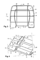
- les figures 1 et 2 sont des vues schématiques en perspective du dossier et de l'assise, respectivement, d'un siège pour véhicule de transport en commun selon l'invention ;
- la figure 3 est une vue schématique de dessous de l'assise de la figure 2 ;
- la figure 4 est une vue schématique partielle en perspective du dessous de l'assise de la figure 2 ;
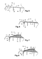
- la figure 5 est une vue schématique partielle en coupe transversale de l'assise du siège selon l'invention ;
- la figure 6 est une vue correspondant à la figure 5 et représente un revêtement posé sur l'assise ;
- la figure 7 est une vue correspondant à la figure 5 et représente un revêtement et une garniture élastique posés sur l'assise ;
- la figure 8 est une vue correspondant à la figure 5 et représente un revêtement, une garniture élastique et une nappe anti-vandalisme ou anti-lacération posés sur l'assise ;
- la figure 9 est une vue correspondant à la figure 8 et représente une variante de réalisation ; et
- la figure 10 est une vue schématique en perspective d'un outil de montage d'un revêtement sur un dossier de siège selon l'invention.
- Figures 1 and 2 are schematic perspective views of the backrest and the seat, respectively, of a seat for a public transport vehicle according to the invention;
- Figure 3 is a schematic bottom view of the seat of Figure 2;
- Figure 4 is a partial schematic perspective view of the underside of the seat of Figure 2;
- Figure 5 is a partial schematic view in cross section of the seat of the seat according to the invention;
- Figure 6 is a view corresponding to Figure 5 and shows a coating on the seat;
- Figure 7 is a view corresponding to Figure 5 and shows a coating and an elastic seal placed on the seat;
- Figure 8 is a view corresponding to Figure 5 and shows a coating, an elastic lining and a vandal-proof or anti-laceration layer placed on the seat;
- Figure 9 is a view corresponding to Figure 8 and shows an alternative embodiment; and
- Figure 10 is a schematic perspective view of a mounting tool of a coating on a seat back according to the invention.
Un siège selon l'invention, en particulier pour véhicule de transport en commun, comprend une assise désignée par la référence 10 en figure 2 et un dossier désigné par la référence 110 en figure 1, qui sont montés fixement sur une structure de support non représentée qui est elle-même fixée par exemple à un piètement d'appui au sol et à des moyens de fixation à une paroi verticale.A seat according to the invention, in particular for a public transport vehicle, comprises a seat designated by the
L'assise 10, représentée aux figures 2 à 5, est formée d'une seule pièce en matériau plastique moulé par injection. Elle comporte une partie centrale 12 ayant une surface supérieure recouverte d'un revêtement du type tissu ou analogue qui est fixé sur celle-ci par exemple par collage et un rebord arrière vertical 18 s'étendant vers le bas depuis cette surface supérieure, et une partie périphérique 14 en U, entourant la partie centrale 12 et ayant une surface supérieure 16 légèrement concave et un rebord périphérique vertical s'étendant vers le bas depuis la surface supérieure 16. La partie 14 en U comprend un bord avant 20 et deux bords latéraux 22 s'étendant jusqu'au bord arrière 24 de l'assise 10.The
L'assise 10 est renforcée par des nervures 26, 28, par exemple transversales et longitudinales, qui sont formées sur sa face inférieure ou interne, comme cela est visible en figures 3 et 4.The
La partie centrale 12 de l'assise 10 est délimitée par une fente continue 30 sensiblement en U qui la sépare de la partie périphérique 14 et qui s'étend le long du bord avant 20 et des bords latéraux 22 de la partie 14, jusqu'au bord arrière 24 de l'assise 10.The
Cette fente 30 débouche à l'intérieur de l'assise 10 et est délimitée intérieurement par le bord 32 de la partie centrale 12 et extérieurement par un rebord vertical 34 de la partie périphérique 14.This
Les nervures transversales et longitudinales 26, 28 sont traversées par la fente 30 qui y forme des encoches 36 dont les dimensions sont sensiblement égales à celles de la section transversale de la fente 30.The transverse and
Certaines nervures comprennent, comme représenté en figure 4, des échancrures 37 en U débouchant vers le bas et destinées à recevoir des tubes métalliques ou analogues faisant partie de la structure de support du siège.Some ribs include, as shown in Figure 4, U-shaped
La fente 30 est destinée à recevoir au moins une partie du bord périphérique du revêtement tendu, disposé et fixé sur la partie centrale 12 de l'assise 10.The
Dans le mode de réalisation illustré en figure 6, le revêtement 38 est une feuille de matière souple telle que de la toile ou du tissu par exemple, ayant la forme de la partie centrale 12 à recouvrir et des dimensions légèrement supérieures pour que ses bords avant et latéraux 40 puissent être introduits et fixés dans la fente 30, son bord arrière étant rabattu et fixé sur le rebord arrière 18 de la partie centrale 12 de l'assise 10.In the embodiment illustrated in FIG. 6, the
La partie centrale du revêtement 38 est fixée sur la partie 12 de l'assise 10 par collage ou analogue. Le bord avant et les bords latéraux 40 du revêtement 38 sont introduits dans la fente 30 et fixés sur la paroi radialement externe de la fente 30, formée par le rebord vertical 34 de la partie périphérique 14, par collage et/ou au moyen d'agrafes 42 ou analogues.The central portion of the
Les agrafes 42 sont posées au moyen d'un outil approprié qui est manipulé du côté de la face interne ou inférieure de l'assise 10. L'absence de paroi radialement interne de la fente 30 permet de placer l'outil au plus près de la partie 12 de l'assise 10 pour la fixation du bord 40 du revêtement 38 sur la paroi radialement externe de la fente 30.The
Les encoches 36 formées dans les nervures transversales et longitudinales 26, 28 assurent la continuité de la fente 30 et reçoivent également les bords avant et latéraux 40 du revêtement 38.The
Avantageusement, le bord périphérique 40 du revêtement 38, qui est introduit dans la fente 30, sort de cette fente vers le bas, sous l'assise 10, et permet d'exercer une traction sur le revêtement 38 de façon à bien le tendre sur la partie 12 de l'assise 10. Après fixation du bord périphérique 40 du revêtement 38 sur la paroi externe de la fente 30, la partie de ce bord qui dépasse de la fente 30 vers le bas, est éliminée par découpe.Advantageously, the
Cette réalisation de siège est par exemple destinée aux véhicules de transport en commun effectuant des trajets relativement courts pendant lesquels le confort du siège ne présente pas un caractère important.This embodiment of seat is for example for public transport vehicles making relatively short trips during which the comfort of the seat is not important.
Pour un meilleur confort, un garnissage 44 en matériau naturel ou synthétique, tel qu'un matériau cellulaire, est interposé entre le revêtement 38 et la partie centrale 12 de l'assise 10, comme représenté en figure 7 et peut être collé sur cette partie 12.For better comfort, a
Dans la variante de réalisation de la figure 8, une nappe 46 anti-vandalisme ou anti-lacération est interposée entre le revêtement 38 et le garnissage 44. Cette nappe 46, qui comprend en général une armature métallique, résiste aux tentatives de lacération du revêtement 38 et du garnissage 44 du siège 10 et permet donc d'augmenter sa durée de vie. Ce type de nappe est connu de l'homme du métier et est décrit dans le document EP - A - 1 127 517 de la demanderesse.In the variant embodiment of FIG. 8, an anti-vandalism or anti-laceration ply 46 is interposed between the
Le garnissage 44 et la nappe 46 ont la forme de la partie centrale 12 à recouvrir et des dimensions sensiblement égales ou légèrement inférieures pour ne pas gêner l'introduction du bord périphérique 40 du revêtement 38 dans la fente 30 de l'assise 10. Ils sont fixés respectivement sur la partie 12 de l'assise 10 et sur le garnissage 44 par collage ou analogue. Le bord périphérique de la nappe 46 peut par exemple être fixé par des agrafes 48 sur le bord périphérique de la partie centrale 12 de l'assise 10.The lining 44 and the
Dans une variante de réalisation de l'assise 10 du siège selon l'invention représentée en figure 9, la fente 30 est suffisamment large pour recevoir les bords périphériques de la nappe 46 et du revêtement 38.In an alternative embodiment of the
Dans ce mode de réalisation, les dimensions de la nappe 46 sont légèrement supérieures à celles de la partie 12 à recouvrir pour que ses bords avant et latéraux puissent être introduits et fixés dans la fente 30, par exemple par agrafage.In this embodiment, the dimensions of the
Le dossier 110 de siège selon l'invention, représenté en figure 1, comporte également sur sa face avant une partie centrale 112 recouverte d'un revêtement 138 du type tissu ou analogue et une partie périphérique 114 en U, entourant la partie centrale 112.The seat back 110 according to the invention, shown in FIG. 1, also has on its front face a
Cette partie 112 est séparée de la partie périphérique 114 par une fente continue 130 s'étendant le long du bord supérieur 120 et des bords latéraux 122 de la partie périphérique 114, jusqu'au bord inférieur 124 de la face avant du dossier 110. Cette rainure 130 est destinée à recevoir au moins une partie du bord périphérique du revêtement 138 tendu, disposé et fixé sur la partie 112 de la face avant du dossier 110, comme déjà décrit en ce qui concerne l'assise du siège.This
La figure 10 illustre un outil de montage d'un revêtement sur un dossier 110 de siège selon l'invention. L'outil 200 comprend une paroi annulaire mince 202 à la forme de la fente 130 qui délimite la partie centrale 112 du dossier 110 qui doit être recouverte d'un revêtement.Figure 10 illustrates a tool for mounting a coating on a seat back 110 according to the invention. The
Le dossier 110 est monté sur un support fixe non représenté et la paroi mince 202 est portée par une plaque 204 qui est montée et guidée en coulissement vertical au-dessus de la partie 112 du dossier 110, sur quatre montants 206 fixes disposés aux coins de la plaque 204.The
Pour la réalisation d'un siège comprenant une nappe anti-vandalisme ou anti-lacération, le bord périphérique de la nappe peut être introduit dans la fente 130 au moyen de cet outil et fixé, puis le bord périphérique 140 du revêtement 138 est introduit dans la fente 130 au moyen de l'outil et fixé par collage.For the production of a seat comprising an anti-vandalism or anti-laceration sheet, the peripheral edge of the sheet may be introduced into the
Le coulissement vertical de la plaque 204 vers le bas vient encastrer le bord périphérique du revêtement dans la fente 130 du dossier 110 au moyen de la paroi 202 annulaire mince.The vertical sliding of the
Cet outil est bien entendu utilisable pour une partie de siège délimitée par une fente continue.This tool is of course usable for a seat part delimited by a continuous slot.
En variante, la fente formée autour de la partie centrale de l'assise ou du dossier peut être constituée par une rainure à fond fermé dans laquelle on introduit et on fixe, par exemple par collage, le bord du revêtement de la partie centrale. Par endroits, le fond de la rainure et éventuellement une de ses parois latérales sont interrompus pour permettre la fixation du bord du revêtement par agrafage comme représenté aux figures 6, 7 et 8.Alternatively, the slot formed around the central portion of the seat or backrest may be constituted by a closed bottom groove into which is introduced and fixed, for example by gluing, the edge of the coating of the central portion. In places, the bottom of the groove and possibly one of its side walls are interrupted to allow the fixing of the edge of the coating by stitching as shown in Figures 6, 7 and 8.
Claims (10)
Applications Claiming Priority (1)
| Application Number | Priority Date | Filing Date | Title |
|---|---|---|---|
| FR0408343A FR2873555B1 (en) | 2004-07-28 | 2004-07-28 | SEAT FOR PUBLIC TRANSPORT VEHICLE |
Publications (1)
| Publication Number | Publication Date |
|---|---|
| EP1621111A1 true EP1621111A1 (en) | 2006-02-01 |
Family
ID=34948244
Family Applications (1)
| Application Number | Title | Priority Date | Filing Date |
|---|---|---|---|
| EP05291586A Withdrawn EP1621111A1 (en) | 2004-07-28 | 2005-07-25 | Sitz für öffentliche Verkehrsmittel |
Country Status (2)
| Country | Link |
|---|---|
| EP (1) | EP1621111A1 (en) |
| FR (1) | FR2873555B1 (en) |
Citations (8)
| Publication number | Priority date | Publication date | Assignee | Title |
|---|---|---|---|---|
| US1774190A (en) * | 1928-08-27 | 1930-08-26 | Brewertitchener Corp | Metal-chair upholstery |
| US1865313A (en) * | 1930-07-30 | 1932-06-28 | Gen Fireproofing Co | Chair seat |
| JPS497221A (en) * | 1972-05-29 | 1974-01-22 | ||
| EP0000002A1 (en) * | 1977-06-01 | 1978-12-20 | Bayer Ag | Tetrahydrofurane derivatives, processes for their preparation and their use as herbicides |
| EP0000001A1 (en) * | 1977-09-02 | 1978-12-20 | Europäische Atomgemeinschaft (Euratom) | Thermal heat pump |
| US5061539A (en) * | 1988-02-24 | 1991-10-29 | Mcdowell Keith A | Vandal resistant upholstered seat |
| EP1127517A1 (en) | 2000-02-25 | 2001-08-29 | Compin | A method of manufacturing an anti-laceration cover for a seat |
| WO2003096844A1 (en) * | 2002-05-22 | 2003-11-27 | Fiberpachs, Sa | Method and device for producing thermostable plastic parts with a textile covering comprising flexible vandal-proof areas and the part thus obtained |
Family Cites Families (3)
| Publication number | Priority date | Publication date | Assignee | Title |
|---|---|---|---|---|
| US2278049A (en) * | 1939-02-04 | 1942-03-31 | Louis J Zerbee | Chair |
| US2267306A (en) * | 1939-06-26 | 1941-12-23 | Russakov Can Company | Sheet metal stool or the like |
| US3873155A (en) * | 1972-03-07 | 1975-03-25 | American Seating Co | Transit seat with contoured plastic shell |
-
2004
- 2004-07-28 FR FR0408343A patent/FR2873555B1/en not_active Expired - Fee Related
-
2005
- 2005-07-25 EP EP05291586A patent/EP1621111A1/en not_active Withdrawn
Patent Citations (8)
| Publication number | Priority date | Publication date | Assignee | Title |
|---|---|---|---|---|
| US1774190A (en) * | 1928-08-27 | 1930-08-26 | Brewertitchener Corp | Metal-chair upholstery |
| US1865313A (en) * | 1930-07-30 | 1932-06-28 | Gen Fireproofing Co | Chair seat |
| JPS497221A (en) * | 1972-05-29 | 1974-01-22 | ||
| EP0000002A1 (en) * | 1977-06-01 | 1978-12-20 | Bayer Ag | Tetrahydrofurane derivatives, processes for their preparation and their use as herbicides |
| EP0000001A1 (en) * | 1977-09-02 | 1978-12-20 | Europäische Atomgemeinschaft (Euratom) | Thermal heat pump |
| US5061539A (en) * | 1988-02-24 | 1991-10-29 | Mcdowell Keith A | Vandal resistant upholstered seat |
| EP1127517A1 (en) | 2000-02-25 | 2001-08-29 | Compin | A method of manufacturing an anti-laceration cover for a seat |
| WO2003096844A1 (en) * | 2002-05-22 | 2003-11-27 | Fiberpachs, Sa | Method and device for producing thermostable plastic parts with a textile covering comprising flexible vandal-proof areas and the part thus obtained |
Non-Patent Citations (1)
| Title |
|---|
| DATABASE WPI Week 197413, Derwent World Patents Index; AN 1974-23838V * |
Also Published As
| Publication number | Publication date |
|---|---|
| FR2873555B1 (en) | 2008-04-18 |
| FR2873555A1 (en) | 2006-02-03 |
Similar Documents
| Publication | Publication Date | Title |
|---|---|---|
| EP0606179B1 (en) | Fastening device for the edges of the cover of a seat cushion | |
| BE834578A (en) | CONSTRUCTION OF PERFECTED SEAT AND PROCESS FOR ITS ASSEMBLY | |
| FR3060467A1 (en) | SLIDING GLAZING GUIDE, ESPECIALLY AUTOMOTIVE | |
| FR2911821A1 (en) | Element e.g. backrest, for seat i.e. front seat, of motor vehicle, has removable cover covering support surface and connected to paddings and support surface by slide fastener which is extended in central part of support surface | |
| FR2790429A1 (en) | Seat for motor vehicle has folded edges of cover panels held by flat insert attached to cushion | |
| FR2884774A1 (en) | Head-rest for motor vehicle seat, has mobile part projecting laterally on respective sides of fixed part and maintaining laterally user head on sides, in respective deployed positions, where two sides are arranged opposite to each other | |
| EP1008317B1 (en) | Seat cushion, in particular for motor vehicle, and process for its manufacture | |
| EP3678900A1 (en) | Insert for a run slide for a vehicle window | |
| WO1998041440A1 (en) | Removable cover for motorcycle fuel tank | |
| EP2457766A1 (en) | Device for attaching an upholstery sleeve and masking insert for a vehicle seat | |
| FR2686553A1 (en) | Improvements to the devices for fastening the edges of seat cushion covers to the frameworks of these cushions | |
| EP0597756B1 (en) | Cover and method of upholstering a seatbun of a vehicle seat | |
| EP0252783B1 (en) | Device for attaching a seat cover to a motor car seat | |
| FR2862579A1 (en) | Seating for motor vehicle seat, has its front part portion folded along edge of support surface due to traction on part, and fixing units to maintain front part in respective positions where part rests and does not rest on surface | |
| EP1621111A1 (en) | Sitz für öffentliche Verkehrsmittel | |
| FR2846919A1 (en) | Back seat arrangement for automobile vehicle, has seat part facing headrest, vehicle floor zone facing reduced thickness part of seat, and complementary portion of cushioning placed to floor | |
| FR3011207A1 (en) | VEHICLE SEAT ASSEMBLY COMPRISING A RIGID REINFORCEMENT WIRE AND VEHICLE SEAT COMPRISING SUCH A SEAT | |
| FR2853598A1 (en) | Vehicle seat backrest, has streamlined fixation, fixing cover and rear panel on rigid structure, including anchoring unit that is fixed to rigid structure, where rear panel is fixed on retention portion of fixation | |
| FR2719575A1 (en) | Device for returning a cushion cover. | |
| FR2852561A1 (en) | CARRIER MASKING REVERSE ASSEMBLY OF A MOTOR VEHICLE WITH VARIABLE ACTIVE LENGTH | |
| EP0474558A1 (en) | Fastening device for a tightening band, in particular for a tightening band of a seat cover, method of the assembly of the fastening device on the cloth of the tightening band and tightening band obtained | |
| EP0223659A1 (en) | Rear cover for a motor vehicle and motor vehicle equipped therewith | |
| FR2891217A1 (en) | Seat`s backrest for motor vehicle, has panel having peripheral frame made of rigid material e.g. polypropylene, and central face made of semi-rigid material e.g. hot compressed material, which is more flexible than former material | |
| EP0566487B1 (en) | Device for attaching a seat cover for a padded seat; method for making it and mounting it | |
| EP1731049B1 (en) | Seal for the flaps of a sport shoe |
Legal Events
| Date | Code | Title | Description |
|---|---|---|---|
| PUAI | Public reference made under article 153(3) epc to a published international application that has entered the european phase |
Free format text: ORIGINAL CODE: 0009012 |
|
| AK | Designated contracting states |
Kind code of ref document: A1 Designated state(s): AT BE BG CH CY CZ DE DK EE ES FI FR GB GR HU IE IS IT LI LT LU LV MC NL PL PT RO SE SI SK TR |
|
| AX | Request for extension of the european patent |
Extension state: AL BA HR MK YU |
|
| RAP1 | Party data changed (applicant data changed or rights of an application transferred) |
Owner name: COMPIN |
|
| 17P | Request for examination filed |
Effective date: 20060724 |
|
| AKX | Designation fees paid |
Designated state(s): AT BE BG CH CY CZ DE DK EE ES FI FR GB GR HU IE IS IT LI LT LU LV MC NL PL PT RO SE SI SK TR |
|
| GRAP | Despatch of communication of intention to grant a patent |
Free format text: ORIGINAL CODE: EPIDOSNIGR1 |
|
| STAA | Information on the status of an ep patent application or granted ep patent |
Free format text: STATUS: THE APPLICATION IS DEEMED TO BE WITHDRAWN |
|
| 18D | Application deemed to be withdrawn |
Effective date: 20100216 |