EP1619890A2 - Projection video display system - Google Patents
Projection video display system Download PDFInfo
- Publication number
- EP1619890A2 EP1619890A2 EP05015786A EP05015786A EP1619890A2 EP 1619890 A2 EP1619890 A2 EP 1619890A2 EP 05015786 A EP05015786 A EP 05015786A EP 05015786 A EP05015786 A EP 05015786A EP 1619890 A2 EP1619890 A2 EP 1619890A2
- Authority
- EP
- European Patent Office
- Prior art keywords
- liquid crystal
- body case
- openings
- display devices
- light
- Prior art date
- Legal status (The legal status is an assumption and is not a legal conclusion. Google has not performed a legal analysis and makes no representation as to the accuracy of the status listed.)
- Withdrawn
Links
Images



Classifications
-
- H—ELECTRICITY
- H04—ELECTRIC COMMUNICATION TECHNIQUE
- H04N—PICTORIAL COMMUNICATION, e.g. TELEVISION
- H04N5/00—Details of television systems
- H04N5/74—Projection arrangements for image reproduction, e.g. using eidophor
-
- G—PHYSICS
- G03—PHOTOGRAPHY; CINEMATOGRAPHY; ANALOGOUS TECHNIQUES USING WAVES OTHER THAN OPTICAL WAVES; ELECTROGRAPHY; HOLOGRAPHY
- G03B—APPARATUS OR ARRANGEMENTS FOR TAKING PHOTOGRAPHS OR FOR PROJECTING OR VIEWING THEM; APPARATUS OR ARRANGEMENTS EMPLOYING ANALOGOUS TECHNIQUES USING WAVES OTHER THAN OPTICAL WAVES; ACCESSORIES THEREFOR
- G03B21/00—Projectors or projection-type viewers; Accessories therefor
- G03B21/14—Details
- G03B21/16—Cooling; Preventing overheating
-
- H—ELECTRICITY
- H04—ELECTRIC COMMUNICATION TECHNIQUE
- H04N—PICTORIAL COMMUNICATION, e.g. TELEVISION
- H04N9/00—Details of colour television systems
- H04N9/12—Picture reproducers
- H04N9/31—Projection devices for colour picture display, e.g. using electronic spatial light modulators [ESLM]
- H04N9/3141—Constructional details thereof
- H04N9/3144—Cooling systems
Definitions
- the present invention relates to a projection video display system such as a projector.
- cooling air constantly flows to the liquid crystal light bulb. Therefore, dusts included in the cooling air may be adhered to the liquid crystal light bulb. In the case where dusts are adhered to the liquid crystal light bulb, deterioration in the quality of a projection video image such as disturbance of a projection image occurs. It is consequently necessary to remove the dusts adhered to the liquid crystal light bulb.
- the user is not allowed to open the body case housing the liquid crystal light bulb in consideration of maintenance of performance and safety.
- the user has to ask a maintenance company to visit for maintenance or has to send the projection video display system to a maintenance company. That is, there is a problem that the work of removing dusts adhered to the liquid crystal light bulb is troublesome.
- the present invention has been achieved to solve such a problem and an object of the invention is to provide a projection video display system in which dusts adhered to a display device can be easily removed by the user with a simple configuration.
- the present invention provides a projection video display system for irradiating display devices with light emitted from a light source housed in a body case and projecting a video image to the outside of the body case, including: a cooling fan for cooling the display devices; and an air passage for guiding air generated by driving the cooling fan to the display devices, wherein openings for making the display devices communicate with outside air are formed in positions corresponding to at least the display devices in the body case.
- the openings may be formed in the bottom face of the body case.
- the openings may be closed with detachable closing members.
- the openings are formed in the bottom face of the body case. In a normal use state, the openings are in the blind spot, so that deterioration in appearance can be suppressed.
- the openings are closed with the closing members except for the time when maintenance is performed.
- invasion of dusts from the openings into the body case can be prevented with reliability.
- a projection video display system of an embodiment of the present invention will be described in detail hereinbelow with reference to FIGS. 1 to 5.
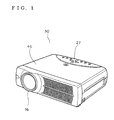
- FIGS. 1 and 2 are diagrams showing a three-chip liquid crystal projector 30 as a projection video display system of the embodiment.
- a body case 40 having a top face in which an operation part 27 is formed an optical system including a light source 1 is housed.
- a light emitting part of the light source 1 is constructed by an extra-high pressure mercury lamp, a metal halide lamp, a xenon lamp, or the like.
- Light emitted from the light emitting part is converted to parallel light by a parabola reflector 2.
- the parallel light goes out and is led to an integrator lens 4.
- the integrator lens 4 is constructed by a pair of lenses (fly-eye lenses) 4a and 4b. Each of the lenses leads the light emitted from the light source 1 to all of surfaces of liquid crystal light bulbs 31, 32, and 33 described later. By the operation, partial brightness unevenness existing in the light source 1 is averaged, and the light amount difference between the center of the screen and the peripheral part is reduced.
- the light that goes out from the integrator lens 4 passes through a polarization converter 5 and a condenser lens 6 and, after that, is led to a first dichroic mirror 7.
- the first dichroic mirror 7 transmits light in a red wavelength band and reflects light in a wavelength band of cyan (green + blue).
- the light in the red wavelength band passed through the first dichroic mirror 7 is reflected by a reflection mirror 8 and its optical path is changed.
- the red light reflected by the reflection mirror 8 passes through a lens 9 and the liquid crystal light bulb 31 as a transmission display device for red light, thereby being subjected to light modulation.
- the light in the cyan wavelength band reflected by the first dichroic mirror 7 is led to a second dichroic mirror 10.
- the second dichroic mirror 10 transmits light in a blue wavelength band and reflects light in a green wavelength band.
- the light in the green wavelength band reflected by the second dichroic mirror 10 is led to the liquid crystal light bulb 32 as a transmission display device for green light via a lens 11.
- the light passes through the liquid crystal light bulb 32 , thereby being subjected to light modulation.
- the light in the blue wavelength band, that has passed through the second dichroic mirror 10 is led via total reflection mirrors 12 and 13 and a lens 14 to the liquid crystal light bulb 33 as a transmission display device for blue light.
- the light passes through the liquid crystal light bulb 33, thereby being subjected to light modulation.
- the liquid crystal light bulbs 31, 32, and 33 are constructed by incident-side sheet polarizers 31a, 32a, and 33a, panels 31b, 32b, and 33b each formed by sealing liquid crystal between a pair of glass substrates (on which pixel electrodes and an orientation film are formed), and outgoing-side sheet polarizers 31c, 32c, and 33c, respectively.
- the modulation light (video light of the colors) modulated by passing through the liquid crystal light bulbs 31, 32, and 33 is combined by a cross dichroic prism 15, thereby obtaining color video image light.
- the color video image light is enlarged and projected by a projection lens 16 to form an image on a not-shown screen.
- cooling air is sent by a cooling fan 5 in FIG. 3 to the liquid crystal light bulbs 31, 32, and 33 to cool the liquid crystal light bulbs 31, 32, and 33.
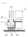
- the air generated by driving the cooling fan 5 is guided to the liquid crystal light bulb 32 (31, 33) via a cooling duct 55 forming an air passage 50 shown in FIG. 3. With the air, the liquid crystal light bulbs 31, 32, and 33 are cooled.
- openings 60 for making the air passage 50 communicate with the outside air are formed in a bottom face 45 of the body case 40 in positions corresponding to the liquid crystal light bulbs 31, 32, and 33 as shown in FIGS. 2 and 3.
- the openings 60 are closed with detachable closing members 70.
- the closing members 70 are detached.
- a balloon-type blower 80 or the like for cleaning a camera or the like is inserted in the opening 60, and air from the blower 80 is blown to the liquid crystal light bulbs 31, 32, and 33. With the air, the dusts adhered to the liquid crystal light bulbs 31, 32, and 33 can be removed.
- the dusts can be removed more easily. Also by increasing the strength of the cooling air of the cooling fan, removal of dusts is facilitated.
- the openings 60 are formed in the bottom face 45 of the body case 40. Therefore, in a normal use state of the projector, the openings 60 are not seen, so that deterioration in appearance can be suppressed. Even in the case where the user forgets about attaching the closing members 70 for closing the openings 60, invasion of dusts from the openings 60 into the body case 40 can be prevented.
- the openings 60 are closed with the closing members 70 except for the time of performing maintenance of removing dusts. Consequently, invasion of dusts from the openings 60 into the body case 40 can be prevented with reliability and entry of outside light from the openings 60 can be also prevented.
- the openings 60 are formed in the bottom face 45 of the body case 40 in the embodiment, the openings 60 may be formed in another face of the body case 40.
- the openings 60 are formed only in positions corresponding to the liquid crystal light bulbs 31, 32, and 33 in the embodiment, the opening 60 may be also formed in a position corresponding to the integrator lens 4 or the like.
- a spray-type air duster or the like may be used as a cleaning tool of removing dusts adhered to the liquid crystal light bulbs 31, 32, and 33.
- the projector of the embodiment of the invention is the three-chip liquid crystal projector of LCD, the invention is not limited to the projector of this type.
- the configuration of the present invention may also be used for a projector of a DLP (Digital Light Processing) (registered trademark of Texas Instruments Inc. (TI)).
- DLP Digital Light Processing
- TI Texas Instruments Inc.
Landscapes
- Engineering & Computer Science (AREA)
- Multimedia (AREA)
- Signal Processing (AREA)
- Physics & Mathematics (AREA)
- General Physics & Mathematics (AREA)
- Projection Apparatus (AREA)
- Liquid Crystal (AREA)
- Devices For Indicating Variable Information By Combining Individual Elements (AREA)
- Transforming Electric Information Into Light Information (AREA)
Abstract
Description
- The present invention relates to a projection video display system such as a projector.
- There is a known projection video display system of this kind in which air generated by driving a sirocco fan having an excellent static pressure characteristic is sent to a liquid crystal light bulb as a display device housed in a body case. Since the liquid crystal light bulb generates heat by light emitted from a light source, by sending cooling air from the sirocco fan to the liquid crystal light bulb, the liquid crystal light bulb can be cooled efficiently (refer to Japanese Patent Laid-Open Publication No. H05-53200).
- During use of the projection video display system, cooling air constantly flows to the liquid crystal light bulb. Therefore, dusts included in the cooling air may be adhered to the liquid crystal light bulb. In the case where dusts are adhered to the liquid crystal light bulb, deterioration in the quality of a projection video image such as disturbance of a projection image occurs. It is consequently necessary to remove the dusts adhered to the liquid crystal light bulb.
- However, the user is not allowed to open the body case housing the liquid crystal light bulb in consideration of maintenance of performance and safety. As a result, the user has to ask a maintenance company to visit for maintenance or has to send the projection video display system to a maintenance company. That is, there is a problem that the work of removing dusts adhered to the liquid crystal light bulb is troublesome.
- The present invention has been achieved to solve such a problem and an object of the invention is to provide a projection video display system in which dusts adhered to a display device can be easily removed by the user with a simple configuration.
- The present invention provides a projection video display system for irradiating display devices with light emitted from a light source housed in a body case and projecting a video image to the outside of the body case, including: a cooling fan for cooling the display devices; and an air passage for guiding air generated by driving the cooling fan to the display devices, wherein openings for making the display devices communicate with outside air are formed in positions corresponding to at least the display devices in the body case.
- The openings may be formed in the bottom face of the body case. The openings may be closed with detachable closing members.
- With the configuration of a first aspect of the present invention, dusts adhered to the display devices can be removed without opening the body case. Consequently, effects are produced such that it is unnecessary to ask a maintenance company for maintenance and the user can easily perform maintenance.
- With the configuration of a second aspect of the present invention, the openings are formed in the bottom face of the body case. In a normal use state, the openings are in the blind spot, so that deterioration in appearance can be suppressed.
- With the configuration of a third aspect of the present invention, the openings are closed with the closing members except for the time when maintenance is performed. Thus, invasion of dusts from the openings into the body case can be prevented with reliability.
-
- FIG. 1 is an outside perspective view of a projection video display system of an embodiment of the present invention;
- FIG. 2 is a configuration diagram showing an optical system of the projection video display system;
- FIG. 3 is a cross section of an air passage in the projection video display system;
- FIG. 4 is a rear view of the projection video display system; and
- FIG. 5 is an outside view of a blower as a cleaning tool of the projection video display system.
- A projection video display system of an embodiment of the present invention will be described in detail hereinbelow with reference to FIGS. 1 to 5.
- FIGS. 1 and 2 are diagrams showing a three-chip
liquid crystal projector 30 as a projection video display system of the embodiment. In abody case 40 having a top face in which anoperation part 27 is formed, an optical system including alight source 1 is housed. A light emitting part of thelight source 1 is constructed by an extra-high pressure mercury lamp, a metal halide lamp, a xenon lamp, or the like. Light emitted from the light emitting part is converted to parallel light by aparabola reflector 2. The parallel light goes out and is led to anintegrator lens 4. - The
integrator lens 4 is constructed by a pair of lenses (fly-eye lenses) 4a and 4b. Each of the lenses leads the light emitted from thelight source 1 to all of surfaces of liquidcrystal light bulbs light source 1 is averaged, and the light amount difference between the center of the screen and the peripheral part is reduced. The light that goes out from theintegrator lens 4 passes through apolarization converter 5 and acondenser lens 6 and, after that, is led to a first dichroic mirror 7. - The first dichroic mirror 7 transmits light in a red wavelength band and reflects light in a wavelength band of cyan (green + blue). The light in the red wavelength band passed through the first dichroic mirror 7 is reflected by a reflection mirror 8 and its optical path is changed. The red light reflected by the reflection mirror 8 passes through a
lens 9 and the liquidcrystal light bulb 31 as a transmission display device for red light, thereby being subjected to light modulation. The light in the cyan wavelength band reflected by the first dichroic mirror 7 is led to a seconddichroic mirror 10. - The second
dichroic mirror 10 transmits light in a blue wavelength band and reflects light in a green wavelength band. The light in the green wavelength band reflected by the seconddichroic mirror 10 is led to the liquidcrystal light bulb 32 as a transmission display device for green light via alens 11. The light passes through the liquidcrystal light bulb 32 , thereby being subjected to light modulation. The light in the blue wavelength band, that has passed through the seconddichroic mirror 10 is led viatotal reflection mirrors lens 14 to the liquidcrystal light bulb 33 as a transmission display device for blue light. The light passes through the liquidcrystal light bulb 33, thereby being subjected to light modulation. - The liquid
crystal light bulbs panels 31b, 32b, and 33b each formed by sealing liquid crystal between a pair of glass substrates (on which pixel electrodes and an orientation film are formed), and outgoing-side sheet polarizers 31c, 32c, and 33c, respectively. - The modulation light (video light of the colors) modulated by passing through the liquid
crystal light bulbs dichroic prism 15, thereby obtaining color video image light. The color video image light is enlarged and projected by aprojection lens 16 to form an image on a not-shown screen. - There is the possibility that the liquid
crystal light bulbs light source 1 and their performance deteriorates. Consequently, cooling air is sent by acooling fan 5 in FIG. 3 to the liquidcrystal light bulbs crystal light bulbs cooling fan 5 is guided to the liquid crystal light bulb 32 (31, 33) via acooling duct 55 forming anair passage 50 shown in FIG. 3. With the air, the liquidcrystal light bulbs - Since the cooling air always flows to the liquid
crystal light bulbs crystal light bulbs crystal light bulbs crystal light bulbs - As a countermeasure, in the embodiment,
openings 60 for making theair passage 50 communicate with the outside air are formed in abottom face 45 of thebody case 40 in positions corresponding to the liquidcrystal light bulbs openings 60 are closed withdetachable closing members 70. - With this configuration, when the user recognizes deterioration in the quality of a projected video image such as disturbance in the projected video image, first, the
closing members 70 are detached. Next, for example, as shown in FIG. 5, a balloon-type blower 80 or the like for cleaning a camera or the like is inserted in theopening 60, and air from theblower 80 is blown to the liquidcrystal light bulbs crystal light bulbs - At this time, by displaying a projected video image in a painted manner, leakage of light that is reflected irregularly by the dusts adhered to the liquid
crystal light bulbs crystal light bulbs - By adjusting the length of the tip portion of the
blower 80 so that the exhaust nozzle comes closer to the liquid crystallight bulb 32, the dusts can be removed more easily. Also by increasing the strength of the cooling air of the cooling fan, removal of dusts is facilitated. - By providing a gap between the
blower 80 and theopening 60 so that the position of the tip portion of theblower 80 can be freely adjusted, dusts can be removed from all of the areas of the liquidcrystal light bulbs - In such a manner, dusts adhered to the liquid
crystal light bulbs body case 40. Consequently, unlike the conventional technique, it is unnecessary to ask a maintenance company for maintenance, and the user can easily perform maintenance. Moreover, it is unnecessary to open thebody case 40 in order to perform maintenance. Maintenance can be performed in a state where current is passed to the projection video display system. Therefore, maintenance can be performed in a state where a projected video image is displayed in a painted manner, so that a maintenance work can be simplified. - The
openings 60 are formed in thebottom face 45 of thebody case 40. Therefore, in a normal use state of the projector, theopenings 60 are not seen, so that deterioration in appearance can be suppressed. Even in the case where the user forgets about attaching the closingmembers 70 for closing theopenings 60, invasion of dusts from theopenings 60 into thebody case 40 can be prevented. - The
openings 60 are closed with the closingmembers 70 except for the time of performing maintenance of removing dusts. Consequently, invasion of dusts from theopenings 60 into thebody case 40 can be prevented with reliability and entry of outside light from theopenings 60 can be also prevented. - Although the
openings 60 are formed in thebottom face 45 of thebody case 40 in the embodiment, theopenings 60 may be formed in another face of thebody case 40. - Although the
openings 60 are formed only in positions corresponding to the liquidcrystal light bulbs opening 60 may be also formed in a position corresponding to theintegrator lens 4 or the like. As a cleaning tool of removing dusts adhered to the liquidcrystal light bulbs - Although the projector of the embodiment of the invention is the three-chip liquid crystal projector of LCD, the invention is not limited to the projector of this type. The configuration of the present invention may also be used for a projector of a DLP (Digital Light Processing) (registered trademark of Texas Instruments Inc. (TI)).
Claims (4)
- A projection video display system for irradiating display devices 31, 32, and 33 with light emitted from a light source housed in a body case 40 and projecting a video image to the outside of the body case 40, comprising:a cooling fan 5 for cooling the display devices 31, 32, and 33; andan air passage for guiding air generated by driving the cooling fan 5 to the display devices 31, 32, and 33,wherein openings 60 for making the display devices 31, 32, and 33 communicate with outside air are formed in positions corresponding to at least said display devices 31, 32, and 33 in the body case 40.
- The projection video display system according to claim 1, wherein said openings 60 are formed in a bottom face of the body case 40.
- The projection video display system according to claim 1, wherein said openings 60 are closed with detachable closing members 70.
- The projection video display system according to claim 2, wherein said openings 60 are closed with detachable closing members 70.
Applications Claiming Priority (1)
| Application Number | Priority Date | Filing Date | Title |
|---|---|---|---|
| JP2004212581A JP4511269B2 (en) | 2004-07-21 | 2004-07-21 | Projection display device |
Publications (2)
| Publication Number | Publication Date |
|---|---|
| EP1619890A2 true EP1619890A2 (en) | 2006-01-25 |
| EP1619890A3 EP1619890A3 (en) | 2007-12-05 |
Family
ID=35106762
Family Applications (1)
| Application Number | Title | Priority Date | Filing Date |
|---|---|---|---|
| EP05015786A Withdrawn EP1619890A3 (en) | 2004-07-21 | 2005-07-20 | Projection video display system |
Country Status (6)
| Country | Link |
|---|---|
| US (1) | US7753566B2 (en) |
| EP (1) | EP1619890A3 (en) |
| JP (1) | JP4511269B2 (en) |
| KR (1) | KR100730879B1 (en) |
| CN (1) | CN100451823C (en) |
| TW (1) | TWI314239B (en) |
Cited By (1)
| Publication number | Priority date | Publication date | Assignee | Title |
|---|---|---|---|---|
| EP2187260A3 (en) * | 2008-11-13 | 2012-12-19 | Mitsubishi Electric Corporation | Image display apparatus |
Families Citing this family (8)
| Publication number | Priority date | Publication date | Assignee | Title |
|---|---|---|---|---|
| JP2010181587A (en) * | 2009-02-05 | 2010-08-19 | Sony Corp | Light modulator and projection-type display apparatus |
| US8662674B2 (en) * | 2009-03-26 | 2014-03-04 | Nec Display Solutions, Ltd. | Method for controlling cooling device, cooling device, and projection-type display device |
| JP2011123177A (en) * | 2009-12-09 | 2011-06-23 | Sanyo Electric Co Ltd | Projection-type video display apparatus |
| US8585242B2 (en) * | 2010-02-04 | 2013-11-19 | Sternberg Lanterns, Inc. | Lighting system with light-emitting diodes and securing structure |
| CN102854720B (en) * | 2011-06-30 | 2014-10-22 | 中强光电股份有限公司 | Dust removal module and projection device |
| CN104028504A (en) * | 2013-03-04 | 2014-09-10 | 台达电子工业股份有限公司 | Cleaning module suitable for projection device |
| EP3625791B1 (en) * | 2017-05-18 | 2025-09-03 | Telepathy Labs, Inc. | Artificial intelligence-based text-to-speech system and method |
| CN113433780B (en) * | 2021-05-17 | 2022-09-30 | 重庆市永川职业教育中心 | Teaching demonstration ware suitable for electronic technology uses |
Family Cites Families (26)
| Publication number | Priority date | Publication date | Assignee | Title |
|---|---|---|---|---|
| GB300449A (en) * | 1928-03-12 | 1928-11-15 | Edward George Turner | Improvements in and connected with safety devices for use with kinematograph projectors |
| US3433564A (en) * | 1966-06-15 | 1969-03-18 | Ibm | Vacuum transparency holder and optics |
| US3872235A (en) * | 1974-02-04 | 1975-03-18 | Lawrence Peska Ass Inc | Inflatable housing for an electricity consuming device |
| US4008654A (en) * | 1975-06-04 | 1977-02-22 | Emerson Electric Co. | Adjustable air blade for air handling luminaires |
| JPS61149942A (en) * | 1984-12-25 | 1986-07-08 | Canon Inc | Film projection device |
| JPH07122698B2 (en) * | 1988-02-25 | 1995-12-25 | 松下電器産業株式会社 | Projection display device |
| JPH04130952U (en) * | 1991-05-23 | 1992-12-01 | 横河電機株式会社 | lcd projector |
| JPH0553200A (en) * | 1991-08-28 | 1993-03-05 | Toshiba Corp | Projection type video display device |
| JPH063644A (en) * | 1992-06-23 | 1994-01-14 | Casio Comput Co Ltd | Liquid crystal projector |
| JPH09189962A (en) * | 1996-01-09 | 1997-07-22 | Hitachi Ltd | Projection display device |
| US6109767A (en) * | 1996-03-29 | 2000-08-29 | Minnesota Mining And Manufacturing Company | Honeycomb light and heat trap for projector |
| TW461949B (en) * | 1997-07-31 | 2001-11-01 | Plus Kk | Lamp cartridge |
| JP2000321668A (en) * | 1999-05-13 | 2000-11-24 | Sony Corp | Image display device and method |
| JP2001133885A (en) * | 1999-08-26 | 2001-05-18 | Mitsubishi Electric Corp | projector |
| JP2002006283A (en) * | 2000-06-27 | 2002-01-09 | Toshiba Corp | LCD projector device |
| JP3664065B2 (en) * | 2000-09-29 | 2005-06-22 | セイコーエプソン株式会社 | Light source device and projector |
| JP2002258399A (en) * | 2001-02-28 | 2002-09-11 | Mitsubishi Electric Corp | Projection type image display device |
| JP3467697B2 (en) * | 2001-05-16 | 2003-11-17 | セイコーエプソン株式会社 | Cooling device for electro-optical device and projector |
| JP4796709B2 (en) * | 2001-05-25 | 2011-10-19 | Necディスプレイソリューションズ株式会社 | LCD projector |
| JP2003063778A (en) * | 2001-08-28 | 2003-03-05 | Tadano Ltd | Mobile crane |
| JP3977054B2 (en) * | 2001-11-01 | 2007-09-19 | キヤノン株式会社 | Projector device |
| JP2003337377A (en) * | 2002-03-13 | 2003-11-28 | Seiko Epson Corp | Rear projector |
| JP3758622B2 (en) * | 2002-08-08 | 2006-03-22 | セイコーエプソン株式会社 | Optical device, optical unit, and projector |
| US7086740B2 (en) * | 2003-06-02 | 2006-08-08 | Infocus Corporation | Injection-molded vent screens |
| JP4265289B2 (en) * | 2003-06-05 | 2009-05-20 | 株式会社日立製作所 | Projection display |
| JP7333944B2 (en) * | 2019-06-27 | 2023-08-28 | 株式会社フジキン | Fluid control device |
-
2004
- 2004-07-21 JP JP2004212581A patent/JP4511269B2/en not_active Expired - Fee Related
-
2005
- 2005-05-25 TW TW094117006A patent/TWI314239B/en not_active IP Right Cessation
- 2005-07-06 CN CNB2005100826667A patent/CN100451823C/en not_active Expired - Fee Related
- 2005-07-19 KR KR1020050065109A patent/KR100730879B1/en not_active Expired - Fee Related
- 2005-07-20 EP EP05015786A patent/EP1619890A3/en not_active Withdrawn
- 2005-07-20 US US11/184,876 patent/US7753566B2/en not_active Expired - Lifetime
Cited By (1)
| Publication number | Priority date | Publication date | Assignee | Title |
|---|---|---|---|---|
| EP2187260A3 (en) * | 2008-11-13 | 2012-12-19 | Mitsubishi Electric Corporation | Image display apparatus |
Also Published As
| Publication number | Publication date |
|---|---|
| CN100451823C (en) | 2009-01-14 |
| US20060018124A1 (en) | 2006-01-26 |
| CN1725102A (en) | 2006-01-25 |
| KR20060053877A (en) | 2006-05-22 |
| JP4511269B2 (en) | 2010-07-28 |
| JP2006030827A (en) | 2006-02-02 |
| KR100730879B1 (en) | 2007-06-20 |
| EP1619890A3 (en) | 2007-12-05 |
| TWI314239B (en) | 2009-09-01 |
| TW200604711A (en) | 2006-02-01 |
| US7753566B2 (en) | 2010-07-13 |
Similar Documents
| Publication | Publication Date | Title |
|---|---|---|
| JP3467697B2 (en) | Cooling device for electro-optical device and projector | |
| KR100491240B1 (en) | Optical part mounting structure and projector | |
| JP3995685B2 (en) | Projection display device | |
| JP3700571B2 (en) | Projection display | |
| JP3724532B2 (en) | Image display device and cooling device for optical device | |
| JP2008257175A (en) | Power source unit and projection type image display apparatus using the same | |
| WO2002097529A1 (en) | Projector | |
| JP2004258211A (en) | Light source device and projector | |
| JP5140379B2 (en) | Optical component cooling mechanism and projection display apparatus using the same | |
| US7364308B2 (en) | Projector apparatus | |
| US7753566B2 (en) | Projection video display system | |
| US7314280B2 (en) | Projector apparatus | |
| JP4366618B2 (en) | LCD projector | |
| JP2008257173A (en) | Light source lamp cooling mechanism and projection display apparatus using the same | |
| JP2003107581A (en) | Rear projection type projector device | |
| JP2008281970A (en) | Projector apparatus | |
| JP3741145B2 (en) | Projection display | |
| JP3558084B2 (en) | projector | |
| JP2004061894A (en) | LCD projector | |
| JP2002150832A (en) | Projection display device | |
| JP2007212568A (en) | Projection type image display device | |
| JP4055420B2 (en) | Light source device and projector provided with the light source device | |
| JP2008191532A (en) | Rear projector | |
| JP2004246059A (en) | Optical component housing, optical unit, and projector | |
| JP2011150141A (en) | Image projection device |
Legal Events
| Date | Code | Title | Description |
|---|---|---|---|
| PUAI | Public reference made under article 153(3) epc to a published international application that has entered the european phase |
Free format text: ORIGINAL CODE: 0009012 |
|
| AK | Designated contracting states |
Kind code of ref document: A2 Designated state(s): AT BE BG CH CY CZ DE DK EE ES FI FR GB GR HU IE IS IT LI LT LU LV MC NL PL PT RO SE SI SK TR |
|
| AX | Request for extension of the european patent |
Extension state: AL BA HR MK YU |
|
| PUAL | Search report despatched |
Free format text: ORIGINAL CODE: 0009013 |
|
| AK | Designated contracting states |
Kind code of ref document: A3 Designated state(s): AT BE BG CH CY CZ DE DK EE ES FI FR GB GR HU IE IS IT LI LT LU LV MC NL PL PT RO SE SI SK TR |
|
| AX | Request for extension of the european patent |
Extension state: AL BA HR MK YU |
|
| 17P | Request for examination filed |
Effective date: 20080318 |
|
| AKX | Designation fees paid |
Designated state(s): DE FR GB SE |
|
| 17Q | First examination report despatched |
Effective date: 20080812 |
|
| STAA | Information on the status of an ep patent application or granted ep patent |
Free format text: STATUS: THE APPLICATION HAS BEEN WITHDRAWN |
|
| 18W | Application withdrawn |
Effective date: 20130708 |