EP1619762A2 - Card socket - Google Patents
Card socket Download PDFInfo
- Publication number
- EP1619762A2 EP1619762A2 EP05014673A EP05014673A EP1619762A2 EP 1619762 A2 EP1619762 A2 EP 1619762A2 EP 05014673 A EP05014673 A EP 05014673A EP 05014673 A EP05014673 A EP 05014673A EP 1619762 A2 EP1619762 A2 EP 1619762A2
- Authority
- EP
- European Patent Office
- Prior art keywords
- card
- rocker arm
- slider
- pressed
- plate portion
- Prior art date
- Legal status (The legal status is an assumption and is not a legal conclusion. Google has not performed a legal analysis and makes no representation as to the accuracy of the status listed.)
- Granted
Links
Images







Classifications
-
- G—PHYSICS
- G06—COMPUTING OR CALCULATING; COUNTING
- G06K—GRAPHICAL DATA READING; PRESENTATION OF DATA; RECORD CARRIERS; HANDLING RECORD CARRIERS
- G06K13/00—Conveying record carriers from one station to another, e.g. from stack to punching mechanism
- G06K13/02—Conveying record carriers from one station to another, e.g. from stack to punching mechanism the record carrier having longitudinal dimension comparable with transverse dimension, e.g. punched card
- G06K13/08—Feeding or discharging cards
- G06K13/0806—Feeding or discharging cards using an arrangement for ejection of an inserted card
-
- G—PHYSICS
- G06—COMPUTING OR CALCULATING; COUNTING
- G06K—GRAPHICAL DATA READING; PRESENTATION OF DATA; RECORD CARRIERS; HANDLING RECORD CARRIERS
- G06K13/00—Conveying record carriers from one station to another, e.g. from stack to punching mechanism
- G06K13/02—Conveying record carriers from one station to another, e.g. from stack to punching mechanism the record carrier having longitudinal dimension comparable with transverse dimension, e.g. punched card
- G06K13/08—Feeding or discharging cards
Definitions
- the present invention relates to a card socket which contains a card ejection mechanism.
- the card socket is also referred to as a card connector.
- a small-sized device such as a cellular phone and a digital camera, comprises a card socket for removably holding a small-sized memory card, which is smaller than a PC card.
- a card socket of this type is disclosed in JP-A 2001-351735.
- the card socket comprises a card ejection mechanism and an operation member.
- the card ejection mechanism is activated when the operation member is moved along a thickness direction of the card socket.
- the card socket further comprises a specific structure, which is disclosed in JP-A 2001-351735, for example, paragraph 0046.
- JP-A 2001-351735 for example, paragraph 0046.
- a card socket according to an embodiment of the present invention is described in detail below.
- the card socket 100 comprises a case 30, a slider 40, a first compression spring 50, a rocker arm 60, a second compression spring 70 and a button 80.
- the case 30 comprises an insulator 10 and a cover 20.
- the insulator 10 comprises an edge 10a, a portion 10b, and a bottom portion 11.
- the edge 10a constitutes a rear end of the insulator 10 in a Y-direction.
- the portion 10b further projects outwardly of the insulator 10 in comparison with the edge 10a.
- the cover 20 comprises an edge 20a and a portion 20b.
- the edge 20a constitutes a rear end of the cover 20 in the Y-direction.
- the portion 20b further projects outwardly of the cover 20 in comparison with the edge 20a.
- the bottom portion 11 and the cover 20 define a card housing space 32, which can accommodate a card.
- the edge 10a and the edge 20a define an open end 34.
- the open end 34 has a rectangular shape, which is long in an X-direction and is short in a Z-direction. With reference to Fig. 15, the open end 34 allows a card 200 to be inserted into the card housing space 32 and to be ejected from the card housing space 32 along the Y-direction.
- the insulator 10 holds a plurality of terminals 36, while a free end of the each terminal 36 projects inwardly of the card housing space 32 in the Z-direction so that the each terminal 36 has resilience.
- the card 200 is pressed on the cover 20 by the terminals 36 when the card 200 is inserted into the card housing space 32.
- the insulator 10 comprises a first wall 12, a second wall 13 and a third wall 14.
- the first to the third walls 12 to 14 surround three sides of the bottom portion 11.
- the bottom portion 11 comprises a first bottom portion 11a and a second bottom portion 11b.
- the first bottom portion 11a constitutes the bottom surface of the card housing space 32.
- the second bottom portion 11b is concaved by a predetermined depth in comparison with the first bottom portion 11 a.
- the predetermined depth is equal to the thickness of the rocker arm 60 in the Z-direction.
- the second bottom portion 11b rockably accommodates the rocker arm 60.
- the second bottom portion 11b is formed with a pivot 11c.
- the pivot 11c is positioned nearly at the center of the second bottom portion 11b in the Y-direction.
- the pivot 11c projects in the Z-direction and has a short cylindrical shape.
- the pivot 11c constitutes a fulcrum of rocking movement of the rocker arm 60, as described later.
- the bottom portion 11 of the insulator 10 is formed with a through hole 11d, which has a staircase-like shape of a single step. The position of the through hole 11d is the border between the first bottom portion 11a and the second bottom portion 11b and around the pivot 11c.
- the second wall 13 is placed at the farthest region from the open end 34 in the Y-direction.
- the second wall 13 comprises a thick wall 13a, a thin wall 13b and a guide rail 13c.
- the thick wall 13a is thicker than the thin wall 13b.
- the guide rail 13c is located far from the thin wall 13b by a predetermined distance.
- the guide rail 13c projects from the second bottom portion 11b in the Z-direction.
- the thin wall 13b and the guide rail 13c extend from the thick wall 13a along the X-direction.
- the thin wall 13b and the guide rail 13c define a spring accommodation ditch 13d therebetween.
- a spring accommodation hole 13e extends into the thick wall 13a along the X-direction.
- the spring accommodation ditch 13d and the spring accommodation hole 13e form a spring accommodation portion 13f.
- the spring accommodation portion 13 f accommodates the second compression spring 70.
- the third wall 14 comprises a first portion 14a, a second portion 14b, a third portion 14c, a groove portion 14d, and a fourth portion 14e.
- the first portion 14a extends from the second wall 13 in the Y-direction.
- the second portion 14b is thicker than the first portion 14a in the X-direction.
- the third portion 14c is lower than the second portion 14b in the Z-direction.
- the groove portion 14d is formed in the third portion 14c and extends in the Y-direction.
- the depth direction of the groove portion 14d is the Z-direction.
- the fourth portion 14e extends from the third portion 14c along the Y-direction. As best shown in Fig. 4, an inner surface of the fourth portion 14e and an inner surface of the groove portion 14d are in line with each other, as seen from the Z-direction.
- the second bottom portion 11b is provided with an island portion 15.
- the pivot 11c is placed between the card housing space 32 and the island portion 15 in the X-direction.
- the illustrated island portion 15 is placed on the rear half of the insulator 10 in the Y-direction.
- the island portion 15 has the same height as that of the pivot 11c.
- the island portion 15 is provided with a standing wall 15a, an edge portion 15b, a plateau portion 15c and a portion 15d.
- the standing wall 15a is placed at the nearest position to the pivot 11 c on the island portion 15 and extends along the Y-direction. As described later, the standing wall 15a and the second portion 14b form a guide portion for receiving a rear portion of the slider 40.
- the edge portion 15b constitutes the front end of the island portion 15 and defines an end position of the slider 40.
- the plateau portion 15c is placed on an end portion of the island portion 15 in the Y-direction and protrudes in the Z-direction.
- the plateau portion 15c has the same height as that of the third portion 14c of the third wall 14.
- the portion 15d constitutes a side surface of the island portion 15, which is positioned near the plateau portion 15c.
- the portion 15d is perpendicular to the X-Y plane and extends diagonally across the X- and the Y-directions.
- the insulator 10 is further provided with a first projection portion 16.
- the first projection portion 16 is formed on the second bottom portion 11b and is positioned away from the island portion 15 in the Y-direction.
- the first projection portion 16 has an L-shaped cross-section in the X-Z plane.
- the first projection portion 16 projects from the second bottom portion 11b in the Z-direction and then projects in the X-direction.
- the first projection portion 16 and the second bottom portion 11b form a gap 16a therebetween.
- the gap 16a accommodates a part of the rocker arm 60, as described later.
- the gap 16a described in this embodiment is slightly larger than the thickness of the rocker arm 60.
- the first projection portion 16 is provided with a portion 16b.
- the portion 16b is perpendicular to the second bottom portion 11b and faces the gap 16a.
- the portion 16b and the portion 15d are substantially in line with each other.
- the first projection portion 16 is positioned with a predetermined distance left between the fourth portion 14e of the third wall 14 and the first projection portion 16.
- the predetermined distance is the same as the width of the groove portion 14d in the X-direction.
- the first projection portion 16 and the island portion 15 define a first region 11e therebetween. The role of the first region 11e will be described with the rocker arm 60.
- the insulator 10 further comprises a second projection portion 17.
- the second projection portion 17 is placed away from the first projection portion 16 in the Y-direction.
- the first projection portion 16 is placed between the island portion 15 and the second projection portion 17.
- the second projection portion 17 projects from the bottom portion 11 in the Z-direction.
- the second projection portion 17 is placed with the predetermined distance left between the fourth portion 14e of the third wall 14 and the second projection portion 17.
- the second projection portion 17 and the first projection portion 16d define a second region 11f therebetween.
- the role of the second region 1f will be described with the rocker arm 60.
- the second projection potion 17 is positioned on the portion 10b.
- the portion 10b and the portion 20b form an overhanging portion 38.
- the overhanging portion 38 sticks out from the open end 34 in the Y-direction.
- the function of the overhanging portion 38 will be described with a press operation of the button 80.
- the cover 20 comprises a cantilever spring 22 and a guide plate 24.
- the cantilever spring 22 is arranged to face the groove portion 14d of the insulator 10.
- the cantilever spring 22 extends inwardly of the case 30 and in the direction of the insertion of the card.
- the cantilever spring 22 urges the button 80 to project from the case 30 in the Y-direction.
- the guide plate 24 is flat and extends from the cover 20 inwardly of the case 30 in the Z-direction and also extends in the Y-direction.
- the guide plate 24 is obtainable by making an angular U-shaped cut into the main surface of the cover 20 to form a plate portion, followed by bending the plate portion inwardly of the case 30.
- the slider 40 comprises a main portion 41 and a transmission portion 42.
- the main portion 41 has a rectangular parallelepiped shape which is long in the Y-direction.
- the transmission portion 42 projects from the main portion 41 in the X-direction.
- the slider 40 is provided with a guided slit portion 43, which is formed between the main portion 41 and the transmission portion 42.
- the guided slit portion 43 receives the guide plate 24 of the cover 20.
- a projection portion 44 projects in the Z-direction.
- the projection portion 44 has a rectangular cross-section in the X-Y plane.
- the projection portion 44 is slidable on the second bottom portion 11b. In this embodiment, a projection amount of the projection portion 44 is as much as the thickness of the rocker arm 60.
- the main portion 41 of the slider 40 is provided with a guided portion 45, which constitutes the rear end portion of the main portion 41.
- the guided portion 45 is narrower than the other part.
- the guided portion 45 has shoulder portions 46 and 47.
- the guided portion 45 is accommodated in the guide portion defined by the standing wall 15a of the island portion 15 and the second portion 14b of the third wall 14.
- the guide portion, the guide plate 24 of the cover 20 and the guided slit portion 43 of the slider 40 prevents the slider 40 from moving in the X-direction even if the slider 40 receives a force in the X-direction.
- a position of the slider 40 is referred to as a first position, at which the slider 40 is positioned when the card 200 is completely inserted into the case 30.
- Another position of the slider 40 is referred to as a second position, at which the slider 40 is prevented from sliding backward in the Y-direction by the island portion 15 and so on.
- the slider 40 is provided with a hole 48.
- the hole 48 is formed in the main portion 41 and extends in the Y-direction.
- the hole 48 receives the first compression spring 50 therein.
- the first compression spring 50 is mounted on the insulator 10 together with the slider 40 and urges the slider 40 to move toward the second position.
- the transmission portion 42 of the slider 40 is placed above the spring accommodation portion 13 f of the insulator 10 in the Z-direction, as understood from Figs. 18 and 20, when the card 200 is inserted into the case 30 and the slider 40 is positioned at the first position. In this event, the transmission portion 42 is not in contact with the guide rail 13c and the second compression spring 70. Thus, the projection area of the card socket 100 is downsized.
- the rocker arm 60 comprises a main plate 61.
- the main plate 61 comprises a first end portion 61b and a second end portion 61 c.
- the main plate 61 is formed with a pivot opening 61a, which is positioned between the first end portion 61b and the second end portion 61 c.
- the first end portion 61a is formed with a first pressed portion 62, which has a U-shaped cross-section. The bottom of the U-shape of the first pressed portion 62 projects upwards in the Z-direction.
- the second end portion 61 c of the main plate 61 is formed with a posterior edge receiving portion 63.
- the posterior edge receiving portion 63 projects from the second end portion 61c in the Z-direction.
- the posterior edge receiving portion 63 receives the posterior edge of the card 200 and prevents the card 200 from falling out of the card housing space 32.
- the rocker arm 60 is further provided with a second pressed portion 64, which is positioned between the pivot opening 61a and the second end portion 61c and projects in the Z-direction.
- the main plate 61 comprises a first plate portion 61d, a second plate portion 61e and a third plate portion 61f.
- the first plate portion 61d comprises a narrow plate portion 61d3 and a wide plate portion 61d4.
- the narrow plate portion 61d3 is placed between the pivot opening 61a and the wide plate portion 61d4.
- the wide plate portion 61d4 is placed between the narrow plate portion 6 1 d3 and the second plate portion 61e.
- the second plate portion 61e has an L-like shape.
- the front edge of the first plate portion 61d is slightly carved. As described later, the front edge of the first plate portion 61d receives the projection portion 44 of the slider 40 in the Y-direction when the slider 40 is positioned at the first position.
- the front edge of the first plate portion 61d serves as a stopper 61d1 which prevents the slider 40 from sliding toward the second position.
- the third plate portion 61f extends from the first plate portion 61d with the pivot opening 61a positioned therebetween.
- the first plate portion 61d and the third plate portion 61f are not arranged on a straight line.
- the first plate portion 61d and the second plate portion 61e form a dogleg shape.
- the main plate 61 comprises a restriction portion 65.
- the restriction portion 65 is placed near the pivot opening 61a and projects in the Z-direction. In detail, the restriction portion 65 projects opposite to the projecting direction of the first and the second pressed portions 62 and 64 and the posterior edge receiving portion 63.
- the pivot 11c is rotatably fitted into the pivot opening 61a so that the rocker arm 60 is held on the second bottom portion 11b of the insulator 10.
- the restriction portion 65 is accommodated in the through hole 11d of the insulator 10.
- the restriction portion 65 restricts the rocking movement of the rocker arm 60 and allows the main plate 61 to rock in a plane parallel to the second bottom portion 1b of the insulator 10, i.e., the X-Y plane.
- the rockable range of the rocker arm 60 is defined by and the first plate portion 61d and the third plate portion 61f the step height between the first bottom portion 11a and the second bottom portion 11b.
- the rocker arm 60 when the third plate portion 61f of the rocker arm 60 is brought into contact with the first bottom portion 11a in the X-direction as shown in Fig.19, the rocker arm 60 is placed at a first rock position.
- the rocker arm 60 When the first plate portion 61d of the rocker arm 60 is brought into contact with the first bottom portion 11a in the X-direction, as shown in Fig. 16, the rocker arm 60 is placed at a second rock position.
- the first pressed portion 62 of the rocker arm 60 is arranged to straddle the guide rail 13c of the insulator 10 to be brought into contact with the second compression spring 70 in the X-direction.
- the first pressed portion 62 receives a force from the second compression spring 70 to move toward the slider 40.
- the second compression spring 70 constitutes, in cooperation with the spring accommodation portion 13f, a second urging portion 71 and urges the rocker arm 60 to move toward the first rock position.
- the second pressed portion 64 is movable in the first region 11e
- the posterior edge receiving portion 63 is movable in the second region 11f. Because the first region 11e, the second region 11f and the gap 16a is provided for the insulator 10, the second pressed portion 64 and the posterior edge receiving portion 63 can move smoothly during the rock movement of the rocker arm 60 between the first rock position and the second rock position.
- the first plate portion 61 d of the rocker arm 60 extends toward the second wall 13 along the Y-direction.
- the edge portion 6 1 d2 of the wide plate portion 6 1 d4 projects toward the third wall 14.
- the second plate portion 61e extends from the end portion of the first plate portion 61d in the X-direction away from the slider 40 and then extends toward the second wall 13 in the Y-direction.
- the third plate portion 61 f extends toward the open end 34 along the Y-direction.
- the rocker arm 60 and the slider 40 move as shown in Fig. 14.
- the slider 40 at the first position is shown by the dashed line.
- the slider 40 at the second position is shown by the solid line.
- the rocker arm 60 at the first rock position is shown by the dashed line.
- the rocker arm 60 at the second rock position is shown by the solid line.
- the rocker arm 60 receives from the second compression spring 70a a force which is shown by the outlined arrow, wherein the force is hereinafter referred to as a first force.
- the rocker arm 60 is prevented from rocking toward the first rock position by the projection portion 44 of the slider 40.
- the rocker arm 60 is allowed to rock toward the first rock position from the second rock position. The rocker arm 60 at the first rock position prevents the slider 40 from sliding to the second position.
- the button 80 serves as a portion for providing the second force to the second pressed portion 64 of the rocker arm 60.
- the button 80 comprises a main portion 81 and a pressed portion 82.
- the main portion 81 is a rectangular plate.
- the pressed portion 82 is formed at the rear end of the main position 81.
- the pressed portion 82 projects out from the case 30 along the Y-direction, when the card is completely inserted into the case 30.
- the projecting direction of the pressed portion 82 is referred to as a card ejection direction.
- the pressed portion 82 is pressed by a user for ejecting the inserted card from the case 30 in the card ejection direction.
- the button 80, especially the main portion 81, and the main portion 41 of the slider 40 are arranged on an imaginal straight line in the Y-direction.
- the imaginal straight line is laid on the outside region of the card housing space 32 in the X-direction so that the card 200 is not in contact with the button 80 and the main portion 41 of the slider 40 upon the insertion or the ejection of the card 200.
- the pivot opening 61 a of the rocker arm 60 and the pivot 11c of the insulator 10 are placed away from the imaginal straight line in the X-direction.
- the pivot opening 61 a of the rocker arm 60 and the pivot 11c of the insulator 10 are placed inwardly of the case 30 in the X-direction, as seen from the imaginal straight line.
- the main portion 81 of the button 80 is formed with an accommodation portion 83.
- the accommodation portion 83 accommodates the second pressed portion 64 of the rocker arm 60.
- the accommodation portion 83 is a through-hole in the Z-direction.
- the button 80 is further formed with a space 84, which is positioned between the accommodation portion 83 and the pressed portion 82, as shown in Fig. 12.
- the space 84 accommodates the posterior edge receiving portion 63 of the rocker arm 60 when the rocker arm 60 is positioned at the second rock position.
- the lower surface 81a of the main portion 81 is lower than the upper surface 84a of the space 84 in the Z-direction.
- the lower surface 81a of the main portion 81 and the upper surface of the plateau portion 15c are placed on the same level in the Z-direction when the button 80 is mounted on the insulator 10.
- the upper surface 84a of the space 84 and the upper surface of the first projection portion 16 are placed on the same level in the Z-direction when the button 80 is mounted on the insulator 10.
- the pressed portion 82 is formed with a projection-accommodation portion 82a.
- the projection-accommodation portion 82a accommodates the second projection portion 17 of the insulator 10 when the button 80 is pressed into the case 30 in the Y-direction.
- the projection-accommodation portion 82a accommodates the second projection portion 17
- the button 80 is prevented from being further pressed into the case 30 in the Y-direction.
- the second projection portion 17 prevents the forward movement of the button 80 over the second projection portion 17 in the Y-direction.
- a projection head 85 projects in the Y-direction, as shown in Figs. 8 and 9.
- the projection head 85 comprises a first portion 85a and a second portion 85b.
- the first portion 85a has a rectangle-like shape and projects from the main portion 81 in the Y-direction.
- the second portion 85b further projects from the first portion 85a forward in the Y-direction.
- the second portion 85b has a curved surface, which extends in the Y-direction and curves downwards in the Z-direction.
- the cantilever spring 22 formed in the cover 20 urges the button 80 to project outwardly of the case 30.
- the second portion 85b projects outwardly in the X-direction in comparison with the first portion 85a.
- a shoulder portion 85c is formed on the border between the first portion 85a and the second portion 85b.
- the fourth portion 14e receives the shoulder portion 85c and stops the further movement of the button 80.
- the shoulder portion 85c and the fourth portion 14e define an amount of the projection of the button 80 from the case 30.
- the button 80 is provided with a guided rail 86.
- the guided rail 86 extends downwardly from the outer edge of the main portion 81 and the projection head 85 in the Z-direction.
- the guided rail 86 is inserted in the groove portion 14d so that the guided rail 86 is slidable in the Y-direction.
- the button 80 is held on the insulator 10 to be slidable in the Y-direction.
- the guided rail 86 is prevented from moving in the X-direction by the first projection portion 16, the second projection portion 17 and the fourth portion 14e of the third wall 14 so that the button 80 can move properly along the Y-direction.
- the main portion 81 is provided with a wall 87.
- the wall 87 extends from the inner edge of the main portion 81 in the Z-direction and is opposite to the guided rail 86 in the X-direction.
- the groove portion 14d guides the guided rail 86 so that the button 80 slides in the X-direction
- the wall 87 slides on the upper surface of the island portion 15 and on the side surface of the plateau portion 15c. Because the button 80 is formed so that the upper surface 84a of the space 84 is slidable on the upper surface of the first projection portion 16, the movement of the button 80 in the Z-direction is properly regulated.
- the backward surface in the Y-direction of the accommodation portion 83 constitutes a cam surface 83a.
- the cam surface 83a is formed perpendicular to the X-Y plane and across the X-Z plane as well as the Y-Z plane.
- the accommodation portion 83 is further formed with a first receiving portion 83b and a second receiving portion 83c, which correspond to the opposite ends in the Y-direction of the cam surface 83a and are faced to the cam surface 83a in the X-direction.
- the first receiving portion 83b receives the second pressed portion 64 in the Y-direction when the rocker arm 60 is positioned at the first rock position.
- the second receiving portion 83c receives the second pressed portion 64 in the Y-direction when the rocker arm 60 is positioned at the second rock position.
- the button 80 is further provided with a pocket 83d.
- the pocket 83d is necessary when a long card longer than the predetermined length is used. The operations in the state where the long card is inserted into the card socket 100 will be described later.
- the button 80 is pressed by the cantilever spring 22 toward the card election direction to project outwardly of the case 30.
- the button 80 is pressed inwardly of the card 30 or toward the second wall 13 along the Y-direction against the elastic force of the cantilever spring 22, the second pressed portion 64 is apart from the first receiving portion 83b and is brought into contact with the cam surface 83a.
- the second pressed portion 64 is guided by the cam surface 83a and is moved outwards in the X-direction.
- the cam surface 83a converts the insertion force toward the Y-direction into the second force toward the X-direction and transmits the second force to the second press portion 64.
- the rocker arm 60 moves from the first rock position toward the second rock position upon the card ejection.
- the button 80 is released upon the card ejection, the button 80 is slightly slid by the cantilever spring 22 toward the card ejection direction so that the second pressed portion 64 is received by the second receiving portion 83c.
- the slider 40 prior to the insertion of the card 200, the slider 40 is positioned at the second position and is pressed by the first compression spring 50 toward the card ejection direction.
- the projection portion 44 receives the edge portion 61d2 in the X-direction so that the rocker arm 60 is prevented from rocking toward the first rock position even if the rocker arm 60 receives the first force from the second compression spring 70.
- the second pressed portion 64 is received on the second receiving portion 83c of the accommodation portion 83.
- the transmission portion 42 receives a force due to the insertion of the card 200 so that the slider 40 slides toward the first position.
- the projection portion 44 is also moved forward in the Y-direction and releases the edge 61 d2.
- the second compression spring 70 always provides the first force to the first pressed portion 62
- the released rocker arm 60 rotates around the pivot 11c so that the rocker arm 60 is positioned at the first rock position and the stopper portion 61d1 receives the rear end of the projection portion 44 in the Y-direction, as shown in Fig. 18 to 20.
- the slider 40 is urged by the first compression spring 50 to slide toward the second position.
- the stopper portion 61d1 receives the rear end of the projection portion 44 in the Y-direction
- the button 80 is pressed backwards in the Y-direction by the cantilever spring 22 so that the second pressed portion 64 is pressed against the first receiving portion 83d, as shown in Fig. 18.
- the posterior edge receiving portion 63 is located behind the posterior end 210 of the card 200 so that the card 200 is prevented from undesirably falling out of the card socket 100.
- card ejection is not carried out unless the button 80 is pressed inwards.
- the rocker arm 60 does not rock toward the second position even if the card socket 100 receives some shock. Therefore, the malfunction of the card ejection mechanism does not occur according to the present embodiment.
- the above-mentioned operations are carried out in accordance with the insertion of the card 200, there is no complex operation and the operationality is good.
- the pivot 11c and the pivot portion 61a are placed between the first and the second pressed portions 62 and 64 which receive the first force and the second force both for rocking the rocker arm 60, so that the high reliability and the high operationality described above can be obtained without making the projection area of the card socket 100 large.
- the second pressed portion 64 receives the second force so that the rocker arm 60 is moved toward the second rock position.
- the stopper 61d1 releases the projection portion 44 so that the slider 40 is moved toward the second position by the first compression spring 50.
- the movement of the slider 40 is transmitted to the card 200 through the transmission portion 42 so that the card 200 is ejected from the card socket 100.
- the case 30 according to this embodiment comprises the overhanging portion 38, the posterior end 210 of the card 200 does not directly pressed, even when the button 80 is pressed. Therefore, the card 200 is protected from erroneous insertion.
- the button 80 is pressed to eject the card 200, the card 200 comes into contact with a finger of a user. Therefore, the problem of unexpected jump of the card 200 is avoidable.
- the rocker arm 60 has a third rock position.
- the third rock position is a rock position between the first and the second rock positions.
- the posterior edge receiving portion 63 is located within the space 84, while the stopper portion 61d1 receives the projection portion 44 in the Y-direction.
- the angle between the first plate portion 61d and the third plate portion 61f of the rocker arm 60 and the projection amount of the edge portion 61d2 or the lateral length of the stopper portion 61d1 are selected to allow the rocker arm 60 to take the third rock position.
- the card socket 100 can accept two types of cards whose lengths in the Y-direction are different from each other.
- the small card 200 of the predetermined length is inserted as shown in Figs. 18 and 19, the slider 40 is positioned at the first position, and the rocker arm 60 is positioned at the first rock position.
- the slider 40 is also pressed toward the first rock position, and the rocker arm 60 is rotated by the first force of the second compression spring 70, as shown in Figs. 22 and 23.
- the posterior edge receiving portion 63 is brought into contact with the side portion of the long card so that the rotation of the rocker arm 60 is stopped.
- the rocker arm 60 does not reach the first rock position and stays at the third position.
- the second pressed portion 64 leaves the second receiving portion 83c and moves toward the first receiving portion 83b as well as the insertion of the small card. However, the movement of the second pressed portion 64 is stopped before the second pressed portion reaching to the first receiving portion 83b.
- the pocket portion 83d is formed in the accommodation portion 83, so that the stopped second pressed portion 64 is received on a third receiving portion 83e of the pocket portion 83d.
- the button 80 can projects outwardly from the case 30.
- the cantilever spring 22 of the caver 20 is an example of the urging portion which urges the button 80 to move toward in the card ejection direction.
- This urging portion is not limited to the cantilever spring 22, but may be another structure which can urge the button 80 to move toward the card ejection direction.
Landscapes
- Physics & Mathematics (AREA)
- General Physics & Mathematics (AREA)
- Engineering & Computer Science (AREA)
- Theoretical Computer Science (AREA)
- Coupling Device And Connection With Printed Circuit (AREA)
- Details Of Connecting Devices For Male And Female Coupling (AREA)
Abstract
Description
- The present invention relates to a card socket which contains a card ejection mechanism. The card socket is also referred to as a card connector.
- A small-sized device, such as a cellular phone and a digital camera, comprises a card socket for removably holding a small-sized memory card, which is smaller than a PC card.
- For example, a card socket of this type is disclosed in JP-A 2001-351735. The card socket comprises a card ejection mechanism and an operation member. The card ejection mechanism is activated when the operation member is moved along a thickness direction of the card socket. To block undesirable movement of the card ejection mechanism, the card socket further comprises a specific structure, which is disclosed in JP-A 2001-351735, for example, paragraph 0046. However, there is a problem of lack of the operationality.
- Therefore, it is an object of the present invention to provide a card socket for preventing malfunction of the card ejection mechanism with good operationality.
- The object is solved by the card socket of
claim 1. - Preferred developments of the invention are defined in the dependent claims of
claim 1. -
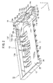
- Fig. 1 is an exploded, perspective view showing a card socket of an embodiment of the present invention;
- Fig. 2 is a perspective view of the insulator of Fig. 1;
- Fig. 3 is a partial, enlarged view of the insulator of Fig. 2;
- Fig. 4 is a partial, enlarged view of another part of the insulator of Fig. 2;
- Fig. 5 is a perspective view of the slider of Fig. 1;
- Fig. 6 is a perspective view of the slider of Fig. 1, as seen in the opposite direction of Fig. 5;
- Fig. 7 is a perspective view of the rocker arm of Fig. 1;
- Fig. 8 is a perspective view of the button of Fig. 1;
- Fig. 9 is a perspective view of the button of Fig. 1, as seen in a direction different from that of Fig. 8.
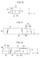
- Fig. 10 is a front view of the button shown in Fig. 8;
- Fig. 11 is a side view of the button shown in Fig. 8;
- Fig. 12 is the other side view of the button shown in Fig. 8;
- Fig. 13 is a plan view of the button shown in Fig. 8;
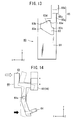
- Fig. 14 is a schematic view of relationship between the slider and the rocker arm in the card socket;
- Fig. 15 is a perspective view of the card socket under the initial state of the card insertion process;
- Fig. 16 is a parcially cross-sectional view which is associated with the state shown in Fig. 15;
- Fig. 17 is a bottom view of some components of the card socket in the state shown in Fig. 15;
- Fig. 18 is a perspective view of the card socket in a state where the card is completely inserted into the card socket;
- Fig. 19 is a partially cross-sectional view which is associated with the state shown in Fig. 18;
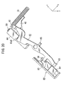
- Fig. 20 is a bottom view of some components of the card socket in the state shown in Fig. 18;
- Fig. 21 is a view which shows relation of a pressed portion of the button and the overhanging portion of the case;
- Fig. 22 is a perspective view of the card socket, which is in a state associated with a long card; and
- Fig. 23 is a bottom view of the card socket in the state shown in Fig. 22 and shows relation of main parts.
- Referring to Figs. 1 to 23, a card socket according to an embodiment of the present invention is described in detail below.
- As shown in Fig. 1, the
card socket 100 according to the present embodiment of the present invention comprises acase 30, aslider 40, afirst compression spring 50, arocker arm 60, asecond compression spring 70 and abutton 80. - The
case 30 comprises aninsulator 10 and acover 20. Theinsulator 10 comprises anedge 10a, aportion 10b, and abottom portion 11. Theedge 10a constitutes a rear end of theinsulator 10 in a Y-direction. Theportion 10b further projects outwardly of theinsulator 10 in comparison with theedge 10a. Thecover 20 comprises anedge 20a and aportion 20b. Theedge 20a constitutes a rear end of thecover 20 in the Y-direction. Theportion 20b further projects outwardly of thecover 20 in comparison with theedge 20a. Thebottom portion 11 and thecover 20 define acard housing space 32, which can accommodate a card. Theedge 10a and theedge 20a define anopen end 34. Theopen end 34 has a rectangular shape, which is long in an X-direction and is short in a Z-direction. With reference to Fig. 15, theopen end 34 allows acard 200 to be inserted into thecard housing space 32 and to be ejected from thecard housing space 32 along the Y-direction. Turning back to Fig. 1, theinsulator 10 holds a plurality ofterminals 36, while a free end of the eachterminal 36 projects inwardly of thecard housing space 32 in the Z-direction so that the eachterminal 36 has resilience. Thecard 200 is pressed on thecover 20 by theterminals 36 when thecard 200 is inserted into thecard housing space 32. - As shown in Fig. 2, the
insulator 10 comprises afirst wall 12, asecond wall 13 and athird wall 14. The first to thethird walls 12 to 14 surround three sides of thebottom portion 11. Thebottom portion 11 comprises afirst bottom portion 11a and asecond bottom portion 11b. Thefirst bottom portion 11a constitutes the bottom surface of thecard housing space 32. Thesecond bottom portion 11b is concaved by a predetermined depth in comparison with thefirst bottom portion 11 a. In this embodiment, the predetermined depth is equal to the thickness of therocker arm 60 in the Z-direction. As described later, thesecond bottom portion 11b rockably accommodates therocker arm 60. Thesecond bottom portion 11b is formed with apivot 11c. Thepivot 11c is positioned nearly at the center of thesecond bottom portion 11b in the Y-direction. Thepivot 11c projects in the Z-direction and has a short cylindrical shape. Thepivot 11c constitutes a fulcrum of rocking movement of therocker arm 60, as described later. Thebottom portion 11 of theinsulator 10 is formed with athrough hole 11d, which has a staircase-like shape of a single step. The position of the throughhole 11d is the border between thefirst bottom portion 11a and thesecond bottom portion 11b and around thepivot 11c. - As apparent from Figs. 1 to 3, the
second wall 13 is placed at the farthest region from theopen end 34 in the Y-direction. Thesecond wall 13 comprises athick wall 13a, athin wall 13b and aguide rail 13c. Thethick wall 13a is thicker than thethin wall 13b. Theguide rail 13c is located far from thethin wall 13b by a predetermined distance. Theguide rail 13c projects from thesecond bottom portion 11b in the Z-direction. Thethin wall 13b and theguide rail 13c extend from thethick wall 13a along the X-direction. Thethin wall 13b and theguide rail 13c define aspring accommodation ditch 13d therebetween. From thespring accommodation ditch 13d, aspring accommodation hole 13e extends into thethick wall 13a along the X-direction. Thespring accommodation ditch 13d and thespring accommodation hole 13e form aspring accommodation portion 13f. Thespring accommodation portion 13 f accommodates thesecond compression spring 70. - As shown in Figs. 2 to 4, the
third wall 14 comprises afirst portion 14a, asecond portion 14b, athird portion 14c, agroove portion 14d, and afourth portion 14e. Thefirst portion 14a extends from thesecond wall 13 in the Y-direction. Thesecond portion 14b is thicker than thefirst portion 14a in the X-direction. Thethird portion 14c is lower than thesecond portion 14b in the Z-direction. Thegroove portion 14d is formed in thethird portion 14c and extends in the Y-direction. The depth direction of thegroove portion 14d is the Z-direction. Thefourth portion 14e extends from thethird portion 14c along the Y-direction. As best shown in Fig. 4, an inner surface of thefourth portion 14e and an inner surface of thegroove portion 14d are in line with each other, as seen from the Z-direction. - As shown in Figs. 2 and 4, the
second bottom portion 11b is provided with anisland portion 15. Thepivot 11c is placed between thecard housing space 32 and theisland portion 15 in the X-direction. The illustratedisland portion 15 is placed on the rear half of theinsulator 10 in the Y-direction. Theisland portion 15 has the same height as that of thepivot 11c. Theisland portion 15 is provided with a standingwall 15a, anedge portion 15b, aplateau portion 15c and aportion 15d. The standingwall 15a is placed at the nearest position to thepivot 11 c on theisland portion 15 and extends along the Y-direction. As described later, the standingwall 15a and thesecond portion 14b form a guide portion for receiving a rear portion of theslider 40. Theedge portion 15b constitutes the front end of theisland portion 15 and defines an end position of theslider 40. Theplateau portion 15c is placed on an end portion of theisland portion 15 in the Y-direction and protrudes in the Z-direction. Theplateau portion 15c has the same height as that of thethird portion 14c of thethird wall 14. Theportion 15d constitutes a side surface of theisland portion 15, which is positioned near theplateau portion 15c. Theportion 15d is perpendicular to the X-Y plane and extends diagonally across the X- and the Y-directions. - As also shown in Figs. 2 and 4, the
insulator 10 is further provided with afirst projection portion 16. Thefirst projection portion 16 is formed on thesecond bottom portion 11b and is positioned away from theisland portion 15 in the Y-direction. Thefirst projection portion 16 has an L-shaped cross-section in the X-Z plane. Thefirst projection portion 16 projects from thesecond bottom portion 11b in the Z-direction and then projects in the X-direction. Thefirst projection portion 16 and thesecond bottom portion 11b form agap 16a therebetween. Thegap 16a accommodates a part of therocker arm 60, as described later. Thegap 16a described in this embodiment is slightly larger than the thickness of therocker arm 60. Thefirst projection portion 16 is provided with aportion 16b. Theportion 16b is perpendicular to thesecond bottom portion 11b and faces thegap 16a. As shown in Fig.4, theportion 16b and theportion 15d are substantially in line with each other. - As best shown in Fig. 4, the
first projection portion 16 is positioned with a predetermined distance left between thefourth portion 14e of thethird wall 14 and thefirst projection portion 16. The predetermined distance is the same as the width of thegroove portion 14d in the X-direction. Thefirst projection portion 16 and theisland portion 15 define afirst region 11e therebetween. The role of thefirst region 11e will be described with therocker arm 60. - As shown in Figs. 2 and 4, the
insulator 10 further comprises asecond projection portion 17. Thesecond projection portion 17 is placed away from thefirst projection portion 16 in the Y-direction. Thefirst projection portion 16 is placed between theisland portion 15 and thesecond projection portion 17. Thesecond projection portion 17 projects from thebottom portion 11 in the Z-direction. Thesecond projection portion 17 is placed with the predetermined distance left between thefourth portion 14e of thethird wall 14 and thesecond projection portion 17. Thesecond projection portion 17 and the first projection portion 16d define asecond region 11f therebetween. The role of the second region 1f will be described with therocker arm 60. As shown in Fig.1, thesecond projection potion 17 is positioned on theportion 10b. Theportion 10b and theportion 20b form an overhangingportion 38. The overhangingportion 38 sticks out from theopen end 34 in the Y-direction. The function of the overhangingportion 38 will be described with a press operation of thebutton 80. - As shown in Fig. 1, the
cover 20 comprises acantilever spring 22 and aguide plate 24. Thecantilever spring 22 is arranged to face thegroove portion 14d of theinsulator 10. Thecantilever spring 22 extends inwardly of thecase 30 and in the direction of the insertion of the card. Thecantilever spring 22 urges thebutton 80 to project from thecase 30 in the Y-direction. Theguide plate 24 is flat and extends from thecover 20 inwardly of thecase 30 in the Z-direction and also extends in the Y-direction. Theguide plate 24 is obtainable by making an angular U-shaped cut into the main surface of thecover 20 to form a plate portion, followed by bending the plate portion inwardly of thecase 30. - As shown in Figs. 5 and 6, the
slider 40 comprises amain portion 41 and atransmission portion 42. Themain portion 41 has a rectangular parallelepiped shape which is long in the Y-direction. Thetransmission portion 42 projects from themain portion 41 in the X-direction. Theslider 40 is provided with a guidedslit portion 43, which is formed between themain portion 41 and thetransmission portion 42. The guidedslit portion 43 receives theguide plate 24 of thecover 20. From the bottom of themain portion 41, aprojection portion 44 projects in the Z-direction. Theprojection portion 44 has a rectangular cross-section in the X-Y plane. Theprojection portion 44 is slidable on thesecond bottom portion 11b. In this embodiment, a projection amount of theprojection portion 44 is as much as the thickness of therocker arm 60. - The
main portion 41 of theslider 40 is provided with a guidedportion 45, which constitutes the rear end portion of themain portion 41. In themain portion 41, the guidedportion 45 is narrower than the other part. The guidedportion 45 hasshoulder portions portion 45 is accommodated in the guide portion defined by the standingwall 15a of theisland portion 15 and thesecond portion 14b of thethird wall 14. The guide portion, theguide plate 24 of thecover 20 and the guidedslit portion 43 of theslider 40 prevents theslider 40 from moving in the X-direction even if theslider 40 receives a force in the X-direction. - When the
shoulders slider 40 are brought into contact with the standingwall 15a and thesecond portion 14b, theprojection portion 44 of theslider 40 is brought into contact with theedge portion 15b of theisland portion 15 and is prevented from further sliding. In this embodiment, a position of theslider 40 is referred to as a first position, at which theslider 40 is positioned when thecard 200 is completely inserted into thecase 30. Another position of theslider 40 is referred to as a second position, at which theslider 40 is prevented from sliding backward in the Y-direction by theisland portion 15 and so on. - As shown in Fig. 6, the
slider 40 is provided with ahole 48. Thehole 48 is formed in themain portion 41 and extends in the Y-direction. Thehole 48 receives thefirst compression spring 50 therein. Thefirst compression spring 50 is mounted on theinsulator 10 together with theslider 40 and urges theslider 40 to move toward the second position. - In this embodiment, the
transmission portion 42 of theslider 40 is placed above thespring accommodation portion 13 f of theinsulator 10 in the Z-direction, as understood from Figs. 18 and 20, when thecard 200 is inserted into thecase 30 and theslider 40 is positioned at the first position. In this event, thetransmission portion 42 is not in contact with theguide rail 13c and thesecond compression spring 70. Thus, the projection area of thecard socket 100 is downsized. - As shown in Fig. 7 the
rocker arm 60 comprises amain plate 61. Themain plate 61 comprises afirst end portion 61b and asecond end portion 61 c. Themain plate 61 is formed with apivot opening 61a, which is positioned between thefirst end portion 61b and thesecond end portion 61 c. Thefirst end portion 61a is formed with a first pressedportion 62, which has a U-shaped cross-section. The bottom of the U-shape of the first pressedportion 62 projects upwards in the Z-direction. Thesecond end portion 61 c of themain plate 61 is formed with a posterioredge receiving portion 63. The posterioredge receiving portion 63 projects from thesecond end portion 61c in the Z-direction. As shown in Fig. 18, when thecard 200 of a predetermined size is inserted into thecard housing space 32, the posterioredge receiving portion 63 receives the posterior edge of thecard 200 and prevents thecard 200 from falling out of thecard housing space 32. Turning back to Fig. 7, therocker arm 60 is further provided with a second pressedportion 64, which is positioned between thepivot opening 61a and thesecond end portion 61c and projects in the Z-direction. - In detail, the
main plate 61 comprises afirst plate portion 61d, asecond plate portion 61e and athird plate portion 61f. Thefirst plate portion 61d comprises a narrow plate portion 61d3 and a wide plate portion 61d4. The narrow plate portion 61d3 is placed between thepivot opening 61a and the wide plate portion 61d4. The wide plate portion 61d4 is placed between the narrow plate portion 6 1 d3 and thesecond plate portion 61e. Thesecond plate portion 61e has an L-like shape. The front edge of thefirst plate portion 61d is slightly carved. As described later, the front edge of thefirst plate portion 61d receives theprojection portion 44 of theslider 40 in the Y-direction when theslider 40 is positioned at the first position. Thus, the front edge of thefirst plate portion 61d serves as a stopper 61d1 which prevents theslider 40 from sliding toward the second position. Thethird plate portion 61f extends from thefirst plate portion 61d with thepivot opening 61a positioned therebetween. In this embodiment, thefirst plate portion 61d and thethird plate portion 61f are not arranged on a straight line. Thefirst plate portion 61d and thesecond plate portion 61e form a dogleg shape. Themain plate 61 comprises arestriction portion 65. Therestriction portion 65 is placed near thepivot opening 61a and projects in the Z-direction. In detail, therestriction portion 65 projects opposite to the projecting direction of the first and the second pressedportions edge receiving portion 63. - As shown in Fig. 1, the
pivot 11c is rotatably fitted into thepivot opening 61a so that therocker arm 60 is held on thesecond bottom portion 11b of theinsulator 10. Therestriction portion 65 is accommodated in the throughhole 11d of theinsulator 10. Therestriction portion 65 restricts the rocking movement of therocker arm 60 and allows themain plate 61 to rock in a plane parallel to the second bottom portion 1b of theinsulator 10, i.e., the X-Y plane. The rockable range of therocker arm 60 is defined by and thefirst plate portion 61d and thethird plate portion 61f the step height between thefirst bottom portion 11a and thesecond bottom portion 11b. In this embodiment, when thethird plate portion 61f of therocker arm 60 is brought into contact with thefirst bottom portion 11a in the X-direction as shown in Fig.19, therocker arm 60 is placed at a first rock position. When thefirst plate portion 61d of therocker arm 60 is brought into contact with thefirst bottom portion 11a in the X-direction, as shown in Fig. 16, therocker arm 60 is placed at a second rock position. - With reference to Figs. 1 and 15, the first pressed
portion 62 of therocker arm 60 is arranged to straddle theguide rail 13c of theinsulator 10 to be brought into contact with thesecond compression spring 70 in the X-direction. The first pressedportion 62 receives a force from thesecond compression spring 70 to move toward theslider 40. Thesecond compression spring 70 constitutes, in cooperation with thespring accommodation portion 13f, asecond urging portion 71 and urges therocker arm 60 to move toward the first rock position. As apparent from Figs. 1, 2 and 4, the second pressedportion 64 is movable in thefirst region 11e, and the posterioredge receiving portion 63 is movable in thesecond region 11f. Because thefirst region 11e, thesecond region 11f and thegap 16a is provided for theinsulator 10, the second pressedportion 64 and the posterioredge receiving portion 63 can move smoothly during the rock movement of therocker arm 60 between the first rock position and the second rock position. - As shown in Fig. 16, in the state where the
rocker arm 60 is positioned at the second rock position, thefirst plate portion 61 d of therocker arm 60 extends toward thesecond wall 13 along the Y-direction. In this state, the edge portion 6 1 d2 of the wide plate portion 6 1 d4 projects toward thethird wall 14. Thesecond plate portion 61e extends from the end portion of thefirst plate portion 61d in the X-direction away from theslider 40 and then extends toward thesecond wall 13 in the Y-direction. - As shown in Fig. 19, in the state where the
rocker arm 60 is positioned at the first rock position, thethird plate portion 61 f extends toward theopen end 34 along the Y-direction. - Under the positional relation described above, the
rocker arm 60 and theslider 40 move as shown in Fig. 14. In Fig. 14, theslider 40 at the first position is shown by the dashed line. Theslider 40 at the second position is shown by the solid line. Therocker arm 60 at the first rock position is shown by the dashed line. Therocker arm 60 at the second rock position is shown by the solid line. - As shown in Fig. 14, the
rocker arm 60 receives from the second compression spring 70a a force which is shown by the outlined arrow, wherein the force is hereinafter referred to as a first force. When theslider 40 is placed at the second position, therocker arm 60 is prevented from rocking toward the first rock position by theprojection portion 44 of theslider 40. When theslider 40 slides to the first position upon the insertion of the card, therocker arm 60 is allowed to rock toward the first rock position from the second rock position. Therocker arm 60 at the first rock position prevents theslider 40 from sliding to the second position. In this state, when a force shown by the black arrow is applied to the second pressedportion 64, therocker arm 60 is moved toward the second rock position, wherein the force of the black arrow is hereinafter referred to as a second force. Then, nothing blocks the movements of theslider 40 so that theslider 40 slides to the second position in accordance with thefirst compression spring 50. The movement of theslider 40 in the Y-direction is transmitted to the card by means of thetransmission portion 42 so that the card is ejected from thecard socket 100. - In the above-mentioned movement, the
button 80 serves as a portion for providing the second force to the second pressedportion 64 of therocker arm 60. As shown in Figs. 8 to 13, thebutton 80 comprises amain portion 81 and a pressedportion 82. Themain portion 81 is a rectangular plate. The pressedportion 82 is formed at the rear end of themain position 81. As shown in Fig. 18, the pressedportion 82 projects out from thecase 30 along the Y-direction, when the card is completely inserted into thecase 30. The projecting direction of the pressedportion 82 is referred to as a card ejection direction. The pressedportion 82 is pressed by a user for ejecting the inserted card from thecase 30 in the card ejection direction. - As shown in Figs. 15, 18 and 22, the
button 80, especially themain portion 81, and themain portion 41 of theslider 40 are arranged on an imaginal straight line in the Y-direction. As apparent from Fig. 15 or 18, the imaginal straight line is laid on the outside region of thecard housing space 32 in the X-direction so that thecard 200 is not in contact with thebutton 80 and themain portion 41 of theslider 40 upon the insertion or the ejection of thecard 200. As apparent from Fig. 16 or 19, the pivot opening 61 a of therocker arm 60 and thepivot 11c of theinsulator 10 are placed away from the imaginal straight line in the X-direction. Especially, in this embodiment, the pivot opening 61 a of therocker arm 60 and thepivot 11c of theinsulator 10 are placed inwardly of thecase 30 in the X-direction, as seen from the imaginal straight line. - With reference to Figs. 8 to 13, the
main portion 81 of thebutton 80 is formed with anaccommodation portion 83. Theaccommodation portion 83 accommodates the second pressedportion 64 of therocker arm 60. In this embodiment, theaccommodation portion 83 is a through-hole in the Z-direction. Thebutton 80 is further formed with aspace 84, which is positioned between theaccommodation portion 83 and the pressedportion 82, as shown in Fig. 12. Thespace 84 accommodates the posterioredge receiving portion 63 of therocker arm 60 when therocker arm 60 is positioned at the second rock position. Thelower surface 81a of themain portion 81 is lower than theupper surface 84a of thespace 84 in the Z-direction. Thelower surface 81a of themain portion 81 and the upper surface of theplateau portion 15c are placed on the same level in the Z-direction when thebutton 80 is mounted on theinsulator 10. Theupper surface 84a of thespace 84 and the upper surface of thefirst projection portion 16 are placed on the same level in the Z-direction when thebutton 80 is mounted on theinsulator 10. - The pressed
portion 82 is formed with a projection-accommodation portion 82a. The projection-accommodation portion 82a accommodates thesecond projection portion 17 of theinsulator 10 when thebutton 80 is pressed into thecase 30 in the Y-direction. When the projection-accommodation portion 82a accommodates thesecond projection portion 17, thebutton 80 is prevented from being further pressed into thecase 30 in the Y-direction. Thus, thesecond projection portion 17 prevents the forward movement of thebutton 80 over thesecond projection portion 17 in the Y-direction. - From the front end of the
main portion 81 of thebutton 80, aprojection head 85 projects in the Y-direction, as shown in Figs. 8 and 9. As shown in Figs. 11 and 12, theprojection head 85 comprises afirst portion 85a and asecond portion 85b. Thefirst portion 85a has a rectangle-like shape and projects from themain portion 81 in the Y-direction. Thesecond portion 85b further projects from thefirst portion 85a forward in the Y-direction. Thesecond portion 85b has a curved surface, which extends in the Y-direction and curves downwards in the Z-direction. When thebutton 80 is mounted on thecard socket 100, thecantilever spring 22 presses thesecond portion 85b backward in the Y-direction. That is, thecantilever spring 22 formed in thecover 20 urges thebutton 80 to project outwardly of thecase 30. As most clearly shown in Fig. 13, thesecond portion 85b projects outwardly in the X-direction in comparison with thefirst portion 85a. On the border between thefirst portion 85a and thesecond portion 85b, ashoulder portion 85c is formed. When thebutton 80 is moved backward in the Y-direction, thefourth portion 14e receives theshoulder portion 85c and stops the further movement of thebutton 80. Thus, theshoulder portion 85c and thefourth portion 14e define an amount of the projection of thebutton 80 from thecase 30. - As shown in Figs. 9 to 12, the
button 80 is provided with a guidedrail 86. The guidedrail 86 extends downwardly from the outer edge of themain portion 81 and theprojection head 85 in the Z-direction. The guidedrail 86 is inserted in thegroove portion 14d so that the guidedrail 86 is slidable in the Y-direction. Thebutton 80 is held on theinsulator 10 to be slidable in the Y-direction. Between thefirst projection portion 16 and thefourth portion 14e and between thesecond projection portion 17 and thefourth portion 14e, there are the gaps, each of which has the same width as thegroove portion 14d. The guidedrail 86 is prevented from moving in the X-direction by thefirst projection portion 16, thesecond projection portion 17 and thefourth portion 14e of thethird wall 14 so that thebutton 80 can move properly along the Y-direction. - With reference to Fig. 9, 10 and 12, the
main portion 81 is provided with awall 87. Thewall 87 extends from the inner edge of themain portion 81 in the Z-direction and is opposite to the guidedrail 86 in the X-direction. When thegroove portion 14d guides the guidedrail 86 so that thebutton 80 slides in the X-direction, thewall 87 slides on the upper surface of theisland portion 15 and on the side surface of theplateau portion 15c. Because thebutton 80 is formed so that theupper surface 84a of thespace 84 is slidable on the upper surface of thefirst projection portion 16, the movement of thebutton 80 in the Z-direction is properly regulated. - As most clearly shown in Fig. 13, the backward surface in the Y-direction of the
accommodation portion 83 constitutes acam surface 83a. Thecam surface 83a is formed perpendicular to the X-Y plane and across the X-Z plane as well as the Y-Z plane. Theaccommodation portion 83 is further formed with afirst receiving portion 83b and asecond receiving portion 83c, which correspond to the opposite ends in the Y-direction of thecam surface 83a and are faced to thecam surface 83a in the X-direction. Thefirst receiving portion 83b receives the second pressedportion 64 in the Y-direction when therocker arm 60 is positioned at the first rock position. Thesecond receiving portion 83c receives the second pressedportion 64 in the Y-direction when therocker arm 60 is positioned at the second rock position. In this embodiment, thebutton 80 is further provided with apocket 83d. Thepocket 83d is necessary when a long card longer than the predetermined length is used. The operations in the state where the long card is inserted into thecard socket 100 will be described later. - Here, a supplemental description of the operations or the movements of the button are made. In the state of the complete insertion of a card, the
button 80 is pressed by thecantilever spring 22 toward the card election direction to project outwardly of thecase 30. When thebutton 80 is pressed inwardly of thecard 30 or toward thesecond wall 13 along the Y-direction against the elastic force of thecantilever spring 22, the second pressedportion 64 is apart from the first receivingportion 83b and is brought into contact with thecam surface 83a. When thebutton 80 is further pressed along the card insertion direction, the second pressedportion 64 is guided by thecam surface 83a and is moved outwards in the X-direction. In other words, thecam surface 83a converts the insertion force toward the Y-direction into the second force toward the X-direction and transmits the second force to thesecond press portion 64. By the function of thecam surface 83a, therocker arm 60 moves from the first rock position toward the second rock position upon the card ejection. When thebutton 80 is released upon the card ejection, thebutton 80 is slightly slid by thecantilever spring 22 toward the card ejection direction so that the second pressedportion 64 is received by thesecond receiving portion 83c. - Next explanation will be made about the whole operations of the
card socket 100 with reference to Figs. 14 to 20. - As shown in Figs. 15 to 17, prior to the insertion of the
card 200, theslider 40 is positioned at the second position and is pressed by thefirst compression spring 50 toward the card ejection direction. In this state, theprojection portion 44 receives the edge portion 61d2 in the X-direction so that therocker arm 60 is prevented from rocking toward the first rock position even if therocker arm 60 receives the first force from thesecond compression spring 70. In this state, the second pressedportion 64 is received on thesecond receiving portion 83c of theaccommodation portion 83. - When the
card 200 is inserted into thecard housing space 32, thetransmission portion 42 receives a force due to the insertion of thecard 200 so that theslider 40 slides toward the first position. In this event, theprojection portion 44 is also moved forward in the Y-direction and releases theedge 61 d2. Because thesecond compression spring 70 always provides the first force to the first pressedportion 62, the releasedrocker arm 60 rotates around thepivot 11c so that therocker arm 60 is positioned at the first rock position and the stopper portion 61d1 receives the rear end of theprojection portion 44 in the Y-direction, as shown in Fig. 18 to 20. Theslider 40 is urged by thefirst compression spring 50 to slide toward the second position. Thus, after the complete insertion of thecard 200, theslider 40 is prevented from sliding to the second position by the stopper portion 61d1. - The
button 80 is pressed backwards in the Y-direction by thecantilever spring 22 so that the second pressedportion 64 is pressed against thefirst receiving portion 83d, as shown in Fig. 18. - As also shown in Fig. 18, the posterior
edge receiving portion 63 is located behind theposterior end 210 of thecard 200 so that thecard 200 is prevented from undesirably falling out of thecard socket 100. As apparent from the above description, card ejection is not carried out unless thebutton 80 is pressed inwards. For example, therocker arm 60 does not rock toward the second position even if thecard socket 100 receives some shock. Therefore, the malfunction of the card ejection mechanism does not occur according to the present embodiment. In addition, because the above-mentioned operations are carried out in accordance with the insertion of thecard 200, there is no complex operation and the operationality is good. Thepivot 11c and thepivot portion 61a are placed between the first and the second pressedportions rocker arm 60, so that the high reliability and the high operationality described above can be obtained without making the projection area of thecard socket 100 large. - As shown in Fig. 21, when the pressed
portion 82 of thebutton 80 is pressed inward of thecard socket 100 or forward in the Y-direction, the second pressedportion 64 receives the second force so that therocker arm 60 is moved toward the second rock position. In this event, the stopper 61d1 releases theprojection portion 44 so that theslider 40 is moved toward the second position by thefirst compression spring 50. The movement of theslider 40 is transmitted to thecard 200 through thetransmission portion 42 so that thecard 200 is ejected from thecard socket 100. As apparent from Fig. 21, because thecase 30 according to this embodiment comprises the overhangingportion 38, theposterior end 210 of thecard 200 does not directly pressed, even when thebutton 80 is pressed. Therefore, thecard 200 is protected from erroneous insertion. Furthermore, when thebutton 80 is pressed to eject thecard 200, thecard 200 comes into contact with a finger of a user. Therefore, the problem of unexpected jump of thecard 200 is avoidable. - In this embodiment, the
rocker arm 60 has a third rock position. The third rock position is a rock position between the first and the second rock positions. As shown in Figs. 22 and 23, when therocker arm 60 is positioned at the third rock position, the posterioredge receiving portion 63 is located within thespace 84, while the stopper portion 61d1 receives theprojection portion 44 in the Y-direction. The angle between thefirst plate portion 61d and thethird plate portion 61f of therocker arm 60 and the projection amount of the edge portion 61d2 or the lateral length of the stopper portion 61d1 are selected to allow therocker arm 60 to take the third rock position. - Because the
rocker arm 60 takes the third rock position, thecard socket 100 can accept two types of cards whose lengths in the Y-direction are different from each other. When thesmall card 200 of the predetermined length is inserted as shown in Figs. 18 and 19, theslider 40 is positioned at the first position, and therocker arm 60 is positioned at the first rock position. On the other hand, when the long card longer than the predetermined length is inserted, theslider 40 is also pressed toward the first rock position, and therocker arm 60 is rotated by the first force of thesecond compression spring 70, as shown in Figs. 22 and 23. However, the posterioredge receiving portion 63 is brought into contact with the side portion of the long card so that the rotation of therocker arm 60 is stopped. Thus, therocker arm 60 does not reach the first rock position and stays at the third position. - When the long card is inserted, the second pressed
portion 64 leaves thesecond receiving portion 83c and moves toward the first receivingportion 83b as well as the insertion of the small card. However, the movement of the second pressedportion 64 is stopped before the second pressed portion reaching to the first receivingportion 83b. In this embodiment, thepocket portion 83d is formed in theaccommodation portion 83, so that the stopped second pressedportion 64 is received on athird receiving portion 83e of thepocket portion 83d. Thebutton 80 can projects outwardly from thecase 30. - In this embodiment, the
cantilever spring 22 of thecaver 20 is an example of the urging portion which urges thebutton 80 to move toward in the card ejection direction. This urging portion is not limited to thecantilever spring 22, but may be another structure which can urge thebutton 80 to move toward the card ejection direction.
Claims (10)
- A card socket (100) comprising:a case (30) which is holdable a card and allows insertion/ejection of the card thereinto/therefrom;a slider (40) which is slidably held in the case (30) and is provided with a transmission portion (42) for mutually transmitting movements of the card and the slider (40) therebetween, wherein the slider (40) is slidable between a first position and a second position, and the slider (40) slides with the card toward the first position upon the insertion, while the slider (40) slides with the card toward the second position upon the ejection;first urging means (50) which urges the slider (40) to move toward the second position;a rocker arm (60) which is provided with a fulcrum (61a), first and second pressed portions (62; 64) and a stopper (61d1), wherein the fulcrum (61a) is held in the case (30) in a condition where the rocker arm (60) is rockable between a first rock position and a second rock position, wherein the rocker arm (60) is positioned at the first rock position when the slider (40) is positioned at the first position, wherein the rocker arm (60) is positioned at the second rock position when the slider (40) is positioned at the second position, wherein the fulcrum (61a) is positioned between the first and the second pressed portions (62; 64), wherein the stopper is located between the first pressed portion (62) and the fulcrum (61a), and wherein the stopper (61d1) receives the slider (40) positioned at the first position when the rocker arm (60) is positioned at the first rock position;second urging means (71) which provides a first force for the first pressed portion (62) to urge the rocker arm (60) to move toward the first rock position; andan operation member (80) which is movably held by the case (30) and is for providing a second force for the second pressed portion (64) to urge the rocker arm (60) to move toward the second rock position against the first force.
- A card socket (100) according to claim 1, wherein:the case (30) is provided with a card housing space (32) and an open end (34), wherein the open end (34) allows the card to be inserted into the card housing space (32) and allows the card to be ejected from the card housing space (32) along a first direction;the open end (34) has a rectangle shape, which is long in a second direction orthogonal to the first direction and is short in a third direction orthogonal to the first and the second directions;the slider (40) is slidable along the first direction; andthe second urging means (71) is placed farther from the open end (34) than the card housing space (32) and provides the first force along the second direction.
- A card socket (100) according to claim 1 or 2, wherein:the rocker arm (60) comprises a main plate (61), the first pressed portion (62) and the second pressed portion (64);the main plate (61) is provided with first and second end portions (61b; 61c) and the fulcrum (61a);the fulcrum (61a) is positioned between the first and the second end portions (61b; 61c);the first pressed portion (62) is positioned at the first end portion (61b);the second pressed portion (64) is positioned between the fulcrum (61a) and the second end portion (61c); andthe main plate (61) is laid on a plane defined by the first and the second directions.
- A card socket (100) according to one of claims 1 to 3, wherein:the second urging means (71) comprises a compression spring (70);the case (30) comprises a guide rail (13c) and a wall (13), wherein the guide rail (13c) extends in the second direction at a specific region which is farther from the open end (34) in the first direction than the card housing space (32), and the wall (13) extends in the second and the third directions and is located far from the guide rail (13c) by a predetermined distance;the guide rail (13c) and the wall (13) of the case (30) define a spring accommodation portion (13f) which accommodates the compression spring (70) of the second urging means (71); andthe first pressed portion (62) is provided with a U-shaped portion, which projects from the first end portion (61b) in the third direction and is arranged to straddle the guide rail (13c) to be brought into contact with the compression spring (70) of the second urging means (71) in the second direction.
- A card socket (100) according to claim 3 or 4, wherein:the main plate (61) of the rocker arm (60) comprises a first plate portion (61d), a second plate portion (61e) and a third plate portion (61f);the first plate portion (61d) extends from the fulcrum (61a) toward the wall (13) and is provided with a narrow plate portion (61d3) and a wide plate portion (61d4);the narrow plate portion (61d3) is connected between the fulcrum (61a) and the wide plate portion (6 1 d4);the wide plate portion (61d4) projects toward the second position of the slider (40);the second plate portion (61e) has an L-shaped portion, which extends from the wide plate portion (61 d4) of the first plate portion (61d) away from the slider (40) and then extends toward the wall (13);the first pressed portion (62) is formed at a free end of the second plate portion (61e);the third plate portion (61f) is connected to the first plate portion (61d); andthe fulcrum (61a) is positioned between the first and the third plate portions (61d; 61f).
- A card socket (100) according to claim 5, wherein:the slider (40) comprises a projection portion (44), which projects in the third direction;the wide plate portion (61d4) receives the projection portion (44) in the first direction when the rocker arm (60) is positioned at the first rock position, wherein the wide plate portion (61d4) serves as the stopper (61d1); andthe projection portion (44) is brought into contact with the wide plate portion (61d4) in the second direction to prevent the rocker arm (60) from moving toward the first rock position when the rocker arm (60) is positioned at the second rock position.
- A card socket (100) according to one of claims 2 to 6, wherein:the second pressed portion (64) of the rocker arm (60) projects in the third direction;the operation member (80) is held by the case (30) and is movable in the first direction;the operation member (80) is provided with an accommodation opening (83) which accommodates the second pressed portion (64); andthe accommodation opening (83) is provided with a cam surface (83a) which translates motion of the operation member (80) into the second force.
- A card socket (100) according to claim 7, wherein:the operation member (80) is a button which outwardly projects from the case (30) in the first direction in a state of the insertion and which is movable inwardly of the case (30) by being pushed along the first direction; andthe cam surface (83a) translates the inward movement of the operation member (80), and preferably, wherein:the case (30) comprises a overhanging portion (38) which sticks out from the open end (34) in the first direction; andthe operation member (80) projects from the overhanging portion (38) in the first direction in the state of the insertion.
- A card socket (100) according to claim 7, wherein:the slider (40) is further provided with a main portion (41);the main portion (41) extends in the first direction;the transmission portion (42) extends from the main portion (41) in the second direction; andthe main portion (41) of the slider (40) and the operation member (80) are arranged on an imaginal straight line which extends along the first direction, and preferably, wherein:the main portion (41) and the operation member (80) are arranged outside the card housing space (32) in the second direction; and/orthe fulcrum (61a) of the rocker arm (60) is away from the imaginal straight line in the second direction.
- A card socket (100) according to one of claims 2 to 9, wherein:the rocker arm (60) is provided with a posterior edge receiving portion (63);the posterior edge receiving portion (63) is for receiving a posterior edge of a particular card which has a predetermined size and is completely insertable in the card holding space (32); andthe posterior edge receiving portion (63) is positioned between the open end (34) and the second pressed portion (62) and projects toward the third direction, and preferably, wherein:the rocker arm (60) is positionable at a third rock position between the first and the second rock positions when a long card is inserted, which is longer in the first direction than the particular card;the stopper (61d1) is holdable the slider (40) in the first position even when the rocker arm (60) is positioned at the third rock position; andthe posterior edge receiving portion (63) is located outside the card housing space (32) in the first direction, when the rocker arm (60) is positioned at the third rock position.
Applications Claiming Priority (1)
| Application Number | Priority Date | Filing Date | Title |
|---|---|---|---|
| JP2004214885A JP4028530B2 (en) | 2004-07-22 | 2004-07-22 | Card socket |
Publications (3)
| Publication Number | Publication Date |
|---|---|
| EP1619762A2 true EP1619762A2 (en) | 2006-01-25 |
| EP1619762A3 EP1619762A3 (en) | 2006-05-17 |
| EP1619762B1 EP1619762B1 (en) | 2007-12-26 |
Family
ID=35058630
Family Applications (1)
| Application Number | Title | Priority Date | Filing Date |
|---|---|---|---|
| EP05014673A Expired - Lifetime EP1619762B1 (en) | 2004-07-22 | 2005-07-06 | Card socket |
Country Status (5)
| Country | Link |
|---|---|
| US (1) | US6966786B1 (en) |
| EP (1) | EP1619762B1 (en) |
| JP (1) | JP4028530B2 (en) |
| CN (1) | CN1725573B (en) |
| DE (1) | DE602005003988T2 (en) |
Families Citing this family (20)
| Publication number | Priority date | Publication date | Assignee | Title |
|---|---|---|---|---|
| JP4054022B2 (en) * | 2004-03-18 | 2008-02-27 | 山一電機株式会社 | IC card connector |
| JP3774895B1 (en) * | 2005-02-17 | 2006-05-17 | 日本航空電子工業株式会社 | Card connector |
| CN2831503Y (en) * | 2005-08-15 | 2006-10-25 | 富士康(昆山)电脑接插件有限公司 | Memory card connector |
| JP4585963B2 (en) * | 2005-12-06 | 2010-11-24 | ホシデン株式会社 | Card connector |
| JP2008277194A (en) * | 2007-05-02 | 2008-11-13 | Yamaichi Electronics Co Ltd | Manual feed connector |
| JP4492885B2 (en) * | 2007-10-31 | 2010-06-30 | 日本航空電子工業株式会社 | connector |
| TWI384841B (en) * | 2008-08-27 | 2013-02-01 | Asustek Comp Inc | Mobile communication device and card socket thereof |
| DE102009036101A1 (en) * | 2009-08-04 | 2011-02-24 | Fresenius Medical Care Deutschland Gmbh | Connecting device for connecting at least one external functional device with an arrangement, arrangement comprising such a connecting device and method for connecting |
| KR101659004B1 (en) * | 2009-10-12 | 2016-09-23 | 엘지전자 주식회사 | Portable terminal |
| FR2954571B1 (en) * | 2009-12-21 | 2014-07-11 | Sagem Comm | HOUSING FOR RECEIVING AN EXTRACTIBLE HARD DISK COMPRISING A TILTING CAM TO EXTRACT THIS HARD DISK |
| JP2012195090A (en) * | 2011-03-15 | 2012-10-11 | Tyco Electronics Japan Kk | Card connector |
| JP5432342B1 (en) | 2012-08-24 | 2014-03-05 | タイコエレクトロニクスジャパン合同会社 | Card connector |
| JP5942794B2 (en) * | 2012-11-07 | 2016-06-29 | Smk株式会社 | Push-in / push-eject type card connector |
| JP6079965B2 (en) * | 2013-04-03 | 2017-02-15 | Smk株式会社 | Card connector with removal mechanism |
| US9184537B2 (en) * | 2013-10-25 | 2015-11-10 | J.S.T. Corporation | Self-rejecting connector apparatus and locking method thereof |
| WO2016011605A1 (en) * | 2014-07-23 | 2016-01-28 | 华为技术有限公司 | Digital card connector |
| CN109458385B (en) * | 2017-09-06 | 2024-05-14 | 上海拜骋电器有限公司 | Buckle mechanism and have its positioner |
| US10285291B1 (en) | 2018-02-17 | 2019-05-07 | Cisco Technology, Inc. | Line card ejector with emergency release |
| US10588241B2 (en) | 2018-05-11 | 2020-03-10 | Cisco Technology, Inc. | Cooling fan control in a modular electronic system during online insertion and removal |
| US11212937B2 (en) | 2019-03-21 | 2021-12-28 | Cisco Technology, Inc. | Method and system for preventing or correcting fan reverse rotation during online installation and removal |
Citations (1)
| Publication number | Priority date | Publication date | Assignee | Title |
|---|---|---|---|---|
| JP2001351735A (en) | 2000-06-08 | 2001-12-21 | Hirose Electric Co Ltd | Card connector |
Family Cites Families (9)
| Publication number | Priority date | Publication date | Assignee | Title |
|---|---|---|---|---|
| JPH03297084A (en) * | 1990-04-17 | 1991-12-27 | I T T Canon:Kk | Card connector with ejector |
| CN2244281Y (en) * | 1995-05-12 | 1997-01-01 | 薛湘江 | Automatic ejection IC cassette holder |
| JP3209892B2 (en) * | 1995-09-06 | 2001-09-17 | アルプス電気株式会社 | PC card connector |
| JP3200736B2 (en) | 1999-05-25 | 2001-08-20 | 日本航空電子工業株式会社 | Connector with card lock mechanism |
| TW456606U (en) * | 1999-07-02 | 2001-09-21 | Hon Hai Prec Ind Co Ltd | Card ejecting mechanism of electronic card connector |
| JP3443102B2 (en) * | 2001-03-23 | 2003-09-02 | 山一電機株式会社 | Card connector |
| JP2004055256A (en) * | 2002-07-18 | 2004-02-19 | Tyco Electronics Amp Kk | Connector for cards |
| JP3896078B2 (en) * | 2002-12-26 | 2007-03-22 | 日本航空電子工業株式会社 | Card connector |
| US6790061B1 (en) * | 2003-10-15 | 2004-09-14 | Cheng Uei Precision Industry Co., Ltd. | Two-stage ejection mechanism of card connector |
-
2004
- 2004-07-22 JP JP2004214885A patent/JP4028530B2/en not_active Expired - Fee Related
-
2005
- 2005-06-29 US US11/170,599 patent/US6966786B1/en not_active Expired - Fee Related
- 2005-07-06 EP EP05014673A patent/EP1619762B1/en not_active Expired - Lifetime
- 2005-07-06 DE DE602005003988T patent/DE602005003988T2/en not_active Expired - Lifetime
- 2005-07-22 CN CN200510087428.5A patent/CN1725573B/en not_active Expired - Fee Related
Patent Citations (1)
| Publication number | Priority date | Publication date | Assignee | Title |
|---|---|---|---|---|
| JP2001351735A (en) | 2000-06-08 | 2001-12-21 | Hirose Electric Co Ltd | Card connector |
Also Published As
| Publication number | Publication date |
|---|---|
| JP4028530B2 (en) | 2007-12-26 |
| EP1619762A3 (en) | 2006-05-17 |
| EP1619762B1 (en) | 2007-12-26 |
| JP2006040588A (en) | 2006-02-09 |
| US6966786B1 (en) | 2005-11-22 |
| DE602005003988T2 (en) | 2008-12-18 |
| DE602005003988D1 (en) | 2008-02-07 |
| CN1725573A (en) | 2006-01-25 |
| CN1725573B (en) | 2010-10-06 |
Similar Documents
| Publication | Publication Date | Title |
|---|---|---|
| EP1619762B1 (en) | Card socket | |
| US6394827B2 (en) | Card connector | |
| CN101944669B (en) | Card connector | |
| JP5749589B2 (en) | Card connector | |
| JP2008218045A (en) | Card connector | |
| EP0704939A2 (en) | PC card electrical connector with expandable ejector | |
| JP3950640B2 (en) | Card connector device | |
| JP2014035835A (en) | Connector for card | |
| EP1837953A1 (en) | Card connector | |
| JP4694340B2 (en) | Card connector | |
| KR20090038892A (en) | Connector for Electronic Card | |
| EP1174957B1 (en) | Electrical card connector | |
| JP2006127808A (en) | Connector device for card | |
| JP3902917B2 (en) | Card connector device | |
| JP2007234465A (en) | Card connector | |
| JP3961778B2 (en) | Card connector device | |
| JP3945432B2 (en) | Memory card socket | |
| CN104103959A (en) | Card Plug-in With Taking-out Mechanism | |
| JP2005108764A (en) | Card connector | |
| JP2005108763A (en) | Card connector | |
| JP4676525B2 (en) | Card connector assembly | |
| JPH11219756A (en) | Card connector | |
| CN202564553U (en) | Card connector | |
| JP2005050741A (en) | Card connector | |
| WO2010084814A1 (en) | Connector for card |
Legal Events
| Date | Code | Title | Description |
|---|---|---|---|
| PUAI | Public reference made under article 153(3) epc to a published international application that has entered the european phase |
Free format text: ORIGINAL CODE: 0009012 |
|
| AK | Designated contracting states |
Kind code of ref document: A2 Designated state(s): AT BE BG CH CY CZ DE DK EE ES FI FR GB GR HU IE IS IT LI LT LU LV MC NL PL PT RO SE SI SK TR |
|
| AX | Request for extension of the european patent |
Extension state: AL BA HR MK YU |
|
| PUAL | Search report despatched |
Free format text: ORIGINAL CODE: 0009013 |
|
| AK | Designated contracting states |
Kind code of ref document: A3 Designated state(s): AT BE BG CH CY CZ DE DK EE ES FI FR GB GR HU IE IS IT LI LT LU LV MC NL PL PT RO SE SI SK TR |
|
| AX | Request for extension of the european patent |
Extension state: AL BA HR MK YU |
|
| 17P | Request for examination filed |
Effective date: 20060726 |
|
| 17Q | First examination report despatched |
Effective date: 20060928 |
|
| AKX | Designation fees paid |
Designated state(s): DE GB |
|
| GRAP | Despatch of communication of intention to grant a patent |
Free format text: ORIGINAL CODE: EPIDOSNIGR1 |
|
| GRAS | Grant fee paid |
Free format text: ORIGINAL CODE: EPIDOSNIGR3 |
|
| GRAA | (expected) grant |
Free format text: ORIGINAL CODE: 0009210 |
|
| AK | Designated contracting states |
Kind code of ref document: B1 Designated state(s): DE GB |
|
| REG | Reference to a national code |
Ref country code: GB Ref legal event code: FG4D |
|
| REF | Corresponds to: |
Ref document number: 602005003988 Country of ref document: DE Date of ref document: 20080207 Kind code of ref document: P |
|
| PLBE | No opposition filed within time limit |
Free format text: ORIGINAL CODE: 0009261 |
|
| STAA | Information on the status of an ep patent application or granted ep patent |
Free format text: STATUS: NO OPPOSITION FILED WITHIN TIME LIMIT |
|
| 26N | No opposition filed |
Effective date: 20080929 |
|
| PGFP | Annual fee paid to national office [announced via postgrant information from national office to epo] |
Ref country code: GB Payment date: 20150701 Year of fee payment: 11 Ref country code: DE Payment date: 20150630 Year of fee payment: 11 |
|
| REG | Reference to a national code |
Ref country code: DE Ref legal event code: R119 Ref document number: 602005003988 Country of ref document: DE |
|
| GBPC | Gb: european patent ceased through non-payment of renewal fee |
Effective date: 20160706 |
|
| PG25 | Lapsed in a contracting state [announced via postgrant information from national office to epo] |
Ref country code: DE Free format text: LAPSE BECAUSE OF NON-PAYMENT OF DUE FEES Effective date: 20170201 |
|
| PG25 | Lapsed in a contracting state [announced via postgrant information from national office to epo] |
Ref country code: GB Free format text: LAPSE BECAUSE OF NON-PAYMENT OF DUE FEES Effective date: 20160706 |