EP1619709A1 - Metallic contact electrical switch incorporating lorentz actuator - Google Patents
Metallic contact electrical switch incorporating lorentz actuator Download PDFInfo
- Publication number
- EP1619709A1 EP1619709A1 EP05006938A EP05006938A EP1619709A1 EP 1619709 A1 EP1619709 A1 EP 1619709A1 EP 05006938 A EP05006938 A EP 05006938A EP 05006938 A EP05006938 A EP 05006938A EP 1619709 A1 EP1619709 A1 EP 1619709A1
- Authority
- EP
- European Patent Office
- Prior art keywords
- switch
- switching
- liquid
- actuating
- cavity
- Prior art date
- Legal status (The legal status is an assumption and is not a legal conclusion. Google has not performed a legal analysis and makes no representation as to the accuracy of the status listed.)
- Withdrawn
Links
- 239000007788 liquid Substances 0.000 claims abstract description 366
- 230000008859 change Effects 0.000 claims abstract description 12
- 239000012530 fluid Substances 0.000 claims description 80
- 239000000463 material Substances 0.000 claims description 43
- 230000005291 magnetic effect Effects 0.000 claims description 29
- 230000008878 coupling Effects 0.000 claims description 15
- 238000010168 coupling process Methods 0.000 claims description 15
- 238000005859 coupling reaction Methods 0.000 claims description 15
- 239000000758 substrate Substances 0.000 description 82
- 235000012431 wafers Nutrition 0.000 description 29
- QSHDDOUJBYECFT-UHFFFAOYSA-N mercury Chemical compound [Hg] QSHDDOUJBYECFT-UHFFFAOYSA-N 0.000 description 21
- 229910052753 mercury Inorganic materials 0.000 description 21
- 235000014676 Phragmites communis Nutrition 0.000 description 20
- 229910001338 liquidmetal Inorganic materials 0.000 description 19
- 244000273256 Phragmites communis Species 0.000 description 12
- 230000003993 interaction Effects 0.000 description 10
- 238000000034 method Methods 0.000 description 8
- 239000010948 rhodium Substances 0.000 description 8
- 239000011521 glass Substances 0.000 description 6
- BASFCYQUMIYNBI-UHFFFAOYSA-N platinum Chemical compound [Pt] BASFCYQUMIYNBI-UHFFFAOYSA-N 0.000 description 6
- 230000007423 decrease Effects 0.000 description 5
- 230000008569 process Effects 0.000 description 5
- 229910052703 rhodium Inorganic materials 0.000 description 5
- MHOVAHRLVXNVSD-UHFFFAOYSA-N rhodium atom Chemical compound [Rh] MHOVAHRLVXNVSD-UHFFFAOYSA-N 0.000 description 5
- XEEYBQQBJWHFJM-UHFFFAOYSA-N Iron Chemical compound [Fe] XEEYBQQBJWHFJM-UHFFFAOYSA-N 0.000 description 4
- OKKJLVBELUTLKV-UHFFFAOYSA-N Methanol Chemical compound OC OKKJLVBELUTLKV-UHFFFAOYSA-N 0.000 description 4
- 239000000919 ceramic Substances 0.000 description 4
- 238000004519 manufacturing process Methods 0.000 description 4
- 239000004033 plastic Substances 0.000 description 4
- 229920003023 plastic Polymers 0.000 description 4
- 230000004044 response Effects 0.000 description 4
- IJGRMHOSHXDMSA-UHFFFAOYSA-N Atomic nitrogen Chemical compound N#N IJGRMHOSHXDMSA-UHFFFAOYSA-N 0.000 description 3
- LFQSCWFLJHTTHZ-UHFFFAOYSA-N Ethanol Chemical compound CCO LFQSCWFLJHTTHZ-UHFFFAOYSA-N 0.000 description 3
- GYHNNYVSQQEPJS-UHFFFAOYSA-N Gallium Chemical compound [Ga] GYHNNYVSQQEPJS-UHFFFAOYSA-N 0.000 description 3
- 239000011651 chromium Substances 0.000 description 3
- 239000004020 conductor Substances 0.000 description 3
- 229910052733 gallium Inorganic materials 0.000 description 3
- 239000010931 gold Substances 0.000 description 3
- 239000011261 inert gas Substances 0.000 description 3
- 229910052751 metal Inorganic materials 0.000 description 3
- 239000002184 metal Substances 0.000 description 3
- 229910052697 platinum Inorganic materials 0.000 description 3
- 230000035939 shock Effects 0.000 description 3
- 229910052710 silicon Inorganic materials 0.000 description 3
- 239000010703 silicon Substances 0.000 description 3
- 229910000497 Amalgam Inorganic materials 0.000 description 2
- XKRFYHLGVUSROY-UHFFFAOYSA-N Argon Chemical compound [Ar] XKRFYHLGVUSROY-UHFFFAOYSA-N 0.000 description 2
- VYZAMTAEIAYCRO-UHFFFAOYSA-N Chromium Chemical compound [Cr] VYZAMTAEIAYCRO-UHFFFAOYSA-N 0.000 description 2
- 229910045601 alloy Inorganic materials 0.000 description 2
- 239000000956 alloy Substances 0.000 description 2
- 229910052804 chromium Inorganic materials 0.000 description 2
- 238000005530 etching Methods 0.000 description 2
- 239000007789 gas Substances 0.000 description 2
- PCHJSUWPFVWCPO-UHFFFAOYSA-N gold Chemical compound [Au] PCHJSUWPFVWCPO-UHFFFAOYSA-N 0.000 description 2
- 229910052737 gold Inorganic materials 0.000 description 2
- 229910052738 indium Inorganic materials 0.000 description 2
- APFVFJFRJDLVQX-UHFFFAOYSA-N indium atom Chemical compound [In] APFVFJFRJDLVQX-UHFFFAOYSA-N 0.000 description 2
- 229910052742 iron Inorganic materials 0.000 description 2
- 150000002739 metals Chemical class 0.000 description 2
- 238000000926 separation method Methods 0.000 description 2
- ATJFFYVFTNAWJD-UHFFFAOYSA-N Tin Chemical compound [Sn] ATJFFYVFTNAWJD-UHFFFAOYSA-N 0.000 description 1
- RTAQQCXQSZGOHL-UHFFFAOYSA-N Titanium Chemical group [Ti] RTAQQCXQSZGOHL-UHFFFAOYSA-N 0.000 description 1
- 238000002679 ablation Methods 0.000 description 1
- 239000000853 adhesive Substances 0.000 description 1
- 230000001070 adhesive effect Effects 0.000 description 1
- 229910052786 argon Inorganic materials 0.000 description 1
- 238000003491 array Methods 0.000 description 1
- 239000012777 electrically insulating material Substances 0.000 description 1
- 230000005294 ferromagnetic effect Effects 0.000 description 1
- 238000010438 heat treatment Methods 0.000 description 1
- 239000011810 insulating material Substances 0.000 description 1
- 238000003475 lamination Methods 0.000 description 1
- 229910001004 magnetic alloy Inorganic materials 0.000 description 1
- 238000000465 moulding Methods 0.000 description 1
- 239000013642 negative control Substances 0.000 description 1
- 229910052757 nitrogen Inorganic materials 0.000 description 1
- 239000003921 oil Substances 0.000 description 1
- 239000002245 particle Substances 0.000 description 1
- 230000000704 physical effect Effects 0.000 description 1
- 239000013641 positive control Substances 0.000 description 1
- 238000007650 screen-printing Methods 0.000 description 1
- 239000002002 slurry Substances 0.000 description 1
- 230000002123 temporal effect Effects 0.000 description 1
- 229910052718 tin Inorganic materials 0.000 description 1
- 239000010936 titanium Substances 0.000 description 1
- 229910052719 titanium Inorganic materials 0.000 description 1
- WFKWXMTUELFFGS-UHFFFAOYSA-N tungsten Chemical compound [W] WFKWXMTUELFFGS-UHFFFAOYSA-N 0.000 description 1
- 229910052721 tungsten Inorganic materials 0.000 description 1
- 239000010937 tungsten Substances 0.000 description 1
Images


Classifications
-
- H—ELECTRICITY
- H01—ELECTRIC ELEMENTS
- H01H—ELECTRIC SWITCHES; RELAYS; SELECTORS; EMERGENCY PROTECTIVE DEVICES
- H01H53/00—Relays using the dynamo-electric effect, i.e. relays in which contacts are opened or closed due to relative movement of current-carrying conductor and magnetic field caused by force of interaction between them
- H01H53/08—Relays using the dynamo-electric effect, i.e. relays in which contacts are opened or closed due to relative movement of current-carrying conductor and magnetic field caused by force of interaction between them wherein a mercury contact constitutes the current-carrying conductor
-
- H—ELECTRICITY
- H01—ELECTRIC ELEMENTS
- H01H—ELECTRIC SWITCHES; RELAYS; SELECTORS; EMERGENCY PROTECTIVE DEVICES
- H01H29/00—Switches having at least one liquid contact
- H01H29/28—Switches having at least one liquid contact with level of surface of contact liquid displaced by fluid pressure
-
- H—ELECTRICITY
- H01—ELECTRIC ELEMENTS
- H01H—ELECTRIC SWITCHES; RELAYS; SELECTORS; EMERGENCY PROTECTIVE DEVICES
- H01H53/00—Relays using the dynamo-electric effect, i.e. relays in which contacts are opened or closed due to relative movement of current-carrying conductor and magnetic field caused by force of interaction between them
- H01H53/06—Magnetodynamic relays, i.e. relays in which the magnetic field is produced by a permanent magnet
-
- H—ELECTRICITY
- H01—ELECTRIC ELEMENTS
- H01H—ELECTRIC SWITCHES; RELAYS; SELECTORS; EMERGENCY PROTECTIVE DEVICES
- H01H29/00—Switches having at least one liquid contact
- H01H2029/008—Switches having at least one liquid contact using micromechanics, e.g. micromechanical liquid contact switches or [LIMMS]
Definitions
- Many electronic devices include one or more switches that control electronic signals, voltages or currents, which, to simplify the following description, will collectively be referred to as signals.
- transistors are used to switch relatively low-power, low-frequency signals.
- a reed relay is a typical example of a conventional miniature metallic contact switch.
- a reed relay has two reeds made of a magnetic alloy sealed together with an inert gas in a glass envelope. The envelope is surrounded by an electromagnetic driver coil. In the OFF state of the switch, no current flows through the driver coil and the reeds are biased to break contact between the tips of the reeds. In the ON state of the switch, current flowing through the coil causes the reeds to attract each other and to move into contact with each other. This establishes an electrical circuit between the reeds.
- the reed relay has problems related to its relatively large size and relatively short service life.
- the reeds and magnetic coil are physically large compared with a transistor, for example.
- the large size and relatively slow electromagnetic response of the reeds impairs the performance of the reed relay when a high switching rate is required.
- the flexing of the reeds as they switch causes mechanical fatigue, which can lead to breakage of the reeds after extended use.
- the reeds are tipped with contacts of rhodium (Rh) or tungsten (W), or are plated with rhodium (Rh) or gold (Au), to provide a high electrical conductivity and an ability to withstand electrical arcing during switching.
- contacts of these materials will typically fail over time.
- a type of reed relay called a "wet" relay has a longer service life than a conventional reed relay.
- a liquid metal, such as mercury (Hg) provides the electrical contact between the reeds. This solves the problem of contact failure, but the problem of mechanical fatigue of the reeds remains unsolved.
- Liquid metal switches have a thread of liquid metal in a channel and switch electrodes spaced apart along the length of the channel.
- a liquid metal switch is described in United States patent no. 6,323,447 of Kondoh et al., assigned to the assignee of this disclosure, and incorporated into this disclosure by reference.
- the liquid metal electrically connects the switch electrodes when the switch is in its ON state.
- An insulating fluid separates the liquid metal at a point between the switch electrodes when the switch is in its OFF state.
- the insulating fluid is typically high-purity nitrogen (N) or another such inert gas.
- Liquid metal switches solve many of the problems of conventional reed relays. Liquid metal switches are substantially smaller than conventional reed relays. Also, the liquid metal switch has a longer service life and higher reliability. Finally, the liquid metal switches can be made using conventional wafer-scale fabrication methods and are therefore relatively inexpensive. However, liquid metal switches are actuated by heating the insulating fluid. This actuation method is relatively slow, can be difficult control and can have relatively high power consumption.
- the invention provides a metallic contact switch that comprises a housing defining a cavity, a conductive switching liquid in the cavity, switch contacts located in the cavity in electrical contact with the switching liquid in at least one switching state of the switch and a Lorentz actuator comprising conductive actuating liquid located in the cavity and capable of movement in the cavity.
- the Lorentz actuator is mechanically coupled to the switching liquid to change the switching state of the switch.
- the Lorentz actuator typically has a faster response time, consumes less power and is easier to control than the heated insulating fluid actuators referred to above.
- the invention is based on the inventor's realization that a Lorentz actuator can be used to generate the motive force needed actuate a liquid metal switch.
- Figure 1 is an isometric view of a liquid metal pump 10 that can be found on display in many science museums to demonstrate the Lorentz force.
- Pump 10 employs the Lorentz force to electromagnetically pump the liquid metal mercury.
- the Lorentz force is generated when an electric current flows in a direction non-parallel to a magnetic field.
- an enclosed reservoir 20 holds a supply of mercury 30.
- the reservoir is made of an electrically non-conducting material such as glass.
- Opposed electrodes 60 and 62 extend through the walls of the reservoir part-way along its length into contact with the mercury.
- a riser tube 40 extends between one end of reservoir 20 and the upper end of an inclined open channel 22.
- a return tube 42 extends between the lower end of channel 22 and the other end of reservoir 20.
- a power supply (not shown) is connected to electrodes 60 and 62 by wires (not shown) to provide an electric current that flows through the portion of the mercury 30 located between the electrodes. The current flows through the mercury in the -z-direction shown in Figure 1.
- a magnet (not shown) applies a magnetic field represented by an arrow 70 across the reservoir in the vicinity of the electrodes. The magnetic field is oriented in the +y-direction, orthogonal to the direction of the current flow through the mercury.
- the Lorentz force is exerted on a charged object moving through a magnetic field.
- the electrons in the mercury that conduct the current between the electrodes 60 and 62 are charged objects.
- the direction of the Lorentz force is mutually orthogonal to the directions of the electric and magnetic fields.
- the Lorentz force is oriented in the -x-direction shown along the length of reservoir 20, i.e., in the -x-direction shown.
- the Lorentz force therefore the mercury along the length of reservoir 20 in the -x-direction.
- the pumped mercury flows up through riser tube 40 into channel 22.
- the mercury flows down channel 22, where its flow can be observed.
- the mercury returns to enclosure 20 by flowing down return tube 42.
- Arrows 50 indicate the mercury flow.
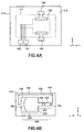
- FIGs 2A and 2B are respectively a plan view and a side elevation of a first embodiment 100 of a metallic contact electrical switch in accordance with the invention.
- Figure 2C is a cut-away plan view of switch 100 showing its internal structure.
- a Lorentz actuator generates a motive force that is used to control the position of a conducting switching liquid relative to a pair of electrical switch contacts.
- the Lorentz actuator generates the motive force by a control current passing through a conducting actuating liquid located in a magnetic field supplied by a magnet.
- the control current is applied to the actuating liquid through opposed control electrodes.
- Switch 100 has a housing 110 that defines a cavity 120 in which is located conducting switching liquid 130.
- Switch contacts 140 and 141 are also located in cavity 120 in electrical contact with switching liquid 130 in at least one of the switching states of switch 100.
- a Lorentz actuator 150 that comprises conducting actuating liquid 152 located in cavity 120 and is capable of movement in the cavity is mechanically coupled to the switching liquid 130 to change the switching state of switch 100.
- cavity 120 is elongate and linear and has a switching portion 122 and an actuating portion 124.
- Switch contacts 140 and 141 are located in the switching portion 122 of cavity 120.
- Lorentz actuator 150 is composed of conducting actuating liquid 152 located in the actuating portion 124 of cavity 120; opposed control electrodes 160 and 162 located in the actuating portion 124 of cavity 120 in electrical contact with actuating liquid 152 in at least one of the switching states of switch 100, and a magnet 170 located adjacent the actuating portion 124 of cavity 120.
- the actuating portion 124 of cavity 120, control electrodes 160 and 162, and magnet 170 are arranged such that the direction of current flow through actuating liquid 152 between control electrodes 160 and 162, the direction of the magnetic field applied by magnet 170 to actuating liquid 152 and direction in which actuating liquid 152 is capable of moving in the actuating portion 124 of cavity 120 are mutually orthogonal.
- Actuating liquid 152 is coupled to switching liquid 130 by an insulating fluid 154.
- Insulating fluid 154 electrically isolates switching liquid 130, and, hence, switch contacts 140 and 141, from actuating liquid 152 and from the electrical circuit formed in part by control electrodes 160 and 162 and actuating liquid 152.
- insulating fluid 154 may be omitted.
- a single body of conducting liquid constitutes actuating liquid 152 and switching liquid 130.
- Switching liquid 130, actuating liquid 152 and, if present, insulating fluid 154 collectively constitute a moving element 158.
- conducting and insulating are used in this disclosure in a relative sense.
- a material described as conducting has a greater electrical conductivity than a material described as insulating.
- the ratio of the electrical conductivities of the conducting material and the insulating material depends on the application in which the switch will be used. A greater ratio is needed in applications that need the switch have a large ratio of OFF to ON resistance than in applications in which the switch having a smaller ratio of OFF to ON resistance are acceptable.
- magnet 170 is a permanent magnet. In other embodiments, magnet 170 is an electromagnet. The location of magnet 170 is indicated by a broken line in Figure 2C.
- cavity 120 additionally comprises a pressure equalizing portion that extends between the remote end of switching portion 122 and the remote end of actuating portion 124.
- the remote end of switching portion 122 is the end of switching portion 122 remote from actuating portion 124 and the remote end of actuating portion 124 is the end of actuating portion 124 remote from switching portion 122.
- the pressure equalizing portion allows moving element 158 to move freely in the x-direction in cavity 120 by enabling fluid filling the portions of cavity 120 not occupied by the moving element to flow back and forth between the remote end of switching portion 122 and the remote end of actuating portion 124 when the switching state of switch 100 changes.
- the pressure equalizing portion of cavity 120 will be described in more detail below with reference to Figure 4B.
- Figures 3A and 3B are cross-sectional views along the section line 3A-3A in Figure 2C of switch 100 in its two switching states.
- Figures 3A and 3B show the direction of the magnetic field B that magnet 170 applies to actuating liquid 152 in Lorentz actuator 150.
- Figure 3A shows the result of applying a control voltage between control electrode 162 and control electrode 160 ( Figure 2C).
- the control voltage causes a control current to flow through actuating liquid 152 in the +y-direction from control electrode 162 to control electrode 160.
- Interaction of the control current and magnetic field B applies a motive force F in the -x-direction to actuating liquid 152.
- Motive force F moves actuating liquid 152 in the -x-direction in the actuating portion 124 of cavity 120.
- Switching liquid 130 is coupled to actuating liquid 152 by insulating fluid 154.
- motive force F moves moving element 158 composed of switching liquid 130, insulating fluid 154 and actuating liquid 152 in the -x-direction to a position in the switching portion 122 of cavity 120 in which switching liquid 130 electrically connects switch contacts 140 and 141.
- Figure 3B shows the result of applying a control voltage between control electrode 160 and control electrode 162.
- the control voltage causes a control current to flow through actuating liquid 152 in the -y-direction from control electrode 160 to control electrode 162.
- Interaction of the control current and magnetic field B applies a motive force F' in the +x-direction to actuating liquid 152.
- Motive force F' moves moving element 158 in the +x-direction in cavity 120 to a position in which the electrical connection between switch contacts 140 and 141 provided by switching liquid 130 is broken.
- the distance that moving element 158 moves in the x-direction depends on the temporal duration of the control voltage and the dynamics of the moving element in cavity 120.
- the control voltage is timed to move the moving element over a distance that alternately puts switching liquid 130 in contact with and out of contact with switch contacts 140 and 141.
- the distance through which the moving element moves can alternatively be defined by the amount of electrical charge that passes between control electrodes 160 and 162 and vice versa. Other ways of defining the distance through which moving element 158 moves in cavity 120 are described below.
- housing 110 is composed of a first substrate 112 and a second substrate 114.
- Second substrate 114 is bonded to first substrate 112.
- First substrate 112 and second substrate 114 are shown in more detail in Figures 4A and 4B, respectively.
- Figure 4A is a plan view of first substrate 112. Broken lines show the locations of second substrate 114 on the first substrate and of cavity 120 in the second substrate.
- First substrate 112 has a planar major surface 113 (also shown in Figure 3A) on which switch contacts 140 and 141 and control electrodes 160 and 162 are located.
- Second substrate 114 has a planar major surface 115 that is juxtaposed with surface 113 of first substrate 112 in switch 100.
- Figure 4B is a view of the major surface 115 of second substrate 114.
- Cavity 120 composed of switching portion 122 and actuating portion 124, is defined in substrate 114.
- the width, i.e., dimension in the y-direction, of actuating portion 124 is greater than that of switching portion 122.
- actuating portion 124 is greater in cross-sectional area than switching portion 122.
- switching portion 122 and actuating portion 124 are equal in either or both of width and cross-sectional area.
- Cavity 120 is located in substrate 114 such that, when substrates 112 and 114 are assembled to form switch 100, part of each of the switch contacts 140 and 141 is located inside the switching portion 122 of cavity 120 in contact with switching liquid 130 and part of each of the control electrodes 160 and 162 is located inside the actuating portion 124 of cavity 120 in contact with actuating liquid 152.
- Figure 4B also shows switching liquid 130 occupying part of switching portion 122 of cavity 120, actuating liquid 152 occupying parts of switching portion 122 and actuating portion 124, and insulating fluid 154 occupying part of switching portion 122 between the parts occupied by switching liquid 130 and actuating liquid 152.
- Figure 4B also shows an embodiment of cavity 120 additionally having the above-mentioned optional pressure equalizing portion 126 defined in substrate 114.
- Pressure equalizing portion 126 extends between the remote end of the switching portion 122 and the remote end of actuating portion 124.
- the portion of cavity 120 not occupied by moving element 158 is filled with an insulating fluid 155.
- Pressure equalizing portion 126 allows insulating fluid 155 to flow back and forth between the remote end of switching portion 122 and the remote end of actuating portion 124 to equalize pressure across moving element 158 as switch 100 changes state.
- the material of insulating fluid 155 may be the same as, or different from, that of insulating fluid 154.
- pressure equalizing portion 126 is dimensioned and insulating fluid 155 is chosen to provide switch 100 with specific dynamic switching properties. In other embodiments, pressure equalizing portion 126 is dimensioned and insulating fluid 155 is chosen to impart a negligible change on the dynamic switching properties on switch 100. Pressure equalizing portion 126 may alternatively be defined at least in part in first substrate 112 ( Figure 4A).
- Switch 100 is a single-pole, single-throw, i.e., ON-OFF, switch.
- Other embodiments of a switch in accordance with the invention provide additional poles and additional throws.
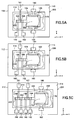
- FIGS 5A and 5B are cut-away plan views showing the internal structure of a second embodiment 200 of a metallic contact switch in accordance with the invention in each of its switching states.
- Switch 200 is a single-pole, double-throw switch, i.e., a two-way switch. Elements of switch 200 that correspond to elements of above-described switch 100 are indicated by the same reference numerals and will not be described again here.
- Switch 200 has a third switch contact 142 located on the major surface 113 of substrate 112.
- Switch contact 142 is located in and extends from the switching portion 122 of cavity 120 and is in electrical contact with switching liquid 130 in one of the switching states of switch 200.
- switch contacts 140, 141 and 142 are arrayed in order in the x-direction along the length of switching portion 122.
- the term length used in connection with an element, such as cavity 120 denotes the dimension of the element in the x-direction.
- Switch contacts 140, 141 and 142 have a nominally uniform pitch, i.e., switch contacts 140, 141 and 142 are separated in the x-direction by nominally-equal distances. However, a functioning switch will be obtained with some deviation from a uniform pitch.
- switch contact 141 is located on the opposite side of switching portion 122 from switch contacts 140 and 142, i.e., common switch contact 141 extends in the +y-direction from switching portion 122, whereas switch contacts 140 and 142 extend in the -y-direction from switching portion 122.
- This arrangement reduces capacitance between common switch contact 141 and switch contacts 140 and 142.
- switch contacts 140, 141 and 142 are all located on the same side of switching portion 122, i.e., all three switch contacts extend from switching portion 122 in the same direction.
- the length of switching liquid 130 in the switching portion 122 of cavity 120 is greater than the distance between switch contacts 140 and 141, but less than the distance between the adjacent edges of switch contacts 140 and 142.
- Figure 5A shows switch 200 in one of its switching states in which switching liquid 130 contacts switch contacts 140 and 141, and switch contact 142 contacts insulating fluid 154. In this switching state, switching liquid 130 electrically connects switch contact 140 to switch contact 141, and switch contact 142 is electrically isolated.
- Figure 5B shows switch 200 after a control current has passed from control electrode 160 to control electrode 162 to generate a motive force in the +x-direction.
- the motive force has moved actuating liquid 152 in the +x-direction and the actuating liquid has moved switching liquid 130 in the +x-direction by a distance approximately equal to the pitch of switch contacts 140, 141 and 142.
- the movement of switching liquid 130 has put switching liquid 130 in contact with switch contacts 141 and 142. In this switching state, switching liquid 130 electrically connects switch contact 142 to switch contact 141, and switch contact 140 is electrically isolated.
- Switch 200 is returned to its switching state shown in Figure 5A by passing a control current from control electrode 162 to control electrode 160.
- FIG. 5C is a cut-away plan view showing the internal structure of an embodiment 202 of a double-pole, double-throw switch in one of its switching states.
- Switch 202 is based on single-pole, double-throw, switch 200 described above with reference to Figures 5A and 5B.
- Elements of switch 202 that correspond to elements of the switches described above with reference to Figures 2A, 2B, 5A and 5B are indicated by the same reference numerals and will not be described again here.
- switch contacts 240, 241 and 242 are arrayed in the x-direction on major surface 213 of first substrate 212 next to switch contacts 140, 141 and 142.
- Switch contacts 240, 241 and 242 have the same pitch as switch contacts 140, 141 and 142.
- Switch contact 242 is separated from switch contact 140 by a distance different from the pitch of the switch contacts. In another embodiment, switch contact 242 is separated from switch contact 140 by a distance equal to the pitch of the switch contacts.
- second substrate 214 Defined in second substrate 214 is a cavity 220 similar to cavity 120 shown in Figure 5A.
- Cavity 220 has a switching portion 222 and an actuating portion 224.
- switching portion 222 is extended in the -x-direction to accommodate switch contacts 240, 241 and 242 in addition to switch contacts 140, 141 and 142.
- Switching liquid 230 and insulating fluid 254 are disposed in tandem with switching liquid 130 and insulating fluid 154 in switching portion 222.
- the length of switching liquid 230 and the length of switching liquid 130 in the switching portion 222 of cavity 220 are approximately equal.
- the length of insulating fluid 254 in switching portion 222 is approximately equal to the distance between switch contacts 140 and 242.
- FIG. 5C shows switch 202 in the one of its switching states corresponding to the switching state shown in Figure 5A.
- Switching liquid 130 electrically contacts switch contacts 140 and 141, switch contact 142 contacts insulating fluid 154, switching liquid 230 electrically contacts switch contacts 240 and 241, and switch contact 242 contacts insulating fluid 254.
- switching liquid 130 electrically connects switch contact 140 to switch contact 141, switch contact 142 is electrically isolated, switching liquid 230 electrically connects switch contact 240 to switch contact 241, and switch contact 242 is electrically isolated.
- switching liquid 130 contacts switch contacts 141 and 142, switch contact 140 contacts insulating fluid 254, switching liquid 230 contacts switch contacts 241 and 242, and switch contact 240 is electrically isolated.
- switching liquid 130 electrically connects switch contact 141 to switch contact 142, switch contact 140 is electrically isolated, switching liquid 230 electrically connects switch contact 241 to switch contact 242, and switch contact 240 is electrically isolated.
- FIGS. 6A and 6B are cut-away plan views showing the internal structure of a third embodiment 300 of a metallic contact switch in accordance with the invention in each of its switching states.
- Switch 300 is a double-pole, double-throw switch. Elements of switch 300 that correspond to elements of the switches described above are indicated by the same reference numerals and will not be described again here.
- cavity 320 having a switching portion 122, an actuating portion 324 and a switching portion 322 arranged in tandem in the x-direction.
- actuating liquid 152 Located in switching portion 122 is part of actuating liquid 152, insulating fluid 154 and switching liquid 130 in an arrangement similar to that of actuating liquid 152, insulating fluid 154 and switching liquid 130 in the switching portion 122 of cavity 120 described above with reference to Figures 2A-2C.
- Actuating liquid 152 additionally fills actuating portion 324 of cavity 320 and part of switching portion 322.
- Switching portion 322 additionally accommodates insulating fluid 354 and switching liquid 330 arranged in tandem in an arrangement that is a mirror image of the arrangement of insulating fluid 154 and switching liquid 130 in switching portion 322.
- Switch 300 has three switch contacts 140, 141 and 142 located on the major surface 313 of substrate 312. Switch contacts 140, 141 and 142 are located in and extend from switching portion 122 of cavity 320 in a manner similar to that described above with reference to Figure 5A. Switch 300 additionally has three switch contacts 340, 341 and 342 located on major surface 313 of substrate 312. Switch contacts 340, 341 and 342 are located in and extend from the switching portion 322 of cavity 320. Switch contacts 340, 341 and 342 are arrayed in order in the -x-direction along the length of switching portion 322. Switch contacts 340, 341 and 342 have a nominally uniform pitch as described above, but a functioning switch will be obtained even with some deviation from uniformity.
- switch contact 341 extends from switching portion 322 in the opposite direction to switch contacts 340 and 342, but may alternatively extend from switching portion 322 in the same direction as switch contacts 340 and 342.
- the length of switching liquid 130 in switching portion 122 of cavity 320 is greater than the distance between switch contacts 140 and 141, but less than the distance between the adjacent edges of switch contacts 140 and 142 as described above.
- the length of switching liquid 330 in switching portion 322 is greater than the distance between switch contacts 340 and 341, but less than the distance between the adjacent edges of switch contacts 340 and 342.
- FIG. 6A shows switch 300 in one of its switching states in which switching liquid 130 makes contact with switch contacts 140 and 141, switch contact 142 contacts insulating fluid 154, switching liquid 330 makes contact with switch contacts 340 and 341 and switch contact 342 is electrically isolated.
- switching liquid 130 electrically connects switch contact 140 to switch contact 141
- switch contact 142 is electrically isolated
- switching liquid 330 electrically connects switch contact 340 to switch contact 341
- switch contact 342 is electrically isolated.
- Figure 6B shows switch 300 after a control current has passed from control electrode 160 to control electrode 162 to generate a motive force that has moved actuator liquid 152 in the +x-direction.
- Actuator liquid moving the +x-direction has moved moving element 358, composed of switching liquid 130, insulating fluid 154, actuating liquid 152, insulating fluid 354 and switching liquid 330, in the +x-direction.
- Switching liquid 130 and switching liquid 330 have moved through a distance equal to the pitch of the switch contacts.
- the movement of moving element 358 puts switching liquid 130 in contact with switch contacts 141 and 142, switching liquid 330 in contact with switch contacts 341 and 342 and insulating fluid 354 in contact with switch contact 340.
- switching liquid 130 electrically connects switch contact 141 to switch contact 142
- switch contact 140 is electrically isolated
- switching liquid 330 electrically connects switch contact 341 to switch contact 342
- switch contact 340 is electrically isolated.
- a double-pole, single-throw switch can be made based on the embodiment shown in Figures 6A and 6B by omitting switch contact 140 or switch contact 142 and by omitting switch contact 340 or switch contact 342.
- the identity of the omitted switch contacts determines whether the poles of the switch are ON (or OFF) simultaneously or alternately.
- double-pole, single-throw switch can be made based on the embodiment shown in Figure 5C by omitting switch contact 140 or switch contact 142 and by omitting switch contact 240 or switch contact 242.
- the identity of the omitted switch contacts determines whether the poles of the switch are ON (or OFF) simultaneously or alternately.
- FIG. 7A is a cut-away plan view showing the internal structure of a fourth embodiment 400 of a metallic contact switch in accordance with the invention one of its switching states. Elements of switch 400 that correspond to elements of the switches described above are indicated by the same reference numerals and will not be described again here.
- Switch 400 is a single-pole, single-throw switch in which Lorentz actuator 450 is configured to define the travel of actuating liquid 152 in the actuating portion 124 of cavity 120. The defined travel of actuating liquid 152 in turn defines the travel of switching liquid 130 in the switching portion 122 of cavity 120 relative to switch contacts 140 and 141.
- the other switch embodiments described herein may be similarly modified to incorporate a Lorentz actuator in which the actuating liquid has a defined travel.
- control electrodes 160, 462 and 464 are located in actuating portion 124 of cavity 120.
- Control electrode 160 is located on one side of actuating portion 124 and, in the example shown, is elongate in the x-direction.
- Control electrodes 462 and 464 are located opposite control electrode 160 on the other side of actuating portion 124, and are separated from one another in the x-direction and from control electrode 160 in the y-direction.
- Each of the control electrodes 462 and 464 is smaller in length than control electrode 160. Alternatively, with proper positioning of control electrode 160, electrodes 160, 462 and 464 may all be approximately equal in length.
- Actuating liquid 152 occupies part of the length of the actuating portion 124 of cavity 120.
- Insulating fluid 154 occupies part of the actuating portion 124 and part of the switching portion 122 of cavity 120 between actuating liquid 152 and switching liquid 130.
- Figure 7A shows switch 400 in an exemplary initial switching state in which switching liquid 130 electrically connects switch contacts 140 and 141 and actuating liquid 152 is in electrical contact with control electrode 462 and control electrode 160, but does not make electrical contact with control electrode 464.
- FIGS 8A-8D illustrate the operation of switch 400 starting at the exemplary initial switching state shown in Figure 7A.
- a negative control voltage is applied between control electrode 160 (nominally ground) and control electrode 462, as shown in Figure 8A. Consequently, a control current, represented by arrow 480, flows in the y-direction from control electrode 160 to control electrode 462.
- Control current 480 and magnetic field B (see Figure 3A) generate a motive force, represented by an arrow 481, in the +x-direction.
- Motive force 481 moves actuating liquid 152 and, hence, moving element 158, composed of actuating liquid 152, insulating fluid 154 and switching liquid 130, in the +x-direction.
- actuating liquid 152 moves into contact with control electrode 464 and switching liquid 130 moves out of contact with switch contact 140.
- the loss of contact between switching liquid 130 and switch contact 140 breaks the electrical circuit between switch contacts 140 and 141.
- Switch 400 remains in the switching state shown in Figure 8B until a positive control voltage is applied between control electrode 160 (nominally ground) and control electrode 464, as shown in Figure 8C.
- a control current represented by arrow 482 flows in the +y-direction from control electrode 464 to control electrode 160.
- Control current 482 and magnetic field B (see Figure 3A) generate a motive force, represented by an arrow 483, in the -x-direction.
- Motive force 483 moves actuating liquid 152 and, hence, moving element 158, in the -x-direction.
- actuating liquid 152 moves back into contact with control electrode 462 and switching liquid 130 moves into contact with switch contact 140.
- the contact between switching liquid 130 and switch contact 140 re-establishes the electrical circuit between switch contacts 140 and 141.
- Figure 7B is a cut-away plan view of a variation 402 on switch 400 shown in Figure 7A in which the need for a bipolar control voltage is eliminated.
- control electrode 160 is replaced by a control electrode 460 located in actuating portion 124 opposite control electrode 462 and a control electrode 466 located in actuating portion 124 opposite control electrode 464.
- Control electrodes 460 and 466 are typically mirror images of control electrodes 462 and 464, respectively.
- a control voltage is applied between control electrode 462 (nominally ground) and control electrode 460 (high) to generate a motive force in the +x-direction to change switch 402 from the switching state shown in Figure 7B to a switching state similar to that shown in Figure 8B.
- the movement of actuating liquid 152 in the +x-direction breaks the electrical circuit shown in Figure 7B between control electrodes 460 and 462 and establishes an electrical circuit between control electrodes 464 and 466.
- Switch 402 is returned to its switching state shown in Figure 7B by applying a control voltage between control electrode 466 (nominally ground) and control electrode 464 (high) to generate a motive force in the -x-direction.
- the motion of the actuating liquid in the -x-direction re-establishes the electrical circuit between control electrodes 460 and 462 and breaks the electrical circuit between control electrodes 464 and 466.
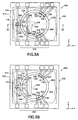
- FIGS 9A and 9B are cut-away plan views showing the internal structure of a fifth embodiment 500 of a metallic contact switch in accordance with the invention in each of its switching states.
- Switch 500 has a toroidal cavity.
- Figure 9C is a cross-sectional view along the section line 9C-9C in Figure 9A.
- Figures 9D and 9E are plan views of the first and second substrates, respectively, of switch 500.
- the example of switch 500 shown is a double-pole, double-throw switch. Other examples have different numbers of poles and/or throws.
- Elements of switch 500 that correspond to elements of the switches described above with reference to Figures 2A, 2B, 5A, 5B, 6A and 6B are indicated by the same reference numerals and will not be described again here.
- Switch 500 is composed of a housing 510 that defines a toroidal cavity 520; conducting switching liquid 130 located in cavity 520; switch contacts 140, 141 and 142 located in cavity 520 in electrical contact with switching liquid 130 in at least one of the switching states of switch 500; and a Lorentz actuator 550 mechanically coupled to switching liquid 130 to change the switching state of the switch.
- Switching liquid 130 is located in a switching portion 522 of cavity 520.
- Switch 500 also has conducting switching liquid 530 located in a switching portion 526 of cavity 520, and switch contacts 540, 541 and 542 located in switching portion 526 of cavity 520 in electrical contact with switching liquid 530 in at least one of the switching states of switch 500.
- Lorentz actuator 550 is composed of conducting actuating liquid 152 located in an actuating portion 524 of cavity 520, control electrodes 560 and 562 located in actuating portion 524 of cavity 520 in electrical contact with actuating liquid 152 and a magnet 570 located adjacent actuating portion 524 of cavity 520.
- the actuating portion 524 of cavity 520, control electrodes 560 and 562, and magnet 570 are arranged such that the direction of current flow through actuating liquid 152 between control electrodes 560 and 562, the direction of the magnetic field applied by magnet 570 to actuating liquid 152 and the resulting direction of motion of actuating liquid 152 in cavity 520 are mutually orthogonal.
- control electrodes 560 and 562 are in electrical contact with actuating liquid 152 in one of the switching states of switch 500.
- Lorentz actuator 550 additionally has opposed control electrodes 564 and 566 located in actuating portion 524 of cavity 520 in electrical contact with actuating liquid 152 in the other of the switching states of switch 500. Together with control electrodes 560 and 562, control electrodes 564 and 566 define the travel of actuating liquid 152, and, hence, switching liquid portions 130 and 530, in cavity 520 in a manner similar to that described above with reference to Figure 7B.
- Insulating fluid portions 154 and 554 mechanically couple actuating liquid 152 of Lorentz actuator 550 to switching liquid 130 and switching liquid 530, respectively. Additionally insulating fluid portion 556 mechanically couples switching liquid 130 and to switching liquid 530.
- housing 510 is composed of a first substrate 512 and a second substrate 514 bonded to first substrate 512.
- Figure 9E shows the major surface 515 of second substrate 514 that faces first substrate 512.
- Toroidal cavity 520 extends into second substrate 514 from major surface 515.
- switching portion 522, actuating portion 524 and switching portion 526 of cavity 520 are arranged in tandem. In the example shown, switching portion 522, actuating portion 524 and switching portion 526 are simply circumferential regions of cavity 520 and do not differ from one another structurally.
- switching portion 522, actuating portion 524 and switching portion 526 differ from one another structurally.
- actuating portion 524 differs in cross-sectional area from switching portions 522 and 526.
- one or more of the portions of cavity 520 between switching portion 522, actuating portion 524 and switching portion 526 differ in cross-sectional area from switching portion 522, actuating portion 524 and switching portion 526 to impose specific dynamic switching properties on switch 500.
- Figure 9E also shows switching liquid 130, actuating liquid 152 and switching liquid 530 located in switching portion 522, actuating portion 524 and switching portion 526, respectively, of cavity 520, and insulating fluid portions 154, 556 and 554 occupying the portions of cavity 520 not occupied by switching liquid 130, actuating liquid 152 and switching liquid 556.
- Figure 9D shows the major surface 513 of first substrate 512 that faces second substrate 514.
- the positions on first substrate 512 of second substrate 514 and of toroidal cavity 520 in the second substrate are indicated in Figure 9D by broken lines.
- Located on major surface 513 are three switch contacts 140, 141 and 142 located in and extending radially from the switching portion 522 of cavity 520.
- three switch contacts 540, 541 and 542 are located on major surface 513 circumferentially offset in the clockwise direction from switch contacts 140, 141 and 142.
- Switch contacts 540-542 are located in and extend radially from the switching portion 526 of cavity 520.
- Switch contacts 140-142 are circumferentially arrayed in counterclockwise order along switching portion 522 and switch contacts 540-542 are circumferentially arrayed in counterclockwise order along switching portion 526.
- Switch contacts 140-142 have nominally uniform angular separations, but a functioning switch will be obtained even with some deviation from uniformity.
- Switch contacts 540-542 have nominally uniform angular separations equal to those of switch contacts 140-142, but a functioning switch will be obtained even with some deviation from uniformity and equality.
- the circumferential distance between the ends of switching liquid 130 in the switching portion 522 of cavity 520 is greater than the circumferential distance between switch contacts 140 and 141, but less than the circumferential distance between the adjacent edges of switch contacts 140 and 142.
- the circumferential distance between the ends of switching liquid 530 in switching portion 526 is greater than the circumferential distance between switch contacts 540 and 541, but less than the circumferential distance between the adjacent edges of switch contacts 540 and 542.
- Control electrodes 560, 562, 564 and 566 are also located on the major surface 513 of first substrate 512.
- Control electrodes 560 and 562 are located radially opposite one another on opposite sides of the actuating portion 524 of cavity 520 and extend radially outwardly and inwardly, respectively, from the actuating portion.
- Control electrodes 566 and 564 are located radially opposite one another on opposite sides of the actuating portion 524 of cavity 520, are circumferentially offset in the counterclockwise direction from control electrodes 560 and 562, respectively, and extend radially outwardly and inwardly, respectively, from the actuating portion.
- the angle through which the actuating liquid 152 of Lorentz actuator 550 rotates about the center 528 of toroidal cavity 520 is given by the difference between the angle subtended at center 528 by actuating liquid 152 and the angle subtended at center 528 by the adjacent edges of control electrodes 562 and 564.
- FIG. 9A shows switch 500 in one of its switching states in which switching liquid 130 is in electrical contact with switch contacts 140 and 141, and switch contact 142 contacts insulating fluid 154, and switching liquid 530 is in electrical contact with switch contacts 540 and 541 and switch contact 542 contacts insulating fluid 556.
- switching liquid 130 electrically connects switch contact 140 to switch contact 141
- switch contact 142 is electrically isolated
- switching liquid 530 electrically connects switch contact 540 to switch contact 541
- switch contact 542 is electrically isolated.
- control electrodes 560 and 562 are in electrical contact with actuating liquid 152 whereas control electrodes 564 and 566 are in contact with insulating fluid 554.
- Figure 9B shows switch 500 after a control voltage has been applied between control electrode 560 and control electrode 562.
- a control current flowing through actuating liquid 152 generates a motive force that moves actuating liquid 152 clockwise until the electrical contact between actuating liquid 152 and control electrodes 560 and 562 breaks.
- the counterclockwise motion of actuating liquid 152 moves moving element 558, composed of actuating liquid 152, insulating fluid 154, switching liquid 130, insulating fluid 556, switching liquid 530 and insulating fluid 554, counterclockwise through an angle about center 528 approximately equal to the angular pitch of the switch contacts.
- switch contact 140 is electrically isolated
- switching liquid 130 electrically connects switch contact 141 to switch contact 142
- switch contact 540 is electrically isolated
- switching liquid 530 electrically connects switch contact 541 to switch contact 542.
- the counterclockwise movement of actuating liquid 152 puts actuating liquid 152 in contact with control electrodes 564 and 566.
- a control voltage is applied control electrodes 564 and 566.
- the resulting control current flowing through actuating liquid 152 generates a motive force that moves actuating liquid 152 clockwise until the electrical contact between actuating liquid 152 and control electrodes 564 and 566 breaks.
- the clockwise motion of actuating liquid 152 moves moving element 558 clockwise through an angle about center 528 approximately equal to the angular pitch of the switch contacts. This restores switch 500 it its switching state described above with reference to Figure 9A.
- a double-pole, single-throw switch can be made based on the double-pole- double-throw example shown in Figures 9A and 9B by omitting switch contact 140 or switch contact 142 and by omitting switch contact 540 or switch contact 542.
- the identity of the omitted switch contacts determines whether the poles of the switch are ON (or OFF) simultaneously or alternately.
- More poles can be incorporated into the switch 500 described above with reference to Figures 9A and 9B by increasing the number of portions of switching liquid in cavity 520.
- the portions of switching liquid are circumferentially spaced from one another and from switching liquid 130, switching liquid 530 and actuating liquid 152.
- Portions of insulating fluid fill the portions of cavity 520 not occupied by the switching liquid portions and the actuating liquid.
- Additional sets of switch contacts are located on the major surface 513 of first substrate 512 in locations corresponding to the locations of the additional switching liquid portions.
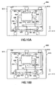
- FIGS 10A and 10B are cut-away views showing the internal structure of a sixth embodiment 600 of a metallic contact switch in accordance with the invention.
- a Lorentz actuator is used to control the electrical continuity of a conducting switching liquid relative to a set of switch contacts.
- the switch contacts remain in continuous electrical contact with the switching liquid.
- the Lorentz actuator generates an actuation force by passing a control current through a conducting actuating liquid located in a magnetic field.
- the control current is provided to the actuating liquid via opposed control electrodes.
- Switch 600 is composed of a housing 610 that defines a cavity 620; conducting switching liquid 130 located in cavity 620; switch contacts 140, 141 and 142 located in cavity 620 in electrical contact with switching liquid 130 in both of the switching states of switch 600; and a Lorentz actuator 650 mechanically coupled to switching liquid 130 to change the switching state of the switch.
- Cavity 620 is composed of a switching portion 622, an actuating portion 624 and coupling portions 626 and 628.
- Actuating portion 624 is substantially parallel to switching cavity 622 and is offset from switching cavity 622 in the y-direction.
- Coupling portions 626 and 628 extend from opposite ends of actuating portion 624 to switching portion 622 and join switching portion 622 at points offset from one another along the length of the switching portion.
- Switching liquid 130 occupies most of switching portion 622 of cavity 620.
- Actuating liquid 152 occupies actuating portion 624, part of coupling portion 626 and part of coupling portion 628.
- Insulating fluid 154 occupies the remainder of coupling portion 626 and, in the switching state shown in Figure 10A, the remainder of switching portion 622.
- Insulating fluid 654 occupies the remainder of coupling portion 628.
- Switch contacts 140, 141 and 142 are located in and extend from switching portion 622 of cavity 620.
- Switch contacts 140, 141 and 142 are arrayed in the x-direction along the length of switching portion 622 and are interleaved with coupling portions 626 and 628.
- Switch contact 141 is located between coupling portions 626 and 628, switch contact 140 is located in switching portion 622 on the opposite side of coupling portion 626 from switch contact 141 and switch contact 142 is located in switching portion 622 on the opposite side of coupling portion 628 from switch contact 141.
- Lorentz actuator 650 is composed of conducting actuating liquid 152 located in the actuating portion 624 of cavity 620, opposed control electrodes 160 and 162 located in and extending from actuating portion 624 in electrical contact with actuating liquid 152 and a magnet 170 located adjacent actuating portion 624.
- Actuating portion 624, control electrodes 160 and 162, and magnet 170 are arranged such that the direction of current flow through actuating liquid 152 between control electrodes 160 and 162, the direction of the magnetic field applied by magnet 170 to actuating liquid 152 and the resulting direction of motion of actuating liquid 152 in actuating portion 624 are mutually orthogonal.
- insulating fluid 154 occupies part of switching portion 622 of cavity 620 in addition to part of coupling portion 626.
- the portion of insulating fluid 154 occupying part of switching portion 622 divides switching liquid 130 into a switching liquid portion 632 in electrical contact only with switch contact 140 and a switching liquid 634 portion in electrical contact with switch contacts 141 and 142.
- switching liquid portion 634 electrically connects switch contacts 141 and 142, but insulating fluid 154 electrically insulates switch contact 140 from the other two switch contacts.
- Figure 10B shows the switching state of switch 600 after a control voltage has been applied between control electrode 160 and control electrode 162.
- the motive force generated by the interaction of the resulting control current passing through actuating liquid 152 and the magnetic field generated by magnet 170 moves actuating liquid 152 in the +x-direction.
- the movement of actuating liquid 152 in the +x-direction drives insulating fluid 654 through the coupling portion 628 of cavity 620 into switching portion 622, where insulating fluid 654 divides switching liquid portion 634 into switching liquid portion 636 that remains in electrical contact only with switch contact 142 and a switching liquid portion that moves in the -x-direction in the switching portion 622 of cavity 620.
- the moving switching liquid portion expels insulating fluid 154 from the switching portion, which allows the moving switching liquid portion to join with switching liquid portion 632 to form switching liquid portion 638.
- Switching liquid portion 638 is in electrical contact with switch contacts 140 and 141.
- switching liquid portion 638 electrically connects switch contacts 140 and 141, but insulating fluid 654 electrically isolates switch contact 142 from the other two switch contacts.
- a control voltage is applied between control electrode 162 and control electrode 160.
- the motive force generated by the interaction of the resulting control current passing through actuating liquid 152 and the magnetic field generated by magnet 170 moves actuating liquid 152 in the -x-direction.
- the movement of actuating liquid 152 in the -x -direction drives insulating fluid 154 through the coupling portion 626 of cavity 620 into switching portion 622, where insulating fluid 154 divides switching liquid portion 638 into switching liquid portion 632 that remains in electrical contact only with switch contact 142, as described above, and a switching liquid portion that moves in the +x-direction in the switching portion 622 of cavity 620.
- the moving switching liquid portion expels insulating fluid 654 from the switching portion, which allows the moving switching liquid portion to join with switching liquid 636 to re-form switching liquid portion 634, described above.
- cavity 620 has an additional switching portion with switch contacts arrayed along its length in an arrangement similar to that of switching portion 622 described above.
- the switch contacts are interleaved with two additional coupling portions that extend to the opposite ends of actuating portion 624.
- the switching states of the above-described metallic contact switch embodiments are metastable.
- moving element 158 composed of switching liquid 130, insulating fluid 154 and actuating liquid 152, stops moving in cavity 120 and remains in the position to which it has moved until a control current flows once again.
- an external stimulus such as a mechanical shock or vibration, can cause moving element 158 to move in the cavity. Sufficient movement of the moving element can result in an undesired change the switching state of the switch.
- FIGS 11A and 11B are enlarged cut-away plan views showing part of a seventh embodiment 700 of a switch in which the structure of the cavity is modified to increase the stability of the switching states of the switch.
- the modified structure of the cavity reduces the ability of an external stimulus, such as a mechanical shock or vibration, to move the moving element in the cavity and, hence, to change the switching state of the switch.
- the modified cavity structure will be described with reference to the cavity of a single-pole, double-throw switch similar to that shown in Figures 5A and 5B.
- the cavities of the other embodiments of the switch described herein may be similarly modified. Elements of the switch shown in Figures 11A and 11B that correspond to elements of the switches described above are indicated using the same reference numerals and will not be described again in detail.
- FIGS 11A and 11B show the switching portion 722 of the cavity 720 of switch 700.
- the remainder of switch 700 is not shown to simplify the drawing, but is similar to switch 200 described above with reference to Figures 5A and 5B.
- Switch contacts 140, 141 and 142 are located in and extend from the switching portion 722 of cavity 720.
- Switch contacts 140, 141 and 142 are arrayed in the x-direction along the length of switching portion 722 in a manner similar to that described above. Only the parts of switch contacts 140, 141 and 142 in and immediately adjacent switching portion 722 are shown to simplify the drawing.
- Switching portion 722 has constrictions 780, 781, 782 and 783 arrayed in the x-direction along its length. Constrictions 780-783 are interleaved with switch contacts 140-142. In each of constrictions 780-783, the cross-sectional area of switching portion 722 is less than that of the remainder of switching portion 722, e.g., less than that of the part of switching portion in which switch contact 140 is located. Constrictions 780 and 782 are separated in the x-direction and constrictions 781 and 783 are separated in the x-direction by respective distances approximately equal to, but not less than, the length of switching liquid 130 in switching portion 722.
- the moving element composed of switching liquid 130, insulating fluid 154 and actuating liquid 152 is free to move over a short distance in both the +x- and -x-directions. Electrical contact between switching liquid 130 and switch electrodes 140 and 141 is maintained over this range of movement.
- the end surface 131 of switching liquid 130 encounters constriction 780. The encounter decreases the radius of curvature of end surface 131, which generates a force in the +x-direction. The force resists further motion of the moving element in the -x-direction, and helps maintain contact between switching liquid 130 and switch contact 141.
- the end surface 153 of actuating liquid 152 encountering constriction 783 generates a force with a component in the +x-direction that additionally resists movement of the moving element in the -x-direction.
- Figure 11B shows switch 700 in its other switching state.
- the Lorentz actuator (not shown) of switch 700 generates a substantially greater motive force in the x-direction than the Lorentz actuator of switch 200 described above with reference to Figures 5A and 5B.
- the additional motive force is needed to drive the end surface 133 of switching liquid 130 through constriction 782 and to drive the end surface 131 of the switching liquid through constriction 781.
- interaction between the end surface 131 of switching liquid 130 and constriction 781 resists motion of the moving element in the +x-direction and helps maintain contact between the switching liquid and switch contact 141.
- interaction between the end surface 133 of switching liquid 130 and constriction 783 resists motion of the moving element in the x-direction and helps maintain contact between the switching liquid and switch contact 142.
- Constriction 784 is offset in the +x-direction relative to adjacent constriction 783. Interaction between the end surface 153 of actuating liquid 152 and constriction 784 resists further motion of the actuating liquid in the - x-direction, and, hence, helps maintain contact between switching liquid 130 and switch contact 142 in the switching state shown in Figure 11B.
- Additional constrictions may be located in the actuating portion (not shown) of cavity 720 to control the positioning of actuating liquid 152 in the actuating portion. Moreover, in embodiments with more than one switching portion, additional constrictions may be located in each switching portion.
- Figure 11C is an enlarged cut-away plan view showing an alternative switching portion 723 of the cavity 720 of switch 700 that increases the stability of the switching states of the switch.
- Alternative switching portion 723 reduces the ability of an external stimulus, such as a mechanical shock or vibration, to move the moving element lengthways in the cavity and, hence, to change the switching state of the switch.
- the alternative switching portion will be described with reference to the cavity of a single-pole, double-throw switch similar to that shown in Figures 5A and 5B.
- the cavities of the other embodiments of the switch described herein may be similarly modified.
- Switching portion 723 has an internal wall comprising alternate regions having a low wettability and a high wettability with respect to switching liquid 130.
- the terms high wettability and low wettability are used in a relative rather than an absolute sense.
- a material having a low wettability with respect to the switching liquid has a lower wettability with respect to the switching liquid and a material having a high wettability with respect to the switching liquid
- a material having a high wettability with respect to the switching liquid has a higher wettability with respect to the switching liquid and a material having a low wettability with respect to the switching liquid.
- switching portion 723 is defined in second substrate 114 ( Figure 2A, for example) with its internal wall 725 of a material having a high wettability with respect to switching liquid 130.
- Bands 785-788 are interleaved with switch contacts 140-142.
- Bands 785 and 787 are separated in the x-direction and bands 786 and 788 are separated in the x-direction by a distance approximately equal to, but not less than, the length of switching liquid 130 in switching portion 723.
- switching liquid 130 is mercury
- metals have a high wettability with respect to mercury and typical substrate materials have a low wettability with respect to mercury. However many metals form amalgams with mercury.
- the material of second substrate 114 has a low wettability with respect to mercury, and the wall 725 of the switching portion 722 of cavity 720 outside bands 785, 786, 787 and 788 is coated with a high wettability material, and the substrate material is exposed in bands 785, 786, 787 and 788.
- the wall outside bands 785, 786, 787 and 788 is coated with an adhesion layer of chromium (Cr) and a layer of a metal such as platinum (Pt) or iron (Fe) that is not dissolved by mercury to form an amalgam.
- the high-wettability material is rhodium (Rh).
- wall 725 is coated in bands 785, 786, 787 and 788 with a material having a low wettability with respect to the switching liquid. Glass and many plastics have a low wettability with respect to mercury.
- the moving element composed of switching liquid 130, insulating fluid 154 and actuating liquid 152 is free to move over a short distance in both the +x- and -x-directions in contact with switch electrodes 140 and 141. Electrical contact between switching liquid 130 and switch electrodes 140 and 141 is maintained over this range of movement.
- the end surface 131 of switching liquid 130 is in contact with wall 725 of high wettability material and therefore has a relatively large radius of curvature.
- the end surface 131 of switching liquid 130 encounters band 785 of low wettability material. The encounter decreases the radius of curvature of end surface 131, which generates a force in the +x-direction. This force resists further motion of the moving element in the -x-direction, and helps maintain contact between switching liquid 130 and switch contact 141.
- band 788 additionally has a low wettability with respect to actuating liquid 152
- the decrease in the radius of curvature of the end surface 153 of actuating liquid 152 resulting from end surface 153 encountering band 788 generates a force in the + x -direction that additionally resists movement of the moving element in the - x -direction in the switching state shown in Figure 11C.
- band 789 of a material having a low wettability with respect to actuating liquid 152 is also shown in Figure 11C.
- Band 789 is located in the +x-direction relative to adjacent band 788. Interaction between the end surface 153 of actuating liquid 152 and band 789 resists motion of actuating liquid 152 in the - x- direction,.and, hence, helps maintain contact between switching liquid 130 and switch contact 142 in the other switching state.
- Additional bands (not shown) of low-wettability material may be located in the actuating portion (not shown) of cavity 720 to control the positioning of actuating liquid 152 in the actuating portion.
- a combination of the bands of low-wettability material shown in Figure 11C and the constrictions shown in Figures 11A and 11B may be used in combination to control the position of the moving element in the cavity.
- the material of substrate 114 may have a low wettability with respect to switching liquid 130.
- the wall 725 of switching portion 723 is covered in regions corresponding to those between the bands 785-788 shown in Figure 11C with bands of a material having a high wettability with respect to switching liquid 130.
- Such bands are shaped to expose switch contacts 140-142 to switching liquid 130.
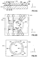
- FIGS 12A and 12B are respectively a plan view and a cross-sectional view of an eighth embodiment 800 of a metallic contact switch in accordance with the invention in which the magnitude of the control current needed for the Lorentz actuator to generate a given motive force is reduced.
- Switch 800 will be described with reference to a single-pole, single-throw switch similar to that described above with reference to Figures 2A-2B.
- Elements of switch 800 that correspond to elements of the switch described above with reference to Figures 2A-2C are indicated by the same reference numerals and will not be described again here.
- Lorentz actuators similar to those to be described next may be incorporated into the other embodiments of the switch described herein.
- a magnet assembly 870 incorporating magnet 170 applies the magnetic field to actuating liquid 152.
- magnet assembly 870 applies a substantially greater magnetic field to actuating liquid 152 than the arrangement described with reference to Figures 2A-2C in which the magnetic field is applied by magnet 170 affixed to second substrate 114 adjacent the actuating portion of the cavity.
- Magnet assembly 870 is composed of magnet 170 and ferromagnetic pole pieces 874 and 876. Magnet 170 is located adjacent one side of housing 110 with its polar axis orthogonal to the major surface 113 of first substrate 112. Pole piece 874 extends across second substrate 114 from magnet 170 to the region of substrate 114 in which the actuation portion 124 of cavity 120 is defined. The locations of cavity 120, and, in particular, the actuation portion 124 thereof, relative to pole piece 874 are shown by broken lines in Figure 12A.
- pole piece 876 extends across first substrate 112 from magnet 170 to the region of substrate 112 aligned with the actuation portion 124 of cavity 120 defined in substrate 114.
- the locations of cavity 120, and, in particular, the actuation portion 124 thereof, relative to pole pieces 874 and 876 are shown in Figure 12B.
- actuating liquid 152 is located in the high-intensity magnetic field that exists in a gap in the magnetic circuit formed by magnet 170 and pole pieces 874 and 876.
- Figure 12C is a cross-sectional view showing a variation 802 on switching device 800 in which first substrate 812 defines a recess 816 that accommodates pole piece 876.
- Pole piece 876 extends from magnet 170 to the region of substrate 812 aligned with the actuation portion 124 of cavity 820 defined in second substrate 114. The location of cavity 120, and, in particular, actuation portion 124, relative to pole pieces 874 and 876 is shown in Figure 12C. Locating pole piece 876 in recess 816 in first substrate 812 reduces the distance between pole pieces 874 and 876, which increases the strength of the magnetic field in the gap in the magnetic circuit in which actuating liquid 152 is located.
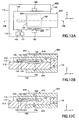
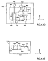
- Figures 13A, 13B and 13C are respectively two cut-away plan views and a cross-sectional view of a ninth embodiment 900 of a metallic contact switch in accordance with the invention in which the magnitude of the control current needed for the Lorentz actuator to generate a given motive force is further reduced, and which the resistance of the Lorentz actuator is increased.
- Figures 13D and 13E are plan views of the first and second substrates, respectively, of switch 900.
- Switch 900 will be described with reference to a single-pole, double-throw switch similar to that shown in Figures 5A and 5B. Elements of switch 900 that correspond to elements of the switches described above are indicated by the same reference numerals and will not be described again here. Lorentz actuators similar to that to be described next may be incorporated into the other embodiments of the switch described herein.
- cavity 920 is composed of a switching portion 122 and an actuating portion 924 in tandem in an arrangement similar to that described above.
- the length of actuating portion 924 is increased to accommodate part of insulating fluid 154, switching liquid 152, insulating fluid 954 and switching liquid 952 arranged in tandem in order in the x-direction.
- opposed control electrodes 960 and 964 are located in actuating portion 924 in electrical contact with switching liquid 152 and opposed control electrodes 966 and 962 in electrical contact with switching liquid 952.
- Control electrodes 960 and 962 extend from switching portion 924 to allow them to be connected to a control circuit (not shown).
- Control electrodes 964 and 966 are internally connected in series by a trace 961 ( Figure 13D) that extends across actuating portion 924 in the y-direction. Trace 961 is insulated from switching liquid portions 152 and 952 located in actuating portion 924. Alternatively, control electrodes 964 and 966 are similar in shape to control electrodes 960 and 962 and are externally connected in series.
- Magnet 970 is shaped to apply a magnetic field to actuating liquid 152 and actuating liquid 952 over their full range of travel in the actuating portion 924 of cavity 920.
- separate magnets may be used to apply respective magnetic fields to switching liquid 152 and switching liquid 952.
- an arrangement of pole pieces similar to that described above with reference to Figures 12A-12C may be used to apply a magnetic field to actuating liquid 152 and actuating liquid 952 collectively or individually.
- Insulating fluid 954 mechanically couples the motive force generated by passing a control current through switching liquid 952 to the motive force generated by additionally passing the control current through switching liquid 152.
- each of the actuating liquids 152 and 952 need generate only one-half of the motive force that Lorentz actuator 950 is required to generate to move moving element 958, composed of switching liquid 130, insulating fluid 154, actuating liquid 152, insulating fluid 954 and actuating liquid 952, in the +x- or -x-direction.
- the additional mass of insulating fluid 954 and actuating liquid 952 is less than that of switching liquid 130, insulating fluid 154 and actuating liquid 152, so that the control current through each of actuating liquid 152 and actuating liquid 952 is less than of a Lorentz actuator such as that shown in Figures 2A-2C having a single portion of actuating liquid.
- Control electrodes 964 and 966 are connected in series, so that a control voltage applied between control electrodes 960 and 962 or vice versa causes the same control current to pass through both actuating liquid 152 and actuating liquid 952.
- Lorentz actuators have a low electrical resistance: electrically connecting two Lorentz actuators in series as just described provides a Lorentz actuator with an increased electrical resistance that has a better impedance match with a typical control circuit.
- First substrate 913 is composed of a base 916 having electrically-conducting trace 961 located on its major surface. The remainder of the major surface of the base is covered by a planarizing layer 917. A layer 918 of an electrically-insulating material covers the planarizing layer and the trace. Switch contacts 140-142 and control electrodes 960, 962, 964 and 966 are located on the major surface of insulating layer 918. Referring additionally to Figure 13D, apertures in insulating layer 918 at both ends of trace 961 accommodate vias 963 and 965 electrically connected to the trace.
- Control electrode 964 is electrically connected to the end of via 963 remote from trace 961.
- Control electrode 966 is electrically connected to the end of via 966 remote from trace 961.
- vias 963 and 965 and trace 961 form an circuit that electrically connects control electrode 964 to control electrode 966.
- two portions of actuating liquid and respective pairs of opposed control electrodes are located in actuating portion 924.
- the number of portions of actuating liquid and respective opposed electrodes located in actuating portion 924 is greater than two. Additional traces, similar to trace 961, are provided to connect the electrodes contacting the portions of actuating liquid in series.
- the travel of the moving element of the Lorentz actuator is defined in a manner similar to that described above with reference to Figure 7B.
- two pair of opposed electrodes are located to make contact with each portion of actuating liquid in actuating portion 924.
- the electrodes for imparting forward motion and those for imparting reverse motion are separately connected in series.
- traces similar to trace 961 are provided at different levels in substrate 912 to provide the forward and reverse interconnections, respectively.
- switches are typically fabricated by wafer-scale processing in which wafers containing the respective substrates of hundreds or thousands of switches are processed and assembled. The assembled wafers are then singulated into individual switches or are divided into small arrays of switches.
- Switch 100 is fabricated as follows. Referring first to Figure 4A, a first wafer of which first substrate 112 forms part is provided. Examples of suitable materials for the first wafer are silicon, glass, ceramic and plastic. A metal substrate with an insulating layer on its major surface may alternatively be used.
- the switch contacts 140 and 141 and the control electrodes 160 and 162 of each switch are defined in a conducting material on one major surface of the first wafer.
- a conducting layer such as a layer of Pt or Fe, is deposited on the major surface of the wafer of which substrate 112 forms part.
- the conducting layer is patterned by etching or a lift-off process to define switch contacts 140 and 141 and control electrodes 160 and 162.
- the switch contacts and control electrodes are deposited on the major surface of the wafer by such processes as screen printing and lamination.
- the switch contacts and the control electrodes are of different materials.
- either or both of the switch contacts 140 and 141 and the control electrodes 160 and 162 are composed of layers of more than one material.
- the switch contacts and control electrodes are composed of a thin adhesion layer, a thick conduction layer of a high-conductivity material, and a thin contact layer of a material having a relatively high wettability with respect to switching liquid 130 and actuating liquid 152.
- the material of the contact layer is one that is insoluble in, and is not otherwise eroded by, the switching liquid and the actuating liquid.
- the material of the adhesion layer is titanium
- the material of the conduction layer is gold
- the material of the contact layer is rhodium.
- the adhesion layer is chromium and a combined conduction layer and contact layer is platinum, rhodium or iron.
- the first wafer may optionally be subject to processing similar to that to be described below to define at least part of cavity 120 therein.
- a second wafer of which second substrate 114 forms part is provided.
- suitable materials for the second wafer are silicon, glass, ceramic and plastic.
- the second wafer is processed to define the shapes of the individual second substrates.
- the second substrates are shaped to expose the bonding pads that form part of the switch contacts and control electrodes in the assembled switch.
- Exemplary processes that can be used to define the shapes of the individual second substrates are selective etching or selective ablation applied to a silicon, glass or fired ceramic second wafer, and molding applied to a green ceramic or plastic second wafer.
- the second wafer Prior to the shape-defining processing, the second wafer may be attached to a handle wafer to maintain its structural integrity during subsequent processing.
- the cavity 120 of each switching device 100 is defined in the second wafer. Processes similar to those described above for shape defining or other processes may be used. In embodiments, in which cavity 120 is wholly defined in first substrate 112, the processing of the second wafer to define cavity 120 is omitted.
- the second wafer of which second substrate 114 forms part is oriented with the major surface 115 of substrate 114 facing up.
- a measured quantity of switching liquid 130 is placed in the switching portion 122 of the cavity 120 of each second substrate and a measured portion of actuating liquid 152 is placed in the actuating portion 124 of the cavity of each second substrate.
- the insulating fluid is a liquid
- a measured quantity of insulating fluid 154 is placed in the cavity 120 of each second substrate between the switching liquid and the actuating liquid.
- Materials useable as the switching liquid and the actuating liquid include mercury (Hg), gallium (Ga), an alloy comprising gallium and indium, an alloy comprising gallium, indium and tin, and a slurry of conducting particles in a carrier liquid.
- Materials useable as the insulating fluid include a gas, an inert gas, nitrogen (N 2 ), argon (Ar), a liquid, a low-viscosity liquid, methanol (CH 3 OH), ethanol (C 2 H 5 OH) and a transformer oil.
- the major surface of the second wafer of which second substrate 114 forms part is coated with a thin layer of a bonding material, such as an adhesive.
- a bonding material such as an adhesive.
- the first wafer of which substrate 112 forms part is then inverted and is placed on the second wafer in the appropriate alignment.
- the first and second wafers typically carry reference marks to ensure the accuracy of the alignment between the wafers.
- the bonding material is then cured to bond the wafers together.
- the assembled wafers are then singulated into individual switches. The switches may be tested prior to singulation.
- the first wafer of which first substrate 112 forms part is attached to the second wafer of which second substrate 114 forms part in vacuo, or at least under reduced pressure, to avoid Lorentz actuator 150 having to compress air trapped at the end of the switching portion 122 of cavity 120 remote from actuating portion 124 and at the end of actuating portion 124 remote from switching portion 122 during operation of switch 100.
- insulating fluid 154 is a gas
- the first wafer is attached to the second wafer in an atmosphere of the insulating fluid.
- insulating fluid is additionally located at the remote ends of switching portion 122 and actuating portion 124 of cavity 120, and cavity 120 typically incorporates a pressure equalizing portion 126 as shown in Figure 4B.
Landscapes
- Physics & Mathematics (AREA)
- Fluid Mechanics (AREA)
- Contacts (AREA)
- Micromachines (AREA)
Abstract
Description
- Many electronic devices include one or more switches that control electronic signals, voltages or currents, which, to simplify the following description, will collectively be referred to as signals. In many cases, transistors are used to switch relatively low-power, low-frequency signals. However, in other cases, especially those in which the signal power is high and/or the signal frequency is high, or in cases in which great precision is needed, it is often desirable to switch a signal using metallic contacts, rather than using a transistor, because a transistor can alter, distort or degrade the signal, or may impose a limitation on the signal power, or may leak in its open state or may attenuate the signal in its closed state.
- A reed relay is a typical example of a conventional miniature metallic contact switch. A reed relay has two reeds made of a magnetic alloy sealed together with an inert gas in a glass envelope. The envelope is surrounded by an electromagnetic driver coil. In the OFF state of the switch, no current flows through the driver coil and the reeds are biased to break contact between the tips of the reeds. In the ON state of the switch, current flowing through the coil causes the reeds to attract each other and to move into contact with each other. This establishes an electrical circuit between the reeds.
- The reed relay has problems related to its relatively large size and relatively short service life. As to the first problem, the reeds and magnetic coil are physically large compared with a transistor, for example. Moreover, the large size and relatively slow electromagnetic response of the reeds impairs the performance of the reed relay when a high switching rate is required. As to the second problem, the flexing of the reeds as they switch causes mechanical fatigue, which can lead to breakage of the reeds after extended use.
- In some applications, the reeds are tipped with contacts of rhodium (Rh) or tungsten (W), or are plated with rhodium (Rh) or gold (Au), to provide a high electrical conductivity and an ability to withstand electrical arcing during switching. However, contacts of these materials will typically fail over time. A type of reed relay called a "wet" relay has a longer service life than a conventional reed relay. In a wet relay, a liquid metal, such as mercury (Hg) provides the electrical contact between the reeds. This solves the problem of contact failure, but the problem of mechanical fatigue of the reeds remains unsolved.
- Liquid metal switches have a thread of liquid metal in a channel and switch electrodes spaced apart along the length of the channel. A liquid metal switch is described in United States patent no. 6,323,447 of Kondoh et al., assigned to the assignee of this disclosure, and incorporated into this disclosure by reference. The liquid metal electrically connects the switch electrodes when the switch is in its ON state. An insulating fluid separates the liquid metal at a point between the switch electrodes when the switch is in its OFF state. The insulating fluid is typically high-purity nitrogen (N) or another such inert gas.
- Liquid metal switches solve many of the problems of conventional reed relays. Liquid metal switches are substantially smaller than conventional reed relays. Also, the liquid metal switch has a longer service life and higher reliability. Finally, the liquid metal switches can be made using conventional wafer-scale fabrication methods and are therefore relatively inexpensive. However, liquid metal switches are actuated by heating the insulating fluid. This actuation method is relatively slow, can be difficult control and can have relatively high power consumption.
- Thus, what is needed is a miniature metallic contact electrical switch that lacks the disadvantages of the conventional heat-actuated liquid metal switch.
- The invention provides a metallic contact switch that comprises a housing defining a cavity, a conductive switching liquid in the cavity, switch contacts located in the cavity in electrical contact with the switching liquid in at least one switching state of the switch and a Lorentz actuator comprising conductive actuating liquid located in the cavity and capable of movement in the cavity. The Lorentz actuator is mechanically coupled to the switching liquid to change the switching state of the switch.
- The Lorentz actuator typically has a faster response time, consumes less power and is easier to control than the heated insulating fluid actuators referred to above.
-
- Figure 1 is an isometric view of a liquid metal pump that demonstrates the principles of a Lorentz actuator.
- Figures 2A and 2B are respectively a plan view and a side elevation of a first embodiment of a metallic contact electrical switch in accordance with the invention.
- Figure 2C is a cut-away plan view of the embodiment of the switch shown in Figures 2A and 2B showing its internal structure.
- Figures 3A and 3B are cross-sectional views along the
section line 3A-3A in Figure 2C of the embodiment of the switch shown in Figures 2A and 2B in its two switching states. - Figures 4A and 4B are plan views of first substrate and second substrate, respectively, of the embodiment of the switch shown in Figures 2A and 2B.
- Figures 5A and 5B are cut-away plan views showing the internal structure of a second embodiment of a metallic contact switch in accordance with the invention in each of its switching states.
- Figure 5C is a cut-away plan view showing the internal structure of an embodiment of a double-pole, double-throw metallic contact switch in accordance with the invention in one of its switching states.
- Figures 6A and 6B are cut-away plan views showing the internal structure of a third embodiment of a metallic contact switch in accordance with the invention in each of its switching states.
- Figure 7A is a cut-away plan view showing the internal structure of a fourth embodiment of a metallic contact switch in accordance with the invention one of its switching states.
- Figure 7B is a cut-away plan view of a variation on the embodiment of the switch in accordance with the invention shown in Figure 7A.
- Figures 8A-8D are cut-way plan views illustrating the operation of the embodiment shown in Figure 7A of the switch in accordance with the invention.
- Figures 9A and 9B are cut-away plan views showing the internal structure of a fifth embodiment of a metallic contact switch in accordance with the invention in each of its switching states.
- Figure 9C is a cross-sectional view along the
section line 9C-9C in Figure 9A of the embodiment of the switch shown in Figures 9A and 9B. - Figures 9D and 9E are plan views of the first and second substrates, respectively, of the embodiment of the switch shown in Figures 9A and 9B.
- Figures 10A and 10B are cut-away views showing the internal structure of a sixth embodiment of a metallic contact switch in accordance with the invention.
- Figures 11A and 11B are enlarged cut-away plan views showing part of a seventh embodiment of a metallic contact switch in accordance with the invention in which the structure of the cavity is modified to increase the stability of the switching states of the switch.
- Figure 11C is an enlarged cut-away plan view showing an alternative cavity structure that increases the stability of the switching states of embodiments of the switch in accordance with the invention.
- Figures 12A and 12B are respectively a plan view and a cross-sectional view of an eighth embodiment of a metallic contact switch in accordance with the invention.
- Figure 12C is a cross-sectional view of a variation on the embodiment of the switch in accordance with the invention shown in Figures 12A and 12B.
- Figures 13A, 13B and 13C are respectively two cut-away plan views and a cross-sectional view of a ninth embodiment of a metallic contact switch in accordance with the invention.
- Figures 13D and 13E are plan views of the first and second substrates, respectively, of the embodiment of the switch in accordance with the invention shown in Figures 13A and 13B.
- The invention is based on the inventor's realization that a Lorentz actuator can be used to generate the motive force needed actuate a liquid metal switch.
- Figure 1 is an isometric view of a
liquid metal pump 10 that can be found on display in many science museums to demonstrate the Lorentz force.Pump 10 employs the Lorentz force to electromagnetically pump the liquid metal mercury. The Lorentz force is generated when an electric current flows in a direction non-parallel to a magnetic field. - In
pump 10, an enclosedreservoir 20 holds a supply ofmercury 30. The reservoir is made of an electrically non-conducting material such as glass. Opposedelectrodes riser tube 40 extends between one end ofreservoir 20 and the upper end of an inclinedopen channel 22. A return tube 42 extends between the lower end ofchannel 22 and the other end ofreservoir 20. A power supply (not shown) is connected toelectrodes mercury 30 located between the electrodes. The current flows through the mercury in the -z-direction shown in Figure 1. A magnet (not shown) applies a magnetic field represented by anarrow 70 across the reservoir in the vicinity of the electrodes. The magnetic field is oriented in the +y-direction, orthogonal to the direction of the current flow through the mercury. - The Lorentz force is exerted on a charged object moving through a magnetic field. The electrons in the mercury that conduct the current between the
electrodes reservoir 20, i.e., in the -x-direction shown. The Lorentz force therefore the mercury along the length ofreservoir 20 in the -x-direction. The pumped mercury flows up throughriser tube 40 intochannel 22. The mercury flows downchannel 22, where its flow can be observed. The mercury returns toenclosure 20 by flowing down return tube 42.Arrows 50 indicate the mercury flow. - Figures 2A and 2B are respectively a plan view and a side elevation of a
first embodiment 100 of a metallic contact electrical switch in accordance with the invention. Figure 2C is a cut-away plan view ofswitch 100 showing its internal structure. Inswitch 100, a Lorentz actuator generates a motive force that is used to control the position of a conducting switching liquid relative to a pair of electrical switch contacts. The Lorentz actuator generates the motive force by a control current passing through a conducting actuating liquid located in a magnetic field supplied by a magnet. The control current is applied to the actuating liquid through opposed control electrodes. -
Switch 100 has ahousing 110 that defines acavity 120 in which is located conducting switchingliquid 130.Switch contacts cavity 120 in electrical contact with switching liquid 130 in at least one of the switching states ofswitch 100. A Lorentz actuator 150 that comprises conductingactuating liquid 152 located incavity 120 and is capable of movement in the cavity is mechanically coupled to the switching liquid 130 to change the switching state ofswitch 100. - In
switch 100,cavity 120 is elongate and linear and has a switchingportion 122 and anactuating portion 124.Switch contacts portion 122 ofcavity 120. Lorentz actuator 150 is composed of conductingactuating liquid 152 located in theactuating portion 124 ofcavity 120; opposedcontrol electrodes actuating portion 124 ofcavity 120 in electrical contact with actuating liquid 152 in at least one of the switching states ofswitch 100, and amagnet 170 located adjacent theactuating portion 124 ofcavity 120. The actuatingportion 124 ofcavity 120,control electrodes magnet 170 are arranged such that the direction of current flow through actuating liquid 152 betweencontrol electrodes magnet 170 to actuatingliquid 152 and direction in whichactuating liquid 152 is capable of moving in theactuating portion 124 ofcavity 120 are mutually orthogonal. - Actuating
liquid 152 is coupled to switching liquid 130 by an insulatingfluid 154. Insulating fluid 154 electricallyisolates switching liquid 130, and, hence, switchcontacts control electrodes liquid 152. In applications in which it is acceptable to have a fluctuating DC voltage imposed on the signal switched byswitch contacts fluid 154 may be omitted. In such embodiment, a single body of conducting liquid constitutes actuating liquid 152 and switchingliquid 130. Switching liquid 130, actuatingliquid 152 and, if present, insulatingfluid 154 collectively constitute a movingelement 158. - The terms conducting and insulating are used in this disclosure in a relative sense. A material described as conducting has a greater electrical conductivity than a material described as insulating. The ratio of the electrical conductivities of the conducting material and the insulating material depends on the application in which the switch will be used. A greater ratio is needed in applications that need the switch have a large ratio of OFF to ON resistance than in applications in which the switch having a smaller ratio of OFF to ON resistance are acceptable.
- The example of
magnet 170 is a permanent magnet. In other embodiments,magnet 170 is an electromagnet. The location ofmagnet 170 is indicated by a broken line in Figure 2C. - In the example shown in Figures 2A-2C, the portions of
cavity 120 not occupied by movingelement 158 are evacuated to enable the moving element to move freely in the x-direction incavity 120 when the switching state ofswitch 100 changes. In other embodiments,cavity 120 additionally comprises a pressure equalizing portion that extends between the remote end of switchingportion 122 and the remote end of actuatingportion 124. The remote end of switchingportion 122 is the end of switchingportion 122 remote from actuatingportion 124 and the remote end of actuatingportion 124 is the end of actuatingportion 124 remote from switchingportion 122. The pressure equalizing portion allows movingelement 158 to move freely in the x-direction incavity 120 by enabling fluid filling the portions ofcavity 120 not occupied by the moving element to flow back and forth between the remote end of switchingportion 122 and the remote end of actuatingportion 124 when the switching state ofswitch 100 changes. The pressure equalizing portion ofcavity 120 will be described in more detail below with reference to Figure 4B. - Figures 3A and 3B are cross-sectional views along the
section line 3A-3A in Figure 2C ofswitch 100 in its two switching states. Figures 3A and 3B show the direction of the magnetic field B thatmagnet 170 applies to actuating liquid 152 inLorentz actuator 150. Figure 3A shows the result of applying a control voltage betweencontrol electrode 162 and control electrode 160 (Figure 2C). The control voltage causes a control current to flow through actuating liquid 152 in the +y-direction fromcontrol electrode 162 to controlelectrode 160. Interaction of the control current and magnetic field B applies a motive force F in the -x-direction to actuatingliquid 152. Motive force F moves actuating liquid 152 in the -x-direction in theactuating portion 124 ofcavity 120. Switching liquid 130 is coupled to actuating liquid 152 by insulatingfluid 154. Thus, motive force F moves movingelement 158 composed of switching liquid 130, insulatingfluid 154 and actuating liquid 152 in the -x-direction to a position in the switchingportion 122 ofcavity 120 in which switchingliquid 130 electrically connectsswitch contacts - Figure 3B shows the result of applying a control voltage between
control electrode 160 andcontrol electrode 162. The control voltage causes a control current to flow through actuating liquid 152 in the -y-direction fromcontrol electrode 160 to controlelectrode 162. Interaction of the control current and magnetic field B applies a motive force F' in the +x-direction to actuatingliquid 152. Motive force F'moves moving element 158 in the +x-direction incavity 120 to a position in which the electrical connection betweenswitch contacts liquid 130 is broken. - The distance that moving
element 158 moves in the x-direction depends on the temporal duration of the control voltage and the dynamics of the moving element incavity 120. The control voltage is timed to move the moving element over a distance that alternately puts switching liquid 130 in contact with and out of contact withswitch contacts control electrodes element 158 moves incavity 120 are described below. - As shown in Figures 3A and 3B,
housing 110 is composed of afirst substrate 112 and asecond substrate 114.Second substrate 114 is bonded tofirst substrate 112.First substrate 112 andsecond substrate 114 are shown in more detail in Figures 4A and 4B, respectively. - Figure 4A is a plan view of
first substrate 112. Broken lines show the locations ofsecond substrate 114 on the first substrate and ofcavity 120 in the second substrate.First substrate 112 has a planar major surface 113 (also shown in Figure 3A) on which switchcontacts control electrodes -
Second substrate 114 has a planarmajor surface 115 that is juxtaposed withsurface 113 offirst substrate 112 inswitch 100. Figure 4B is a view of themajor surface 115 ofsecond substrate 114.Cavity 120, composed of switchingportion 122 and actuatingportion 124, is defined insubstrate 114. In the example shown, the width, i.e., dimension in the y-direction, of actuatingportion 124 is greater than that of switchingportion 122. Accordingly, actuatingportion 124 is greater in cross-sectional area than switchingportion 122. Alternatively, switchingportion 122 and actuatingportion 124 are equal in either or both of width and cross-sectional area. -
Cavity 120 is located insubstrate 114 such that, whensubstrates switch 100, part of each of theswitch contacts portion 122 ofcavity 120 in contact with switchingliquid 130 and part of each of thecontrol electrodes portion 124 ofcavity 120 in contact with actuatingliquid 152. - Figure 4B also shows switching liquid 130 occupying part of switching
portion 122 ofcavity 120, actuating liquid 152 occupying parts of switchingportion 122 and actuatingportion 124, and insulatingfluid 154 occupying part of switchingportion 122 between the parts occupied by switchingliquid 130 and actuatingliquid 152. - Figure 4B also shows an embodiment of
cavity 120 additionally having the above-mentioned optionalpressure equalizing portion 126 defined insubstrate 114.Pressure equalizing portion 126 extends between the remote end of the switchingportion 122 and the remote end of actuatingportion 124. The portion ofcavity 120 not occupied by movingelement 158 is filled with an insulatingfluid 155.Pressure equalizing portion 126 allows insulatingfluid 155 to flow back and forth between the remote end of switchingportion 122 and the remote end of actuatingportion 124 to equalize pressure across movingelement 158 asswitch 100 changes state. The material of insulatingfluid 155 may be the same as, or different from, that of insulatingfluid 154. - The cross-sectional area and length of the
pressure equalizing portion 126 ofcavity 120 and the physical properties of insulatingfluid 155 influence the dynamic switching properties ofswitch 100. In some embodiments,pressure equalizing portion 126 is dimensioned and insulatingfluid 155 is chosen to provideswitch 100 with specific dynamic switching properties. In other embodiments,pressure equalizing portion 126 is dimensioned and insulatingfluid 155 is chosen to impart a negligible change on the dynamic switching properties onswitch 100.Pressure equalizing portion 126 may alternatively be defined at least in part in first substrate 112 (Figure 4A). -
Switch 100 is a single-pole, single-throw, i.e., ON-OFF, switch. Other embodiments of a switch in accordance with the invention provide additional poles and additional throws. - Figures 5A and 5B are cut-away plan views showing the internal structure of a
second embodiment 200 of a metallic contact switch in accordance with the invention in each of its switching states.Switch 200 is a single-pole, double-throw switch, i.e., a two-way switch. Elements ofswitch 200 that correspond to elements of above-describedswitch 100 are indicated by the same reference numerals and will not be described again here. -
Switch 200 has athird switch contact 142 located on themajor surface 113 ofsubstrate 112.Switch contact 142 is located in and extends from the switchingportion 122 ofcavity 120 and is in electrical contact with switching liquid 130 in one of the switching states ofswitch 200. In this embodiment, switchcontacts portion 122. In this disclosure, the term length used in connection with an element, such ascavity 120, denotes the dimension of the element in the x-direction.Switch contacts contacts - In the example shown,
switch contact 141 is located on the opposite side of switchingportion 122 fromswitch contacts common switch contact 141 extends in the +y-direction from switchingportion 122, whereasswitch contacts portion 122. This arrangement reduces capacitance betweencommon switch contact 141 and switchcontacts contacts portion 122, i.e., all three switch contacts extend from switchingportion 122 in the same direction. - To provide double-throw switching, the length of switching liquid 130 in the switching
portion 122 ofcavity 120 is greater than the distance betweenswitch contacts switch contacts switch 200 in one of its switching states in which switching liquid 130 contacts switchcontacts contacts insulating fluid 154. In this switching state, switching liquid 130 electrically connectsswitch contact 140 to switchcontact 141, andswitch contact 142 is electrically isolated. - Figure 5B shows
switch 200 after a control current has passed fromcontrol electrode 160 to controlelectrode 162 to generate a motive force in the +x-direction. The motive force has moved actuating liquid 152 in the +x-direction and the actuating liquid has moved switching liquid 130 in the +x-direction by a distance approximately equal to the pitch ofswitch contacts liquid 130 has put switching liquid 130 in contact withswitch contacts switch contact 142 to switchcontact 141, andswitch contact 140 is electrically isolated.Switch 200 is returned to its switching state shown in Figure 5A by passing a control current fromcontrol electrode 162 to controlelectrode 160. - Figure 5C is a cut-away plan view showing the internal structure of an
embodiment 202 of a double-pole, double-throw switch in one of its switching states.Switch 202 is based on single-pole, double-throw, switch 200 described above with reference to Figures 5A and 5B. Elements ofswitch 202 that correspond to elements of the switches described above with reference to Figures 2A, 2B, 5A and 5B are indicated by the same reference numerals and will not be described again here. - In
switch 202, switchcontacts major surface 213 offirst substrate 212 next to switchcontacts Switch contacts switch contacts Switch contact 242 is separated fromswitch contact 140 by a distance different from the pitch of the switch contacts. In another embodiment,switch contact 242 is separated fromswitch contact 140 by a distance equal to the pitch of the switch contacts. - Defined in
second substrate 214 is acavity 220 similar tocavity 120 shown in Figure 5A.Cavity 220 has a switchingportion 222 and anactuating portion 224. Relative to switchingportion 122 of cavity 120 (Figure 5A), switchingportion 222 is extended in the -x-direction to accommodateswitch contacts contacts fluid 254 are disposed in tandem with switchingliquid 130 and insulatingfluid 154 in switchingportion 222. The length of switchingliquid 230 and the length of switching liquid 130 in the switchingportion 222 ofcavity 220 are approximately equal. The length of insulatingfluid 254 in switchingportion 222 is approximately equal to the distance betweenswitch contacts - Figure 5C shows
switch 202 in the one of its switching states corresponding to the switching state shown in Figure 5A. Switching liquid 130 electrically contacts switchcontacts switch contact 142contacts insulating fluid 154, switching liquid 230 electrically contacts switchcontacts contacts insulating fluid 254. In this switching state, switching liquid 130 electrically connectsswitch contact 140 to switchcontact 141,switch contact 142 is electrically isolated, switching liquid 230 electrically connectsswitch contact 240 to switchcontact 241, andswitch contact 242 is electrically isolated. - In the switching state (not shown) of
switch 202 corresponding to that shown in Figure 5B, switching liquid 130 contacts switchcontacts switch contact 140contacts insulating fluid 254, switching liquid 230 contacts switchcontacts switch contact 240 is electrically isolated. In this switching state, switching liquid 130 electrically connectsswitch contact 141 to switchcontact 142,switch contact 140 is electrically isolated, switching liquid 230 electrically connectsswitch contact 241 to switchcontact 242, andswitch contact 240 is electrically isolated. - Figures 6A and 6B are cut-away plan views showing the internal structure of a
third embodiment 300 of a metallic contact switch in accordance with the invention in each of its switching states.Switch 300 is a double-pole, double-throw switch. Elements ofswitch 300 that correspond to elements of the switches described above are indicated by the same reference numerals and will not be described again here. - Defined in
second substrate 314 iscavity 320 having a switchingportion 122, anactuating portion 324 and a switchingportion 322 arranged in tandem in the x-direction. Located in switchingportion 122 is part of actuating liquid 152, insulatingfluid 154 and switching liquid 130 in an arrangement similar to that of actuating liquid 152, insulatingfluid 154 and switching liquid 130 in the switchingportion 122 ofcavity 120 described above with reference to Figures 2A-2C. Actuating liquid 152 additionally fills actuatingportion 324 ofcavity 320 and part of switchingportion 322.Switching portion 322 additionally accommodates insulatingfluid 354 and switching liquid 330 arranged in tandem in an arrangement that is a mirror image of the arrangement of insulatingfluid 154 and switching liquid 130 in switchingportion 322. -
Switch 300 has threeswitch contacts major surface 313 ofsubstrate 312.Switch contacts portion 122 ofcavity 320 in a manner similar to that described above with reference to Figure 5A. Switch 300 additionally has threeswitch contacts major surface 313 ofsubstrate 312.Switch contacts portion 322 ofcavity 320.Switch contacts portion 322.Switch contacts switch contact 341 extends from switchingportion 322 in the opposite direction to switchcontacts portion 322 in the same direction asswitch contacts - The length of switching liquid 130 in switching
portion 122 ofcavity 320 is greater than the distance betweenswitch contacts switch contacts portion 322 is greater than the distance betweenswitch contacts switch contacts - Figure 6A shows
switch 300 in one of its switching states in which switchingliquid 130 makes contact withswitch contacts switch contact 142contacts insulating fluid 154, switchingliquid 330 makes contact withswitch contacts switch contact 342 is electrically isolated. Thus, switching liquid 130 electrically connectsswitch contact 140 to switchcontact 141,switch contact 142 is electrically isolated, switching liquid 330 electrically connectsswitch contact 340 to switchcontact 341, andswitch contact 342 is electrically isolated. - Figure 6B shows
switch 300 after a control current has passed fromcontrol electrode 160 to controlelectrode 162 to generate a motive force that has movedactuator liquid 152 in the +x-direction. Actuator liquid moving the +x-direction has moved movingelement 358, composed of switching liquid 130, insulatingfluid 154, actuatingliquid 152, insulatingfluid 354 and switchingliquid 330, in the +x-direction. Switching liquid 130 and switching liquid 330 have moved through a distance equal to the pitch of the switch contacts. The movement of movingelement 358 puts switching liquid 130 in contact withswitch contacts switch contacts fluid 354 in contact withswitch contact 340. Thus, switching liquid 130 electrically connectsswitch contact 141 to switchcontact 142,switch contact 140 is electrically isolated, switching liquid 330 electrically connectsswitch contact 341 to switchcontact 342, andswitch contact 340 is electrically isolated. - A double-pole, single-throw switch can be made based on the embodiment shown in Figures 6A and 6B by omitting
switch contact 140 orswitch contact 142 and by omittingswitch contact 340 orswitch contact 342. The identity of the omitted switch contacts determines whether the poles of the switch are ON (or OFF) simultaneously or alternately. Similarly, double-pole, single-throw switch can be made based on the embodiment shown in Figure 5C by omittingswitch contact 140 orswitch contact 142 and by omittingswitch contact 240 orswitch contact 242. The identity of the omitted switch contacts determines whether the poles of the switch are ON (or OFF) simultaneously or alternately. - Figure 7A is a cut-away plan view showing the internal structure of a
fourth embodiment 400 of a metallic contact switch in accordance with the invention one of its switching states. Elements ofswitch 400 that correspond to elements of the switches described above are indicated by the same reference numerals and will not be described again here.Switch 400 is a single-pole, single-throw switch in which Lorentz actuator 450 is configured to define the travel of actuating liquid 152 in theactuating portion 124 ofcavity 120. The defined travel of actuating liquid 152 in turn defines the travel of switching liquid 130 in the switchingportion 122 ofcavity 120 relative to switchcontacts - In
switch 400,control electrodes portion 124 ofcavity 120.Control electrode 160 is located on one side of actuatingportion 124 and, in the example shown, is elongate in the x-direction.Control electrodes control electrode 160 on the other side of actuatingportion 124, and are separated from one another in the x-direction and fromcontrol electrode 160 in the y-direction. Each of thecontrol electrodes control electrode 160. Alternatively, with proper positioning ofcontrol electrode 160,electrodes - Actuating
liquid 152 occupies part of the length of theactuating portion 124 ofcavity 120. Insulatingfluid 154 occupies part of theactuating portion 124 and part of the switchingportion 122 ofcavity 120 between actuating liquid 152 and switchingliquid 130. - Denote the desired travel of switching liquid 130 by t 1, the cross-sectional area of the switching
portion 122 ofcavity 120 by A 1 and the cross-sectional area of theactuating portion 124 ofcavity 120 by A 2. To move switching liquid 130 a distance of t 1 requires that the travel t2 of actuating liquid 152 be t2 = t 1 × A 1 /A 2 . The difference between the length l of actuating liquid 152 in actuatingportion 124 and the distance d between adjacent edges ofcontrol electrodes control electrodes 
- Figure 7A shows
switch 400 in an exemplary initial switching state in which switchingliquid 130 electrically connectsswitch contacts control electrode 462 andcontrol electrode 160, but does not make electrical contact withcontrol electrode 464. - Figures 8A-8D illustrate the operation of
switch 400 starting at the exemplary initial switching state shown in Figure 7A. To change the switching state ofswitch 400 from the initial switching state shown in Figure 7A, a negative control voltage is applied between control electrode 160 (nominally ground) andcontrol electrode 462, as shown in Figure 8A. Consequently, a control current, represented byarrow 480, flows in the y-direction fromcontrol electrode 160 to controlelectrode 462. Control current 480 and magnetic field B (see Figure 3A) generate a motive force, represented by anarrow 481, in the +x-direction.Motive force 481 moves actuating liquid 152 and, hence, movingelement 158, composed of actuating liquid 152, insulatingfluid 154 and switchingliquid 130, in the +x-direction. As a result of this motion, actuating liquid 152 moves into contact withcontrol electrode 464 and switching liquid 130 moves out of contact withswitch contact 140. The loss of contact between switching liquid 130 andswitch contact 140 breaks the electrical circuit betweenswitch contacts - Further motion of actuating liquid 152 in the x-direction in response to
motive force 481 causes the actuating liquid to break contact withcontrol electrode 462, as shown in Figure 8B. This stops the flow of the control current through the actuating liquid, and, as a result, Lorentz actuator 450 generates no more motive force. With no motive force applied, movingelement 158 decelerates to a stop with actuating liquid 152 in contact withcontrol electrodes switch contact 141. The control voltage is then removed fromcontrol electrode 462. - Switch 400 remains in the switching state shown in Figure 8B until a positive control voltage is applied between control electrode 160 (nominally ground) and
control electrode 464, as shown in Figure 8C. A control current, represented byarrow 482, flows in the +y-direction fromcontrol electrode 464 to controlelectrode 160. Control current 482 and magnetic field B (see Figure 3A) generate a motive force, represented by anarrow 483, in the -x-direction.Motive force 483 moves actuating liquid 152 and, hence, movingelement 158, in the -x-direction. As a result of this motion, actuating liquid 152 moves back into contact withcontrol electrode 462 and switching liquid 130 moves into contact withswitch contact 140. The contact between switching liquid 130 andswitch contact 140 re-establishes the electrical circuit betweenswitch contacts - Further motion of actuating liquid 152 in the -x-direction in response to
motive force 483 causes the actuating liquid to break contact withcontrol electrode 464, as shown in Figure 8D. This stops the flow of the control current through the actuating liquid, and, as a result, Lorentz actuator 450 generates no more motive force. With no motive force applied, movingelement 158 decelerates to a stop with the actuating liquid in contact withcontrol electrodes switch contact 140 andswitch contact 141. The control voltage is then removed fromcontrol electrode 160.Switch 400 has returned to its exemplary initial switching state shown in Figure 7A. - Figure 7B is a cut-away plan view of a
variation 402 onswitch 400 shown in Figure 7A in which the need for a bipolar control voltage is eliminated. In the embodiment shown in Figure 7B,control electrode 160 is replaced by acontrol electrode 460 located in actuatingportion 124opposite control electrode 462 and acontrol electrode 466 located in actuatingportion 124opposite control electrode 464.Control electrodes control electrodes - In operation, a control voltage is applied between control electrode 462 (nominally ground) and control electrode 460 (high) to generate a motive force in the +x-direction to change
switch 402 from the switching state shown in Figure 7B to a switching state similar to that shown in Figure 8B. In this switching state, the movement of actuating liquid 152 in the +x-direction breaks the electrical circuit shown in Figure 7B betweencontrol electrodes control electrodes Switch 402 is returned to its switching state shown in Figure 7B by applying a control voltage between control electrode 466 (nominally ground) and control electrode 464 (high) to generate a motive force in the -x-direction. The motion of the actuating liquid in the -x-direction re-establishes the electrical circuit betweencontrol electrodes control electrodes - Figures 9A and 9B are cut-away plan views showing the internal structure of a
fifth embodiment 500 of a metallic contact switch in accordance with the invention in each of its switching states.Switch 500 has a toroidal cavity. Figure 9C is a cross-sectional view along thesection line 9C-9C in Figure 9A. Figures 9D and 9E are plan views of the first and second substrates, respectively, ofswitch 500. The example ofswitch 500 shown is a double-pole, double-throw switch. Other examples have different numbers of poles and/or throws. Elements ofswitch 500 that correspond to elements of the switches described above with reference to Figures 2A, 2B, 5A, 5B, 6A and 6B are indicated by the same reference numerals and will not be described again here. -
Switch 500 is composed of ahousing 510 that defines atoroidal cavity 520; conducting switching liquid 130 located incavity 520; switchcontacts cavity 520 in electrical contact with switching liquid 130 in at least one of the switching states ofswitch 500; and a Lorentz actuator 550 mechanically coupled to switching liquid 130 to change the switching state of the switch. Switching liquid 130 is located in a switchingportion 522 ofcavity 520. Switch 500 also has conducting switching liquid 530 located in a switchingportion 526 ofcavity 520, and switchcontacts portion 526 ofcavity 520 in electrical contact with switching liquid 530 in at least one of the switching states ofswitch 500. - Lorentz actuator 550 is composed of conducting
actuating liquid 152 located in anactuating portion 524 ofcavity 520,control electrodes portion 524 ofcavity 520 in electrical contact with actuating liquid 152 and a magnet 570 locatedadjacent actuating portion 524 ofcavity 520. The actuatingportion 524 ofcavity 520,control electrodes control electrodes liquid 152 and the resulting direction of motion of actuating liquid 152 incavity 520 are mutually orthogonal. - In the example of Lorentz actuator 550 shown,
control electrodes switch 500. Lorentz actuator 550 additionally has opposedcontrol electrodes portion 524 ofcavity 520 in electrical contact with actuating liquid 152 in the other of the switching states ofswitch 500. Together withcontrol electrodes control electrodes liquid portions cavity 520 in a manner similar to that described above with reference to Figure 7B. - Insulating
fluid portions liquid 152 of Lorentz actuator 550 to switchingliquid 130 and switchingliquid 530, respectively. Additionally insulatingfluid portion 556 mechanicallycouples switching liquid 130 and to switchingliquid 530. - In the example of
switch 500 shown Figures 9A-9C,housing 510 is composed of afirst substrate 512 and asecond substrate 514 bonded tofirst substrate 512. Figure 9E shows themajor surface 515 ofsecond substrate 514 that facesfirst substrate 512.Toroidal cavity 520 extends intosecond substrate 514 frommajor surface 515. Also shown in Figure 9E are switchingportion 522, actuatingportion 524 and switchingportion 526 ofcavity 520.Switching portion 522, actuatingportion 524 and switchingportion 526 are arranged in tandem. In the example shown, switchingportion 522, actuatingportion 524 and switchingportion 526 are simply circumferential regions ofcavity 520 and do not differ from one another structurally. In other embodiments, switchingportion 522, actuatingportion 524 and switchingportion 526 differ from one another structurally. For example, in one embodiment, actuatingportion 524 differs in cross-sectional area from switchingportions cavity 520 between switchingportion 522, actuatingportion 524 and switchingportion 526 differ in cross-sectional area from switchingportion 522, actuatingportion 524 and switchingportion 526 to impose specific dynamic switching properties onswitch 500. - Figure 9E also shows switching
liquid 130, actuatingliquid 152 and switching liquid 530 located in switchingportion 522, actuatingportion 524 and switchingportion 526, respectively, ofcavity 520, and insulatingfluid portions cavity 520 not occupied by switchingliquid 130, actuatingliquid 152 and switchingliquid 556. - Figure 9D shows the
major surface 513 offirst substrate 512 that facessecond substrate 514. The positions onfirst substrate 512 ofsecond substrate 514 and oftoroidal cavity 520 in the second substrate are indicated in Figure 9D by broken lines. Located onmajor surface 513 are threeswitch contacts portion 522 ofcavity 520. Additionally, threeswitch contacts major surface 513 circumferentially offset in the clockwise direction fromswitch contacts portion 526 ofcavity 520. Switch contacts 140-142 are circumferentially arrayed in counterclockwise order along switchingportion 522 and switch contacts 540-542 are circumferentially arrayed in counterclockwise order along switchingportion 526. Switch contacts 140-142 have nominally uniform angular separations, but a functioning switch will be obtained even with some deviation from uniformity. Switch contacts 540-542 have nominally uniform angular separations equal to those of switch contacts 140-142, but a functioning switch will be obtained even with some deviation from uniformity and equality. - Referring additionally to Figures 9A-9B, the circumferential distance between the ends of switching liquid 130 in the switching
portion 522 ofcavity 520 is greater than the circumferential distance betweenswitch contacts switch contacts portion 526 is greater than the circumferential distance betweenswitch contacts switch contacts -
Control electrodes major surface 513 offirst substrate 512.Control electrodes actuating portion 524 ofcavity 520 and extend radially outwardly and inwardly, respectively, from the actuating portion.Control electrodes actuating portion 524 ofcavity 520, are circumferentially offset in the counterclockwise direction fromcontrol electrodes - The angle through which the
actuating liquid 152 of Lorentz actuator 550 rotates about thecenter 528 oftoroidal cavity 520 is given by the difference between the angle subtended atcenter 528 by actuatingliquid 152 and the angle subtended atcenter 528 by the adjacent edges ofcontrol electrodes - Figure 9A shows
switch 500 in one of its switching states in which switchingliquid 130 is in electrical contact withswitch contacts contacts insulating fluid 154, and switchingliquid 530 is in electrical contact withswitch contacts contacts insulating fluid 556. Thus, switching liquid 130 electrically connectsswitch contact 140 to switchcontact 141,switch contact 142 is electrically isolated, switching liquid 530 electrically connectsswitch contact 540 to switchcontact 541, andswitch contact 542 is electrically isolated. Moreover,control electrodes control electrodes fluid 554. - Figure 9B shows
switch 500 after a control voltage has been applied betweencontrol electrode 560 andcontrol electrode 562. A control current flowing through actuating liquid 152 generates a motive force that moves actuating liquid 152 clockwise until the electrical contact between actuating liquid 152 andcontrol electrodes moves moving element 558, composed of actuating liquid 152, insulatingfluid 154, switchingliquid 130, insulatingfluid 556, switchingliquid 530 and insulatingfluid 554, counterclockwise through an angle aboutcenter 528 approximately equal to the angular pitch of the switch contacts. The movement of movingelement 558puts insulating fluid 556 in contact withswitch contact 140, switching liquid 130 in contact withswitch contacts fluid 554 in contact withswitch contact 540 and switching liquid 530 in contact withswitch contacts switch contact 140 is electrically isolated, switching liquid 130 electrically connectsswitch contact 141 to switchcontact 142,switch contact 540 is electrically isolated and switching liquid 530 electrically connectsswitch contact 541 to switchcontact 542. Finally, the counterclockwise movement of actuating liquid 152 puts actuating liquid 152 in contact withcontrol electrodes - To return
switch 500 to its switching state shown in Figure 9A, a control voltage is appliedcontrol electrodes control electrodes moves moving element 558 clockwise through an angle aboutcenter 528 approximately equal to the angular pitch of the switch contacts. This restoresswitch 500 it its switching state described above with reference to Figure 9A. - A double-pole, single-throw switch can be made based on the double-pole- double-throw example shown in Figures 9A and 9B by omitting
switch contact 140 orswitch contact 142 and by omittingswitch contact 540 orswitch contact 542. The identity of the omitted switch contacts determines whether the poles of the switch are ON (or OFF) simultaneously or alternately. - More poles can be incorporated into the
switch 500 described above with reference to Figures 9A and 9B by increasing the number of portions of switching liquid incavity 520. The portions of switching liquid are circumferentially spaced from one another and from switchingliquid 130, switchingliquid 530 and actuatingliquid 152. Portions of insulating fluid fill the portions ofcavity 520 not occupied by the switching liquid portions and the actuating liquid. Additional sets of switch contacts are located on themajor surface 513 offirst substrate 512 in locations corresponding to the locations of the additional switching liquid portions. - Figures 10A and 10B are cut-away views showing the internal structure of a
sixth embodiment 600 of a metallic contact switch in accordance with the invention. Inswitch 600, a Lorentz actuator is used to control the electrical continuity of a conducting switching liquid relative to a set of switch contacts. In this embodiment, the switch contacts remain in continuous electrical contact with the switching liquid. The Lorentz actuator generates an actuation force by passing a control current through a conducting actuating liquid located in a magnetic field. The control current is provided to the actuating liquid via opposed control electrodes. -
Switch 600 is composed of ahousing 610 that defines acavity 620; conducting switching liquid 130 located incavity 620; switchcontacts cavity 620 in electrical contact with switching liquid 130 in both of the switching states ofswitch 600; and a Lorentz actuator 650 mechanically coupled to switching liquid 130 to change the switching state of the switch. -
Cavity 620 is composed of a switchingportion 622, anactuating portion 624 andcoupling portions portion 624 is substantially parallel to switchingcavity 622 and is offset from switchingcavity 622 in the y-direction. Couplingportions portion 624 to switchingportion 622 and join switchingportion 622 at points offset from one another along the length of the switching portion. - Switching liquid 130 occupies most of switching
portion 622 ofcavity 620. Actuatingliquid 152 occupies actuatingportion 624, part ofcoupling portion 626 and part ofcoupling portion 628. Insulatingfluid 154 occupies the remainder ofcoupling portion 626 and, in the switching state shown in Figure 10A, the remainder of switchingportion 622. Insulatingfluid 654 occupies the remainder ofcoupling portion 628. -
Switch contacts portion 622 ofcavity 620.Switch contacts portion 622 and are interleaved withcoupling portions Switch contact 141 is located betweencoupling portions switch contact 140 is located in switchingportion 622 on the opposite side ofcoupling portion 626 fromswitch contact 141 andswitch contact 142 is located in switchingportion 622 on the opposite side ofcoupling portion 628 fromswitch contact 141. - Lorentz actuator 650 is composed of conducting
actuating liquid 152 located in theactuating portion 624 ofcavity 620, opposedcontrol electrodes portion 624 in electrical contact with actuating liquid 152 and amagnet 170 locatedadjacent actuating portion 624. Actuatingportion 624,control electrodes magnet 170 are arranged such that the direction of current flow through actuating liquid 152 betweencontrol electrodes magnet 170 to actuatingliquid 152 and the resulting direction of motion of actuating liquid 152 in actuatingportion 624 are mutually orthogonal. - In the switching state of
switch 600 shown in Figure 10A, insulatingfluid 154 occupies part of switchingportion 622 ofcavity 620 in addition to part ofcoupling portion 626. The portion of insulatingfluid 154 occupying part of switchingportion 622 divides switching liquid 130 into a switchingliquid portion 632 in electrical contact only withswitch contact 140 and a switching liquid 634 portion in electrical contact withswitch contacts liquid portion 634 electrically connectsswitch contacts fluid 154 electrically insulatesswitch contact 140 from the other two switch contacts. - Figure 10B shows the switching state of
switch 600 after a control voltage has been applied betweencontrol electrode 160 andcontrol electrode 162. The motive force generated by the interaction of the resulting control current passing through actuating liquid 152 and the magnetic field generated bymagnet 170 moves actuating liquid 152 in the +x-direction. The movement of actuating liquid 152 in the +x-direction drives insulatingfluid 654 through thecoupling portion 628 ofcavity 620 into switchingportion 622, where insulatingfluid 654 divides switchingliquid portion 634 into switchingliquid portion 636 that remains in electrical contact only withswitch contact 142 and a switching liquid portion that moves in the -x-direction in the switchingportion 622 ofcavity 620. The moving switching liquid portion expels insulatingfluid 154 from the switching portion, which allows the moving switching liquid portion to join with switchingliquid portion 632 to form switchingliquid portion 638. Switchingliquid portion 638 is in electrical contact withswitch contacts liquid portion 638 electrically connectsswitch contacts fluid 654 electrically isolates switch contact 142 from the other two switch contacts. - To restore
switch 600 to the switching state shown in Figure 10A, a control voltage is applied betweencontrol electrode 162 andcontrol electrode 160. The motive force generated by the interaction of the resulting control current passing through actuating liquid 152 and the magnetic field generated bymagnet 170 moves actuating liquid 152 in the -x-direction. The movement of actuating liquid 152 in the -x-directiondrives insulating fluid 154 through thecoupling portion 626 ofcavity 620 into switchingportion 622, where insulatingfluid 154 divides switchingliquid portion 638 into switchingliquid portion 632 that remains in electrical contact only withswitch contact 142, as described above, and a switching liquid portion that moves in the +x-direction in the switchingportion 622 ofcavity 620. The moving switching liquid portion expels insulatingfluid 654 from the switching portion, which allows the moving switching liquid portion to join with switching liquid 636 to re-form switchingliquid portion 634, described above. - In a double-pole version (not shown) of
switch 600,cavity 620 has an additional switching portion with switch contacts arrayed along its length in an arrangement similar to that of switchingportion 622 described above. The switch contacts are interleaved with two additional coupling portions that extend to the opposite ends of actuatingportion 624. - The switching states of the above-described metallic contact switch embodiments are metastable. Referring to Figures 2A-2C, for example, when the control current stops flowing between the
control electrodes element 158, composed of switching liquid 130, insulatingfluid 154 and actuating liquid 152, stops moving incavity 120 and remains in the position to which it has moved until a control current flows once again. However, an external stimulus, such as a mechanical shock or vibration, can cause movingelement 158 to move in the cavity. Sufficient movement of the moving element can result in an undesired change the switching state of the switch. - Figures 11A and 11B are enlarged cut-away plan views showing part of a
seventh embodiment 700 of a switch in which the structure of the cavity is modified to increase the stability of the switching states of the switch. The modified structure of the cavity reduces the ability of an external stimulus, such as a mechanical shock or vibration, to move the moving element in the cavity and, hence, to change the switching state of the switch. The modified cavity structure will be described with reference to the cavity of a single-pole, double-throw switch similar to that shown in Figures 5A and 5B. The cavities of the other embodiments of the switch described herein may be similarly modified. Elements of the switch shown in Figures 11A and 11B that correspond to elements of the switches described above are indicated using the same reference numerals and will not be described again in detail. - Figures 11A and 11B show the switching
portion 722 of thecavity 720 ofswitch 700. The remainder ofswitch 700 is not shown to simplify the drawing, but is similar to switch 200 described above with reference to Figures 5A and 5B.Switch contacts portion 722 ofcavity 720.Switch contacts portion 722 in a manner similar to that described above. Only the parts ofswitch contacts portion 722 are shown to simplify the drawing. -
Switching portion 722 hasconstrictions portion 722 is less than that of the remainder of switchingportion 722, e.g., less than that of the part of switching portion in which switchcontact 140 is located.Constrictions constrictions portion 722. - In the switching state shown in Figure 11A, the moving element composed of switching liquid 130, insulating
fluid 154 and actuating liquid 152 is free to move over a short distance in both the +x- and -x-directions. Electrical contact between switching liquid 130 and switchelectrodes switch contact 141, theend surface 131 of switching liquid 130encounters constriction 780. The encounter decreases the radius of curvature ofend surface 131, which generates a force in the +x-direction. The force resists further motion of the moving element in the -x-direction, and helps maintain contact between switching liquid 130 andswitch contact 141. Additionally, theend surface 153 of actuating liquid 152 encounteringconstriction 783 generates a force with a component in the +x-direction that additionally resists movement of the moving element in the -x-direction. - As the moving element moves in the +x-direction, before switching liquid 130 loses contact with
switch contact 140, theend surface 133 of switching liquid 130encounters constriction 782. The resulting decrease in the radius of curvature ofend surface 133 generates a force in the -x-direction. The force resists further motion of the moving element in the +x-direction, and helps maintain contact between switching liquid 130 andswitch contact 140. - Figure 11B shows
switch 700 in its other switching state. The Lorentz actuator (not shown) ofswitch 700 generates a substantially greater motive force in the x-direction than the Lorentz actuator ofswitch 200 described above with reference to Figures 5A and 5B. The additional motive force is needed to drive theend surface 133 of switching liquid 130 throughconstriction 782 and to drive theend surface 131 of the switching liquid throughconstriction 781. Onceswitch 700 is in its switching state shown in Figure 11 B, interaction between theend surface 131 of switchingliquid 130 andconstriction 781 resists motion of the moving element in the +x-direction and helps maintain contact between the switching liquid andswitch contact 141. Moreover, interaction between theend surface 133 of switchingliquid 130 andconstriction 783 resists motion of the moving element in the x-direction and helps maintain contact between the switching liquid andswitch contact 142. - Also shown in Figures 11A and 11B is an
optional constriction 784 in switchingportion 722.Constriction 784 is offset in the +x-direction relative toadjacent constriction 783. Interaction between theend surface 153 of actuating liquid 152 andconstriction 784 resists further motion of the actuating liquid in the - x-direction, and, hence, helps maintain contact between switching liquid 130 andswitch contact 142 in the switching state shown in Figure 11B. - Additional constrictions (not shown) may be located in the actuating portion (not shown) of
cavity 720 to control the positioning of actuating liquid 152 in the actuating portion. Moreover, in embodiments with more than one switching portion, additional constrictions may be located in each switching portion. - Figure 11C is an enlarged cut-away plan view showing an
alternative switching portion 723 of thecavity 720 ofswitch 700 that increases the stability of the switching states of the switch.Alternative switching portion 723 reduces the ability of an external stimulus, such as a mechanical shock or vibration, to move the moving element lengthways in the cavity and, hence, to change the switching state of the switch. The alternative switching portion will be described with reference to the cavity of a single-pole, double-throw switch similar to that shown in Figures 5A and 5B. The cavities of the other embodiments of the switch described herein may be similarly modified. -
Switching portion 723 has an internal wall comprising alternate regions having a low wettability and a high wettability with respect to switchingliquid 130. In this disclosure, the terms high wettability and low wettability are used in a relative rather than an absolute sense. Thus, a material having a low wettability with respect to the switching liquid has a lower wettability with respect to the switching liquid and a material having a high wettability with respect to the switching liquid, and a material having a high wettability with respect to the switching liquid has a higher wettability with respect to the switching liquid and a material having a low wettability with respect to the switching liquid. In the example shown, switchingportion 723 is defined in second substrate 114 (Figure 2A, for example) with itsinternal wall 725 of a material having a high wettability with respect to switchingliquid 130. Arrayed along switchingportion 723 arebands liquid 130. Bands 785-788 are interleaved with switch contacts 140-142.Bands bands portion 723. - In an embodiment in which switching
liquid 130 is mercury, metals have a high wettability with respect to mercury and typical substrate materials have a low wettability with respect to mercury. However many metals form amalgams with mercury. In an exemplary embodiment, the material ofsecond substrate 114 has a low wettability with respect to mercury, and thewall 725 of the switchingportion 722 ofcavity 720outside bands bands bands second substrate 114 has a relatively high wettability with respect to switchingliquid 130, or in embodiments in which an especially high wettability contrast between the regions of low wettability and high wettability is desired,wall 725 is coated inbands - In the switching state shown in Figure 11C, the moving element composed of switching liquid 130, insulating
fluid 154 and actuating liquid 152 is free to move over a short distance in both the +x- and -x-directions in contact withswitch electrodes electrodes end surface 131 of switchingliquid 130 is in contact withwall 725 of high wettability material and therefore has a relatively large radius of curvature. However, as the moving element moves further in the -x-direction, before switching liquid 130 loses contact withswitch contact 141, theend surface 131 of switching liquid 130 encounters band 785 of low wettability material. The encounter decreases the radius of curvature ofend surface 131, which generates a force in the +x-direction. This force resists further motion of the moving element in the -x-direction, and helps maintain contact between switching liquid 130 andswitch contact 141. - As the moving element moves in the +x-direction, before switching liquid 130 loses contact with
switch contact 140, theend surface 133 of switching liquid 130 encounters band 787 of low wettability material. The resulting decrease in the radius of curvature ofend surface 133 generates a force in the -x-direction. The force resists further motion of the moving element in the +x-direction, and helps maintain contact between switching liquid 130 andswitch contact 140. - In an embodiment in which band 788 additionally has a low wettability with respect to actuating liquid 152, the decrease in the radius of curvature of the
end surface 153 of actuating liquid 152 resulting fromend surface 153 encounteringband 788 generates a force in the +x-direction that additionally resists movement of the moving element in the -x-direction in the switching state shown in Figure 11C. - In the other switching state (not shown) of embodiment of
switch 700 shown in Figure 11C, interaction between theend surface 131 of switchingliquid 130 andband 786 of low wettability material resists motion of switching liquid 130 in the +x-direction, and interaction betweenend surface 133 andband 788 resists motion of switching liquid 130 in the -x-direction. - Also shown in Figure 11C is an
optional band 789 of a material having a low wettability with respect to actuatingliquid 152.Band 789 is located in the +x-direction relative toadjacent band 788. Interaction between theend surface 153 of actuating liquid 152 andband 789 resists motion of actuating liquid 152 in the -x-direction,.and, hence, helps maintain contact between switching liquid 130 andswitch contact 142 in the other switching state. - Additional bands (not shown) of low-wettability material may be located in the actuating portion (not shown) of
cavity 720 to control the positioning of actuating liquid 152 in the actuating portion. Moreover, a combination of the bands of low-wettability material shown in Figure 11C and the constrictions shown in Figures 11A and 11B may be used in combination to control the position of the moving element in the cavity. - As an alternative to defining alternate regions having a low wettability and a high wettability with respect to switching liquid 130 by means of bands 785-780 of low-wettability material applied to a substrate of high-wettability material as shown in Figure 11C, the material of
substrate 114 may have a low wettability with respect to switchingliquid 130. In this case, thewall 725 of switchingportion 723 is covered in regions corresponding to those between the bands 785-788 shown in Figure 11C with bands of a material having a high wettability with respect to switchingliquid 130. Such bands are shaped to expose switch contacts 140-142 to switchingliquid 130. - The structures described above with reference to Figures 11A-11C also serve to define the positions in which switching liquid stops relative to switch
contacts contacts switch 700 is changed. - Figures 12A and 12B are respectively a plan view and a cross-sectional view of an
eighth embodiment 800 of a metallic contact switch in accordance with the invention in which the magnitude of the control current needed for the Lorentz actuator to generate a given motive force is reduced.Switch 800 will be described with reference to a single-pole, single-throw switch similar to that described above with reference to Figures 2A-2B. Elements ofswitch 800 that correspond to elements of the switch described above with reference to Figures 2A-2C are indicated by the same reference numerals and will not be described again here. Lorentz actuators similar to those to be described next may be incorporated into the other embodiments of the switch described herein. - In the Lorentz actuator 850 of
switch 800, amagnet assembly 870 incorporatingmagnet 170 applies the magnetic field to actuatingliquid 152. For a given strength ofmagnet 170,magnet assembly 870 applies a substantially greater magnetic field to actuating liquid 152 than the arrangement described with reference to Figures 2A-2C in which the magnetic field is applied bymagnet 170 affixed tosecond substrate 114 adjacent the actuating portion of the cavity. -
Magnet assembly 870 is composed ofmagnet 170 andferromagnetic pole pieces Magnet 170 is located adjacent one side ofhousing 110 with its polar axis orthogonal to themajor surface 113 offirst substrate 112.Pole piece 874 extends acrosssecond substrate 114 frommagnet 170 to the region ofsubstrate 114 in which theactuation portion 124 ofcavity 120 is defined. The locations ofcavity 120, and, in particular, theactuation portion 124 thereof, relative topole piece 874 are shown by broken lines in Figure 12A. - Referring now to Figure 12B,
pole piece 876 extends acrossfirst substrate 112 frommagnet 170 to the region ofsubstrate 112 aligned with theactuation portion 124 ofcavity 120 defined insubstrate 114. The locations ofcavity 120, and, in particular, theactuation portion 124 thereof, relative topole pieces switch 800, actuatingliquid 152 is located in the high-intensity magnetic field that exists in a gap in the magnetic circuit formed bymagnet 170 andpole pieces - Figure 12C is a cross-sectional view showing a
variation 802 on switchingdevice 800 in whichfirst substrate 812 defines arecess 816 that accommodatespole piece 876.Pole piece 876 extends frommagnet 170 to the region ofsubstrate 812 aligned with theactuation portion 124 of cavity 820 defined insecond substrate 114. The location ofcavity 120, and, in particular,actuation portion 124, relative topole pieces pole piece 876 inrecess 816 infirst substrate 812 reduces the distance betweenpole pieces actuating liquid 152 is located. - Figures 13A, 13B and 13C are respectively two cut-away plan views and a cross-sectional view of a
ninth embodiment 900 of a metallic contact switch in accordance with the invention in which the magnitude of the control current needed for the Lorentz actuator to generate a given motive force is further reduced, and which the resistance of the Lorentz actuator is increased. Figures 13D and 13E are plan views of the first and second substrates, respectively, ofswitch 900.Switch 900 will be described with reference to a single-pole, double-throw switch similar to that shown in Figures 5A and 5B. Elements ofswitch 900 that correspond to elements of the switches described above are indicated by the same reference numerals and will not be described again here. Lorentz actuators similar to that to be described next may be incorporated into the other embodiments of the switch described herein. - In
switch 900,cavity 920 is composed of a switchingportion 122 and anactuating portion 924 in tandem in an arrangement similar to that described above. The length of actuatingportion 924 is increased to accommodate part of insulatingfluid 154, switchingliquid 152, insulatingfluid 954 and switching liquid 952 arranged in tandem in order in the x-direction. Additionally located in actuatingportion 924 are opposedcontrol electrodes liquid 152 and opposedcontrol electrodes liquid 952.Control electrodes portion 924 to allow them to be connected to a control circuit (not shown).Control electrodes portion 924 in the y-direction.Trace 961 is insulated from switchingliquid portions portion 924. Alternatively,control electrodes electrodes -
Magnet 970 is shaped to apply a magnetic field to actuatingliquid 152 and actuating liquid 952 over their full range of travel in theactuating portion 924 ofcavity 920. Alternatively, separate magnets may be used to apply respective magnetic fields to switchingliquid 152 and switchingliquid 952. As a further alternative, an arrangement of pole pieces similar to that described above with reference to Figures 12A-12C may be used to apply a magnetic field to actuatingliquid 152 and actuating liquid 952 collectively or individually. - Insulating fluid 954 mechanically couples the motive force generated by passing a control current through switching liquid 952 to the motive force generated by additionally passing the control current through switching
liquid 152. Thus, each of the actuatingliquids element 958, composed of switching liquid 130, insulatingfluid 154, actuatingliquid 152, insulatingfluid 954 and actuating liquid 952, in the +x- or -x-direction. The additional mass of insulatingfluid 954 and actuating liquid 952 is less than that of switching liquid 130, insulatingfluid 154 and actuating liquid 152, so that the control current through each of actuating liquid 152 and actuating liquid 952 is less than of a Lorentz actuator such as that shown in Figures 2A-2C having a single portion of actuating liquid.Control electrodes control electrodes liquid 952. - Lorentz actuators have a low electrical resistance: electrically connecting two Lorentz actuators in series as just described provides a Lorentz actuator with an increased electrical resistance that has a better impedance match with a typical control circuit.
- The cross-sectional view of Figure 13C shows details of the internal series connection between
electrodes 964 and 966 (Figure 13A).First substrate 913 is composed of a base 916 having electrically-conductingtrace 961 located on its major surface. The remainder of the major surface of the base is covered by aplanarizing layer 917. Alayer 918 of an electrically-insulating material covers the planarizing layer and the trace. Switch contacts 140-142 andcontrol electrodes layer 918. Referring additionally to Figure 13D, apertures in insulatinglayer 918 at both ends oftrace 961 accommodatevias Control electrode 964 is electrically connected to the end of via 963 remote fromtrace 961.Control electrode 966 is electrically connected to the end of via 966 remote fromtrace 961. Thus, vias 963 and 965 and trace 961 form an circuit that electrically connectscontrol electrode 964 to controlelectrode 966. - In the example shown in Figures 13A-13C, two portions of actuating liquid and respective pairs of opposed control electrodes are located in actuating
portion 924. In other embodiments, the number of portions of actuating liquid and respective opposed electrodes located in actuatingportion 924 is greater than two. Additional traces, similar to trace 961, are provided to connect the electrodes contacting the portions of actuating liquid in series. Moreover, in further embodiments, the travel of the moving element of the Lorentz actuator is defined in a manner similar to that described above with reference to Figure 7B. In such embodiments, two pair of opposed electrodes are located to make contact with each portion of actuating liquid in actuatingportion 924. The electrodes for imparting forward motion and those for imparting reverse motion are separately connected in series. In embodiments in which the series connections are internal, traces similar to trace 961 are provided at different levels insubstrate 912 to provide the forward and reverse interconnections, respectively. - Fabrication of an embodiment of a switch in accordance with the invention will be described next with reference to an exemplary fabrication of
switch 100 described above with reference to Figures 2A-2C, 3A, 3B, 4A and 4B. Fabrication of the other embodiments described herein is similar. - Although embodiments of a metallic contact switch in accordance with the invention can be individually fabricated, the switches are typically fabricated by wafer-scale processing in which wafers containing the respective substrates of hundreds or thousands of switches are processed and assembled. The assembled wafers are then singulated into individual switches or are divided into small arrays of switches.
-
Switch 100 is fabricated as follows. Referring first to Figure 4A, a first wafer of whichfirst substrate 112 forms part is provided. Examples of suitable materials for the first wafer are silicon, glass, ceramic and plastic. A metal substrate with an insulating layer on its major surface may alternatively be used. Theswitch contacts control electrodes substrate 112 forms part. The conducting layer is patterned by etching or a lift-off process to defineswitch contacts control electrodes - In some embodiments, either or both of the
switch contacts control electrodes liquid 130 and actuatingliquid 152. Additionally, the material of the contact layer is one that is insoluble in, and is not otherwise eroded by, the switching liquid and the actuating liquid. For example, the material of the adhesion layer is titanium, the material of the conduction layer is gold and the material of the contact layer is rhodium. In another example, the adhesion layer is chromium and a combined conduction layer and contact layer is platinum, rhodium or iron. - The first wafer may optionally be subject to processing similar to that to be described below to define at least part of
cavity 120 therein. - Referring now to Figure 4B, a second wafer of which
second substrate 114 forms part is provided. Examples of suitable materials for the second wafer are silicon, glass, ceramic and plastic. The second wafer is processed to define the shapes of the individual second substrates. The second substrates are shaped to expose the bonding pads that form part of the switch contacts and control electrodes in the assembled switch. Exemplary processes that can be used to define the shapes of the individual second substrates are selective etching or selective ablation applied to a silicon, glass or fired ceramic second wafer, and molding applied to a green ceramic or plastic second wafer. Prior to the shape-defining processing, the second wafer may be attached to a handle wafer to maintain its structural integrity during subsequent processing. - As part of the shape-defining processing or separately, the
cavity 120 of each switchingdevice 100 is defined in the second wafer. Processes similar to those described above for shape defining or other processes may be used. In embodiments, in whichcavity 120 is wholly defined infirst substrate 112, the processing of the second wafer to definecavity 120 is omitted. - The second wafer of which
second substrate 114 forms part is oriented with themajor surface 115 ofsubstrate 114 facing up. A measured quantity of switchingliquid 130 is placed in the switchingportion 122 of thecavity 120 of each second substrate and a measured portion of actuating liquid 152 is placed in theactuating portion 124 of the cavity of each second substrate. In embodiments in which the insulating fluid is a liquid, a measured quantity of insulatingfluid 154 is placed in thecavity 120 of each second substrate between the switching liquid and the actuating liquid. Techniques for dispensing measured quantities of liquid metals are described by Fazzio in United States patent application serial no. 10/826,249, filed on 16 April 2004, entitled Liquid Metal Processing and Dispensing for Liquid Metal Devices, assigned to the assignee of this disclosure and incorporated herein by reference. Materials useable as the switching liquid and the actuating liquid include mercury (Hg), gallium (Ga), an alloy comprising gallium and indium, an alloy comprising gallium, indium and tin, and a slurry of conducting particles in a carrier liquid. Materials useable as the insulating fluid include a gas, an inert gas, nitrogen (N2), argon (Ar), a liquid, a low-viscosity liquid, methanol (CH3OH), ethanol (C2H5OH) and a transformer oil. - The major surface of the second wafer of which
second substrate 114 forms part is coated with a thin layer of a bonding material, such as an adhesive. The first wafer of whichsubstrate 112 forms part is then inverted and is placed on the second wafer in the appropriate alignment. The first and second wafers typically carry reference marks to ensure the accuracy of the alignment between the wafers. The bonding material is then cured to bond the wafers together. The assembled wafers are then singulated into individual switches. The switches may be tested prior to singulation. - In some embodiments, the first wafer of which
first substrate 112 forms part is attached to the second wafer of whichsecond substrate 114 forms part in vacuo, or at least under reduced pressure, to avoidLorentz actuator 150 having to compress air trapped at the end of the switchingportion 122 ofcavity 120 remote from actuatingportion 124 and at the end of actuatingportion 124 remote from switchingportion 122 during operation ofswitch 100. In embodiments in which insulatingfluid 154 is a gas, the first wafer is attached to the second wafer in an atmosphere of the insulating fluid. In such embodiments, insulating fluid is additionally located at the remote ends of switchingportion 122 and actuatingportion 124 ofcavity 120, andcavity 120 typically incorporates apressure equalizing portion 126 as shown in Figure 4B. - This disclosure describes the invention in detail using illustrative embodiments. However, the invention defined by the appended claims is not limited to the precise embodiments described.
Claims (15)
- A metallic contact switch (e.g., 100), comprising:a housing (110) defining a cavity (120);conducting switching liquid (130) in the cavity;switch contacts (140, 141) located in the cavity in electrical contact with the switching liquid in at least one switching state of the switch; anda Lorentz actuator (150) comprising conducting actuating liquid (152) located in the cavity and capable of movement therein, the Lorentz actuator mechanically coupled to the switching liquid to change the switching state of the switch.
- The switch of claim 1, additionally comprising insulating fluid (154) located in the cavity between the switching liquid to the actuating liquid.
- The switch of claim 1, in which a single body of conducting liquid constitutes the switching liquid (130) and the actuating liquid (154).
- The switch of claim 1, 2 or 3, in which:the actuating liquid is capable of movement in the cavity in a first direction; andthe Lorentz actuator additionally comprises:opposed control electrodes (160, 162) located in the cavity in electrical contact with the actuating liquid in at least one switching state of the switch, andmeans (e.g., 170) for applying a magnetic field across the actuating liquid.
- The switch of claim 4, in which the control electrodes comprise a pair of control electrodes (462, 464) opposite a single control electrode (160).
- The switch of claim 4, in which the control electrodes comprise a first pair of control electrodes (462, 464) opposite a second pair of control electrodes (460, 466).
- The switch of claim 1, 2 or 3, in which:the Lorentz actuator additionally comprises opposed control electrodes (160,162) located in the cavity in electrical contact with the actuating liquid in at least one switching state of the switch; andthe cavity comprises:an actuating portion (624) in which the control electrodes are located;a switching portion (622) in which the switch contacts are located; andcoupling portions (626, 628) extending from opposite ends of the actuating portion to junctions with the switching portion, the junctions separated from one another along the length of the switching portion.
- The switch of claim 7, in which the junctions are interleaved with the switch contacts (140, 141, 142).
- The switch of claim 1, 2 or 3, in which:the Lorentz actuator additionally comprises opposed control electrodes (160, 162) located in the cavity in electrical contact with the actuating liquid in at least one switching state of the switch; andthe cavity comprises an actuating portion (124) in which the control electrodes are located and a switching portion (122) in which the switch contacts are located; andthe actuating portion is greater in cross-sectional area than in the switching portion.
- The switch of claim 1, 2 or 3, in which:the actuating liquid comprises actuating liquid portions (952, 953) interleaved with insulating fluid portions (954, 955), the actuating liquid portions and the insulating fluids arranged in tandem in the first direction in the cavity; andin electrical contact with each of the actuating liquid portions, a pair of opposed control electrodes (960, 964; 966, 962).
- The switch of claim 10, in which the Lorenz actuator additionally comprises a series electrical connection (916), independent of the actuating liquid portions, between one (964) of the pair of control electrodes of one of the actuating liquid portions and the other (966) of the pair of the control electrodes of another of the actuating liquid portions.
- The switch of claim 1, 2 or 3, in which the cavity (520) is toroidal in shape.
- The switch of claim 12, in which:the switching liquid comprises switching liquid portions (130, 530); andthe switch additionally comprises portions (154, 554, 556) of insulating fluid separating the switching liquid portions from one another and from the actuating liquid (152).
- The switch of any one of the preceding claims, in which the cavity comprises alternate regions (725; 785, 786, 787 and 788) of materials having differing wettabilities with respect to the switching liquid, the regions arrayed in the first direction:
- The switch of any one of claims 1-11, in which the cavity comprises constrictions (781, 782, 783) arrayed in the first direction.
Applications Claiming Priority (1)
| Application Number | Priority Date | Filing Date | Title |
|---|---|---|---|
| US10/898,646 US20060017532A1 (en) | 2004-07-23 | 2004-07-23 | Metallic contact electrical switch incorporating lorentz actuator |
Publications (1)
| Publication Number | Publication Date |
|---|---|
| EP1619709A1 true EP1619709A1 (en) | 2006-01-25 |
Family
ID=35064613
Family Applications (1)
| Application Number | Title | Priority Date | Filing Date |
|---|---|---|---|
| EP05006938A Withdrawn EP1619709A1 (en) | 2004-07-23 | 2005-03-30 | Metallic contact electrical switch incorporating lorentz actuator |
Country Status (3)
| Country | Link |
|---|---|
| US (1) | US20060017532A1 (en) |
| EP (1) | EP1619709A1 (en) |
| JP (1) | JP2006040892A (en) |
Families Citing this family (4)
| Publication number | Priority date | Publication date | Assignee | Title |
|---|---|---|---|---|
| US7415052B2 (en) * | 2005-04-27 | 2008-08-19 | Honeywell International Inc. | Low stress, high thermal conduction laser rod mounting |
| US8330564B2 (en) | 2010-05-04 | 2012-12-11 | Tyco Electronics Corporation | Switching devices configured to control magnetic fields to maintain an electrical connection |
| WO2012068296A2 (en) | 2010-11-17 | 2012-05-24 | Colin Johnstone | Seismic actuator |
| US9012254B2 (en) | 2012-02-15 | 2015-04-21 | Kadoor Microelectronics Ltd | Methods for forming a sealed liquid metal drop |
Citations (8)
| Publication number | Priority date | Publication date | Assignee | Title |
|---|---|---|---|---|
| GB126948A (en) * | 1918-05-16 | 1900-01-01 | Frederik Georg Poul Har Julius | Improvements in or relating to Apparatus for Closing or Interrupting an Electrical Connection between Two Conductors. |
| US2859303A (en) * | 1956-09-12 | 1958-11-04 | Gen Electric | Electric relay device |
| GB1055312A (en) * | 1963-02-20 | 1967-01-18 | Ibm | Improvements in or relating to electrically operated devices |
| US3753175A (en) * | 1972-10-13 | 1973-08-14 | Bell Telephone Labor Inc | Crosspoint switch utilizing electrically conducting liquid |
| SU1163388A1 (en) * | 1983-01-06 | 1985-06-23 | Предприятие П/Я Р-6266 | Magnetohydrodynamic switching device |
| SU1497647A1 (en) * | 1988-01-04 | 1989-07-30 | Организация П/Я Р-6308 | Liquid metal switch |
| US6323447B1 (en) * | 1998-12-30 | 2001-11-27 | Agilent Technologies, Inc. | Electrical contact breaker switch, integrated electrical contact breaker switch, and electrical contact switching method |
| EP1235238A2 (en) * | 2001-02-23 | 2002-08-28 | Agilent Technologies, Inc. (a Delaware corporation) | Latching switch device |
Family Cites Families (4)
| Publication number | Priority date | Publication date | Assignee | Title |
|---|---|---|---|---|
| AU2001249055A1 (en) * | 2000-02-02 | 2001-08-14 | Raytheon Company | Microelectromechanical micro-relay with liquid metal contacts |
| US6633213B1 (en) * | 2002-04-24 | 2003-10-14 | Agilent Technologies, Inc. | Double sided liquid metal micro switch |
| US6946776B2 (en) * | 2003-04-14 | 2005-09-20 | Agilent Technologies, Inc. | Method and apparatus for maintaining a liquid metal switch in a ready-to-switch condition |
| US6838959B2 (en) * | 2003-04-14 | 2005-01-04 | Agilent Technologies, Inc. | Longitudinal electromagnetic latching relay |
-
2004
- 2004-07-23 US US10/898,646 patent/US20060017532A1/en not_active Abandoned
-
2005
- 2005-03-30 EP EP05006938A patent/EP1619709A1/en not_active Withdrawn
- 2005-07-20 JP JP2005210207A patent/JP2006040892A/en active Pending
Patent Citations (8)
| Publication number | Priority date | Publication date | Assignee | Title |
|---|---|---|---|---|
| GB126948A (en) * | 1918-05-16 | 1900-01-01 | Frederik Georg Poul Har Julius | Improvements in or relating to Apparatus for Closing or Interrupting an Electrical Connection between Two Conductors. |
| US2859303A (en) * | 1956-09-12 | 1958-11-04 | Gen Electric | Electric relay device |
| GB1055312A (en) * | 1963-02-20 | 1967-01-18 | Ibm | Improvements in or relating to electrically operated devices |
| US3753175A (en) * | 1972-10-13 | 1973-08-14 | Bell Telephone Labor Inc | Crosspoint switch utilizing electrically conducting liquid |
| SU1163388A1 (en) * | 1983-01-06 | 1985-06-23 | Предприятие П/Я Р-6266 | Magnetohydrodynamic switching device |
| SU1497647A1 (en) * | 1988-01-04 | 1989-07-30 | Организация П/Я Р-6308 | Liquid metal switch |
| US6323447B1 (en) * | 1998-12-30 | 2001-11-27 | Agilent Technologies, Inc. | Electrical contact breaker switch, integrated electrical contact breaker switch, and electrical contact switching method |
| EP1235238A2 (en) * | 2001-02-23 | 2002-08-28 | Agilent Technologies, Inc. (a Delaware corporation) | Latching switch device |
Non-Patent Citations (2)
| Title |
|---|
| DATABASE WPI Section EI Week 198601, Derwent World Patents Index; Class V03, AN 1986-006064, XP002350175 * |
| DATABASE WPI Section EI Week 199021, Derwent World Patents Index; Class V03, AN 1990-162244, XP002350176 * |
Also Published As
| Publication number | Publication date |
|---|---|
| JP2006040892A (en) | 2006-02-09 |
| US20060017532A1 (en) | 2006-01-26 |
Similar Documents
| Publication | Publication Date | Title |
|---|---|---|
| CN100483592C (en) | Microelectromechanical micro-relay with liquid metal contacts | |
| US6621135B1 (en) | Microrelays and microrelay fabrication and operating methods | |
| US4238748A (en) | Magnetically controlled switch with wetted contact | |
| JP2001076605A (en) | Integrated microswitch and its manufacture | |
| US6635837B2 (en) | MEMS micro-relay with coupled electrostatic and electromagnetic actuation | |
| JP2004055549A (en) | Liquid separation device for liquid metal microswitch | |
| KR101434280B1 (en) | Integrated reed switch | |
| Williams et al. | Microfabrication of an electromagnetic power relay using SU-8 based UV-LIGA technology | |
| EP1619709A1 (en) | Metallic contact electrical switch incorporating lorentz actuator | |
| US7463125B2 (en) | Microrelays and microrelay fabrication and operating methods | |
| US4680840A (en) | Method for prepolarizing and centering a piezoceramic power switching device | |
| JP4109675B2 (en) | Microfabricated relay with inorganic insulation | |
| JP2004199887A (en) | Electrical contact switching device using conductive fluid and method of manufacturing the same | |
| US6989500B2 (en) | Liquid metal contact reed relay with integrated electromagnetic actuator | |
| US2840660A (en) | Double-throw magnetically operated sealed switch | |
| JP2006294505A (en) | relay | |
| US3701868A (en) | Liquid-state switching device | |
| US6770827B1 (en) | Electrical isolation of fluid-based switches | |
| KR20250164373A (en) | Micro electro mechanical system switch with protective cap and manufacturing method thereof | |
| US20040007449A1 (en) | Add-on, suspended heater for liquid metal micro-switch | |
| JP5697235B2 (en) | Switch device | |
| TW200421371A (en) | Formation of signal paths to increase maximum signal-carrying frequency of a fluid-based switch | |
| WO2010074221A1 (en) | Micro relay | |
| JP2012084290A (en) | Contact structure and manufacturing method thereof, and micro relay using contact structure | |
| HK1154986B (en) | Integrated reed switch |
Legal Events
| Date | Code | Title | Description |
|---|---|---|---|
| PUAI | Public reference made under article 153(3) epc to a published international application that has entered the european phase |
Free format text: ORIGINAL CODE: 0009012 |
|
| AK | Designated contracting states |
Kind code of ref document: A1 Designated state(s): AT BE BG CH CY CZ DE DK EE ES FI FR GB GR HU IE IS IT LI LT LU MC NL PL PT RO SE SI SK TR |
|
| AX | Request for extension of the european patent |
Extension state: AL BA HR LV MK YU |
|
| 17P | Request for examination filed |
Effective date: 20060725 |
|
| AKX | Designation fees paid |
Designated state(s): DE FR GB |
|
| RAP1 | Party data changed (applicant data changed or rights of an application transferred) |
Owner name: AGILENT TECHNOLOGIES, INC. |
|
| STAA | Information on the status of an ep patent application or granted ep patent |
Free format text: STATUS: THE APPLICATION IS DEEMED TO BE WITHDRAWN |
|
| 18D | Application deemed to be withdrawn |
Effective date: 20071001 |