JP2004055549A - Liquid separator in liquid metal microswitch - Google Patents
Liquid separator in liquid metal microswitch Download PDFInfo
- Publication number
- JP2004055549A JP2004055549A JP2003190322A JP2003190322A JP2004055549A JP 2004055549 A JP2004055549 A JP 2004055549A JP 2003190322 A JP2003190322 A JP 2003190322A JP 2003190322 A JP2003190322 A JP 2003190322A JP 2004055549 A JP2004055549 A JP 2004055549A
- Authority
- JP
- Japan
- Prior art keywords
- passage
- auxiliary passage
- cavity
- liquid metal
- sectional area
- Prior art date
- Legal status (The legal status is an assumption and is not a legal conclusion. Google has not performed a legal analysis and makes no representation as to the accuracy of the status listed.)
- Pending
Links
- 229910001338 liquidmetal Inorganic materials 0.000 title claims abstract description 52
- 239000007788 liquid Substances 0.000 title claims abstract description 17
- 230000007423 decrease Effects 0.000 claims description 3
- 239000007789 gas Substances 0.000 description 28
- 235000014676 Phragmites communis Nutrition 0.000 description 15
- QSHDDOUJBYECFT-UHFFFAOYSA-N mercury Chemical compound [Hg] QSHDDOUJBYECFT-UHFFFAOYSA-N 0.000 description 9
- 229910052753 mercury Inorganic materials 0.000 description 9
- 238000000034 method Methods 0.000 description 7
- 239000010408 film Substances 0.000 description 4
- 239000000463 material Substances 0.000 description 4
- 238000009736 wetting Methods 0.000 description 3
- IJGRMHOSHXDMSA-UHFFFAOYSA-N Atomic nitrogen Chemical compound N#N IJGRMHOSHXDMSA-UHFFFAOYSA-N 0.000 description 2
- 244000273256 Phragmites communis Species 0.000 description 2
- 239000011521 glass Substances 0.000 description 2
- 239000011261 inert gas Substances 0.000 description 2
- 229910052703 rhodium Inorganic materials 0.000 description 2
- 239000010948 rhodium Substances 0.000 description 2
- MHOVAHRLVXNVSD-UHFFFAOYSA-N rhodium atom Chemical compound [Rh] MHOVAHRLVXNVSD-UHFFFAOYSA-N 0.000 description 2
- 239000000758 substrate Substances 0.000 description 2
- XUIMIQQOPSSXEZ-UHFFFAOYSA-N Silicon Chemical compound [Si] XUIMIQQOPSSXEZ-UHFFFAOYSA-N 0.000 description 1
- BQCADISMDOOEFD-UHFFFAOYSA-N Silver Chemical compound [Ag] BQCADISMDOOEFD-UHFFFAOYSA-N 0.000 description 1
- 229910045601 alloy Inorganic materials 0.000 description 1
- 239000000956 alloy Substances 0.000 description 1
- 238000005452 bending Methods 0.000 description 1
- 230000015572 biosynthetic process Effects 0.000 description 1
- 239000000919 ceramic Substances 0.000 description 1
- 238000010276 construction Methods 0.000 description 1
- 238000005538 encapsulation Methods 0.000 description 1
- -1 for example Substances 0.000 description 1
- PCHJSUWPFVWCPO-UHFFFAOYSA-N gold Chemical compound [Au] PCHJSUWPFVWCPO-UHFFFAOYSA-N 0.000 description 1
- 229910052737 gold Inorganic materials 0.000 description 1
- 239000010931 gold Substances 0.000 description 1
- 230000017525 heat dissipation Effects 0.000 description 1
- 229910001004 magnetic alloy Inorganic materials 0.000 description 1
- 230000007257 malfunction Effects 0.000 description 1
- 238000004519 manufacturing process Methods 0.000 description 1
- 230000013011 mating Effects 0.000 description 1
- 229910052757 nitrogen Inorganic materials 0.000 description 1
- 238000000926 separation method Methods 0.000 description 1
- 229910052710 silicon Inorganic materials 0.000 description 1
- 239000010703 silicon Substances 0.000 description 1
- 229910052709 silver Inorganic materials 0.000 description 1
- 239000004332 silver Substances 0.000 description 1
- 238000007736 thin film deposition technique Methods 0.000 description 1
- 238000000427 thin-film deposition Methods 0.000 description 1
- WFKWXMTUELFFGS-UHFFFAOYSA-N tungsten Chemical compound [W] WFKWXMTUELFFGS-UHFFFAOYSA-N 0.000 description 1
- 229910052721 tungsten Inorganic materials 0.000 description 1
- 239000010937 tungsten Substances 0.000 description 1
- 230000000007 visual effect Effects 0.000 description 1
Images


Classifications
-
- H—ELECTRICITY
- H01—ELECTRIC ELEMENTS
- H01H—ELECTRIC SWITCHES; RELAYS; SELECTORS; EMERGENCY PROTECTIVE DEVICES
- H01H1/00—Contacts
- H01H1/0036—Switches making use of microelectromechanical systems [MEMS]
-
- H—ELECTRICITY
- H01—ELECTRIC ELEMENTS
- H01H—ELECTRIC SWITCHES; RELAYS; SELECTORS; EMERGENCY PROTECTIVE DEVICES
- H01H29/00—Switches having at least one liquid contact
- H01H2029/008—Switches having at least one liquid contact using micromechanics, e.g. micromechanical liquid contact switches or [LIMMS]
-
- H—ELECTRICITY
- H01—ELECTRIC ELEMENTS
- H01H—ELECTRIC SWITCHES; RELAYS; SELECTORS; EMERGENCY PROTECTIVE DEVICES
- H01H61/00—Electrothermal relays
- H01H2061/006—Micromechanical thermal relay
-
- H—ELECTRICITY
- H01—ELECTRIC ELEMENTS
- H01H—ELECTRIC SWITCHES; RELAYS; SELECTORS; EMERGENCY PROTECTIVE DEVICES
- H01H29/00—Switches having at least one liquid contact
- H01H29/28—Switches having at least one liquid contact with level of surface of contact liquid displaced by fluid pressure
-
- H—ELECTRICITY
- H01—ELECTRIC ELEMENTS
- H01H—ELECTRIC SWITCHES; RELAYS; SELECTORS; EMERGENCY PROTECTIVE DEVICES
- H01H61/00—Electrothermal relays
Abstract
Description
【0001】
【発明の属する技術分野】
本発明は、一般的にマイクロ波回路の分野に関し、かつさらに特定すれば、集積厚膜無線周波及びマイクロ波マイクロ回路モジュールに関し、かつなおさらに特定すれば、このようなモジュールにおけるマイクロスイッチ及びヒータに関する。
【0002】
【従来の技術】
あらゆる構造タイプの電子回路は、典型的にスイッチ及びリレーの必要性を有する。典型的なコンパクトな機械的な接触タイプのリレーは、リードリレーである。リードリレーは、リードスイッチを含み、このリードスイッチ内において、小型ガラス容器の内側に不活性ガスとともに、磁気合金からなる2つのリードが収容されている。電磁駆動のためのコイルは、リードスイッチの回りに巻かれており、かつ2つのリードは、ガラス容器内において接触又は非接触のいずれかとして設置される。
【0003】
リードリレーは、乾式リードリレー及び湿式リードリレーを含む。通常は乾式リードリレーを用い、リードの端部(接点)は、銀、タングステン、ロジウム、又はこれらのいずれかを含む合金からなり、かつ接点の表面は、ロジウム、金等によってめっきされている。乾式リードリレーの接点において接触抵抗は高く、かつ接点にかなりの磨耗も存在する。接点において接触抵抗が高い場合、又は接点にかなりの磨耗が存在する場合、信頼性は低下するので、これらの接点の表面を処理するために種々の試みが行なわれてきた。
【0004】
接点の信頼性は、湿式リードリレーにより水銀を利用することによって高めることかできる。とくに水銀によってリードの接点表面を覆うことによって、接点における接触抵抗は低下し、かつ接点の磨耗は減少し、その結果、信頼性が改善される。加えてリードのスイッチ動作は、曲げのために機械的な疲労を伴うので、リードは、数年の利用の後に、誤動作を開始することがある。
【0005】
さらに新しいタイプのスイッチ機構は、電気的に絶縁する細長いシールされた通路の内壁に沿って特定の位置に複数の電極が露出するように構成されている。この通路は、短い液体柱を形成するように小さな容積の電気的に導通する液体によって満たされている。2つの電極を電気的に閉じるようにするとき、液体柱は、同時に両方の電極に接触する位置に動かされる。2つの電極を開くようにするとき、液体柱は、同時に両方の電極に接触しない位置に動かされる。
【0006】
液体柱を動かすために、特許文献1は、液体柱にわたって圧力差を発生することを開示している。圧力差は、ダイヤフラムによるように、液体柱のいずれかの側に配置されたガス区画の容積を変化することによって発生される。
【0007】
別の発展において、特許文献2及び特許文献3は、ガス区画にヒータを設けることによって、液体柱にわたって圧力差を発生することを開示している。ヒータは、液体柱の一方の側に配置されたガス区画におけるガスを加熱する。特許文献3(マイクロリレー要素に関する)に開示された技術は、集積回路にも適用することができる。その他の態様は、非特許文献1においてJ.サイモン他によって議論されている。開示は、“Electrical Contact Breaker Switch,Integrated Electrical Contact Breaker Switch ,and Electrical Contact Switching Method”と題する特許文献4においてヨウ.コンドー他によっても行なわれている。
【0008】
【特許文献1】
特開昭47−21645号公報
【特許文献2】
特公昭36−18575号公報
【特許文献3】
特開平9−161640号公報
【特許文献4】
米国特許第6,323,447号明細書
【非特許文献1】
J.Simon他著、論文“A Liquid−Filled Microrelay with a Moving Mercury Drop”、「Journal of Microelectromechanical Systems」、第6巻、第3号、1997年9月
【0009】
【発明が解決しようとする課題】
動作の速度、スイッチのための電力需要、及びスイッチの信頼性は、このようなスイッチにとってすべて重要な問題である。繰返しスイッチサイクルは、結果として短絡を引起こすことがわかった。これらの短絡に対する起こり得る原因は、スイッチの材料が高い温度に繰返しさらされるため、材料に微細割れが形成されることによって引起こされる水銀による材料表面のぬれの増加にある。したがってスイッチの速度を増加しながら、液体金属を囲む材料の壁に消散する熱の量を減少する技術を提供することが有利である。
【0010】
【課題を解決するための手段】
液体金属マイクロスイッチは、内側にヒータ及び補助通路を有する。ヒータは、空洞の内側に配置されている。内側の補助通路は、空洞と主通路に接続する。補助通路は所定の横断面積を有する。補助通路と主通路との間の境界における横断面積の値は、補助通路と空洞との間の境界における横断面積の値より小さい。ガスは、空洞及び補助通路に充満し、かつ主通路内に達する。
【0011】
本発明の応用態様及び利点は、添付図面及び詳細な説明から明らかになるであろう。
【0012】
添付の図面は、本発明をより詳しく理解するための視覚的な表示を提供し、かつ、本発明及びその固有の利点を当業者の理解を促進するために利用することができる。これらの図面において、同様な参照符号は、対応する要素を表す。
【0013】
【発明の実施の形態】
例示のために図面に示すように、本特許明細書は、マイクロ回路におけるヒータ駆動される液体金属マイクロスイッチにおけるガス流を提供するための技術に関する。マイクロスイッチの通路内における液体金属を動かすガス流を提供することによって、通路内における熱消散を低減し、微細割れ及び通路表面ぬれの減少させて、スイッチの寿命を増加する。
【0014】
以下の詳細な説明及び図面のいくつかの図において、同様な要素は、同様な参照符号によって識別されている。
【0015】
図1Aは、マイクロ回路110におけるヒータ100と液体金属マイクロスイッチ105の平面図の図面である。図1Aのマイクロ回路110は、さらに一般的に電子回路110と称する。回路110は、典型的に薄膜堆積技術及び/又は厚膜遮蔽技術を利用した構造に基づいて製造されており、これらの技術は、単層又は多層いずれかのセラミック回路基板を含む。ヒータ100は、例えば通常のシリコン集積回路方法を利用して製造されるモノリシックヒータ100である。薄膜堆積技術及び/又は厚膜遮蔽技術を利用した構造は、図面において特別に指摘しないが、当業者にとって明らかなように、基板、及び例えば蓋145のようななんらかのカプセル封入品を含む。図1Aにおける電子回路110に示す唯一の部品は、液体金属マイクロスイッチ105であるが、一方回路110の一部としてその他の部品を製造することができることは、当業者にとって明らかであろう。図1Aにおいて液体金属マイクロスイッチ105は、分離した空洞115内に配置された2つのヒータ100を含む。空洞115は、それぞれ分離した補助通路125を介して主通路120に接続されている。主通路120は、典型的には水銀130である液体金属130によって部分的に満たされている。空洞115、補助通路125、及び液体金属130によって満たされていない主通路120のその部分は、例えば窒素135のような不活性ガスによって満たされている。図1Aに示すスイッチ状態において、水銀130は、等しくない容積の2つのポケット内に分割されている。図1Aにおける左側の容積は右側の容積より大きいことに注意されたい。液体金属マイクロスイッチ105の動作は、次の節において説明する。
【0016】
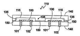
図1Bは、図1Aの断面A−Aにおけるヒータ100起動される液体金属マイクロスイッチ105の側面図の図面である。断面A−Aは、ヒータ100を通る平面に沿ってとられている。図1Bにおいて、ヒータ100は、マイクロ回路110を製造した基板140に取付けられている。対になった表面150においてシールされた蓋145は、液体金属マイクロスイッチ105を覆っている。電気的な接触は、それぞれのヒータ100への第1及び第2のヒータ接点101、102を介して、ヒータ100に行なわれる。前記のように、左側のヒータ100を通る電流は、左側の空洞115におけるガス135を膨張させる。この膨張は、ガスの一部が左側の補助通路125を介して主通路120に入るまで、継続している。
【0017】
図1Cは、図1Aの断面B−Bにおけるヒータ100起動される液体金属マイクロスイッチ105の側面図の図面である。断面B−Bは、主通路120を通る平面に沿ってとられている。右側におけるものよりも大きな容積を有する図1Cの左側における液体金属130は、液体金属マイクロスイッチ105の第1及び第2のマイクロスイッチ接点106、107を互いに電気的に短絡しているが、一方図1Cの右側における液体金属130の容積は一層小さく、図1Cの右側における第3のマイクロスイッチ接点108も、開いた回路を形成している。
【0018】
図2Aは、マイクロ回路110におけるヒータ100起動される液体金属マイクロスイッチ105の平面図の別の図面である。図2Aは、左側ヒータ100が起動された直後における液体金属マイクロスイッチ105の状態を示している。この状態において、左側の空洞115におけるガス135は、主通路120と左側補助通路125との間の境界面において、主通路120の左側における液体金属130の一部を主通路120の右側に向かって強制し始めるためにちょうど十分であるように加熱されている。
【0019】
図2Bは、マイクロ回路110におけるヒータ100起動される液体金属マイクロスイッチ105の平面図のさらに別の図面である。図2Bは、左側ヒータ100がさらに完全に起動された後における液体金属マイクロスイッチ105の状態を示している。この状態において、左側の空洞115におけるガス135は、初めに主通路120の左側にあった液体金属130の一部を主通路120の右側に強制するために十分に加熱されている。
【0020】
図2Cは、図2Bの断面C−Cにおけるヒータ100起動される液体金属マイクロスイッチ105の側面図である。断面C−Cは、主通路120を通る平面に沿ってとられている。この時、図2Cの右側における液体金属130は、液体金属マイクロスイッチ105の第2及び第3のマイクロスイッチ接点107、108を電気的に短絡するが、一方図2Cの左側における第1のマイクロスイッチ接点106は、この時、開いた回路を形成している。
【0021】
図3は、ヒータ100起動される液体金属マイクロスイッチ105の一部の平面図の図面である。ガス135を分離するための装置330は、ヒータ100及び補助通路125を含む。図3において、例えばモノリシック集積回路100であることができるヒータ100は、空洞115内に配置されている。空洞115は、補助通路125を介して主通路120に接続されている。主通路120は、典型的には水銀130である液体金属130によって部分的に満たされている。補助通路125は、補助通路125内に双頭矢印によって図3に示された横断面積300を有する。補助通路125と空洞115との間の境界面における横断面積300は、第1の値301を有し、かつ補助通路125と主通路120との間の境界面における横断面積300は、第2の値302を有する。図3において、第1の値301と第2の値302は等しい。このようにヒータが疑似平衡状態に達したとき、補助通路125と主通路120との境界面において補助通路125から出るガスの速度は、補助通路125と空洞115との間の境界面において補助通路125内に入るガス135の速度に等しい。ガス135の流れ305の方向は、図3における矢印の方向によって示されている。
【0022】
図4は、別の実施態様であるヒータ100によって駆動される液体金属マイクロスイッチ105の一部の平面図である。ガス135を分離するための装置330は、例えばモノリシック集積回路100であることができるヒータ100、及び補助通路125を含んでいる。図4において、ヒータ100は空洞115内に配置されている。空洞115は、補助通路125を介して主通路120に接続されている。主通路120は、典型的には水銀130である液体金属130によって部分的に満たされている。補助通路125は、補助通路125内に双頭矢印によって図4に示された横断面積300を有する。補助通路125と空洞115との間の境界面における横断面積300は、再び第1の値301を有し、かつ補助通路125と主通路120との間の境界面における横断面積300は、第2の値302を有する。図4において、第1の値301は、第2の値302より大きい。さらに図4において、横断面積300の値は、補助通路125と空洞115との間の境界面における第1の値301から補助通路125と主通路120との間の境界面における第2の値302まで、直線的に減少する。このようにヒータが疑似平衡状態に達したとき、補助通路125と主通路120との境界面において補助通路125から出るガスの速度は、補助通路125と空洞115との間の境界面において補助通路125内に入るガス135の速度より速い。ガス135の流れ305の方向は、図4における矢印の方向によって示されている。
【0023】
図5は、さらに別の実施態様に基づくヒータ100によって駆動される液体金属マイクロスイッチ105の一部の平面図である。ガス135を分離するための装置330は、例えばモノリシック集積回路100であるヒータ100、及び補助通路125を含んでいる。図5において、ヒータ100は空洞115内に配置されている。空洞115は、補助通路125を介して主通路120に接続されている。主通路120は、典型的には水銀130である液体金属130によって部分的に満たされている。補助通路125は、補助通路125内に双頭矢印によって図5に示された横断面積300を有する。補助通路125と空洞115との間の境界面における横断面積300は、第1の値301を有し、かつ補助通路125と主通路120との間の境界面における横断面積300は、第2の値302を有する。図5において、第1の値301は、第2の値302より大きい。さらに図5において、補助通路125及び空洞115の間の境界面と補助通路125及び主通路120の間の境界面との間に、位置310が配置されている。補助通路125の横断面積300の値は、補助通路125と空洞115との間の境界面から位置310まで第1の値301に維持されている。補助通路125の横断面積300の値は、位置310から補助通路125と主通路120との間の境界面まで第2の値302に維持されている。このようにヒータが疑似平衡状態に達したとき、補助通路125と主通路120との境界面において補助通路125から出るガスの速度は、補助通路125と空洞115との間の境界面において補助通路125内に入るガス135の速度より速い。ガス135の流れ305の方向は、図5における矢印の方向によって示されている。図5の補助通路125の幾何学的構造は、図4のものより容易にかつわずかな費用で製造される。
【0024】
マイクロ回路110における空洞115から主通路120にガス135を伝達するための補助通路125に関する本実施形態が従来技術に比べた利点は、補助通路125から出てかつ主通路120に入る際のガス135の速度が速くなる点にある。この速度の増加の結果、液体金属130の一層急速な分離が生じ、かつ主通路120の壁に対する応力が小さくなるとともに主通路120内に生じる熱が小さくなる。この時、主通路120の表面のぬれの増加する速度が、図3のものより低いので、液体金属マクロスイッチ105の寿命は増加する。
【0025】
本発明をその有利な実施例に関連して詳細に説明したが、一方記載した実施態様は、例として提供されており、かつ限定として提供されたものではない。記載した実施態様の形及び細部に種々の変更を行なうことができ、その結果、添付の特許請求の範囲の権利範囲内に含まれる均等な実施形態が生じることは、当業者にとって明らかであろう。
【0026】
最後に、本発明の代表的な実施態様をまとめて示す。
(実施態様1)
液体金属マイクロスイッチ(105)の中の液体(130)を分離する装置(330)において、
前記ヒータ(100)が、前記液体金属マイクロスイッチ(105)が製造される構造の空洞(115)の内側に配置されており、
主通路(120)に空洞(115)を接続するように前記構造の内側に設けられた補助通路(125)であって、前記補助通路(125)が横断面積(300)を有し、前記補助通路(125)と前記主通路(120)との間の境界における前記横断面積(300)の値が、前記補助通路(125)と前記空洞(115)との間の境界における前記横断面積(300)の値より小さく、ガス(135)が前記空洞(115)及び前記補助通路(125)に充満し、前記ガス(135)が前記主通路(120)内に達することができる補助通路(125)を有することを特徴とする、液体金属マイクロスイッチ(105)において液体(130)を分離する装置(330)。
【0027】
(実施態様2)
前記ヒータ(100)がモノリシックヒータ(100)であることを特徴とする実施態様1に記載の装置(330)。
【0028】
(実施態様3)
前記装置(330)が、厚膜マイクロ回路(110)の一部であることを特徴とする実施態様1に記載の装置(330)。
【0029】
(実施態様4)
前記補助通路(125)と前記空洞(115)との間の前記境界における前記横断面積(300)が、第1の値(301)を有し、
前記補助通路(125)と前記主通路(120)との間の前記境界における前記横断面積(300)が、第2の値(302)を有し、
前記補助通路(125)の前記横断面積(300)が、前記補助通路(125)及び前記空洞(115)の間の前記境界と、前記補助通路(125)及び前記空洞(115)の間の前記境界及び前記補助通路(125)及び前記主通路(120)の間の前記境界の間の所定のされた位置(310)との間において、前記第1の値(301)に維持されており、かつ、
前記補助通路(125)の前記横断面積(300)が、前記所定の位置(310)から、前記補助通路(125)と前記主通路(120)との間の前記境界まで、前記第2の値(302)に維持されることを特徴とする、実施態様1に記載の装置(330)。
【0030】
(実施態様5)
前記横断面積(300)が、前記補助通路(125)と前記空洞(115)との間の前記境界における前記横断面積から、前記補助通路(125)と前記主通路(120)との間の前記境界における前記横断面積まで、直線的に減少することを特徴とする、実施態様1に記載の装置(330)。
【図面の簡単な説明】
【図1A】マイクロ回路におけるヒータ起動される液体金属マイクロスイッチの平面図である。
【図1B】図1Aの断面A−Aにおけるヒータ駆動される液体金属マイクロスイッチの側面図である。
【図1C】図1Aの断面B−Bにおけるヒータ駆動される液体金属マイクロスイッチの側面図である。
【図2A】マイクロ回路におけるヒータ駆動される液体金属マイクロスイッチの別の平面図である。
【図2B】マイクロ回路におけるヒータ駆動される液体金属マイクロスイッチのさらに別の平面図である。
【図2C】図2Bの断面C−Cにおけるヒータ駆動される液体金属マイクロスイッチの側面図である。
【図3】ヒータ駆動される液体金属マイクロスイッチの一部の平面図である。
【図4】別の実施形態におけるヒータ駆動される液体金属マイクロスイッチの一部の平面図である。
【図5】さらに別の実施形態におけるヒータ駆動される液体金属マイクロスイッチの一部の平面図である。
【符号の説明】
100 ヒータ
105 マイクロスイッチ
110 マイクロ回路
115 空洞
120 主通路
125 補助通路
130 液体
135 ガス
300 横断面積
301 第1の値
302 第2の値
310 位置
330 装置[0001]
TECHNICAL FIELD OF THE INVENTION
The present invention relates generally to the field of microwave circuits, and more particularly to integrated thick film radio frequency and microwave microcircuit modules, and even more particularly to microswitches and heaters in such modules. .
[0002]
[Prior art]
Electronic circuits of all construction types typically have a need for switches and relays. A typical compact mechanical contact type relay is a reed relay. The reed relay includes a reed switch. In the reed switch, two reeds made of a magnetic alloy are accommodated inside a small glass container together with an inert gas. The coil for electromagnetic drive is wound around a reed switch, and the two reeds are installed either in contact or non-contact in a glass container.
[0003]
Reed relays include dry reed relays and wet reed relays. Normally, a dry reed relay is used, and the ends (contacts) of the leads are made of silver, tungsten, rhodium, or an alloy containing any of these, and the surfaces of the contacts are plated with rhodium, gold or the like. At the contacts of dry reed relays, the contact resistance is high and there is considerable wear on the contacts. Various attempts have been made to treat the surface of these contacts, as reliability is reduced if the contact resistance is high at the contacts, or if there is significant wear on the contacts.
[0004]
Contact reliability can be enhanced by utilizing mercury with wet reed relays. In particular, by covering the contact surfaces of the leads with mercury, the contact resistance at the contacts is reduced and the wear of the contacts is reduced, resulting in improved reliability. In addition, the reed's switching behavior involves mechanical fatigue due to bending, so the reed may begin to malfunction after several years of use.
[0005]
A newer type of switch mechanism is configured such that a plurality of electrodes are exposed at specific locations along the inner wall of the elongated, electrically isolated passage. This passage is filled with a small volume of electrically conducting liquid to form a short liquid column. When the two electrodes are to be closed electrically, the liquid column is moved to a position where it contacts both electrodes simultaneously. When trying to open the two electrodes, the liquid column is moved to a position that does not contact both electrodes at the same time.
[0006]
In order to move a liquid column, U.S. Pat. No. 6,037,086 discloses generating a pressure difference across the liquid column. The pressure difference is created by changing the volume of a gas compartment located on either side of the liquid column, such as by a diaphragm.
[0007]
In another development, U.S. Pat. Nos. 5,059,009 and 5,069,064 disclose that a heater is provided in the gas compartment to create a pressure differential across the liquid column. The heater heats the gas in a gas compartment located on one side of the liquid column. The technique disclosed in Patent Document 3 (related to a micro relay element) can also be applied to an integrated circuit. Other aspects are described in Non-Patent Document 1 in J. Discussed by Simon et al. The disclosure is disclosed in Patent Document 4 entitled "Electrical Contact Breaker Switch, Integrated Electrical Contact Breaker Switch, and Electrical Contact Switching Method". It is also performed by Kondo and others.
[0008]
[Patent Document 1]
JP-A-47-21645 [Patent Document 2]
JP-B-36-18575 [Patent Document 3]
JP-A-9-161640 [Patent Document 4]
US Patent No. 6,323,447 [Non-Patent Document 1]
J. Simon et al., Paper "A Liquid-Filled Microrelay with a Moving Mercury Drop", "Journal of Microelectromechanical Systems", Vol. 6, No. 3, September 1997, 0009
[Problems to be solved by the invention]
The speed of operation, the power requirements for the switch, and the reliability of the switch are all important issues for such a switch. Repeated switch cycles have been found to result in short circuits. A possible cause for these short circuits is the increased wetting of the material surface by mercury caused by the formation of microcracks in the material as the switch material is repeatedly exposed to high temperatures. Accordingly, it would be advantageous to provide a technique for reducing the amount of heat dissipated to the wall of material surrounding the liquid metal while increasing the speed of the switch.
[0010]
[Means for Solving the Problems]
The liquid metal microswitch has a heater and an auxiliary passage inside. The heater is located inside the cavity. An inner auxiliary passage connects the cavity and the main passage. The auxiliary passage has a predetermined cross-sectional area. The value of the cross-sectional area at the boundary between the auxiliary passage and the main passage is smaller than the value of the cross-sectional area at the boundary between the auxiliary passage and the cavity. The gas fills the cavities and auxiliary passages and reaches the main passages.
[0011]
The applications and advantages of the present invention will become apparent from the accompanying drawings and detailed description.
[0012]
The accompanying drawings provide a visual representation for a better understanding of the invention, and the invention and its inherent advantages may be utilized to facilitate a person of ordinary skill in the art. In these drawings, like reference numbers indicate corresponding elements.
[0013]
BEST MODE FOR CARRYING OUT THE INVENTION
As shown in the drawings for purposes of illustration, the present patent specification relates to techniques for providing gas flow in a heater driven liquid metal microswitch in a microcircuit. By providing a gas flow that drives the liquid metal in the passage of the microswitch, heat dissipation in the passage is reduced, microcracking and passage surface wetting are reduced, and switch life is increased.
[0014]
In the following detailed description and several figures of the drawings, similar elements are identified by similar reference numerals.
[0015]
FIG. 1A is a plan view of the
[0016]
FIG. 1B is a side view drawing of the
[0017]
FIG. 1C is a side view drawing of the
[0018]
FIG. 2A is another plan view of the
[0019]
FIG. 2B is yet another plan view of the
[0020]
FIG. 2C is a side view of the
[0021]
FIG. 3 is a plan view of a part of the liquid metal
[0022]
FIG. 4 is a plan view of a part of a liquid metal
[0023]
FIG. 5 is a plan view of a portion of a
[0024]
An advantage of this embodiment over the prior art regarding the
[0025]
Although the invention has been described in detail with reference to its advantageous embodiments, the described embodiments are provided by way of example and not by way of limitation. It will be apparent to those skilled in the art that various changes can be made in the form and detail of the described embodiments, resulting in equivalent embodiments that fall within the scope of the appended claims. .
[0026]
Finally, representative embodiments of the present invention are summarized.
(Embodiment 1)
An apparatus (330) for separating a liquid (130) in a liquid metal microswitch (105),
Said heater (100) is located inside a cavity (115) of a structure in which said liquid metal microswitch (105) is manufactured;
An auxiliary passage (125) provided inside the structure to connect the cavity (115) to the main passage (120), the auxiliary passage (125) having a cross-sectional area (300); The value of the cross-sectional area (300) at the boundary between the passage (125) and the main passage (120) is equal to the value of the cross-sectional area (300) at the boundary between the auxiliary passage (125) and the cavity (115). ), The gas (135) fills the cavity (115) and the auxiliary passage (125) so that the gas (135) can reach into the main passage (120). An apparatus (330) for separating a liquid (130) in a liquid metal microswitch (105), comprising:
[0027]
(Embodiment 2)
The apparatus (330) of claim 1, wherein the heater (100) is a monolithic heater (100).
[0028]
(Embodiment 3)
The device (330) of embodiment 1, wherein the device (330) is part of a thick film microcircuit (110).
[0029]
(Embodiment 4)
The cross-sectional area (300) at the boundary between the auxiliary passage (125) and the cavity (115) has a first value (301);
The cross-sectional area (300) at the boundary between the auxiliary passage (125) and the main passage (120) has a second value (302);
The cross-sectional area (300) of the auxiliary passage (125) is defined by the boundary between the auxiliary passage (125) and the cavity (115) and the boundary between the auxiliary passage (125) and the cavity (115). A first value (301) between a boundary and a predetermined position (310) between the auxiliary passage (125) and the boundary between the main passage (120); And,
The second value of the cross-sectional area (300) of the auxiliary passage (125) from the predetermined position (310) to the boundary between the auxiliary passage (125) and the main passage (120). Apparatus (330) according to embodiment 1, characterized in that it is maintained at (302).
[0030]
(Embodiment 5)
The cross-sectional area (300) determines the distance between the auxiliary passage (125) and the main passage (120) from the cross-sectional area at the boundary between the auxiliary passage (125) and the cavity (115). Apparatus (330) according to embodiment 1, characterized in that it decreases linearly up to the cross-sectional area at the boundary.
[Brief description of the drawings]
FIG. 1A is a plan view of a heater-activated liquid metal microswitch in a microcircuit.
FIG. 1B is a side view of the heater driven liquid metal microswitch in section AA of FIG. 1A.
FIG. 1C is a side view of the heater driven liquid metal microswitch in section BB of FIG. 1A.
FIG. 2A is another plan view of a heater driven liquid metal microswitch in a microcircuit.
FIG. 2B is yet another plan view of a heater driven liquid metal microswitch in a microcircuit.
FIG. 2C is a side view of the heater driven liquid metal microswitch in section CC of FIG. 2B.
FIG. 3 is a plan view of a part of a liquid metal micro switch driven by a heater.
FIG. 4 is a plan view of a portion of a heater driven liquid metal microswitch in another embodiment.
FIG. 5 is a plan view of a portion of a heater driven liquid metal microswitch in yet another embodiment.
[Explanation of symbols]
100
Claims (5)
前記ヒータ(100)が、前記液体金属マイクロスイッチ(105)が製造される構造の空洞(115)の内側に配置されており、
主通路(120)に空洞(115)を接続するように前記構造の内側に設けられた補助通路(125)であって、前記補助通路(125)が横断面積(300)を有し、前記補助通路(125)と前記主通路(120)との間の境界における前記横断面積(300)の値が、前記補助通路(125)と前記空洞(115)との間の境界における前記横断面積(300)の値より小さく、ガス(135)が前記空洞(115)及び前記補助通路(125)に充満し、前記ガス(135)が前記主通路(120)内に達することができる補助通路(125)を有することを特徴とする、液体金属マイクロスイッチ(105)において液体(130)を分離する装置(330)。An apparatus (330) for separating a liquid (130) in a liquid metal microswitch (105),
Said heater (100) is located inside a cavity (115) of a structure in which said liquid metal microswitch (105) is manufactured;
An auxiliary passage (125) provided inside the structure to connect the cavity (115) to the main passage (120), the auxiliary passage (125) having a cross-sectional area (300); The value of the cross-sectional area (300) at the boundary between the passage (125) and the main passage (120) is equal to the value of the cross-sectional area (300) at the boundary between the auxiliary passage (125) and the cavity (115). ), The gas (135) fills the cavity (115) and the auxiliary passage (125) so that the gas (135) can reach into the main passage (120). An apparatus (330) for separating a liquid (130) in a liquid metal microswitch (105), comprising:
前記補助通路(125)と前記主通路(120)との間の前記境界における前記横断面積(300)が、第2の値(302)を有し、
前記補助通路(125)の前記横断面積(300)が、前記補助通路(125)及び前記空洞(115)の間の前記境界と、前記補助通路(125)及び前記空洞(115)の間の前記境界及び前記補助通路(125)及び前記主通路(120)の間の前記境界の間の所定のされた位置(310)との間において、前記第1の値(301)に維持されており、かつ、
前記補助通路(125)の前記横断面積(300)が、前記所定の位置(310)から、前記補助通路(125)と前記主通路(120)との間の前記境界まで、前記第2の値(302)に維持されることを特徴とする、請求項1に記載の装置(330)。The cross-sectional area (300) at the boundary between the auxiliary passage (125) and the cavity (115) has a first value (301);
The cross-sectional area (300) at the boundary between the auxiliary passage (125) and the main passage (120) has a second value (302);
The cross-sectional area (300) of the auxiliary passage (125) is defined by the boundary between the auxiliary passage (125) and the cavity (115) and the boundary between the auxiliary passage (125) and the cavity (115). A first value (301) between a boundary and a predetermined position (310) between the auxiliary passage (125) and the boundary between the main passage (120); And,
The second value of the cross-sectional area (300) of the auxiliary passage (125) from the predetermined position (310) to the boundary between the auxiliary passage (125) and the main passage (120). Apparatus (330) according to claim 1, characterized in that it is maintained at (302).
Applications Claiming Priority (1)
| Application Number | Priority Date | Filing Date | Title |
|---|---|---|---|
| US10/192,408 US6559420B1 (en) | 2002-07-10 | 2002-07-10 | Micro-switch heater with varying gas sub-channel cross-section |
Publications (2)
| Publication Number | Publication Date |
|---|---|
| JP2004055549A true JP2004055549A (en) | 2004-02-19 |
| JP2004055549A5 JP2004055549A5 (en) | 2006-07-20 |
Family
ID=22709517
Family Applications (1)
| Application Number | Title | Priority Date | Filing Date |
|---|---|---|---|
| JP2003190322A Pending JP2004055549A (en) | 2002-07-10 | 2003-07-02 | Liquid separator in liquid metal microswitch |
Country Status (2)
| Country | Link |
|---|---|
| US (1) | US6559420B1 (en) |
| JP (1) | JP2004055549A (en) |
Families Citing this family (84)
| Publication number | Priority date | Publication date | Assignee | Title |
|---|---|---|---|---|
| US6689976B1 (en) * | 2002-10-08 | 2004-02-10 | Agilent Technologies, Inc. | Electrically isolated liquid metal micro-switches for integrally shielded microcircuits |
| US7078849B2 (en) * | 2001-10-31 | 2006-07-18 | Agilent Technologies, Inc. | Longitudinal piezoelectric optical latching relay |
| AU2002365151A1 (en) * | 2001-11-07 | 2003-07-09 | The Board Of Trustees Of The University Of Arkansas | Structure and process for packaging rf mems and other devices |
| US6741767B2 (en) * | 2002-03-28 | 2004-05-25 | Agilent Technologies, Inc. | Piezoelectric optical relay |
| US20030194170A1 (en) * | 2002-04-10 | 2003-10-16 | Wong Marvin Glenn | Piezoelectric optical demultiplexing switch |
| US6927529B2 (en) | 2002-05-02 | 2005-08-09 | Agilent Technologies, Inc. | Solid slug longitudinal piezoelectric latching relay |
| US6750594B2 (en) | 2002-05-02 | 2004-06-15 | Agilent Technologies, Inc. | Piezoelectrically actuated liquid metal switch |
| US6756551B2 (en) | 2002-05-09 | 2004-06-29 | Agilent Technologies, Inc. | Piezoelectrically actuated liquid metal switch |
| US6774324B2 (en) * | 2002-12-12 | 2004-08-10 | Agilent Technologies, Inc. | Switch and production thereof |
| US6743990B1 (en) * | 2002-12-12 | 2004-06-01 | Agilent Technologies, Inc. | Volume adjustment apparatus and method for use |
| US6855898B2 (en) * | 2002-12-12 | 2005-02-15 | Agilent Technologies, Inc. | Ceramic channel plate for a switch |
| US7022926B2 (en) * | 2002-12-12 | 2006-04-04 | Agilent Technologies, Inc. | Ultrasonically milled channel plate for a switch |
| US20040112727A1 (en) * | 2002-12-12 | 2004-06-17 | Wong Marvin Glenn | Laser cut channel plate for a switch |
| US6787719B2 (en) * | 2002-12-12 | 2004-09-07 | Agilent Technologies, Inc. | Switch and method for producing the same |
| US7019235B2 (en) * | 2003-01-13 | 2006-03-28 | Agilent Technologies, Inc. | Photoimaged channel plate for a switch |
| US6809277B2 (en) * | 2003-01-22 | 2004-10-26 | Agilent Technologies, Inc. | Method for registering a deposited material with channel plate channels, and switch produced using same |
| US6747222B1 (en) * | 2003-02-04 | 2004-06-08 | Agilent Technologies, Inc. | Feature formation in a nonphotoimagable material and switch incorporating same |
| EP1460740B1 (en) * | 2003-03-20 | 2006-06-07 | Agilent Technologies, Inc. - a Delaware corporation - | An optoelectronic module and a thermal switch therefor |
| US6825429B2 (en) * | 2003-03-31 | 2004-11-30 | Agilent Technologies, Inc. | Hermetic seal and controlled impedance RF connections for a liquid metal micro switch |
| US6879088B2 (en) * | 2003-04-14 | 2005-04-12 | Agilent Technologies, Inc. | Insertion-type liquid metal latching relay array |
| US6879089B2 (en) * | 2003-04-14 | 2005-04-12 | Agilent Technologies, Inc. | Damped longitudinal mode optical latching relay |
| US6903493B2 (en) * | 2003-04-14 | 2005-06-07 | Agilent Technologies, Inc. | Inserting-finger liquid metal relay |
| US6906271B2 (en) * | 2003-04-14 | 2005-06-14 | Agilent Technologies, Inc. | Fluid-based switch |
| US6831532B2 (en) * | 2003-04-14 | 2004-12-14 | Agilent Technologies, Inc. | Push-mode latching relay |
| US6924443B2 (en) * | 2003-04-14 | 2005-08-02 | Agilent Technologies, Inc. | Reducing oxides on a switching fluid in a fluid-based switch |
| US6956990B2 (en) * | 2003-04-14 | 2005-10-18 | Agilent Technologies, Inc. | Reflecting wedge optical wavelength multiplexer/demultiplexer |
| US6946776B2 (en) * | 2003-04-14 | 2005-09-20 | Agilent Technologies, Inc. | Method and apparatus for maintaining a liquid metal switch in a ready-to-switch condition |
| US6903492B2 (en) * | 2003-04-14 | 2005-06-07 | Agilent Technologies, Inc. | Wetting finger latching piezoelectric relay |
| US6891116B2 (en) * | 2003-04-14 | 2005-05-10 | Agilent Technologies, Inc. | Substrate with liquid electrode |
| US6891315B2 (en) * | 2003-04-14 | 2005-05-10 | Agilent Technologies, Inc. | Shear mode liquid metal switch |
| US6765161B1 (en) * | 2003-04-14 | 2004-07-20 | Agilent Technologies, Inc. | Method and structure for a slug caterpillar piezoelectric latching reflective optical relay |
| US6803842B1 (en) | 2003-04-14 | 2004-10-12 | Agilent Technologies, Inc. | Longitudinal mode solid slug optical latching relay |
| US7071432B2 (en) * | 2003-04-14 | 2006-07-04 | Agilent Technologies, Inc. | Reduction of oxides in a fluid-based switch |
| US6882088B2 (en) * | 2003-04-14 | 2005-04-19 | Agilent Technologies, Inc. | Bending-mode latching relay |
| US6774325B1 (en) | 2003-04-14 | 2004-08-10 | Agilent Technologies, Inc. | Reducing oxides on a switching fluid in a fluid-based switch |
| US6762378B1 (en) | 2003-04-14 | 2004-07-13 | Agilent Technologies, Inc. | Liquid metal, latching relay with face contact |
| US6876130B2 (en) * | 2003-04-14 | 2005-04-05 | Agilent Technologies, Inc. | Damped longitudinal mode latching relay |
| US6920259B2 (en) * | 2003-04-14 | 2005-07-19 | Agilent Technologies, Inc. | Longitudinal electromagnetic latching optical relay |
| US6794591B1 (en) | 2003-04-14 | 2004-09-21 | Agilent Technologies, Inc. | Fluid-based switches |
| US6894237B2 (en) * | 2003-04-14 | 2005-05-17 | Agilent Technologies, Inc. | Formation of signal paths to increase maximum signal-carrying frequency of a fluid-based switch |
| US6961487B2 (en) * | 2003-04-14 | 2005-11-01 | Agilent Technologies, Inc. | Method and structure for a pusher-mode piezoelectrically actuated liquid metal optical switch |
| US7012354B2 (en) * | 2003-04-14 | 2006-03-14 | Agilent Technologies, Inc. | Method and structure for a pusher-mode piezoelectrically actuated liquid metal switch |
| US6838959B2 (en) * | 2003-04-14 | 2005-01-04 | Agilent Technologies, Inc. | Longitudinal electromagnetic latching relay |
| US6841746B2 (en) * | 2003-04-14 | 2005-01-11 | Agilent Technologies, Inc. | Bent switching fluid cavity |
| US6798937B1 (en) | 2003-04-14 | 2004-09-28 | Agilent Technologies, Inc. | Pressure actuated solid slug optical latching relay |
| US6740829B1 (en) | 2003-04-14 | 2004-05-25 | Agilent Technologies, Inc. | Insertion-type liquid metal latching relay |
| US6888977B2 (en) * | 2003-04-14 | 2005-05-03 | Agilent Technologies, Inc. | Polymeric liquid metal optical switch |
| US7048519B2 (en) * | 2003-04-14 | 2006-05-23 | Agilent Technologies, Inc. | Closed-loop piezoelectric pump |
| US6925223B2 (en) * | 2003-04-14 | 2005-08-02 | Agilent Technologies, Inc. | Pressure actuated optical latching relay |
| US6818844B2 (en) * | 2003-04-14 | 2004-11-16 | Agilent Technologies, Inc. | Method and structure for a slug assisted pusher-mode piezoelectrically actuated liquid metal optical switch |
| US6768068B1 (en) | 2003-04-14 | 2004-07-27 | Agilent Technologies, Inc. | Method and structure for a slug pusher-mode piezoelectrically actuated liquid metal switch |
| US7070908B2 (en) * | 2003-04-14 | 2006-07-04 | Agilent Technologies, Inc. | Feature formation in thick-film inks |
| US6894424B2 (en) * | 2003-04-14 | 2005-05-17 | Agilent Technologies, Inc. | High frequency push-mode latching relay |
| US6876131B2 (en) * | 2003-04-14 | 2005-04-05 | Agilent Technologies, Inc. | High-frequency, liquid metal, latching relay with face contact |
| US6903490B2 (en) * | 2003-04-14 | 2005-06-07 | Agilent Technologies, Inc. | Longitudinal mode optical latching relay |
| US6885133B2 (en) * | 2003-04-14 | 2005-04-26 | Agilent Technologies, Inc. | High frequency bending-mode latching relay |
| US6903287B2 (en) * | 2003-04-14 | 2005-06-07 | Agilent Technologies, Inc. | Liquid metal optical relay |
| US6946775B2 (en) * | 2003-04-14 | 2005-09-20 | Agilent Technologies, Inc. | Method and structure for a slug assisted longitudinal piezoelectrically actuated liquid metal optical switch |
| US6876133B2 (en) * | 2003-04-14 | 2005-04-05 | Agilent Technologies, Inc. | Latching relay with switch bar |
| US6900578B2 (en) * | 2003-04-14 | 2005-05-31 | Agilent Technologies, Inc. | High frequency latching relay with bending switch bar |
| US6730866B1 (en) | 2003-04-14 | 2004-05-04 | Agilent Technologies, Inc. | High-frequency, liquid metal, latching relay array |
| US6770827B1 (en) | 2003-04-14 | 2004-08-03 | Agilent Technologies, Inc. | Electrical isolation of fluid-based switches |
| US6816641B2 (en) * | 2003-04-14 | 2004-11-09 | Agilent Technologies, Inc. | Method and structure for a solid slug caterpillar piezoelectric optical relay |
| US6876132B2 (en) * | 2003-04-14 | 2005-04-05 | Agilent Technologies, Inc. | Method and structure for a solid slug caterpillar piezoelectric relay |
| US20040201447A1 (en) * | 2003-04-14 | 2004-10-14 | Wong Marvin Glenn | Thin-film resistor device |
| US6870111B2 (en) * | 2003-04-14 | 2005-03-22 | Agilent Technologies, Inc. | Bending mode liquid metal switch |
| US6750413B1 (en) | 2003-04-25 | 2004-06-15 | Agilent Technologies, Inc. | Liquid metal micro switches using patterned thick film dielectric as channels and a thin ceramic or glass cover plate |
| US6777630B1 (en) | 2003-04-30 | 2004-08-17 | Agilent Technologies, Inc. | Liquid metal micro switches using as channels and heater cavities matching patterned thick film dielectric layers on opposing thin ceramic plates |
| US6759610B1 (en) | 2003-06-05 | 2004-07-06 | Agilent Technologies, Inc. | Multi-layer assembly of stacked LIMMS devices with liquid metal vias |
| US6833520B1 (en) * | 2003-06-16 | 2004-12-21 | Agilent Technologies, Inc. | Suspended thin-film resistor |
| US6759611B1 (en) | 2003-06-16 | 2004-07-06 | Agilent Technologies, Inc. | Fluid-based switches and methods for producing the same |
| US6781074B1 (en) | 2003-07-30 | 2004-08-24 | Agilent Technologies, Inc. | Preventing corrosion degradation in a fluid-based switch |
| US6787720B1 (en) | 2003-07-31 | 2004-09-07 | Agilent Technologies, Inc. | Gettering agent and method to prevent corrosion in a fluid switch |
| US20050030347A1 (en) * | 2003-08-08 | 2005-02-10 | Sasko Zarev | Concentric curvilinear heater resistor |
| US6822176B1 (en) * | 2004-04-16 | 2004-11-23 | Agilent Technologies, Inc. | Liquid metal switch and method of manufacture therefor |
| US7132614B2 (en) * | 2004-11-24 | 2006-11-07 | Agilent Technologies, Inc. | Liquid metal switch employing electrowetting for actuation and architectures for implementing same |
| US7030328B1 (en) | 2004-12-22 | 2006-04-18 | Agilent Technologies, Inc. | Liquid metal switch employing micro-electromechanical system (MEMS) structures for actuation |
| US7164090B2 (en) * | 2005-02-28 | 2007-01-16 | Agilent Technologies, Inc. | Liquid metal switch employing a single volume of liquid metal |
| US7158363B2 (en) * | 2005-04-11 | 2007-01-02 | Agilent Technologies, Inc. | Liquid metal varactor and method |
| US7358452B2 (en) * | 2005-06-30 | 2008-04-15 | Agilent Technlolgies, Inc. | Architecture and method of fabrication for a liquid metal microswitch (LIMMS) |
| US8362376B2 (en) * | 2007-01-19 | 2013-01-29 | The Regents Of The University Of California | Electrostatically driven high speed micro droplet switch |
| JP2009117078A (en) * | 2007-11-02 | 2009-05-28 | Yokogawa Electric Corp | Relay |
| US10760985B2 (en) * | 2018-06-26 | 2020-09-01 | Tdk Corporation | Smart surface sensor for collecting data |
| US10866036B1 (en) | 2020-05-18 | 2020-12-15 | Envertic Thermal Systems, Llc | Thermal switch |
Family Cites Families (10)
| Publication number | Priority date | Publication date | Assignee | Title |
|---|---|---|---|---|
| US4103135A (en) * | 1976-07-01 | 1978-07-25 | International Business Machines Corporation | Gas operated switches |
| US4419650A (en) * | 1979-08-23 | 1983-12-06 | Georgina Chrystall Hirtle | Liquid contact relay incorporating gas-containing finely reticular solid motor element for moving conductive liquid |
| US4628161A (en) * | 1985-05-15 | 1986-12-09 | Thackrey James D | Distorted-pool mercury switch |
| US4652710A (en) * | 1986-04-09 | 1987-03-24 | The United States Of America As Represented By The United States Department Of Energy | Mercury switch with non-wettable electrodes |
| US4797519A (en) * | 1987-04-17 | 1989-01-10 | Elenbaas George H | Mercury tilt switch and method of manufacture |
| US5751074A (en) * | 1995-09-08 | 1998-05-12 | Edward B. Prior & Associates | Non-metallic liquid tilt switch and circuitry |
| US5912606A (en) * | 1998-08-18 | 1999-06-15 | Northrop Grumman Corporation | Mercury wetted switch |
| US6373356B1 (en) * | 1999-05-21 | 2002-04-16 | Interscience, Inc. | Microelectromechanical liquid metal current carrying system, apparatus and method |
| US6396012B1 (en) * | 1999-06-14 | 2002-05-28 | Rodger E. Bloomfield | Attitude sensing electrical switch |
| US6512322B1 (en) * | 2001-10-31 | 2003-01-28 | Agilent Technologies, Inc. | Longitudinal piezoelectric latching relay |
-
2002
- 2002-07-10 US US10/192,408 patent/US6559420B1/en not_active Expired - Fee Related
-
2003
- 2003-07-02 JP JP2003190322A patent/JP2004055549A/en active Pending
Also Published As
| Publication number | Publication date |
|---|---|
| US6559420B1 (en) | 2003-05-06 |
Similar Documents
| Publication | Publication Date | Title |
|---|---|---|
| JP2004055549A (en) | Liquid separator in liquid metal microswitch | |
| KR20010030305A (en) | Folded spring based micro electromechanical RF switch and method of making | |
| US6689976B1 (en) | Electrically isolated liquid metal micro-switches for integrally shielded microcircuits | |
| US6900578B2 (en) | High frequency latching relay with bending switch bar | |
| US6730866B1 (en) | High-frequency, liquid metal, latching relay array | |
| US6831532B2 (en) | Push-mode latching relay | |
| US6894424B2 (en) | High frequency push-mode latching relay | |
| US6876133B2 (en) | Latching relay with switch bar | |
| US6885133B2 (en) | High frequency bending-mode latching relay | |
| US6762378B1 (en) | Liquid metal, latching relay with face contact | |
| JP2006040892A (en) | Metal contact electric switch incorporating lorentz actuator | |
| US6879088B2 (en) | Insertion-type liquid metal latching relay array | |
| JP2004047464A (en) | Suspended heater for liquid metal microswitch | |
| JP2004319498A (en) | Insertion type liquid metal latching relay | |
| JP2009026568A (en) | Switch device | |
| JP2004227858A (en) | Electric contact switching device and manufacturing method of electric contact switching device | |
| US20040201313A1 (en) | High-frequency, liquid metal, latching relay with face contact | |
| US6882088B2 (en) | Bending-mode latching relay | |
| JP2007066735A (en) | Electric contact switching device and method of manufacturing same |
Legal Events
| Date | Code | Title | Description |
|---|---|---|---|
| A521 | Request for written amendment filed |
Free format text: JAPANESE INTERMEDIATE CODE: A523 Effective date: 20060606 |
|
| A621 | Written request for application examination |
Free format text: JAPANESE INTERMEDIATE CODE: A621 Effective date: 20060606 |
|
| A131 | Notification of reasons for refusal |
Free format text: JAPANESE INTERMEDIATE CODE: A131 Effective date: 20080710 |
|
| A02 | Decision of refusal |
Free format text: JAPANESE INTERMEDIATE CODE: A02 Effective date: 20081218 |