EP1619523A1 - Optical lens and method of manufacturing the same - Google Patents
Optical lens and method of manufacturing the same Download PDFInfo
- Publication number
- EP1619523A1 EP1619523A1 EP05015660A EP05015660A EP1619523A1 EP 1619523 A1 EP1619523 A1 EP 1619523A1 EP 05015660 A EP05015660 A EP 05015660A EP 05015660 A EP05015660 A EP 05015660A EP 1619523 A1 EP1619523 A1 EP 1619523A1
- Authority
- EP
- European Patent Office
- Prior art keywords
- lens
- concave
- convex
- optical
- lens surface
- Prior art date
- Legal status (The legal status is an assumption and is not a legal conclusion. Google has not performed a legal analysis and makes no representation as to the accuracy of the status listed.)
- Withdrawn
Links
- 230000003287 optical effect Effects 0.000 title claims abstract description 159
- 238000004519 manufacturing process Methods 0.000 title claims description 21
- 230000000694 effects Effects 0.000 claims abstract description 14
- 238000000465 moulding Methods 0.000 claims description 40
- 238000001746 injection moulding Methods 0.000 claims description 20
- 238000000034 method Methods 0.000 description 19
- 238000005520 cutting process Methods 0.000 description 17
- 238000005259 measurement Methods 0.000 description 15
- 230000015572 biosynthetic process Effects 0.000 description 5
- 239000011347 resin Substances 0.000 description 5
- 229920005989 resin Polymers 0.000 description 5
- 238000010586 diagram Methods 0.000 description 2
- 239000000463 material Substances 0.000 description 2
- 239000012768 molten material Substances 0.000 description 2
- 229910000838 Al alloy Inorganic materials 0.000 description 1
- 229910000881 Cu alloy Inorganic materials 0.000 description 1
- 229910000831 Steel Inorganic materials 0.000 description 1
- 238000007796 conventional method Methods 0.000 description 1
- 238000001816 cooling Methods 0.000 description 1
- 238000003384 imaging method Methods 0.000 description 1
- 238000003825 pressing Methods 0.000 description 1
- 239000010959 steel Substances 0.000 description 1
Images







Classifications
-
- G—PHYSICS
- G02—OPTICS
- G02B—OPTICAL ELEMENTS, SYSTEMS OR APPARATUS
- G02B3/00—Simple or compound lenses
-
- B—PERFORMING OPERATIONS; TRANSPORTING
- B29—WORKING OF PLASTICS; WORKING OF SUBSTANCES IN A PLASTIC STATE IN GENERAL
- B29D—PRODUCING PARTICULAR ARTICLES FROM PLASTICS OR FROM SUBSTANCES IN A PLASTIC STATE
- B29D11/00—Producing optical elements, e.g. lenses or prisms
- B29D11/00009—Production of simple or compound lenses
-
- G—PHYSICS
- G02—OPTICS
- G02B—OPTICAL ELEMENTS, SYSTEMS OR APPARATUS
- G02B27/00—Optical systems or apparatus not provided for by any of the groups G02B1/00 - G02B26/00, G02B30/00
- G02B27/62—Optical apparatus specially adapted for adjusting optical elements during the assembly of optical systems
Definitions
- the present invention relates to an optical lens having a lens surface on each surface and a method of manufacturing the same, and more specifically, to an optical lens that is injection-molded by a mold and that has a convex portion or a concave portion in the center of both lens surfaces and a method of manufacturing the same.
- an injection-molding method is generally used, which is suitable for mass production at a low cost.
- upper and lower molds which are formed to correspond to the contour of a desired molded product are arranged to be opposed to each other, a molten material is injected into the space between the upper and lower molds to be cooled and solidified, and then a molding product is formed.
- a plurality of optical lens are generally arranged in the direction of the optical axis to constitute a lens system. Since the deviation between the central axes of the respective lenses becomes a cause of reduction in resolution, it is necessary that the respective lenses constituting the lens system should be arranged with high precision.
- the deviation between the central axes of the lenses can be adjusted by a piezoelectric element which is arranged in each of the lenses to be moved minutely.
- a piezoelectric element which is arranged in each of the lenses to be moved minutely.
- an eccentricity amount of a single lens is less than several micrometers.
- the difference between the virtual center calculated by the above-described method and the actual optical center easily occurs.
- the contour of the lens is easily distorted due to the flow of injected resin, so that an eccentricity amount_is hardly measured and adjusted with high precision.
- the present invention has been made in view of the above problems. It is therefore an object of the present invention to provide an optical lens which is molded by a mold and by which an amount of eccentricity between both lens surfaces can be measured and adjusted precisely with a simple method and a method of manufacturing the optical lens.
- an optical lens includes a lens portion having a convex or concave lens surface on each side.
- Each lens surface of the lens portion has a convex portion constituted by a small projection centered on the optical axis thereof, and the convex portion has the height which is approximately less than four times the used wavelength so as not to have an effect on an optical characteristic of the lens portion.
- an optical lens includes a lens portion having a convex or concave lens surface on each side.
- Each lens surface of the lens portion has a concave portion of a small hole centered on the optical axis thereof, the concave portion is formed in a substantially cylindrical shape or a substantially conical shape, and the diameter of the base is in the range of 0.5 to 5 ⁇ m.
- the convex portion is formed in a cross shape and the intersection of the cross shape is arranged on the optical axis of the lens surface.
- each lens surface of the lens portion has a concentric stepped portion centered on the concave portion or the convex portion in the vicinity of the concave portion or the convex portion.
- each lens surface of the lens portion has an orientation concave portion or an orientation convex portion at the position where both lens surfaces are opposed to each other in the vicinity of the concave portion or the convex portion.
- a plate-like edge portion is formed on the circumferential edge of the lens portion and, on both surfaces of the edge portion, a plurality of circumferential-edge convex portions are formed at the position corresponding thereto.
- a method of manufacturing an optical lens which is formed by upper and lower molds and includes a lens portion having a convex lens surface or a concave lens surface on each side, includes forming a lens surface molding portion which is constituted by a convex surface or a concave surface corresponding to the lens surface in each of the upper and lower molds and simultaneously, forming a small hole, which has the depth which is less than four times the used wavelength of the lens portion, the small hole being centered on the position corresponding to the optical axis of the lens surface; injection-molding the lens portion by use of the upper and lower molds on which the lens surface molding portion is formed; and based on the positional deviation between the respective convex portions formed on each lens surface by the small hole, adjusting the relative position between the upper and lower molds.
- a method of manufacturing an optical lens which is formed by upper and lower molds and includes a lens portion having a convex lens surface or a concave lens surface on each side, includes forming a lens surface molding portion which is constituted by a convex surface or a concave surface corresponding to the lens surface in each of the upper and lower molds and which has a small projection having a substantially cylindrical shape or substantially conical shape of which the base has the diameter in a range of 0.5 to 5 ⁇ m, the small projection being centered on the position corresponding to the optical axis of the lens surface; injection-molding the lens portion by use of the upper and lower molds on which the lens surface molding portion is formed; and based on the positional deviation between the respective concave portions formed on each lens surface by the small projection, adjusting the relative position between the upper and lower molds.
- Fig. 1 is a perspective view of an optical lens 1 in the present embodiment
- Fig.'2 is a vertical sectional view of Fig. 1.
- the optical lens 1 in the present embodiment which is used in an optical apparatus such as a camera, includes a lens portion 2 having a convex lens surface 20 on each side and a plate-like edge portion 3 which is formed at the circumferential edge of the lens portion 2.
- the lens portion 2 having the convex lens surfaces 20 on each side, refracts and transmits light.
- the edge portion 3 is formed at the circumferential edge of the lens portion 2 to be incorporated with the lens portion 2.
- the edge portion 3 is mounted on a lens holder of an optical apparatus or the like to fix the lens portion at a predetermined position.
- Both of the lens surfaces 20 of the lens portion 2 have a rotation-symmetry shape centered on a top portion 21.
- the lens portion 2 has a convex portion 23 of a small projection on each of the top portions 21 of the lens surfaces 20. That is, the convex portion 23 is formed on the optical axis of the lens surface 20.
- the respective convex portions 23 have the height which is approximately less than four times a used wavelength so as not to have an effect on an optical characteristic of the lens portion 2. If the height is less than 5 ⁇ m, the convex portion 23 hardly has an effect on an optical characteristic of the lens portion 2.
- the wavelength of visible light is in the range of 0.4 to 0.7 ⁇ m.
- the formed convex portion 23 does not have an effect on an optical characteristic of the lens portion 2.
- the respective convex portions 23 shown in Figs. 1 and 2 are sufficiently small with respect to the lens surface 20 so as not to have an effect on an optical characteristic of the lens portion 2, but they are enlarged in the drawings for convenience of the description in the present embodiment.
- each of the convex portions 23 is disposed in the rotation center of the lens portion 20, the positional deviation between the respective convex portions 23 with respect to the direction of the central axis is the deviation between the optical axes of both the lens surfaces 20, that is, the eccentricity.
- the positional deviation between the respective convex portions 23 is obtained by the two-dimensional measurement with respect to the direction of the central axis by a microscope. Since the amount of eccentricity between the lens surfaces 20 can be obtained by measuring the positional deviation between the respective convex portions 23, the amount of eccentricity can be easily measured and the manufacturing cost can be reduced, compared to the conventional example.
- the optical lens 1 in the present embodiment is formed by the following method.
- upper and lower molds 4 which are formed so as to correspond to the contour of the optical lens 1, are arranged to be opposed to each other, and then a molten material is injected into the space between the upper and lower molds to be cooled and solidified, which is referred to as the injection molding method.
- the upper and lower molds 4 are generally made of a steel material, because they need to be rigid enough not to be deformed by a pressing force when a material is injected into the space.
- a copper alloy or an aluminum alloy is used for increasing cooling efficiency.
- Fig. 4 is a schematic diagram illustrating a mold forming apparatus.
- the mold 4 is held so that a surface 45 to be cut is orthogonal to a rotation shaft 51 of a lathe 5. Then, the mold 4 is rotated by the rotation of the rotation shaft 51 of the lathe 5. Further, a bite which is a cutting tool 52 is arranged in the direction perpendicular to the surface 45 to be cut and cuts in the surface 45 to be cut while moving. Then, the mold 4 is formed in a predetermined shape.
- a method of manufacturing the optical lens 1 in the present embodiment will be concretely described.
- a method of forming the upper mold 4a will be described.
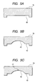
- Fig. 5 is a sectional view illustrating the forming process of the upper mold 4a.
- a circumferential edge molding portion 42 corresponding to the plate-like edge portion 3 which is formed at the circumferential edge of the lens portion 2 is formed (Fig. 5A).
- a lens surface molding portion 40 is formed, which corresponds to the lens portion 20 and is formed with a concave surface (Fig. 5B).
- a small hole 41 is formed, having the depth which is approximately less than four times the used wavelength of the lens portion 2 (Fig. 5C). After the lens surface molding portion 40 is formed, the formation of the small hole 41 is continuously performed. Therefore, in a state where the center of the lens surface molding portion 40 formed on the upper mold 4a is precisely aligned with the cutting tool 52, the small hole 41 can be formed. As described above, the upper mold 4a is formed.
- the upper and lower molds 4 are formed.
- the optical lens 1 is formed, which has the convex portion 23 of a small projection formed on each of the top portions 21 of both lens surfaces 20 constituted by a convex surface.
- each of the convex portions 23 is formed to correspond to the small hole 41 which are precisely formed in the center of the lens surface molding portion 40, the respective convex portions 23 are precisely formed in the top portions 21 of both lens surfaces 20.
- Figs. 6 and 7 are a sectional view and a plan view illustrating the eccentricity between both lens surfaces 20, respectively.
- both lens surfaces 20 are subject to be eccentric due to an arrangement error or the like when the upper and lower molds 4 are arranged to be opposed to each other.
- the respective convex portions 23 are arranged on the optical axis of both lens surfaces 20. Therefore, by measuring the positional deviation between the respective convex portions 23 with respect to the direction of the optical axis and adjusting the relative position between the upper and lower molds in the horizontal direction based on the measurement result, the optical lens 1 having no eccentricity can be formed.
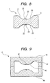
- an optical lens 1 in the present embodiment includes a lens portion 2 having a concave lens surface 20 on each side and a plate-like edge portion 3 which is formed at the circumferential edge of the lens portion 2.
- the lens portion 2 which is a single lens having the concave lens surface 20 on each side, refracts and transmits light.
- the edge portion 3 is formed at the circumferential edge of the lens portion 2 to be incorporated with the lens portion 2. Further, the edge portion 3 is mounted on a lens holder of an optical apparatus or the like to fix the lens portion 2 at a predetermined position.
- Both lens surfaces 20 and 20 of the lens portion 2 have a rotation-symmetry shape centered on a bottom portion 22, on which the convex portion 23 of a small projection is provided. That is, the convex portion 23 is formed on the optical axis of the lens surface 20.
- each of the convex portions 23 has the height, which is approximately less than four times the used wavelength, so as not to have an effect on an optical characteristic of the lens portion 2.
- the respective convex portions 23 shown in Fig. 8 are sufficiently small with respect to the lens surface 20, but they are enlarged in the drawings for convenience of the description in the present embodiment.
- each of the convex portions 23 is arranged in the rotation center of the lens surface 20, the positional deviation between the respective convex portions 23 with respect to the direction of the central axis is the deviation between both the optical axes of lens surfaces 20, that is, the eccentricity. Therefore, the same effect as the first embodiment can be obtained.
- the optical lens lin the present embodiment is formed by injection molding with the upper and lower molds 4 formed to correspond to the contour thereof.
- the upper and lower molds 4 are formed by cutting work, similarly to the first embodiment.
- FIG. 10 is a sectional view illustrating the forming process of the upper mold 4a.
- the lens surface molding portion 40 constituted by a convex surface corresponding to the lens surface 20 is formed on the surface 45 to be cut (Fig. 10A).
- a small hole 41 is formed, having the depth which is approximately less than four times the used wavelength of the lens portion 2 (Fig. 10B).
- the formation of the small hole 41 is continuously performed.
- the small hole 41 can be formed.
- a circumferential edge molding portion 42 corresponding to the plate-like edge portion 3 which is formed at the circumferential edge of the lens portion 2 is formed (Fig. 10C). As described above, the upper mold 4a is formed.
- the upper and lower molds 4 are formed.
- the optical lens 1 is formed, which has the convex portion 23 of a small projection on each of the bottom portions 22 of both lens surfaces 20 which are constituted by a concave surface.
- each of the convex portions 23 is formed to correspond to the small hole 41 which are precisely formed in the center of the lens surface molding portion 40, the convex portions 23 are precisely formed on the bottom portions 22 of both lens surfaces 20.
- the respective convex portions 23 are arranged on the optical axis of both lens surfaces 20. Therefore, even when both lens surfaces 20 are eccentric with each other, the relative position between the upper and lower molds 4 is adjusted in the horizontal direction based on the positional deviation between the respective convex portions 23 with respect to the direction of the optical axis, so that the optical lens 1 having no eccentricity can be formed.
- the optical lens 1 in the present embodiment includes the lens portion 2, of which one side is a convex surface and of which the other side is a concave surface, and the plate-like edge portion 3 which is formed at the circumferential edge of the lens portion 2.
- Both lens portions 20 and 20 of the lens portion 2 have a rotation-symmetry shape centered on the top portion 21 and the bottom portion 22, respectively.
- the convex portion 23 of a small projection is provided on the top portion 21 and the bottom portion 22, respectively.
- the convex portion 23 is formed on the optical axis of both the lens surfaces 20.
- each of the convex portions 23 has the height, which is approximately less than four times the used wavelength, so as not to have an effect on an optical characteristic of the lens portion 2.
- the respective convex portions 23 shown in Fig. 11 are sufficiently small with respect to the lens surface 20, but they are enlarged in the drawings for convenience of the description.
- each of the convex portions 23 is arranged in the rotation center of the lens surface 20, the positional deviation between the respective convex portions 23 with respect to the central axis is the deviation between optical axes of both the lens surfaces 20, that is, the eccentricity. Therefore, the same effect as the first embodiment or the second embodiment can be obtained.
- the optical lens 1 in the present embodiment is formed by injection molding with upper and lower molds 4 formed to correspond to the contour thereof.
- the upper and lower molds 4 are formed by cutting work, similarly to the first embodiment or the second embodiment. Then, the upper mold 4a by which the lens surface 20 is formed to be convex is formed in the same procedure as that of the first embodiment, and the lower mold 4a by which the lens surface 20 is formed to be concave is formed in the same procedure as that of the second embodiment.
- one side is formed to be a convex surface, and the other side is formed to be a concave surface.
- the optical lens 1 having the convex portions 23 on the optical axis of both lens surfaces 20 is formed.
- the respective convex portions 23 are arranged on the optical axis of both lens surfaces 20. Therefore, even when both lens surfaces 20 are eccentric with each other, the relative position between the upper and lower molds 4 is adjusted in the horizontal direction based on the positional deviation between the respective convex portions 23 with respect to the direction of the optical axis, so that the optical lens 1 having no eccentricity can be formed.
- the lens surface 20 is formed in a rotation-symmetry shape centered on the top portion 21 and bottom portion 22.
- the lens surface 20 is formed in an elliptic shape or an asymmetric shape, and if the convex portions 23 are formed on the optical axis of the lens surface 20, the amount of eccentricity can be easily calculated from the positional deviation between the respective convex portions 23.
- the optical lens 1 in the present embodiment includes the convex portion 23 having a cross shape, of which the intersection 24 is arranged on the top portion 21 of the lens surface 20.
- the intersection 24 is arranged on the bottom portion 22 of the lens surface 20.
- the intersection 24 is arranged on the optical axis of the lens surface.
- the respective convex portions 23 shown in Fig. 13 are sufficiently small with respect to the lens surface 20 so as not to have an effect on an optical characteristic of the lens portion 2, but they are enlarged in the drawings for convenience of the description.
- Each of the convex portions 23 is formed to correspond to the small hole 41 formed in the center of the lens surface molding portion 40 of the mold 4. Accordingly, two grooves for the small hole may be formed with the intersection being the center of the lens surface molding portion 40 and manufacture by cutting work is easily performed.
- the cross-shaped intersection 24 is arranged on the optical axis of the lens surface 20. Therefore, when the positional deviation between the respective convex portions 23 is measured by use of a microscope, it is easy to specify the positions of both lens surfaces 20 on the optical axis.
- the optical lens 1 in the present embodiment is provided with a plurality of circumferential-edge convex portions 31 which are formed at the corresponding positions of both surfaces of the edge portion 3 formed at the circumferential edge of the lens portion 2. Therefore, from the positional deviation between the plurality of circumferential-edge convex portions 31 and 31 corresponding to each other, the positional deviations between the respective convex portions 23 can be calculated. Based on the positional deviation between the respective convex portions 23, the relative position between the upper and lower molds 4 is adjusted, so that the optical lens 1 having no eccentricity is formed.
- the surface of the edge portion 3 having the circumferential-edge convex portions 31 is not an optically effective surface, an optical characteristic of the lens portion 2 does not need to be considered when the circumferential-edge convex portions 31 are formed.
- the optical lens 1 in the present embodiment includes the lens portion 2 having the convex lens surfaces 20 on each side and the plate-like edge portion 3 which is formed at the circumferential edge of the lens portion 2.
- Fig. 15 is a perspective view of the optical lens 1 in the present embodiment
- Fig. 16 is a vertical sectional view of Fig. 15.
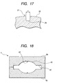
- Fig. 17 is an enlarged sectional view illustrating the concave portion 25.
- the concave portion 25 formed on the top portion 21 of the lens surface 20 is formed in a substantially cylindrical shape.
- the diameter of the base which is the opening surface on the lens surface 20 is in the range of 0.5 to 5 ⁇ m (0. 5 ⁇ m ⁇ d ⁇ 5 m).
- the positional deviation between the concave portions 25 with respect to the direction of the central axis are the deviation between optical axes of both the lens surfaces 20, that is, the eccentricity.
- the positional deviation between the respective concave portions 25 are obtained by the two-dimensional measurement with respect to the direction of the central axis by a microscope. Specifically, the focus of the microscope is first aligned with the one-side base of the concave portions 25 to be set to the center of the reference coordinate. Then, in a state where the coordinate is aligned, the focus of the microscope is moved to the other-side base of the concave portions 25 and the difference from the center coordinate is measured. That is, the measurement can be easily performed and the manufacturing cost can be reduced, compared to the conventional example.
- a permissible value of the eccentricity must be less than several micrometers, and measurement precision of the eccentricity amount is required to be less than 1 ⁇ m.
- the diameter d of the base of each of the concave portions 25 is less than 5 ⁇ m, an eccentricity amount can be calculated with high precision in the order of 1 ⁇ m.
- the diameter of the concave portion 25 is set to be larger than 0.5 ⁇ m, the concave portion 25 can be properly detected by a general microscope.
- an amount of eccentricity between both lens surfaces 20 is calculated by using the bases of the respective concave portions 25 as a reference. Therefore, if the diameter of the base of the concave portion 25 is in the range of 0.5 to 5 ⁇ m, the shape of the concave portion 25 is not limited to a cylindrical shape. For example, even though the shape is substantially conical, the eccentricity measurement can be performed with ease and with high precision.
- the diameter of the base of the concave portion 25 is set to be in the range of 1 to 2 ⁇ m, the depth thereof is set to about 0.5 ⁇ m, and magnifications of the microscope are set to 500, an eccentricity amount is measured, which proves that the eccentricity measurement can be performed with repeated-measurement precision of 0.2 ⁇ m and minute eccentricity more or less than 2 ⁇ m can be calculated extremely correctly.
- the optical lens 1 in the present embodiment is formed by injection molding by use of the upper and lower molds 4 formed to correspond to the contour thereof.
- the upper and lower molds 4 are formed by cutting work, similarly to the first embodiment.
- Fig. 19 is a sectional view illustrating the forming process of the upper mold 4a.
- the circumferential-edge molding portion 42 corresponding to the plate-like edge portion 3 which is formed at the circumferential edge of the lens portion 2 is formed on the surface 45 to be cut (Fig. 19A).
- the concave lens surface molding portion 40 corresponding to the lens surface 20 is formed (Fig. 19B).
- the lens surface molding portion 40 is formed so that a small projection 43 whose diameter is in the range of 0.5 to 5 ⁇ m is provided on the concave surface. That is, when the concave surface corresponding to the lens surface 20 is formed by cutting work, the lens surface molding portion 40 is formed so that the portion corresponding to the concave portion 25 is left. Therefore, in a state where the center of the lens surface molding portion 40 is precisely aligned with the cutting tool 52, the small projection 43 can be formed. As described above, the upper mold 4a is formed.
- the upper and lower molds 4 are formed.
- the optical lens 1 is formed, which has the concave portion 25 of a small hole on each of the top portions 21 of both lens surfaces 20 constituted by a convex surface.
- the concave portion 25 is precisely formed on each of the top portions 21 of both lens surfaces 20.
- the respective concave portions 25 are precisely arranged in the rotation center which is the optical axis of both lens surfaces 20, and the diameter of the base in the lens surface 20 is formed to be in the range of 0.5 to 5 ⁇ m. Therefore, the eccentricity between both lens surfaces 20 can be measured with ease and with high precision by a microscope. Further, as the relative position between the upper and lower molds 4 is adjusted in the horizontal direction based on the measurement result, the optical lens 1 which satisfies a permissible value of the eccentricity can be formed.
- the optical lens 1 in the present embodiment includes the lens portion 2 having the concave lens surfaces 20 on each side and the plate-like edge portion 3 which is formed at the circumferential edge of the lens portion 2. Further, the concave portion 25 is formed in each of the bottom portions 22 which is on the optical axis of the lens surface 20.
- the concave portion 25 which is formed on each lens surface 20 is the same as the concave portion 25 in the sixth embodiment, and the diameter of the base which is the opening surface on the lens surface 20 is in the range of 0.5 to 5 ⁇ m. That is, the positional deviation between the respective concave portions 25 arranged on the optical axis of the lens surface 20 is the eccentricity between both lens surfaces 20, and the same effect as the sixth embodiment can be obtained.
- the optical lens 1 in the present embodiment is formed by injection molding by use of the upper and lower molds 4 formed to correspond to the contour thereof.
- the upper and lower molds 4 are formed by cutting work, similarly to the sixth embodiment.
- FIG. 22 is a sectional view illustrating the forming process of the upper mold 4a.
- the convex lens surface molding portion 40 corresponding to the lens surface 20 is formed (Fig. 22A).
- the les surface molding portion 40 is formed so that the small projection 43 whose diameter is in the range of 0.5 to 5 ⁇ m is provided in the convex surface.
- the lens surface molding portion 40 is formed so that the portion corresponding to the concave portion 25 is left. Therefore, in a state where the center of the lens surface molding portion 40 is precisely aligned with the cutting tool 52, the small projection 43 can be formed.
- the circumferential-edge molding portion 42 corresponding to the plate-like edge portion 3 which is formed at the circumferential edge of the lens portion 2 is formed (Fig. 22B). As described above, the upper mold 4a is formed.
- the upper and lower molds 4 are formed.
- the optical lens 1 is formed, which includes the concave portion 25 of a small hole on each of the bottom portions 22 of both lens surfaces 20 which are constituted by a concave surface.
- each of the concave portions 25 is formed to correspond to the small projection 43 which is precisely formed in the center of the lens surface molding portion 40, the concave portion 25 is precisely formed in each of the bottom portions 22 of both lens surfaces 20.
- the respective concave portions 25 are precisely arranged on the rotation center which is the optical axis of both lens surfaces 20, and the diameter of the base in the lens surface 20 is in the range of 0.5 to 5 ⁇ m. Therefore, the eccentricity between both lens surfaces 20 can be measured with ease and with high precision by a microscope. Further, as the relative position between the upper and lower molds 4 is adjusted in the horizontal direction based on the measurement result, the optical lens 1 which satisfies a permissible value of the eccentricity can be formed.
- the optical lens 1 in the present embodiment includes the lens portion 2 of which one side is a convex surface and of which the other side is a concave surface and the plate-like edge portion 3 which is formed at the circumferential edge of the lens portion 2. Further, both lens surfaces 20 of the lens portion 2 are formed to have a rotation-symmetry shape centered on the top portion 21 and the bottom portion 22, respectively. On each of the top portion 21 and the bottom portion 22, the concave portion 25 of a small hole is provided.
- the concave portion 25 formed on each lens surface 20 is the same as the concave portion 25 in the seventh embodiment or the seventh embodiment, and the diameter of the base which is the opening surface on the lens surface 20 is in the range of 0.5 to 5 ⁇ m. That is, the positional deviation between the respective concave portions 25 arranged on the optical axis of the lens surface 20 is the eccentricity between both lens surfaces 20, and the same effect as the sixth embodiment or the seventh embodiment can be obtained.
- the optical lens 1 in the present embodiment is formed by injection molding by use of the upper and lower molds 4 formed to corresponding to the contour thereof.
- the upper and lower molds 4 are formed by cutting work, similarly to the sixth embodiment or the seventh embodiment.
- the upper mold 4a by which the lens surface 20 is formed to be convex is formed in the same procedure as that of the sixth embodiment and the lower mold 4b by which the lens surface 20 is formed to be concave is formed in the same procedure as that of the seventh embodiment.
- the optical lens 1 is formed, of which one side is a convex surface, of which the other side is a concave surface, and which has the concave portion 24 on the optical axis of both lens surfaces 20.
- the respective concave portions 25 are arranged on the optical axis of both lens surfaces 20, and the diameter of the base in the lens surface 20 is in the range of 0.5 to 5 ⁇ m. Therefore, the eccentricity between both lens surfaces 20 can be measured with ease and with high precision by a microscope. Further, as the relative position between the upper and lower molds 4 is adjusted in the horizontal direction based on the measurement result, the optical lens 1 which satisfies a permissible value of the eccentricity can be formed.
- the lens surface 20 is formed to have a rotation-symmetry shape centered on the top portion 21 or the bottom portion 22.
- the lens surface 20 is formed to have an elliptical shape or asymmetric shape, and if the concave portion 25 is formed on the optical axis of each lens surface 20, the eccentricity amount can be easily calculated from the positional deviation between the respective concave portions 25, similarly to the respective above-described embodiments.
- the optical lens 1 in the present embodiment includes the concave portion 25 in each of the top portions 21 of both lens surfaces 20, and the shape in the vicinity of the concave portion 25 is different from that of the sixth embodiment.
- Fig. 25 is an enlarged sectional view in the vicinity of the concave portion 25 of the optical lens 1 in the present embodiment
- Fig. 26 is an enlarged plan view in the vicinity of the concave portion 25.
- the optical lens 1 in the present embodiment includes a concentrically stepped portion 26 centered on the top portion 21 of the lens surface 20 on which the concave portion 25 is formed.
- the stepped portion 26 is formed in the range where it can be observed simultaneously with the concave portion 25 when the lens surface 20 is seen through a microscope for measurement of eccentricity.
- the concave portion 25, which is the base point of the eccentricity measurement of both lens surfaces 20 of the formed optical lens 1, has the detectable size when it is seen through a microscope.
- the concave portion 25 is formed in the center of the stepped portion 26, the concave portion can easily be detected without being confused with a scratch or the like.
- the stepped portion 26 when measured by using a differential interference microscope, the stepped portion 26 is formed in a ring shape centered on the top portion 21. Therefore, even though the difference in size between the stepped portions is set to about 10 ⁇ m, the stepped portion 26 can be clearly identified. Further, the stepped portion 26 is a concentric step centered on the top portion 21 of the lens surface 20, and the mold 4 can be formed by rotation cutting work. Therefore, the stepped portion 26 is easily manufactured by cutting work.
- the orientation concave portion 27 is formed only in the direction of a gate into which molten resin is injected, so that the flow direction of the molten resin from the concave portion 25 formed in the rotation center of the lens surface 20 can be known. Accordingly, the eccentricity amount with respect to the flow direction of molten resin and the orthogonal direction thereto can be measured, which is useful in evaluating the eccentricity between the lens surfaces 20.
- the orientation concave portion 27 is provided on the step of the stepped portion 26, the orientation concave portion 27 and the concave portion 25 can be easily distinguished.
- the embodiments of the present invention have been described, but the application of the present invention is not limited to these embodiments. Various applications can be made within the scope without departing from the spirit of the present invention.
- the shape of the convex portion 23 or the concave portion 25 is the shape which can easily specify the position on the optical axis of the lens surface 20, any shape may be used, without being limited to the present embodiment.
- each lens surface of the lens portion has the convex portion of a small projection centered on the optical axis thereof, and so the amount of eccentricity between both lens surfaces is obtained from the positional deviation between the respective convex portions.
- the amount of eccentricity can be easily obtained, and a manufacturing cost can be reduced.
- each lens surface of the lens portion has the concave portion of a small hole centered on the optical axis thereof, and the concave portion, of which the base has a diameter in the range of 0.5 to 5 ⁇ m, has a substantially cylindrical shape or a substantially conical shape. Therefore, an eccentricity amount can be calculated with ease and with high precision from the positional deviation between the respective concave portions, and productivity and product precision can be enhanced.
- the convex portion is formed in a cross shape, and the intersection of the cross shape is arranged on the optical axis of the lens surface. Therefore, two grooves may be formed on the mold so as to correspond to the convex portion, and manufacture thereof is easily performed by cutting work.
- each lens surface of the lens portion has the concentric stepped portion centered on the concave portion in the vicinity of the concave portion or centered on the convex portion in the vicinity of the convex portion. Therefore, even when a minute foreign matter or a minute scratch exists in the vicinity of the concave portion or the convex portion, an eccentricity can be correctly measured without being confused.
- each lens surface of the lens portion has an orientation concave portion or an orientation convex portion at the position corresponding thereto in the vicinity of the concave portion or the convex portion. Therefore, the position of a gate can be confirmed by the orientation concave portion or the orientation convex portion, and the amount of eccentricity with respect to the flow direction of molten resin and the direction orthogonal thereto can be easily measured.
- the plate-like edge portion is formed at the circumferential edge of the lens portion
- the plurality of circumferential-edge convex portions are formed at the corresponding positions on both surfaces of the edge portion
- the positional deviation between the respective convex portions is calculated from the positional deviation between the plurality of circumferential-edge convex portions corresponding to each other. Therefore, the positional deviation between the respective convex portions can be measured with high precision.
- the small hole for the convex portion is formed to have the depth which is approximately less than four times the used length, centered on the position corresponding to the optical axis of the lens surface. Then, the lens portion is formed by injection molding by use of the upper and lower molds on which the lens surface molding portion is formed. Based on the positional deviation between the respective convex portions provided on the optical axis of both lens surfaces, the relative position between the upper and lower molds is adjusted. Therefore, the optical lens having no eccentricity can be formed.
- the lens surface molding portion which is constituted by a convex surface or a concave surface corresponding to the lens surface is formed in each of the upper and lower molds.
- the lens surface molding portion has the small hole for the concave portion having a substantially cylindrical shape or a substantially conical shape, of which the base has a diameter in the range of 0.5 to 5 ⁇ m, the small hole being centered on the position corresponding to the optical axis of the lens surface.
- the lens portion is formed by injection molding by use of the upper and lower molds on which the lens surface molding portion is formed. Based on the positional deviation between the respective convex portions provided on the optical axis of both lens surfaces, the relative position between the upper and lower molds is adjusted. Therefore, the optical lens having no eccentricity can be formed.
Landscapes
- Physics & Mathematics (AREA)
- Engineering & Computer Science (AREA)
- General Physics & Mathematics (AREA)
- Optics & Photonics (AREA)
- Health & Medical Sciences (AREA)
- Manufacturing & Machinery (AREA)
- Ophthalmology & Optometry (AREA)
- Mechanical Engineering (AREA)
- Moulds For Moulding Plastics Or The Like (AREA)
Abstract
In an optical lens including a lens portion having a convex or concave lens surface on each side, each lens surface of the lens portion has a convex portion of a small projection centered on the optical axis thereof, and the convex portion has the height which is approximately less than four times the used wavelength so as not to have an effect on an optical characteristic of the lens portion.
Description
- The present invention relates to an optical lens having a lens surface on each surface and a method of manufacturing the same, and more specifically, to an optical lens that is injection-molded by a mold and that has a convex portion or a concave portion in the center of both lens surfaces and a method of manufacturing the same.
- As a method of manufacturing an optical lens such as a photographing lens of a camera or an imaging lens of an optical element, an injection-molding method is generally used, which is suitable for mass production at a low cost. In the injection-molding method, upper and lower molds which are formed to correspond to the contour of a desired molded product are arranged to be opposed to each other, a molten material is injected into the space between the upper and lower molds to be cooled and solidified, and then a molding product is formed.
- In addition, in order to image an object by use of the formed optical lens, a plurality of optical lens are generally arranged in the direction of the optical axis to constitute a lens system. Since the deviation between the central axes of the respective lenses becomes a cause of reduction in resolution, it is necessary that the respective lenses constituting the lens system should be arranged with high precision. The deviation between the central axes of the lenses can be adjusted by a piezoelectric element which is arranged in each of the lenses to be moved minutely. As such an adjusting method, for example, there is provided a method exemplified in Japanese Unexamined Patent Application Publication No. 2002-277705.
- However, in the above-described adjusting method in which an optical lens having a lens shape on each side is used, there is no countermeasure against the case where both lens surfaces are deviated with respect to the central axis to be eccentric with each other due to an arrangement error of the upper and lower molds when the optical lens is molded. In the case of the eccentricity of a single lens, the eccentricity amount of both lens surfaces is measured, and based on the measurement result, the positions of the molds are adjusted. However, in the conventional method of measuring the eccentricity of a single lens, the center of the lens surface is calculated from the contour of the lens and the height of the lens, respectively, and then, the deviation between the centers of both surfaces is measured, which means that the measurement becomes complicated because a three-dimensional measuring machine needs to be used.
- In addition, as digital cameras are recently miniaturized and have high resolution, lenses are also required to be miniaturized and have high resolution. Further, a permissible value of an eccentricity amount of a single lens is less than several micrometers. The difference between the virtual center calculated by the above-described method and the actual optical center easily occurs. In particular, in the case of an injection-molded optical lens, the contour of the lens is easily distorted due to the flow of injected resin, so that an eccentricity amount_is hardly measured and adjusted with high precision.
- The present invention has been made in view of the above problems. It is therefore an object of the present invention to provide an optical lens which is molded by a mold and by which an amount of eccentricity between both lens surfaces can be measured and adjusted precisely with a simple method and a method of manufacturing the optical lens.
- According to an aspect of the present invention, an optical lens includes a lens portion having a convex or concave lens surface on each side. Each lens surface of the lens portion has a convex portion constituted by a small projection centered on the optical axis thereof, and the convex portion has the height which is approximately less than four times the used wavelength so as not to have an effect on an optical characteristic of the lens portion.
- According to another aspect of the present invention, an optical lens includes a lens portion having a convex or concave lens surface on each side. Each lens surface of the lens portion has a concave portion of a small hole centered on the optical axis thereof, the concave portion is formed in a substantially cylindrical shape or a substantially conical shape, and the diameter of the base is in the range of 0.5 to 5 µm.
- According to still another aspect of the optical lens according to the invention, the convex portion is formed in a cross shape and the intersection of the cross shape is arranged on the optical axis of the lens surface.
- According to still another aspect of the optical lens_according to the invention, each lens surface of the lens portion has a concentric stepped portion centered on the concave portion or the convex portion in the vicinity of the concave portion or the convex portion.
- According to still another aspect of the optical lens according to the invention, each lens surface of the lens portion has an orientation concave portion or an orientation convex portion at the position where both lens surfaces are opposed to each other in the vicinity of the concave portion or the convex portion.
- According to still another aspect of the optical lens according to the invention, a plate-like edge portion is formed on the circumferential edge of the lens portion and, on both surfaces of the edge portion, a plurality of circumferential-edge convex portions are formed at the position corresponding thereto.
- According to still another aspect of the invention, a method of manufacturing an optical lens, which is formed by upper and lower molds and includes a lens portion having a convex lens surface or a concave lens surface on each side, includes forming a lens surface molding portion which is constituted by a convex surface or a concave surface corresponding to the lens surface in each of the upper and lower molds and simultaneously, forming a small hole, which has the depth which is less than four times the used wavelength of the lens portion, the small hole being centered on the position corresponding to the optical axis of the lens surface; injection-molding the lens portion by use of the upper and lower molds on which the lens surface molding portion is formed; and based on the positional deviation between the respective convex portions formed on each lens surface by the small hole, adjusting the relative position between the upper and lower molds.
- According to still another aspect of the invention, a method of manufacturing an optical lens, which is formed by upper and lower molds and includes a lens portion having a convex lens surface or a concave lens surface on each side, includes forming a lens surface molding portion which is constituted by a convex surface or a concave surface corresponding to the lens surface in each of the upper and lower molds and which has a small projection having a substantially cylindrical shape or substantially conical shape of which the base has the diameter in a range of 0.5 to 5 µm, the small projection being centered on the position corresponding to the optical axis of the lens surface; injection-molding the lens portion by use of the upper and lower molds on which the lens surface molding portion is formed; and based on the positional deviation between the respective concave portions formed on each lens surface by the small projection, adjusting the relative position between the upper and lower molds.
-
- Fig. 1 is a perspective view illustrating an optical lens in the present embodiment;
- Fig. 2 is a vertical sectional view of Fig. 1;
- Fig. 3 is a vertical sectional view illustrating upper and lower molds for forming the optical lens in the present embodiment;
- Fig. 4 is a schematic view illustrating a mold forming apparatus;
- Fig. 5 is a vertical sectional view illustrating the forming processes (A to C) of the upper and lower molds in the present embodiment;
- Fig. 6 is an enlarged sectional view illustrating the eccentricity of the lens surface;
- Fig. 7 is an enlarged plan view illustrating the eccentricity of the lens surface;
- Fig. 8 is a vertical sectional view illustrating an optical lens in the second embodiment;
- Fig. 9 is a vertical sectional view illustrating upper and lower molds for forming the optical lens in the second embodiment;
- Fig. 10 is a vertical sectional view illustrating the forming processes (A to C) of the upper and lower molds in the second embodiment;
- Fig. 11 is a vertical sectional view illustrating an optical lens in the third embodiment;
- Fig. 12 is a vertical sectional view illustrating upper and lower molds for forming the optical lens in the third embodiment;
- Fig. 13 is a perspective view illustrating an optical lens in the fourth embodiment;
- Fig. 14 is a perspective view illustrating an optical lens in the fifth embodiment;
- Fig. 15 is a perspective view illustrating an optical lens in the sixth embodiment;
- Fig. 16 is a vertical sectional view of Fig. 15;
- Fig. 17 is an enlarged sectional view of a concave portion;
- Fig. 18 is a vertical sectional view illustrating upper and lower molds for forming the optical lens in the sixth embodiment;
- Fig. 19 is a vertical sectional view illustrating the forming processes (A to B) of the upper and lower molds in the sixth embodiment;
- Fig. 20 is a vertical sectional view illustrating an optical lens in the seventh embodiment;
- Fig. 21 is a vertical sectional view illustrating upper and lower molds for forming the optical lens in the seventh embodiment;
- Fig. 22 is a vertical sectional view illustrating the forming processes (A to B) of the upper and lower molds in the seventh embodiment;
- Fig. 23 is a vertical sectional view illustrating an optical lens in the eighth embodiment;
- Fig. 24 is a vertical sectional view illustrating upper and lower molds for forming the optical lens in the eighth embodiment;
- Fig. 25 is an enlarged sectional view in the vicinity of a concave portion in the ninth embodiment;
- Fig. 26 is an enlarged plan view in the vicinity of the concave portion; and
- Fig. 27 is a diagram illustrating another embodiment in Fig. 25.
- Preferred embodiments of the present invention will now be described in detail with reference to the drawings. Fig. 1 is a perspective view of an
optical lens 1 in the present embodiment, and Fig.'2 is a vertical sectional view of Fig. 1. As shown in Figs. 1 and 2, theoptical lens 1 in the present embodiment, which is used in an optical apparatus such as a camera, includes alens portion 2 having aconvex lens surface 20 on each side and a plate-like edge portion 3 which is formed at the circumferential edge of thelens portion 2. - The
lens portion 2, having theconvex lens surfaces 20 on each side, refracts and transmits light. In addition, theedge portion 3 is formed at the circumferential edge of thelens portion 2 to be incorporated with thelens portion 2. Theedge portion 3 is mounted on a lens holder of an optical apparatus or the like to fix the lens portion at a predetermined position. - Both of the lens surfaces 20 of the
lens portion 2 have a rotation-symmetry shape centered on atop portion 21. Thelens portion 2 has aconvex portion 23 of a small projection on each of thetop portions 21 of the lens surfaces 20. That is, theconvex portion 23 is formed on the optical axis of thelens surface 20. Here, the respectiveconvex portions 23 have the height which is approximately less than four times a used wavelength so as not to have an effect on an optical characteristic of thelens portion 2. If the height is less than 5 µm, theconvex portion 23 hardly has an effect on an optical characteristic of thelens portion 2. The wavelength of visible light is in the range of 0.4 to 0.7 µm. When the used wavelength is set to 0.55 µm which is the intermediate value of the above range, and even though the used wavelength is quadrupled, the value is about 2 µm. Therefore, the formedconvex portion 23 does not have an effect on an optical characteristic of thelens portion 2. Moreover, as a practical matter, the respectiveconvex portions 23 shown in Figs. 1 and 2 are sufficiently small with respect to thelens surface 20 so as not to have an effect on an optical characteristic of thelens portion 2, but they are enlarged in the drawings for convenience of the description in the present embodiment. - Since each of the
convex portions 23 is disposed in the rotation center of thelens portion 20, the positional deviation between the respectiveconvex portions 23 with respect to the direction of the central axis is the deviation between the optical axes of both the lens surfaces 20, that is, the eccentricity. Here, the positional deviation between the respectiveconvex portions 23 is obtained by the two-dimensional measurement with respect to the direction of the central axis by a microscope. Since the amount of eccentricity between the lens surfaces 20 can be obtained by measuring the positional deviation between the respectiveconvex portions 23, the amount of eccentricity can be easily measured and the manufacturing cost can be reduced, compared to the conventional example. - The
optical lens 1 in the present embodiment is formed by the following method. As shown in Fig. 3, upper andlower molds 4, which are formed so as to correspond to the contour of theoptical lens 1, are arranged to be opposed to each other, and then a molten material is injected into the space between the upper and lower molds to be cooled and solidified, which is referred to as the injection molding method. Here, the upper andlower molds 4 are generally made of a steel material, because they need to be rigid enough not to be deformed by a pressing force when a material is injected into the space. In addition, there is a case where a copper alloy or an aluminum alloy is used for increasing cooling efficiency. - The upper and
lower molds 4 are formed by cutting work. Fig. 4 is a schematic diagram illustrating a mold forming apparatus. In order to form eachmold 4, first, themold 4 is held so that asurface 45 to be cut is orthogonal to arotation shaft 51 of alathe 5. Then, themold 4 is rotated by the rotation of therotation shaft 51 of thelathe 5. Further, a bite which is acutting tool 52 is arranged in the direction perpendicular to thesurface 45 to be cut and cuts in thesurface 45 to be cut while moving. Then, themold 4 is formed in a predetermined shape. - Here, a method of manufacturing the
optical lens 1 in the present embodiment will be concretely described. To begin with, among the upper andlower molds 4 for forming theoptical lens 1 in the present embodiment, a method of forming theupper mold 4a will be described. Fig. 5 is a sectional view illustrating the forming process of theupper mold 4a. First, on thesurface 45 to be cut, a circumferentialedge molding portion 42 corresponding to the plate-like edge portion 3 which is formed at the circumferential edge of thelens portion 2 is formed (Fig. 5A). Next, a lenssurface molding portion 40 is formed, which corresponds to thelens portion 20 and is formed with a concave surface (Fig. 5B). Then, in the center of the lenssurface molding portion 40 corresponding to the rotation center of thelens surface 20, asmall hole 41 is formed, having the depth which is approximately less than four times the used wavelength of the lens portion 2 (Fig. 5C). After the lenssurface molding portion 40 is formed, the formation of thesmall hole 41 is continuously performed. Therefore, in a state where the center of the lenssurface molding portion 40 formed on theupper mold 4a is precisely aligned with the cuttingtool 52, thesmall hole 41 can be formed. As described above, theupper mold 4a is formed. - Similarly, by performing the same operation as the above-described operation for the
lower mold 4a, the upper andlower molds 4 are formed. By injection molding by use of the formed upper andlower molds 4, theoptical lens 1 is formed, which has theconvex portion 23 of a small projection formed on each of thetop portions 21 of both lens surfaces 20 constituted by a convex surface. Here, since each of theconvex portions 23 is formed to correspond to thesmall hole 41 which are precisely formed in the center of the lenssurface molding portion 40, the respectiveconvex portions 23 are precisely formed in thetop portions 21 of both lens surfaces 20. - Figs. 6 and 7 are a sectional view and a plan view illustrating the eccentricity between both lens surfaces 20, respectively. As shown in Figs. 6 and 7, even though forming precision of the
mold 4 is sufficiently ensured, both lens surfaces 20 are subject to be eccentric due to an arrangement error or the like when the upper andlower molds 4 are arranged to be opposed to each other. Here, the respectiveconvex portions 23 are arranged on the optical axis of both lens surfaces 20. Therefore, by measuring the positional deviation between the respectiveconvex portions 23 with respect to the direction of the optical axis and adjusting the relative position between the upper and lower molds in the horizontal direction based on the measurement result, theoptical lens 1 having no eccentricity can be formed. - Next, the second embodiment will be described. As shown in Fig. 8, an
optical lens 1 in the present embodiment includes alens portion 2 having aconcave lens surface 20 on each side and a plate-like edge portion 3 which is formed at the circumferential edge of thelens portion 2. - The
lens portion 2, which is a single lens having theconcave lens surface 20 on each side, refracts and transmits light. In addition, theedge portion 3 is formed at the circumferential edge of thelens portion 2 to be incorporated with thelens portion 2. Further, theedge portion 3 is mounted on a lens holder of an optical apparatus or the like to fix thelens portion 2 at a predetermined position. - Both lens surfaces 20 and 20 of the
lens portion 2 have a rotation-symmetry shape centered on abottom portion 22, on which theconvex portion 23 of a small projection is provided. That is, theconvex portion 23 is formed on the optical axis of thelens surface 20. Here, each of theconvex portions 23 has the height, which is approximately less than four times the used wavelength, so as not to have an effect on an optical characteristic of thelens portion 2. Here, as a practical matter, the respectiveconvex portions 23 shown in Fig. 8 are sufficiently small with respect to thelens surface 20, but they are enlarged in the drawings for convenience of the description in the present embodiment. - Since each of the
convex portions 23 is arranged in the rotation center of thelens surface 20, the positional deviation between the respectiveconvex portions 23 with respect to the direction of the central axis is the deviation between both the optical axes of lens surfaces 20, that is, the eccentricity. Therefore, the same effect as the first embodiment can be obtained. - As shown in Fig. 9, the optical lens lin the present embodiment is formed by injection molding with the upper and
lower molds 4 formed to correspond to the contour thereof. In addition, the upper andlower molds 4 are formed by cutting work, similarly to the first embodiment. - A method of manufacturing the
optical lens 1 in the present embodiment will be concretely described. To being with, among the upper andlower molds 4, the formation of theupper mold 4a will be described. Fig. 10 is a sectional view illustrating the forming process of theupper mold 4a. First, the lenssurface molding portion 40 constituted by a convex surface corresponding to thelens surface 20 is formed on thesurface 45 to be cut (Fig. 10A). Then, in the center of the lenssurface molding portion 40 corresponding to the rotation center of thelens surface 20, asmall hole 41 is formed, having the depth which is approximately less than four times the used wavelength of the lens portion 2 (Fig. 10B). After the lenssurface molding portion 40 is formed, the formation of thesmall hole 41 is continuously performed. Therefore, in a state where the center of the lenssurface molding portion 40 formed on theupper mold 4a is precisely aligned with the cuttingtool 52, thesmall hole 41 can be formed. Next, a circumferentialedge molding portion 42 corresponding to the plate-like edge portion 3 which is formed at the circumferential edge of thelens portion 2 is formed (Fig. 10C). As described above, theupper mold 4a is formed. - Similarly, by performing the same operation as the above operation for the
lower mold 4b, the upper andlower molds 4 are formed. By injection molding with the formed upper andlower molds 4, theoptical lens 1 is formed, which has theconvex portion 23 of a small projection on each of thebottom portions 22 of both lens surfaces 20 which are constituted by a concave surface. Here, since each of theconvex portions 23 is formed to correspond to thesmall hole 41 which are precisely formed in the center of the lenssurface molding portion 40, theconvex portions 23 are precisely formed on thebottom portions 22 of both lens surfaces 20. - Here, similarly to the first embodiment, the respective
convex portions 23 are arranged on the optical axis of both lens surfaces 20. Therefore, even when both lens surfaces 20 are eccentric with each other, the relative position between the upper andlower molds 4 is adjusted in the horizontal direction based on the positional deviation between the respectiveconvex portions 23 with respect to the direction of the optical axis, so that theoptical lens 1 having no eccentricity can be formed. - Next, a third embodiment will be described. As shown in Fig. 11, the
optical lens 1 in the present embodiment includes thelens portion 2, of which one side is a convex surface and of which the other side is a concave surface, and the plate-like edge portion 3 which is formed at the circumferential edge of thelens portion 2. - Both
lens portions lens portion 2 have a rotation-symmetry shape centered on thetop portion 21 and thebottom portion 22, respectively. On thetop portion 21 and thebottom portion 22, theconvex portion 23 of a small projection is provided. That is, theconvex portion 23 is formed on the optical axis of both the lens surfaces 20. Here, similarly to the first or the second embodiment, each of theconvex portions 23 has the height, which is approximately less than four times the used wavelength, so as not to have an effect on an optical characteristic of thelens portion 2. Here, as a practical matter, the respectiveconvex portions 23 shown in Fig. 11 are sufficiently small with respect to thelens surface 20, but they are enlarged in the drawings for convenience of the description. - Since each of the
convex portions 23 is arranged in the rotation center of thelens surface 20, the positional deviation between the respectiveconvex portions 23 with respect to the central axis is the deviation between optical axes of both the lens surfaces 20, that is, the eccentricity. Therefore, the same effect as the first embodiment or the second embodiment can be obtained. - As shown in Fig. 12, the
optical lens 1 in the present embodiment is formed by injection molding with upper andlower molds 4 formed to correspond to the contour thereof. The upper andlower molds 4 are formed by cutting work, similarly to the first embodiment or the second embodiment. Then, theupper mold 4a by which thelens surface 20 is formed to be convex is formed in the same procedure as that of the first embodiment, and thelower mold 4a by which thelens surface 20 is formed to be concave is formed in the same procedure as that of the second embodiment. - By injection molding with the formed upper and
lower molds 4, one side is formed to be a convex surface, and the other side is formed to be a concave surface. In addition, theoptical lens 1 having theconvex portions 23 on the optical axis of both lens surfaces 20 is formed. Here, similarly to the first embodiment or the second embodiment, the respectiveconvex portions 23 are arranged on the optical axis of both lens surfaces 20. Therefore, even when both lens surfaces 20 are eccentric with each other, the relative position between the upper andlower molds 4 is adjusted in the horizontal direction based on the positional deviation between the respectiveconvex portions 23 with respect to the direction of the optical axis, so that theoptical lens 1 having no eccentricity can be formed. - In the first to the third embodiments, the
lens surface 20 is formed in a rotation-symmetry shape centered on thetop portion 21 andbottom portion 22. However, even when thelens surface 20 is formed in an elliptic shape or an asymmetric shape, and if theconvex portions 23 are formed on the optical axis of thelens surface 20, the amount of eccentricity can be easily calculated from the positional deviation between the respectiveconvex portions 23. - Next, the fourth embodiment will be described. As shown in Fig. 13, the
optical lens 1 in the present embodiment includes theconvex portion 23 having a cross shape, of which theintersection 24 is arranged on thetop portion 21 of thelens surface 20. Similarly, when the shape of thelens surface 20 is concave, theintersection 24 is arranged on thebottom portion 22 of thelens surface 20. When thelens surface 20 is not formed in a rotation-symmetry shape, theintersection 24 is arranged on the optical axis of the lens surface. Here, as a practical matter, the respectiveconvex portions 23 shown in Fig. 13 are sufficiently small with respect to thelens surface 20 so as not to have an effect on an optical characteristic of thelens portion 2, but they are enlarged in the drawings for convenience of the description. - Each of the
convex portions 23 is formed to correspond to thesmall hole 41 formed in the center of the lenssurface molding portion 40 of themold 4. Accordingly, two grooves for the small hole may be formed with the intersection being the center of the lenssurface molding portion 40 and manufacture by cutting work is easily performed. In addition, thecross-shaped intersection 24 is arranged on the optical axis of thelens surface 20. Therefore, when the positional deviation between the respectiveconvex portions 23 is measured by use of a microscope, it is easy to specify the positions of both lens surfaces 20 on the optical axis. - Next, the fifth embodiment will be described. As shown in Fig. 14, the
optical lens 1 in the present embodiment is provided with a plurality of circumferential-edgeconvex portions 31 which are formed at the corresponding positions of both surfaces of theedge portion 3 formed at the circumferential edge of thelens portion 2. Therefore, from the positional deviation between the plurality of circumferential-edgeconvex portions convex portions 23 can be calculated. Based on the positional deviation between the respectiveconvex portions 23, the relative position between the upper andlower molds 4 is adjusted, so that theoptical lens 1 having no eccentricity is formed. Here, since the surface of theedge portion 3 having the circumferential-edgeconvex portions 31 is not an optically effective surface, an optical characteristic of thelens portion 2 does not need to be considered when the circumferential-edgeconvex portions 31 are formed. - Next, the sixth embodiment will be described. Similarly to the first embodiment, the
optical lens 1 in the present embodiment includes thelens portion 2 having the convex lens surfaces 20 on each side and the plate-like edge portion 3 which is formed at the circumferential edge of thelens portion 2. Fig. 15 is a perspective view of theoptical lens 1 in the present embodiment, and Fig. 16 is a vertical sectional view of Fig. 15. - As shown in Figs. 15 and 16, on the
top portions 21 of both lens surfaces 20 of theoptical lens 1 in the present embodiment,concave portions 25 constituted by a small hole are provided, unlike the first embodiment. Fig. 17 is an enlarged sectional view illustrating theconcave portion 25. - As shown in Fig. 17, the
concave portion 25 formed on thetop portion 21 of thelens surface 20 is formed in a substantially cylindrical shape. The diameter of the base which is the opening surface on thelens surface 20 is in the range of 0.5 to 5 µm (0. 5 µm < d < 5 m). - Since the respective
concave portions 25 are arranged in the rotation center of thelens surface 20, the positional deviation between theconcave portions 25 with respect to the direction of the central axis are the deviation between optical axes of both the lens surfaces 20, that is, the eccentricity. The positional deviation between the respectiveconcave portions 25 are obtained by the two-dimensional measurement with respect to the direction of the central axis by a microscope. Specifically, the focus of the microscope is first aligned with the one-side base of theconcave portions 25 to be set to the center of the reference coordinate. Then, in a state where the coordinate is aligned, the focus of the microscope is moved to the other-side base of theconcave portions 25 and the difference from the center coordinate is measured. That is, the measurement can be easily performed and the manufacturing cost can be reduced, compared to the conventional example. - In addition, as digital cameras are recently miniaturized and have high resolution, lenses are also required to be miniaturized and have high resolution. Further, a permissible value of the eccentricity must be less than several micrometers, and measurement precision of the eccentricity amount is required to be less than 1 µm. In the present embodiment, since the diameter d of the base of each of the
concave portions 25 is less than 5 µm, an eccentricity amount can be calculated with high precision in the order of 1 µm. In addition, when the diameter of theconcave portion 25 is set to be larger than 0.5 µm, theconcave portion 25 can be properly detected by a general microscope. - An amount of eccentricity between both lens surfaces 20 is calculated by using the bases of the respective
concave portions 25 as a reference. Therefore, if the diameter of the base of theconcave portion 25 is in the range of 0.5 to 5 µm, the shape of theconcave portion 25 is not limited to a cylindrical shape. For example, even though the shape is substantially conical, the eccentricity measurement can be performed with ease and with high precision. - In the present embodiment, in a state where the diameter of the base of the
concave portion 25 is set to be in the range of 1 to 2 µm, the depth thereof is set to about 0.5 µm, and magnifications of the microscope are set to 500, an eccentricity amount is measured, which proves that the eccentricity measurement can be performed with repeated-measurement precision of 0.2 µm and minute eccentricity more or less than 2 µm can be calculated extremely correctly. - As shown in Fig. 18, the
optical lens 1 in the present embodiment is formed by injection molding by use of the upper andlower molds 4 formed to correspond to the contour thereof. In addition, the upper andlower molds 4 are formed by cutting work, similarly to the first embodiment. - Here, a method of manufacturing the
optical lens 1 in the present embodiment will be concretely described. To begin with, among the upper andlower molds 4 forming theoptical lens 1 in the present embodiment, the formation of theupper mold 4a will be described. Fig. 19 is a sectional view illustrating the forming process of theupper mold 4a. First, the circumferential-edge molding portion 42 corresponding to the plate-like edge portion 3 which is formed at the circumferential edge of thelens portion 2 is formed on thesurface 45 to be cut (Fig. 19A). Next, the concave lenssurface molding portion 40 corresponding to thelens surface 20 is formed (Fig. 19B). At this time, in the center of the concave surface corresponding to the rotation center of thelens surface 20, the lenssurface molding portion 40 is formed so that asmall projection 43 whose diameter is in the range of 0.5 to 5 µm is provided on the concave surface. That is, when the concave surface corresponding to thelens surface 20 is formed by cutting work, the lenssurface molding portion 40 is formed so that the portion corresponding to theconcave portion 25 is left. Therefore, in a state where the center of the lenssurface molding portion 40 is precisely aligned with the cuttingtool 52, thesmall projection 43 can be formed. As described above, theupper mold 4a is formed. - Similarly, by performing the same operation as the above-described operation for the
lower mold 4a, the upper andlower molds 4 are formed. By injection molding by use of the formed upper andlower molds 4, theoptical lens 1 is formed, which has theconcave portion 25 of a small hole on each of thetop portions 21 of both lens surfaces 20 constituted by a convex surface. Here, since each of theconcave portions 25 are formed to correspond to thesmall projection 43 which is precisely formed in the center of the lenssurface molding portion 40, theconcave portion 25 is precisely formed on each of thetop portions 21 of both lens surfaces 20. - The respective
concave portions 25 are precisely arranged in the rotation center which is the optical axis of both lens surfaces 20, and the diameter of the base in thelens surface 20 is formed to be in the range of 0.5 to 5 µm. Therefore, the eccentricity between both lens surfaces 20 can be measured with ease and with high precision by a microscope. Further, as the relative position between the upper andlower molds 4 is adjusted in the horizontal direction based on the measurement result, theoptical lens 1 which satisfies a permissible value of the eccentricity can be formed. - Next, the seventh embodiment will be described. As shown in Fig. 20, the
optical lens 1 in the present embodiment includes thelens portion 2 having the concave lens surfaces 20 on each side and the plate-like edge portion 3 which is formed at the circumferential edge of thelens portion 2. Further, theconcave portion 25 is formed in each of thebottom portions 22 which is on the optical axis of thelens surface 20. - The
concave portion 25 which is formed on eachlens surface 20 is the same as theconcave portion 25 in the sixth embodiment, and the diameter of the base which is the opening surface on thelens surface 20 is in the range of 0.5 to 5 µm. That is, the positional deviation between the respectiveconcave portions 25 arranged on the optical axis of thelens surface 20 is the eccentricity between both lens surfaces 20, and the same effect as the sixth embodiment can be obtained. - As shown in Fig. 21, the
optical lens 1 in the present embodiment is formed by injection molding by use of the upper andlower molds 4 formed to correspond to the contour thereof. In addition, the upper andlower molds 4 are formed by cutting work, similarly to the sixth embodiment. - A method of manufacturing the
optical lens 1 in the present embodiment will be concretely described. To begin with, among the upper andlower molds 4, the formation of theupper mold 4a will be described. Fig. 22 is a sectional view illustrating the forming process of theupper mold 4a. First, the convex lenssurface molding portion 40 corresponding to thelens surface 20 is formed (Fig. 22A). At this time, in the center of the convex surface corresponding to the rotation center of thelens surface 20, the lessurface molding portion 40 is formed so that thesmall projection 43 whose diameter is in the range of 0.5 to 5 µm is provided in the convex surface. That is, when the convex surface corresponding to thelens surface 20 is formed by cutting work, the lenssurface molding portion 40 is formed so that the portion corresponding to theconcave portion 25 is left. Therefore, in a state where the center of the lenssurface molding portion 40 is precisely aligned with the cuttingtool 52, thesmall projection 43 can be formed. Next, the circumferential-edge molding portion 42 corresponding to the plate-like edge portion 3 which is formed at the circumferential edge of thelens portion 2 is formed (Fig. 22B). As described above, theupper mold 4a is formed. - By performing the same operation as the above-described operation for the
lower mold 4b, the upper andlower molds 4 are formed. By injection molding by use of the formed upper and lower molds, theoptical lens 1 is formed, which includes theconcave portion 25 of a small hole on each of thebottom portions 22 of both lens surfaces 20 which are constituted by a concave surface. Here, since each of theconcave portions 25 is formed to correspond to thesmall projection 43 which is precisely formed in the center of the lenssurface molding portion 40, theconcave portion 25 is precisely formed in each of thebottom portions 22 of both lens surfaces 20. - The respective
concave portions 25 are precisely arranged on the rotation center which is the optical axis of both lens surfaces 20, and the diameter of the base in thelens surface 20 is in the range of 0.5 to 5 µm. Therefore, the eccentricity between both lens surfaces 20 can be measured with ease and with high precision by a microscope. Further, as the relative position between the upper andlower molds 4 is adjusted in the horizontal direction based on the measurement result, theoptical lens 1 which satisfies a permissible value of the eccentricity can be formed. - The eighth embodiment will be described. As shown in Fig. 23, the
optical lens 1 in the present embodiment includes thelens portion 2 of which one side is a convex surface and of which the other side is a concave surface and the plate-like edge portion 3 which is formed at the circumferential edge of thelens portion 2. Further, both lens surfaces 20 of thelens portion 2 are formed to have a rotation-symmetry shape centered on thetop portion 21 and thebottom portion 22, respectively. On each of thetop portion 21 and thebottom portion 22, theconcave portion 25 of a small hole is provided. - The
concave portion 25 formed on eachlens surface 20 is the same as theconcave portion 25 in the seventh embodiment or the seventh embodiment, and the diameter of the base which is the opening surface on thelens surface 20 is in the range of 0.5 to 5 µm. That is, the positional deviation between the respectiveconcave portions 25 arranged on the optical axis of thelens surface 20 is the eccentricity between both lens surfaces 20, and the same effect as the sixth embodiment or the seventh embodiment can be obtained. - As shown in Fig. 24, the
optical lens 1 in the present embodiment is formed by injection molding by use of the upper andlower molds 4 formed to corresponding to the contour thereof. The upper andlower molds 4 are formed by cutting work, similarly to the sixth embodiment or the seventh embodiment. Further, theupper mold 4a by which thelens surface 20 is formed to be convex is formed in the same procedure as that of the sixth embodiment and thelower mold 4b by which thelens surface 20 is formed to be concave is formed in the same procedure as that of the seventh embodiment. - By injection molding by use of the formed upper and
lower molds 4, theoptical lens 1 is formed, of which one side is a convex surface, of which the other side is a concave surface, and which has theconcave portion 24 on the optical axis of both lens surfaces 20. Here, similarly to the sixth embodiment or the seventh embodiment, the respectiveconcave portions 25 are arranged on the optical axis of both lens surfaces 20, and the diameter of the base in thelens surface 20 is in the range of 0.5 to 5 µm. Therefore, the eccentricity between both lens surfaces 20 can be measured with ease and with high precision by a microscope. Further, as the relative position between the upper andlower molds 4 is adjusted in the horizontal direction based on the measurement result, theoptical lens 1 which satisfies a permissible value of the eccentricity can be formed. - In the sixth to the eighth embodiments, the
lens surface 20 is formed to have a rotation-symmetry shape centered on thetop portion 21 or thebottom portion 22. However, even when thelens surface 20 is formed to have an elliptical shape or asymmetric shape, and if theconcave portion 25 is formed on the optical axis of eachlens surface 20, the eccentricity amount can be easily calculated from the positional deviation between the respectiveconcave portions 25, similarly to the respective above-described embodiments. - Next, the ninth embodiment will be described. Similarly to the sixth embodiment, the
optical lens 1 in the present embodiment includes theconcave portion 25 in each of thetop portions 21 of both lens surfaces 20, and the shape in the vicinity of theconcave portion 25 is different from that of the sixth embodiment. Fig. 25 is an enlarged sectional view in the vicinity of theconcave portion 25 of theoptical lens 1 in the present embodiment, and Fig. 26 is an enlarged plan view in the vicinity of theconcave portion 25. - As shown in Figs. 25 and 26, the
optical lens 1 in the present embodiment includes a concentrically steppedportion 26 centered on thetop portion 21 of thelens surface 20 on which theconcave portion 25 is formed. The steppedportion 26 is formed in the range where it can be observed simultaneously with theconcave portion 25 when thelens surface 20 is seen through a microscope for measurement of eccentricity. Theconcave portion 25, which is the base point of the eccentricity measurement of both lens surfaces 20 of the formedoptical lens 1, has the detectable size when it is seen through a microscope. However, when there exists a microscopic scratch or foreign matter in the vicinity of theconcave portion 25, it is likely to confuse the scratch or the foreign matter with theconcave portion 25. In the present embodiment, since theconcave portion 25 is formed in the center of the steppedportion 26, the concave portion can easily be detected without being confused with a scratch or the like. - In addition, when measured by using a differential interference microscope, the stepped
portion 26 is formed in a ring shape centered on thetop portion 21. Therefore, even though the difference in size between the stepped portions is set to about 10 µm, the steppedportion 26 can be clearly identified. Further, the steppedportion 26 is a concentric step centered on thetop portion 21 of thelens surface 20, and themold 4 can be formed by rotation cutting work. Therefore, the steppedportion 26 is easily manufactured by cutting work. - In addition, as an orientation concave portion is formed at the position where both lens surfaces 20 are opposed to each other in the vicinity of the
concave portion 25, the orientation in the formed mold of theoptical lens 1 can be easily known. For example, as shown in Fig. 27, the orientationconcave portion 27 is formed only in the direction of a gate into which molten resin is injected, so that the flow direction of the molten resin from theconcave portion 25 formed in the rotation center of thelens surface 20 can be known. Accordingly, the eccentricity amount with respect to the flow direction of molten resin and the orthogonal direction thereto can be measured, which is useful in evaluating the eccentricity between the lens surfaces 20. In addition, if the orientationconcave portion 27 is provided on the step of the steppedportion 26, the orientationconcave portion 27 and theconcave portion 25 can be easily distinguished. - Up to now, the embodiments of the present invention have been described, but the application of the present invention is not limited to these embodiments. Various applications can be made within the scope without departing from the spirit of the present invention. For example, if the shape of the
convex portion 23 or theconcave portion 25 is the shape which can easily specify the position on the optical axis of thelens surface 20, any shape may be used, without being limited to the present embodiment. - According to the optical lens of the present invention, each lens surface of the lens portion has the convex portion of a small projection centered on the optical axis thereof, and so the amount of eccentricity between both lens surfaces is obtained from the positional deviation between the respective convex portions. Compared to the conventional example, therefore, the amount of eccentricity can be easily obtained, and a manufacturing cost can be reduced.
- According to the optical lens of the invention, each lens surface of the lens portion has the concave portion of a small hole centered on the optical axis thereof, and the concave portion, of which the base has a diameter in the range of 0.5 to 5 µm, has a substantially cylindrical shape or a substantially conical shape. Therefore, an eccentricity amount can be calculated with ease and with high precision from the positional deviation between the respective concave portions, and productivity and product precision can be enhanced.
- According to the optical lens of the invention, the convex portion is formed in a cross shape, and the intersection of the cross shape is arranged on the optical axis of the lens surface. Therefore, two grooves may be formed on the mold so as to correspond to the convex portion, and manufacture thereof is easily performed by cutting work.
- According to the optical lens of the invention, each lens surface of the lens portion has the concentric stepped portion centered on the concave portion in the vicinity of the concave portion or centered on the convex portion in the vicinity of the convex portion. Therefore, even when a minute foreign matter or a minute scratch exists in the vicinity of the concave portion or the convex portion, an eccentricity can be correctly measured without being confused.
- According to the optical lens of the invention, each lens surface of the lens portion has an orientation concave portion or an orientation convex portion at the position corresponding thereto in the vicinity of the concave portion or the convex portion. Therefore, the position of a gate can be confirmed by the orientation concave portion or the orientation convex portion, and the amount of eccentricity with respect to the flow direction of molten resin and the direction orthogonal thereto can be easily measured.
- According to the optical lens of the invention, the plate-like edge portion is formed at the circumferential edge of the lens portion, the plurality of circumferential-edge convex portions are formed at the corresponding positions on both surfaces of the edge portion, and the positional deviation between the respective convex portions is calculated from the positional deviation between the plurality of circumferential-edge convex portions corresponding to each other. Therefore, the positional deviation between the respective convex portions can be measured with high precision.
- According to the method of manufacturing the optical lens of the invention, when the lens surface molding portion corresponding to the lens surface is formed on each of the upper and lower molds, the small hole for the convex portion is formed to have the depth which is approximately less than four times the used length, centered on the position corresponding to the optical axis of the lens surface. Then, the lens portion is formed by injection molding by use of the upper and lower molds on which the lens surface molding portion is formed. Based on the positional deviation between the respective convex portions provided on the optical axis of both lens surfaces, the relative position between the upper and lower molds is adjusted. Therefore, the optical lens having no eccentricity can be formed.
- According to the method of manufacturing the optical lens of the invention, the lens surface molding portion which is constituted by a convex surface or a concave surface corresponding to the lens surface is formed in each of the upper and lower molds. The lens surface molding portion has the small hole for the concave portion having a substantially cylindrical shape or a substantially conical shape, of which the base has a diameter in the range of 0.5 to 5 µm, the small hole being centered on the position corresponding to the optical axis of the lens surface. Then, the lens portion is formed by injection molding by use of the upper and lower molds on which the lens surface molding portion is formed. Based on the positional deviation between the respective convex portions provided on the optical axis of both lens surfaces, the relative position between the upper and lower molds is adjusted. Therefore, the optical lens having no eccentricity can be formed.
Claims (11)
- An optical lens comprising:a lens portion having a convex or concave lens surface on each side,wherein each lens surface of the lens portion has a convex portion of a small projection centered on the optical axis thereof, and the convex portion has the height which is approximately less than four times the used wavelength so as not to have an effect on an optical characteristic of the lens portion.
- The optical lens according to claim 1,
wherein each lens surface of the lens portion has a concentric stepped portion centered on the convex portion in the vicinity of the convex portion. - The optical lens according to claim 1 or 2,
wherein each lens surface of the lens portion has an orientation concave portion or an orientation convex portion at the position where both lens surfaces are opposed to each other in the vicinity of the convex portion. - The optical lens according to any of claims 1 to 3,
wherein a plate-like edge portion is formed at the circumferential edge of the lens portion and, on both surfaces of the edge portion, a plurality of circumferential-edge convex portions are formed at the positions corresponding to each other. - The optical lens according to any of claims 1 to 4,
wherein the convex portion is formed in a cross shape and the intersection of the cross shape is arranged on the optical axis of the lens surface. - The optical lens according to claim 5,
wherein the plate-like edge portion is formed at the circumferential edge of the lens portion and, on both surfaces of the edge portion, a plurality of circumferential-edge concave portions having a cross shape are formed at the positions corresponding to each other. - An optical lens comprising:a lens portion having a convex or concave lens surface on each side,wherein each lens surface of the lens portion has a concave portion of a small hole centered on the optical axis thereof, the concave portion is formed in a substantially cylindrical shape or a substantially conical shape, and the diameter of the base is in a range of 0.5 to 5 µm.
- The optical lens according to claim 7,
wherein each lens surface of the lens portion has a concentric stepped portion centered on the concave portion in the vicinity of the concave portion. - The optical lens according to claim 7 or 8,
wherein each lens surface of the lens portion has an orientation concave portion or an orientation convex portion at the position where both lens surfaces are opposed to each other in the vicinity of the concave portion. - A method of manufacturing an optical lens which is formed by upper and lower molds and includes a lens portion having a convex lens surface or a concave lens surface on each side, comprising:forming a lens surface molding portion of a convex surface or a concave surface corresponding to the lens surface in each of the upper and lower molds and simultaneously, forming a small hole having the depth which is less than four times the used wavelength of the lens portion, the small hole being centered on the position corresponding to the optical axis of the lens surface;injection-molding the lens portion by use of the upper and lower molds on which the lens surface molding portion is formed; andbased on the positional deviation between the respective convex portions formed on both lens surfaces by the small holes, adjusting the relative position between the upper and lower molds.
- A method of manufacturing an optical lens which is formed by upper and lower molds and includes a lens portion having a convex lens surface or a concave lens surface on each side, comprising:forming a lens surface molding portion of a convex surface or a concave surface corresponding to the lens surface in each of the upper and lower molds, which has a small projection having a substantially cylindrical shape or substantially conical shape of which the base has the diameter in a range of 0.5 to 5 µm, the small projection being centered on the position corresponding to the optical axis of the lens surface;injection-molding the lens portion by use of the upper and lower molds on which the lens surface molding portion is formed; andbased on the positional deviation between the respective concave portions formed on both lens surfaces by the small projections, adjusting the relative position between the upper and lower molds.
Applications Claiming Priority (2)
| Application Number | Priority Date | Filing Date | Title |
|---|---|---|---|
| JP2004213886 | 2004-07-22 | ||
| JP2005138724A JP2006058850A (en) | 2004-07-22 | 2005-05-11 | Optical lens and manufacturing method thereof |
Publications (1)
| Publication Number | Publication Date |
|---|---|
| EP1619523A1 true EP1619523A1 (en) | 2006-01-25 |
Family
ID=34937879
Family Applications (1)
| Application Number | Title | Priority Date | Filing Date |
|---|---|---|---|
| EP05015660A Withdrawn EP1619523A1 (en) | 2004-07-22 | 2005-07-19 | Optical lens and method of manufacturing the same |
Country Status (3)
| Country | Link |
|---|---|
| US (1) | US7327522B2 (en) |
| EP (1) | EP1619523A1 (en) |
| JP (1) | JP2006058850A (en) |
Cited By (1)
| Publication number | Priority date | Publication date | Assignee | Title |
|---|---|---|---|---|
| CN117247223A (en) * | 2022-06-09 | 2023-12-19 | 华为技术有限公司 | Molding mold, processing method and adjustment method thereof |
Families Citing this family (3)
| Publication number | Priority date | Publication date | Assignee | Title |
|---|---|---|---|---|
| JP2007279255A (en) * | 2006-04-04 | 2007-10-25 | Olympus Corp | Optical element and measurement method of optical element |
| USD630666S1 (en) * | 2008-12-23 | 2011-01-11 | Alps Electric Co., Ltd. | Lens for light communication |
| JP7180898B2 (en) * | 2020-09-28 | 2022-11-30 | 禾橙科技股▲分▼有限公司 | Optical lens, optical lens mold and manufacturing method thereof |
Citations (7)
| Publication number | Priority date | Publication date | Assignee | Title |
|---|---|---|---|---|
| JPS61258718A (en) * | 1985-05-10 | 1986-11-17 | Matsushita Electric Ind Co Ltd | Plastic optical apparatus |
| JPH0596580A (en) * | 1991-10-04 | 1993-04-20 | Olympus Optical Co Ltd | Mold for molding plastic lens |
| US5850276A (en) * | 1995-11-06 | 1998-12-15 | Sony Corporation | Method of making LCD device having alignment mark made of same material and formed at same time as microlenses |
| US6055111A (en) * | 1997-06-27 | 2000-04-25 | Fuji Photo Optical Co., Ltd. | Plastic lens and method of making a plastic lens |
| EP1001301A2 (en) * | 1998-11-09 | 2000-05-17 | Canon Kabushiki Kaisha | Optical element with alignment mark, and optical system having such optical element |
| JP2002277705A (en) | 2001-03-22 | 2002-09-25 | Ricoh Co Ltd | Micro lens system and adjustment method thereof |
| JP2004029045A (en) * | 2002-05-07 | 2004-01-29 | Sony Corp | Objective lens, objective lens driving device, and optical pickup device |
Family Cites Families (6)
| Publication number | Priority date | Publication date | Assignee | Title |
|---|---|---|---|---|
| US3912400A (en) * | 1974-01-31 | 1975-10-14 | Weaver Co W R | Molded binocular gun sight lens structure |
| US5716540A (en) * | 1996-02-09 | 1998-02-10 | Johnson & Johnson Vision Products, Inc. | Apparatus and method for producing center gated lens molds for contact lens manufacture |
| JP4001986B2 (en) * | 1997-10-02 | 2007-10-31 | フジノン株式会社 | Plastic optical lens |
| JP4166397B2 (en) * | 2000-01-13 | 2008-10-15 | アルプス電気株式会社 | Manufacturing method of optical member |
| US6717735B2 (en) * | 2001-10-12 | 2004-04-06 | Agilent Technologies, Inc. | Lens structures for flux redistribution and for optical low pass filtering |
| JP2004341194A (en) * | 2003-05-15 | 2004-12-02 | Sekinosu Kk | Projection lens unit |
-
2005
- 2005-05-11 JP JP2005138724A patent/JP2006058850A/en not_active Withdrawn
- 2005-07-14 US US11/181,575 patent/US7327522B2/en not_active Expired - Fee Related
- 2005-07-19 EP EP05015660A patent/EP1619523A1/en not_active Withdrawn
Patent Citations (7)
| Publication number | Priority date | Publication date | Assignee | Title |
|---|---|---|---|---|
| JPS61258718A (en) * | 1985-05-10 | 1986-11-17 | Matsushita Electric Ind Co Ltd | Plastic optical apparatus |
| JPH0596580A (en) * | 1991-10-04 | 1993-04-20 | Olympus Optical Co Ltd | Mold for molding plastic lens |
| US5850276A (en) * | 1995-11-06 | 1998-12-15 | Sony Corporation | Method of making LCD device having alignment mark made of same material and formed at same time as microlenses |
| US6055111A (en) * | 1997-06-27 | 2000-04-25 | Fuji Photo Optical Co., Ltd. | Plastic lens and method of making a plastic lens |
| EP1001301A2 (en) * | 1998-11-09 | 2000-05-17 | Canon Kabushiki Kaisha | Optical element with alignment mark, and optical system having such optical element |
| JP2002277705A (en) | 2001-03-22 | 2002-09-25 | Ricoh Co Ltd | Micro lens system and adjustment method thereof |
| JP2004029045A (en) * | 2002-05-07 | 2004-01-29 | Sony Corp | Objective lens, objective lens driving device, and optical pickup device |
Non-Patent Citations (3)
| Title |
|---|
| PATENT ABSTRACTS OF JAPAN vol. 011, no. 114 (M - 579) 10 April 1987 (1987-04-10) * |
| PATENT ABSTRACTS OF JAPAN vol. 017, no. 433 (M - 1461) 11 August 1993 (1993-08-11) * |
| PATENT ABSTRACTS OF JAPAN vol. 2003, no. 12 5 December 2003 (2003-12-05) * |
Cited By (1)
| Publication number | Priority date | Publication date | Assignee | Title |
|---|---|---|---|---|
| CN117247223A (en) * | 2022-06-09 | 2023-12-19 | 华为技术有限公司 | Molding mold, processing method and adjustment method thereof |
Also Published As
| Publication number | Publication date |
|---|---|
| US7327522B2 (en) | 2008-02-05 |
| US20060018028A1 (en) | 2006-01-26 |
| JP2006058850A (en) | 2006-03-02 |
Similar Documents
| Publication | Publication Date | Title |
|---|---|---|
| US7830610B2 (en) | Lens, lens unit, and imaging device using the same | |
| US5905599A (en) | Optical lens having a hygroscopicity adjusting part | |
| JP2002205310A (en) | Method of manufacturing mold for micro lens array | |
| KR100987558B1 (en) | Mold manufacturing method | |
| KR101797965B1 (en) | processing method of mold core for injection molding of aspherical array lens | |
| JPWO2014098075A1 (en) | Laminated lens array, laminated lens array manufacturing method, and laminated lens manufacturing method | |
| US7499220B2 (en) | Optical lens and method of manufacturing the same | |
| US7327522B2 (en) | Optical lens and method of manufacturing the same | |
| JP2007199107A (en) | Lens and imaging apparatus using the same | |
| JP5820957B2 (en) | OPTICAL LENS, LENS UNIT, IMAGING MODULE, ELECTRONIC DEVICE, OPTICAL LENS MANUFACTURING METHOD, LENS MOLD, AND LENS MOLD SHAPE CORRECTION METHOD | |
| US11485665B2 (en) | Mould pair having alignment surfaces | |
| JP3305120B2 (en) | Processing method of mold member for forming optical element | |
| JP2007163798A (en) | Lens and imaging apparatus using the same | |
| JP2002144349A (en) | Equipment for forming precision molds | |
| JP5305670B2 (en) | Optical component and method for manufacturing optical component | |
| JP4729395B2 (en) | Lens and imaging apparatus using the same | |
| CN100349020C (en) | Optical lens and method of manufacturing the same | |
| KR20140102002A (en) | Array lens and array lens mold | |
| US7293978B2 (en) | Device for forming high precision optical lens and the product made by the device | |
| JPH04330403A (en) | Glass optical element | |
| JP2006195124A (en) | Optical lens and manufacturing method of optical lens | |
| JP2007163800A (en) | Lens, lens unit, and image pickup apparatus using the same | |
| JP2007279255A (en) | Optical element and measurement method of optical element | |
| JP2008030160A (en) | Method for centering circular lens and method for manufacturing circular lens using the method | |
| Li et al. | Manufacturing of low cost precision 3D micro optics |
Legal Events
| Date | Code | Title | Description |
|---|---|---|---|
| PUAI | Public reference made under article 153(3) epc to a published international application that has entered the european phase |
Free format text: ORIGINAL CODE: 0009012 |
|
| AK | Designated contracting states |
Kind code of ref document: A1 Designated state(s): AT BE BG CH CY CZ DE DK EE ES FI FR GB GR HU IE IS IT LI LT LU LV MC NL PL PT RO SE SI SK TR |
|
| AX | Request for extension of the european patent |
Extension state: AL BA HR MK YU |
|
| 17P | Request for examination filed |
Effective date: 20060104 |
|
| AKX | Designation fees paid |
Designated state(s): DE FR GB |
|
| STAA | Information on the status of an ep patent application or granted ep patent |
Free format text: STATUS: THE APPLICATION HAS BEEN WITHDRAWN |
|
| 18W | Application withdrawn |
Effective date: 20091022 |