EP1619083A1 - A method and system for detecting vehicle rollover events - Google Patents
A method and system for detecting vehicle rollover events Download PDFInfo
- Publication number
- EP1619083A1 EP1619083A1 EP04460031A EP04460031A EP1619083A1 EP 1619083 A1 EP1619083 A1 EP 1619083A1 EP 04460031 A EP04460031 A EP 04460031A EP 04460031 A EP04460031 A EP 04460031A EP 1619083 A1 EP1619083 A1 EP 1619083A1
- Authority
- EP
- European Patent Office
- Prior art keywords
- rollover
- vehicle
- assessment
- pressure
- threshold
- Prior art date
- Legal status (The legal status is an assumption and is not a legal conclusion. Google has not performed a legal analysis and makes no representation as to the accuracy of the status listed.)
- Granted
Links
- 238000000034 method Methods 0.000 title claims abstract description 27
- 230000004913 activation Effects 0.000 claims abstract description 41
- 230000001133 acceleration Effects 0.000 claims description 10
- 238000007781 pre-processing Methods 0.000 claims description 5
- 238000001914 filtration Methods 0.000 claims description 4
- 238000005094 computer simulation Methods 0.000 claims description 3
- 238000001994 activation Methods 0.000 description 31
- 238000004422 calculation algorithm Methods 0.000 description 20
- 238000001514 detection method Methods 0.000 description 18
- 238000013459 approach Methods 0.000 description 4
- 238000010586 diagram Methods 0.000 description 4
- 230000003213 activating effect Effects 0.000 description 2
- 230000006978 adaptation Effects 0.000 description 2
- 238000004364 calculation method Methods 0.000 description 2
- 238000004891 communication Methods 0.000 description 2
- 230000008569 process Effects 0.000 description 2
- 230000036962 time dependent Effects 0.000 description 2
- 230000008901 benefit Effects 0.000 description 1
- 238000005352 clarification Methods 0.000 description 1
- 230000003111 delayed effect Effects 0.000 description 1
- 230000009977 dual effect Effects 0.000 description 1
- 230000006870 function Effects 0.000 description 1
- 230000005484 gravity Effects 0.000 description 1
- 230000004044 response Effects 0.000 description 1
- 238000005096 rolling process Methods 0.000 description 1
- 238000005070 sampling Methods 0.000 description 1
Images


Classifications
-
- B—PERFORMING OPERATIONS; TRANSPORTING
- B60—VEHICLES IN GENERAL
- B60R—VEHICLES, VEHICLE FITTINGS, OR VEHICLE PARTS, NOT OTHERWISE PROVIDED FOR
- B60R21/00—Arrangements or fittings on vehicles for protecting or preventing injuries to occupants or pedestrians in case of accidents or other traffic risks
- B60R21/01—Electrical circuits for triggering passive safety arrangements, e.g. airbags, safety belt tighteners, in case of vehicle accidents or impending vehicle accidents
- B60R21/013—Electrical circuits for triggering passive safety arrangements, e.g. airbags, safety belt tighteners, in case of vehicle accidents or impending vehicle accidents including means for detecting collisions, impending collisions or roll-over
- B60R21/0132—Electrical circuits for triggering passive safety arrangements, e.g. airbags, safety belt tighteners, in case of vehicle accidents or impending vehicle accidents including means for detecting collisions, impending collisions or roll-over responsive to vehicle motion parameters, e.g. to vehicle longitudinal or transversal deceleration or speed value
-
- B—PERFORMING OPERATIONS; TRANSPORTING
- B60—VEHICLES IN GENERAL
- B60W—CONJOINT CONTROL OF VEHICLE SUB-UNITS OF DIFFERENT TYPE OR DIFFERENT FUNCTION; CONTROL SYSTEMS SPECIALLY ADAPTED FOR HYBRID VEHICLES; ROAD VEHICLE DRIVE CONTROL SYSTEMS FOR PURPOSES NOT RELATED TO THE CONTROL OF A PARTICULAR SUB-UNIT
- B60W40/00—Estimation or calculation of non-directly measurable driving parameters for road vehicle drive control systems not related to the control of a particular sub unit, e.g. by using mathematical models
- B60W40/10—Estimation or calculation of non-directly measurable driving parameters for road vehicle drive control systems not related to the control of a particular sub unit, e.g. by using mathematical models related to vehicle motion
- B60W40/11—Pitch movement
-
- B—PERFORMING OPERATIONS; TRANSPORTING
- B60—VEHICLES IN GENERAL
- B60W—CONJOINT CONTROL OF VEHICLE SUB-UNITS OF DIFFERENT TYPE OR DIFFERENT FUNCTION; CONTROL SYSTEMS SPECIALLY ADAPTED FOR HYBRID VEHICLES; ROAD VEHICLE DRIVE CONTROL SYSTEMS FOR PURPOSES NOT RELATED TO THE CONTROL OF A PARTICULAR SUB-UNIT
- B60W40/00—Estimation or calculation of non-directly measurable driving parameters for road vehicle drive control systems not related to the control of a particular sub unit, e.g. by using mathematical models
- B60W40/10—Estimation or calculation of non-directly measurable driving parameters for road vehicle drive control systems not related to the control of a particular sub unit, e.g. by using mathematical models related to vehicle motion
- B60W40/112—Roll movement
-
- B—PERFORMING OPERATIONS; TRANSPORTING
- B60—VEHICLES IN GENERAL
- B60W—CONJOINT CONTROL OF VEHICLE SUB-UNITS OF DIFFERENT TYPE OR DIFFERENT FUNCTION; CONTROL SYSTEMS SPECIALLY ADAPTED FOR HYBRID VEHICLES; ROAD VEHICLE DRIVE CONTROL SYSTEMS FOR PURPOSES NOT RELATED TO THE CONTROL OF A PARTICULAR SUB-UNIT
- B60W40/00—Estimation or calculation of non-directly measurable driving parameters for road vehicle drive control systems not related to the control of a particular sub unit, e.g. by using mathematical models
- B60W40/10—Estimation or calculation of non-directly measurable driving parameters for road vehicle drive control systems not related to the control of a particular sub unit, e.g. by using mathematical models related to vehicle motion
- B60W40/114—Yaw movement
-
- B—PERFORMING OPERATIONS; TRANSPORTING
- B60—VEHICLES IN GENERAL
- B60R—VEHICLES, VEHICLE FITTINGS, OR VEHICLE PARTS, NOT OTHERWISE PROVIDED FOR
- B60R21/00—Arrangements or fittings on vehicles for protecting or preventing injuries to occupants or pedestrians in case of accidents or other traffic risks
- B60R2021/0002—Type of accident
- B60R2021/0018—Roll-over
-
- B—PERFORMING OPERATIONS; TRANSPORTING
- B60—VEHICLES IN GENERAL
- B60R—VEHICLES, VEHICLE FITTINGS, OR VEHICLE PARTS, NOT OTHERWISE PROVIDED FOR
- B60R21/00—Arrangements or fittings on vehicles for protecting or preventing injuries to occupants or pedestrians in case of accidents or other traffic risks
- B60R21/01—Electrical circuits for triggering passive safety arrangements, e.g. airbags, safety belt tighteners, in case of vehicle accidents or impending vehicle accidents
- B60R21/013—Electrical circuits for triggering passive safety arrangements, e.g. airbags, safety belt tighteners, in case of vehicle accidents or impending vehicle accidents including means for detecting collisions, impending collisions or roll-over
- B60R2021/01308—Electrical circuits for triggering passive safety arrangements, e.g. airbags, safety belt tighteners, in case of vehicle accidents or impending vehicle accidents including means for detecting collisions, impending collisions or roll-over monitoring distance between vehicle body and road
-
- B—PERFORMING OPERATIONS; TRANSPORTING
- B60—VEHICLES IN GENERAL
- B60W—CONJOINT CONTROL OF VEHICLE SUB-UNITS OF DIFFERENT TYPE OR DIFFERENT FUNCTION; CONTROL SYSTEMS SPECIALLY ADAPTED FOR HYBRID VEHICLES; ROAD VEHICLE DRIVE CONTROL SYSTEMS FOR PURPOSES NOT RELATED TO THE CONTROL OF A PARTICULAR SUB-UNIT
- B60W2530/00—Input parameters relating to vehicle conditions or values, not covered by groups B60W2510/00 or B60W2520/00
- B60W2530/20—Tyre data
Definitions
- the present invention relates to a method and system for detecting a vehicle rollover or near-rollover event that may precede a rollover of a vehicle.
- Systems of this type are used to deploy occupant protection devices such as seat belts pretensioners, pop-up rollover bars or air bags, especially air bags protecting occupants' heads during a rollover accident.
- the majority of the known approaches for detecting vehicle rollover or near-rollover events employ various sensors, signals of which are processed by the rollover algorithm and output activation signal is generated on the basis of the algorithm assessment.
- the algorithm is implemented as software of the microcontroller, being the part of the same electronic control unit (ECU), that the sensors are installed.
- the sensors of the ECU include at least one accelerometer, measuring the lateral or vertical acceleration of the vehicle, and angular rate sensor (ARS), measuring the roll rate of the vehicle around its longitudinal axis.
- ARS angular rate sensor
- the object of the present invention is to provide an uncomplicated and inexpensive method and system for detecting vehicle rollover or near-rollover event, which in particular employ only the signals from existing vehicle sensors, and which may be easily implemented in existing vehicle microcontroller or other system.
- Another object of the present invention is to provide a method and system for detecting a vehicle rollover or near-rollover event which may be applied as an additional safing or arming system into existing rollover detection arrangements.
- Yet another object of the present invention is to provide a method and system for sequential activation of different types of protection devices, including resetable protection devices (like seatbelt pretensioners or rollover bars) in dependence of estimated rollover confidence.
- resetable protection devices like seatbelt pretensioners or rollover bars
- a method of detecting a vehicle rollover or near-rollover event comprising the steps of measuring the pressures of at least one right vehicle tire and at least one left vehicle tire, performing the assessment of said pressures on the basis of pressure characteristics corresponding to rollover or near-rollover events, and generating output activation signal that determines the vehicle rollover or near-rollover event if said assessment is positive.
- the assessment of said pressures preferably includes comparing each pressure against the first threshold and the second threshold that is higher than the first threshold, and the assessment is positive when simultaneously at least one left tire pressure is below the first threshold and at least one right tire pressure exceeds the second threshold; or if simultaneously at least one right tire pressure is below the first threshold and at least one left tire pressure exceeds the second threshold.
- the conditions of said positive assessment should occur in predefined time window.
- the assessment of said pressures beneficially includes measuring a moving average of a number of differences between subsequent left and right tire pressure samples and the assessment is positive when said average exceeds the predefined threshold.
- the assessment of said pressures may also preferably include comparing of the measured pressures characteristics registered in predefined time window against stored pressure templates representing models of rollover or near-rollover events and the assessment is positive if the measured pressures correspond, with predefined precision, to at least one of said templates.
- Stored templates are advantageously obtained by computer simulations, recorded during real rollover events and/or forecasted by experts.
- the method advantageously comprises the step of performing the additional assessment of at least one other signal on the basis of this signal characteristics corresponding to rollover or near-rollover events.
- Said other signals include vehicle accelerations signals.
- assessments parameters i.e. thresholds, precision and/or the length of the time window, within which the assessments are performed, may be either fixed or dynamically updated during operation of the vehicle.
- Dynamical updating is advantageously a function of nominal pressure of each tire, low pass filtered pressure of each tire, vehicle velocity, linear acceleration, technical parameters of the vehicle, shape of the pressure plot in predefined time window and/or weight distribution of the vehicle.
- the pressure signals are preferably preprocessed, where preprocessing involves at least low pass filtering, noise removing and pressure signal drift removal.
- the method of the present invention beneficially comprises the additional step of activation of at least one protection device for an occupant of the vehicle, where the signal activating said protection devices may be additionally processed e.g. logically ANDed with another activation signal provided by auxiliary safing algorithm.
- the protection devices may advantageously be activated sequentially, starting with the resetable protection devices, in dependence of estimated rollover confidence.
- a system of detecting a vehicle rollover or near-rollover event comprising a controller connected to at least one right and at least one left vehicle tire pressure sensor, performing the assessment of pressure signals on the basis of pressure characteristics corresponding to rollover or near-rollover events, and generating an output activation signal that determines the vehicle rollover or near-rollover event if said assessment is positive.
- the controller may be preferably connected to at least one additional sensor and may perform the additional assessment of this sensor signal on the basis of this signal characteristics corresponding to rollover or near-rollover events.
- Said additional sensors beneficially include accelerometer and/or speedometer.
- the system is advantageously connected with at least one protection device for an occupant of a vehicle and said output activation signal is a direct signal to activate said protection devices or is additionally processed before activation of said protection devices.
- Said protection devices may of course be activated sequentially, starting with the resetable protection devices, in dependence of estimated rollover confidence.
- Fig. 1 schematically shows a vehicle body 1. As shown each tire 2 of the vehicle is coupled with tire pressure sensor 3. Signals 4 of sensors 3, corresponding to the measured tire 2 pressures are transmitted to microcontroller 5, where the rollover detection algorithm operates. The microcontroller processes the signals performing their assessment on the basis of pressure characteristics corresponding to rollover or near-rollover events.
- tire pressure sensors 3 are integrated sensors Motorola MPXY8020A, having the dynamic response with respect for changes of the pressure negligible as compared to duration of rollover events; usually in the range of 300 ms (fast rollover event, e.g. curb trip) to 1000 ms (slow rollover event, e.g. fall over into the ditch).
- the typical range of the tire pressure values available on communication bus (CAN) in case of a motor car is 0 - 4.0 bar with resolution of 0.05 bar, which is even more than sufficient for the purposes of the invention.
- CAN communication bus
- the rollover assessment includes comparing time-dependent fluctuations of tire pressures with pressure templates stored in library of rollover events, previously forecasted by experts, recorded during real rollover events or being a result of computer simulations; comparing the measured pressures against individually selected thresholds; performing the moving average analysis, and/or performing other types of calculations, selected types of which are described in further part of this document with reference to exemplary embodiments of the invention.
- the microcontroller 5 In case the assessment is positive, the microcontroller 5 generates an output activation signal, indicating the rollover or near-rollover event, which directly deploys an appropriate protection device 6 for the occupant of the vehicle and/or is delivered to other electronic systems of the vehicle.
- Typical pressure characteristics of vehicle tires, during parking, driving and rollover event are schematically shown in Fig. 2.
- Fig. 2c Exemplary fluctuations of tire pressures during rollover event are presented in Fig. 2c.
- the rollover event is characterised in fact that wheels of the same side of the car, in this example left side wheels, are lifted up and consequently the pressure in left tires quickly drops and in short time stabilizes at constant value, which is lower than the nominal pressure P N .
- the pressure in remaining right side tires is higher than the nominal value, as the whole weight of the vehicle is directed into this side of the vehicle.
- the pressure of right, loaded tires oscillates due to the dynamic nature of the rollover but is larger than the pressure of left, lifted up tires. If increased pressure and/or high-pressure peaks are detected on one side of the vehicle and on the other side the pressure significantly drops, the vehicle is most likely rolling over.
- detection of scenarios like slow pressure drop is detected by preprocessing modules. Once unreliable signals are detected, the rollover detection algorithm can be disabled to avoid improper operation.
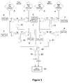
- Fig. 3 shows an example implementation of rollover detection algorithm, according to the present invention.
- the input signals 4 are provided by front and rear tire pressure sensors 3 (cf. Fig.1).
- the operation of the algorithm is realized in two separated, parallel paths, corresponding to front and rear wheels 2 (cf. Fig.1) of the vehicle.
- the algorithm compares all pressure signals 4 with the first threshold 6 (THR_LOW) and the second threshold 7 (THR_HIGH) that is higher than the first threshold, in a manner described below.
- the THR_LOW was set to 2.0 bar, THR_HIGH to 2.4 bar and the nominal pressure P N was 2.2 bar.
- the timer module 15 continuously checks whether the activation conditions are constantly present during predefined time window.
- the timer module 15 starts operating each time the AND gate 14 changed the state to "active" (binary 1), and checks for how long the gate remains active. If left wheels are lifted up and right wheels are loaded for sufficiently long time, the timer module 15 shall transmit the activation signal indicating the right rollover of a vehicle.
- the activation signal varies within the range 0.0 to 1.0 (0-100 %), corresponding to the rollover confidence, proportionally to the duration of the activation state of the gate 14.
- the zero activation signal of the timer 15 denotes lack of activation of the gate 14 and the 100 % activation corresponds to a situation when the gate 14 has been active for 1000 ms
- Activation signal of the timer 15 is the input of the rollover discrimination block 24, which in dependence of the activation signal value deploys an appropriate protection device, which in case the activation signal is greater than 20 % shall be resetable seatbelts, greater than 70% shall be rollover bars and in case the activation signal is greater than 90% shall be airbags.
- the time window of the timer module 15 may be fixed e.g. within the range of about 100 ms to about 1000 ms, in which case only one activation signal shall be provided, or the length of the time window may be dynamically updated during the vehicle operation.
- Such dynamic adjustment may be based on the information about the road surface, driving conditions, averaged value of tire pressures in predefined time window, etc. The purpose of such adjustments is to make the algorithm more or less sensitive, depending on the environment conditions. As a result, better trade off can be achieved between incorrect rollover discrimination, that may result in inadvertent protection device deployment, and either delayed or lack of rollover discrimination.
- the schema corresponding to described above takes place also for left rollover of a vehicle i.e. where right wheels are lifted up and left wheels are loaded, in which case the comparators 16 and 17 and the AND gate 18 corresponding to the front wheels and simultaneously the comparators 19 and 20 and the AND gate 21 become active, thus activating the AND gate 22, output of which is an input of the timer module 23.
- the principle of operation of the timer module 23 is the same as the timer module 15.
- the thresholds 6 (THR_LOW) and 7 (THR_ HIGH) may be constant values or may be dynamically adjusted during operation of the vehicle. Such adjustment allows taking into account the changes of the nominal pressure of each tire, caused e.g. by the temperature influence, as well as velocity of the vehicle, lateral acceleration of the vehicle, weight distribution and other circumstances taking place during the operation of the vehicle.
- the thresholds may also be updated on the base of the tire pressure diagnostic results. Thus, for example, the fact that the tires are not symmetrically filled with the air (different pressures in tires during parking) shall not degrade rollover detection performance.
- Fig. 4 shows another embodiment of a rollover detection algorithm, according to the present invention.
- the input signals 4 of the algorithm are provided by front and rear tire pressure sensors 3 and similarly the algorithm operates in two separated, parallel paths, corresponding to front and rear wheels 2 of the vehicle.
- the pressure assessment is realized in modules 27 and 29 corresponding to the front and rear wheels 2 of the vehicle. Concurrent activation of these two modules leads to activation of AND gate 31, which may deploy an appropriate protection device for the occupant of the vehicle or provide rollover discrimination signal to other car systems.
- the module 27 is comprised of a differential node 33, to which left p L and right p R tire pressure signals are delivered; a block 34 calculating the moving average value of the absolute pressure differences and a comparator 35.
- ⁇ i 0 n d i
- module 29 The principle of operation of the module 29 is similar to that of module 27.
- the analysis of measuring pressure values may comprise comparing course of registered pressure changes against many standard templates of pressure changes courses that characterise many cases of rollover event and generating an output activation signal when registered course of pressure changes corresponds, at required precision, with at least one stored standard course.
- All the standards of pressure changes courses may be stored in the non volatile memory (e.g. EEPROM) of the microcontroller, where algorithm is implemented.
- the length of the time window may be fixed or may be continuously updated by the adaptation algorithm which may take into account many additional conditions, like inequality of weight distribution, tire pressure drop, etc.
- the adaptation algorithm may also limit the number of standards used in the process of comparison in order to make operation of algorithm faster and more reliable.
- Fig. 5 depicts a diagram of an exemplary microcontroller implementation of the invention.
- the required signals are preprocessed in blocks 36 and 37 in order to remove the noise and the pressure signal drift and to perform the low pass filtering.
- Block 36 initiates the first processing path, while the block 37 initiates the second arming path and provides additional signals to block 39.
- Signals of the first path after preprocessing, are delivered to the diagnostic block 38 where they are analysed with respect to their communcation and reliability. If the analysis is negative i.e. one or more signals are out of predefined range, the block 38 disables potential activation of protection devices not transferring the signals or transferring zero signals values for further processing.
- the rollover assessment block 39 estimates the rollover confidence as a value within 0 to 100 %.
- the block 39 may be implemented in manner similar to these described above, with reference to fig. 3 or fig. 4.
- the block 39 comprises four outputs wherein each output corresponds to individual threshold of the rollover confidence in excess of which it becomes active. Exemplary value of these thresholds, depending on the type of protection device, may be 20 % for resetable seatbelts, 70% for rollover bars and 90% for airbags. As shown the rollover discrimination confidence is also delivered to other vehicle systems.
- preprocessed signals like vehicle speed, steering angle value and/or linear acceleration values, are also delivered to the block 39. Owing to this, the value of rollover confidence may be additionally modified for more precise determination of driving conditions.
- block 39 may also detect airborne conditions of the vehicle. As airborne condition (all tires have lost the contact with road surface) is also present during rollover events, additional signals should be used to properly discriminate if airborne or rollover event is present.
- Block 39 can realize more than one independent rollover detection processing paths, for example:
- block 39 can combine tire pressure characteristics with other signals available in the vehicle to make the rollover event prediction more accurate.
- the arming logic 40 may be implemented in many ways which are known for skilled in the art (e.g. disclosed in U.S. Appl. No. 09/769,037).
- lateral and longitudinal high-G accelerometer is present (usually as dual axis device) for detection of side, front and rear impacts to deploy airbags, it is reasonable to use the lateral acceleration exceeding predefined threshold as a minimum arming signal, what can be done at no cost.
- the coincidence of these two conditions is signalled at the outputs of three AND gates 41, 42 and 43 which are connected directly to the particular protection devices 44, 45 and 46.
- all required signals are delivered through the vehicle communication bus 47.
- the presented rollover detection approach may be embodied in all kind of cars, especially in these already equipped with the pressure sensors.
- the costs of such embodiment are relatively low as only an additional microcontroller need to be installed in the system or even at no hardware cost at all if the algorithm is to be implemented in existing microcontroller of the vehicle (e.g. body computer or other ECUs).
- the arrangement of the present invention allows detecting a rollover in an early stage thereof.
Landscapes
- Engineering & Computer Science (AREA)
- Mechanical Engineering (AREA)
- Physics & Mathematics (AREA)
- Automation & Control Theory (AREA)
- Mathematical Physics (AREA)
- Transportation (AREA)
- Air Bags (AREA)
- Control Of Driving Devices And Active Controlling Of Vehicle (AREA)
- Measuring Fluid Pressure (AREA)
Abstract
Description
- The present invention relates to a method and system for detecting a vehicle rollover or near-rollover event that may precede a rollover of a vehicle.
- Systems of this type are used to deploy occupant protection devices such as seat belts pretensioners, pop-up rollover bars or air bags, especially air bags protecting occupants' heads during a rollover accident.
- The majority of the known approaches for detecting vehicle rollover or near-rollover events employ various sensors, signals of which are processed by the rollover algorithm and output activation signal is generated on the basis of the algorithm assessment. Typically the algorithm is implemented as software of the microcontroller, being the part of the same electronic control unit (ECU), that the sensors are installed. Usually the sensors of the ECU include at least one accelerometer, measuring the lateral or vertical acceleration of the vehicle, and angular rate sensor (ARS), measuring the roll rate of the vehicle around its longitudinal axis. These types of systems are often called "Standalone Rollover Detection Modules". Examples of such modules are disclosed in U.S. Pat. 6,433,681, U.S. Pat. 6,535,800, U.S. Appl. No. 10/319,325 or publication WO 03/010034. Other systems, like these disclosed in international publication WO 99/47384 or U.S. Pat. 6,292,759 take an advantage of other signals provided by external sensors already installed in the vehicle, e.g. the vehicle velocity provided by the speedometer, occupant presence signal or steering wheel angle. All these disclosures are incorporated herein by reference and may be used to clarification of certain aspects not described herein in detail.
- The above systems however require at least an ARS sensor which influences the cost of overall system.
- The object of the present invention is to provide an uncomplicated and inexpensive method and system for detecting vehicle rollover or near-rollover event, which in particular employ only the signals from existing vehicle sensors, and which may be easily implemented in existing vehicle microcontroller or other system.
- Another object of the present invention is to provide a method and system for detecting a vehicle rollover or near-rollover event which may be applied as an additional safing or arming system into existing rollover detection arrangements.
- Yet another object of the present invention is to provide a method and system for sequential activation of different types of protection devices, including resetable protection devices (like seatbelt pretensioners or rollover bars) in dependence of estimated rollover confidence.
- According to the present invention there is provided a method of detecting a vehicle rollover or near-rollover event, comprising the steps of measuring the pressures of at least one right vehicle tire and at least one left vehicle tire, performing the assessment of said pressures on the basis of pressure characteristics corresponding to rollover or near-rollover events, and generating output activation signal that determines the vehicle rollover or near-rollover event if said assessment is positive.
- The assessment of said pressures preferably includes comparing each pressure against the first threshold and the second threshold that is higher than the first threshold, and the assessment is positive when simultaneously at least one left tire pressure is below the first threshold and at least one right tire pressure exceeds the second threshold; or if simultaneously at least one right tire pressure is below the first threshold and at least one left tire pressure exceeds the second threshold. Preferably according to the present invention, the conditions of said positive assessment should occur in predefined time window.
- Alternatively the assessment of said pressures beneficially includes measuring a moving average of a number of differences between subsequent left and right tire pressure samples and the assessment is positive when said average exceeds the predefined threshold.
- The assessment of said pressures may also preferably include comparing of the measured pressures characteristics registered in predefined time window against stored pressure templates representing models of rollover or near-rollover events and the assessment is positive if the measured pressures correspond, with predefined precision, to at least one of said templates.
- Stored templates are advantageously obtained by computer simulations, recorded during real rollover events and/or forecasted by experts.
- Prior generating output activation signal the method advantageously comprises the step of performing the additional assessment of at least one other signal on the basis of this signal characteristics corresponding to rollover or near-rollover events.
- Said other signals include vehicle accelerations signals.
- It should be noted that said assessments parameters i.e. thresholds, precision and/or the length of the time window, within which the assessments are performed, may be either fixed or dynamically updated during operation of the vehicle.
- Dynamical updating is advantageously a function of nominal pressure of each tire, low pass filtered pressure of each tire, vehicle velocity, linear acceleration, technical parameters of the vehicle, shape of the pressure plot in predefined time window and/or weight distribution of the vehicle.
- The pressure signals are preferably preprocessed, where preprocessing involves at least low pass filtering, noise removing and pressure signal drift removal.
- The method of the present invention beneficially comprises the additional step of activation of at least one protection device for an occupant of the vehicle, where the signal activating said protection devices may be additionally processed e.g. logically ANDed with another activation signal provided by auxiliary safing algorithm.
- The protection devices may advantageously be activated sequentially, starting with the resetable protection devices, in dependence of estimated rollover confidence.
- According to another aspect of the present invention there is provided a system of detecting a vehicle rollover or near-rollover event, comprising a controller connected to at least one right and at least one left vehicle tire pressure sensor, performing the assessment of pressure signals on the basis of pressure characteristics corresponding to rollover or near-rollover events, and generating an output activation signal that determines the vehicle rollover or near-rollover event if said assessment is positive.
- The controller may be preferably connected to at least one additional sensor and may perform the additional assessment of this sensor signal on the basis of this signal characteristics corresponding to rollover or near-rollover events.
- Said additional sensors beneficially include accelerometer and/or speedometer.
- The system is advantageously connected with at least one protection device for an occupant of a vehicle and said output activation signal is a direct signal to activate said protection devices or is additionally processed before activation of said protection devices.
- Said protection devices may of course be activated sequentially, starting with the resetable protection devices, in dependence of estimated rollover confidence.
- The invention is presented below in details with reference to exemplary embodiments and drawings on which:
- Fig. 1 is a perspective view of a vehicle with the main components of the system according to the present invention;
- Fig. 2a, 2b and 2c are typical time dependent plots of tire pressure fluctuations of a vehicle right and left tires during parking, driving and rollover event respectively;
- Fig. 3 is a block and circuit diagram of one embodiment of the present invention;
- Fig. 4 is a block and circuit diagram of another embodiment of the present invention;
- Fig. 5 is a block and circuit diagram of yet another embodiment of the present invention.
- The general idea of the rollover detection approach, according to the present invention, is illustrated in Fig. 1 which schematically shows a
vehicle body 1. As shown eachtire 2 of the vehicle is coupled withtire pressure sensor 3.Signals 4 ofsensors 3, corresponding to the measuredtire 2 pressures are transmitted to microcontroller 5, where the rollover detection algorithm operates. The microcontroller processes the signals performing their assessment on the basis of pressure characteristics corresponding to rollover or near-rollover events. - An example of
tire pressure sensors 3 are integrated sensors Motorola MPXY8020A, having the dynamic response with respect for changes of the pressure negligible as compared to duration of rollover events; usually in the range of 300 ms (fast rollover event, e.g. curb trip) to 1000 ms (slow rollover event, e.g. fall over into the ditch). The typical range of the tire pressure values available on communication bus (CAN) in case of a motor car is 0 - 4.0 bar with resolution of 0.05 bar, which is even more than sufficient for the purposes of the invention. It is worth noting that many modern vehicles are factory equipped with tire pressure sensors used to detect the puncture of the tire and helping driver to maintain the optimal pressure of tires. Hence it is possible to upgrade the existing vehicle protection systems, already connected with tire pressure sensors by rollover detection approach of the invention, only through the implementation of the algorithm in existing microcontroller. - The rollover assessment includes comparing time-dependent fluctuations of tire pressures with pressure templates stored in library of rollover events, previously forecasted by experts, recorded during real rollover events or being a result of computer simulations; comparing the measured pressures against individually selected thresholds; performing the moving average analysis, and/or performing other types of calculations, selected types of which are described in further part of this document with reference to exemplary embodiments of the invention. In case the assessment is positive, the microcontroller 5 generates an output activation signal, indicating the rollover or near-rollover event, which directly deploys an
appropriate protection device 6 for the occupant of the vehicle and/or is delivered to other electronic systems of the vehicle. - Typical pressure characteristics of vehicle tires, during parking, driving and rollover event are schematically shown in Fig. 2.
- As shown in Fig. 2a, when the car is parked, the pressures in all tires are close to the nominal pressure value PN. The pressures in left and right tires may differ due to the vehicle inclination, inconsistent load of the vehicle, as well as other factors, yet these differences are negligible, as compared to the nominal pressure value PN.
- While the car is driving, the pressure oscillates around the nominal pressure value PN, what is schematically presented in Fig 2b. Obviously, because of road surface, various driver manoeuvres and other dynamical forces the pressures of left and right tires are subjected to slight changes. The pressures vary around the nominal pressure value PN and usually do not take place in longer periods of time. In this example, we may observe that between 0.5 s and 2.0 s the vehicle was driven on bumpy road.
- Exemplary fluctuations of tire pressures during rollover event are presented in Fig. 2c. As shown, the rollover event is characterised in fact that wheels of the same side of the car, in this example left side wheels, are lifted up and consequently the pressure in left tires quickly drops and in short time stabilizes at constant value, which is lower than the nominal pressure PN. At the same time the pressure in remaining right side tires, is higher than the nominal value, as the whole weight of the vehicle is directed into this side of the vehicle. The pressure of right, loaded tires oscillates due to the dynamic nature of the rollover but is larger than the pressure of left, lifted up tires. If increased pressure and/or high-pressure peaks are detected on one side of the vehicle and on the other side the pressure significantly drops, the vehicle is most likely rolling over. This example assumes that there is no pressure drop due to the tire damage like nail or screw in the tire. According to the invention detection of scenarios like slow pressure drop is detected by preprocessing modules. Once unreliable signals are detected, the rollover detection algorithm can be disabled to avoid improper operation.
- Fig. 3 shows an example implementation of rollover detection algorithm, according to the present invention. The input signals 4 are provided by front and rear tire pressure sensors 3 (cf. Fig.1). As shown on Fig. 3, the operation of the algorithm is realized in two separated, parallel paths, corresponding to front and rear wheels 2 (cf. Fig.1) of the vehicle. The algorithm compares all
pressure signals 4 with the first threshold 6 (THR_LOW) and the second threshold 7 (THR_HIGH) that is higher than the first threshold, in a manner described below. - In this embodiment the THR_LOW was set to 2.0 bar, THR_HIGH to 2.4 bar and the nominal pressure PN was 2.2 bar.
- If the left front tire pressure is below the
first threshold 6 and simultaneously the right front tire pressure exceeds thesecond threshold 7 thecomparators gate 10 provides an activation signal. If at the same time left rear tire pressure is below thefirst threshold 6 and simultaneously the right rear tire pressure exceeds thesecond threshold 7 thecomparators gate 13 provides an activation signal. If bothgates gate 14 deploy an activation signal, which is an input of thetimer module 15. - The
timer module 15 continuously checks whether the activation conditions are constantly present during predefined time window. In this example thetimer module 15 starts operating each time the ANDgate 14 changed the state to "active" (binary 1), and checks for how long the gate remains active. If left wheels are lifted up and right wheels are loaded for sufficiently long time, thetimer module 15 shall transmit the activation signal indicating the right rollover of a vehicle. In this embodiment the activation signal varies within the range 0.0 to 1.0 (0-100 %), corresponding to the rollover confidence, proportionally to the duration of the activation state of thegate 14. The zero activation signal of thetimer 15 denotes lack of activation of thegate 14 and the 100 % activation corresponds to a situation when thegate 14 has been active for 1000 ms - Activation signal of the
timer 15 is the input of therollover discrimination block 24, which in dependence of the activation signal value deploys an appropriate protection device, which in case the activation signal is greater than 20 % shall be resetable seatbelts, greater than 70% shall be rollover bars and in case the activation signal is greater than 90% shall be airbags. - It should be understood that the time window of the
timer module 15 may be fixed e.g. within the range of about 100 ms to about 1000 ms, in which case only one activation signal shall be provided, or the length of the time window may be dynamically updated during the vehicle operation. Such dynamic adjustment may be based on the information about the road surface, driving conditions, averaged value of tire pressures in predefined time window, etc. The purpose of such adjustments is to make the algorithm more or less sensitive, depending on the environment conditions. As a result, better trade off can be achieved between incorrect rollover discrimination, that may result in inadvertent protection device deployment, and either delayed or lack of rollover discrimination. - The schema corresponding to described above takes place also for left rollover of a vehicle i.e. where right wheels are lifted up and left wheels are loaded, in which case the
comparators gate 18 corresponding to the front wheels and simultaneously thecomparators gate 21 become active, thus activating the ANDgate 22, output of which is an input of the timer module 23. The principle of operation of the timer module 23 is the same as thetimer module 15. - The thresholds 6 (THR_LOW) and 7 (THR_ HIGH) may be constant values or may be dynamically adjusted during operation of the vehicle. Such adjustment allows taking into account the changes of the nominal pressure of each tire, caused e.g. by the temperature influence, as well as velocity of the vehicle, lateral acceleration of the vehicle, weight distribution and other circumstances taking place during the operation of the vehicle. The thresholds may also be updated on the base of the tire pressure diagnostic results. Thus, for example, the fact that the tires are not symmetrically filled with the air (different pressures in tires during parking) shall not degrade rollover detection performance.
- Fig. 4 shows another embodiment of a rollover detection algorithm, according to the present invention. Similarly as in embodiment of Fig. 3 the input signals 4 of the algorithm are provided by front and rear
tire pressure sensors 3 and similarly the algorithm operates in two separated, parallel paths, corresponding to front andrear wheels 2 of the vehicle. Here the pressure assessment is realized inmodules rear wheels 2 of the vehicle. Concurrent activation of these two modules leads to activation of ANDgate 31, which may deploy an appropriate protection device for the occupant of the vehicle or provide rollover discrimination signal to other car systems. - The
module 27 is comprised of adifferential node 33, to which left pL and right pR tire pressure signals are delivered; ablock 34 calculating the moving average value of the absolute pressure differences and acomparator 35. - The moving average is calculated according to the formula:

where di = (pL - PR) is the pressure difference, n denotes the number of subsequent, backward counted, pressure samples corresponding to the length of the time window in which the pressure differences are calculated, i = 0 is an index of the most recent sample (cf. Fig. 2c). The length of the time window (n) may be individually adjusted for each application and fixed. Otherwise it may be dynamically updated during the operation of the vehicle, taking into account e.g. the vehicle velocity, the vehicle linear acceleration and/or other parameters of the vehicle. In this embodiment n = 500 and the sampling rate is set to 1000Hz. The absolute value of the differences is provided due to the symmetry of the rollover event. Thus contrary to the solution shown in Fig. 3 only two rollover estimation modules are required. If the value d calculated by theblock 34 is greater than the threshold value 30 (AV_THR) thecomparator 35 is activated, indicating that either left or right rollover of the vehicle. - The principle of operation of the
module 29 is similar to that ofmodule 27. - It should be appreciated by persons skilled in the art the above implementations do not require any numerically complicated calculations, or large amount of memory and can be easily realised by means of the few simple logic elements.
- Other implementations of the pressure course analyser, not described in greater details, may base on the shape of the pressure course obtained by registering certain number of consecutive samples forming the time window. In such unit the analysis of measuring pressure values may comprise comparing course of registered pressure changes against many standard templates of pressure changes courses that characterise many cases of rollover event and generating an output activation signal when registered course of pressure changes corresponds, at required precision, with at least one stored standard course. All the standards of pressure changes courses may be stored in the non volatile memory (e.g. EEPROM) of the microcontroller, where algorithm is implemented. The length of the time window may be fixed or may be continuously updated by the adaptation algorithm which may take into account many additional conditions, like inequality of weight distribution, tire pressure drop, etc. The adaptation algorithm may also limit the number of standards used in the process of comparison in order to make operation of algorithm faster and more reliable.
- Fig. 5 depicts a diagram of an exemplary microcontroller implementation of the invention. In the first step of algorithm operation the required signals are preprocessed in
blocks Block 36 initiates the first processing path, while theblock 37 initiates the second arming path and provides additional signals to block 39. - Signals of the first path, after preprocessing, are delivered to the
diagnostic block 38 where they are analysed with respect to their accesibility and reliability. If the analysis is negative i.e. one or more signals are out of predefined range, theblock 38 disables potential activation of protection devices not transferring the signals or transferring zero signals values for further processing. - If the analysis of the
block 38 is positive, signals are delivered to therollover assessment block 39, which estimates the rollover confidence as a value within 0 to 100 %. Theblock 39 may be implemented in manner similar to these described above, with reference to fig. 3 or fig. 4. In this example theblock 39 comprises four outputs wherein each output corresponds to individual threshold of the rollover confidence in excess of which it becomes active. Exemplary value of these thresholds, depending on the type of protection device, may be 20 % for resetable seatbelts, 70% for rollover bars and 90% for airbags. As shown the rollover discrimination confidence is also delivered to other vehicle systems. - Other preprocessed signals, like vehicle speed, steering angle value and/or linear acceleration values, are also delivered to the
block 39. Owing to this, the value of rollover confidence may be additionally modified for more precise determination of driving conditions. - It is also advantageous that
block 39 may also detect airborne conditions of the vehicle. As airborne condition (all tires have lost the contact with road surface) is also present during rollover events, additional signals should be used to properly discriminate if airborne or rollover event is present. -
Block 39 can realize more than one independent rollover detection processing paths, for example: - detection of rollover event on the base of the tire pressure asymmetry, as in case of embodiments presented in Fig. 3 and Fig. 4,
- detection of rollover event on the base of the high lateral acceleration value (e.g. greater than 3g), followed by airborne condition (sudden pressure drop in all tires),
- detection of rollover event on the base of the vertical and/or lateral low-G accelerometer value changes, followed by airborne condition (sudden pressure drop in all tires),
- In general, block 39 can combine tire pressure characteristics with other signals available in the vehicle to make the rollover event prediction more accurate.
- To avoid inadvertent, and in some cases dangerous, activations of protection devices, the activation of each protection device occurs only when, apart from exceeding of rollover confidence threshold, the rollover event occurrence is confirmed by an
additional arming logic 40. The arminglogic 40 may be implemented in many ways which are known for skilled in the art (e.g. disclosed in U.S. Appl. No. 09/769,037). As in almost all modern cars lateral and longitudinal high-G accelerometer is present (usually as dual axis device) for detection of side, front and rear impacts to deploy airbags, it is reasonable to use the lateral acceleration exceeding predefined threshold as a minimum arming signal, what can be done at no cost. The coincidence of these two conditions is signalled at the outputs of three ANDgates particular protection devices - In this example, all required signals (including tire pressure values) are delivered through the
vehicle communication bus 47. - The presented rollover detection approach may be embodied in all kind of cars, especially in these already equipped with the pressure sensors. The costs of such embodiment are relatively low as only an additional microcontroller need to be installed in the system or even at no hardware cost at all if the algorithm is to be implemented in existing microcontroller of the vehicle (e.g. body computer or other ECUs). The arrangement of the present invention allows detecting a rollover in an early stage thereof.
- It is obvious that many parameters and factors need to be properly chosen in order to implement the rollover detection system according to the present invention in a given vehicle. Such factors include but not limit to the weight, geometry and type of the vehicle, installed protection devices, centre of gravity and presence of other rollover detection systems, in which case the system of the invention may operate merely as auxiliary safing logic. These and other factors however should not be considered as limiting the spirit of the invention, the intended scope of protection of which is indicated in appended claims.
Claims (24)
- A method of detecting a vehicle rollover or near-rollover event, characterised in that it comprises the steps of measuring the pressures of at least one right vehicle tire and at least one left vehicle tire, performing the assessment of said pressures on the basis of pressure characteristics corresponding to rollover or near-rollover events, and generating output activation signal that determines the vehicle rollover or near-rollover event if said assessment is positive.
- A method as claimed in claim 1, characterised in that said assessment of said pressures includes comparing each pressure against the first threshold and the second threshold that is higher than the first threshold, and the assessment is positive when simultaneously at least one left tire pressure is below the first threshold and at least one right tire pressure exceeds the second threshold; or if simultaneously at least one right tire pressure is below the first threshold and at least one left tire pressure exceeds the second threshold.
- A method as claimed in claim 2, characterised in that the conditions of said positive assessment must be present in predefined time window.
- A method as claimed in claim 1, characterised in that said assessment of said pressures includes measuring a moving average of a number of differences between subsequent left and right tire pressure samples and the assessment is positive when said average exceeds the predefined threshold.
- A method as claimed in claim 1, characterised in that said assessment of said pressures includes comparing of the measured pressures characteristics registered in predefined time window against stored pressure templates representing models of rollover or near-rollover events and the assessment is positive if the measured pressures characteristic correspond, with predefined precision, to at least one of said templates.
- A method as claimed in claim 5, characterised in that said stored templates are obtained by computer simulations, recorded during real rollover events and/or forecasted by experts.
- A method as claimed in any of above claims, characterised in that prior generating output activation it comprises the step of performing the assessment of at least one additional signal on the basis of this signal characteristics corresponding to rollover or near-rollover events.
- A method as claimed in claim 7, characterised in that said additional signals include vehicle accelerations signals and vehicle speed.
- A method as claimed in any of above claims, characterised in that said assessments parameters are dynamically updated during operation of the vehicle.
- A method as claimed in claim 9, characterised in that dynamical updating is a function of at least one parameter chosen from nominal pressure of each tire determined as an average pressure value in predefined time window, vehicle velocity, history of the tire pressure values, linear acceleration and weight distribution of the vehicle.
- A method as claimed in any of above claims, characterised in that signals are preprocessed.
- A method as claimed in claim 11, characterised in that the preprocessing involves at least low pass filtering, noise and pressure signal drift removal.
- A method as claimed in any of above claims, characterised in that, it further comprises the step of activation at least one protection device for an occupant of the vehicle.
- A method as claimed in claim. 13, characterised in that, said output activation signal is additionally processed before activation of said protection devices.
- A method as claimed in claim. 13, characterised in that, protection devices are activated sequentially, starting with the resetable protection devices, in dependence of estimated rollover confidence.
- A system for detecting a vehicle rollover or near-rollover event, characterised in that, it comprises controller connected to at least one right and at least one left vehicle tire pressure sensor, performing the assessment of pressure signals on the basis of pressure characteristics corresponding to rollover or near-rollover events, and generating an output activation signal that determines the vehicle rollover or near-rollover event if said assessment is positive.
- A system as claimed in claim 16, characterised in that the controller is connected to at least one additional sensor and performs the assessment of this sensor signal on the basis of this signal characteristics corresponding to rollover or near-rollover events.
- A method as claimed in claim 17, characterised in that said additional sensors include accelerometer and/or speedometer.
- A system as claimed in any of above claims, characterised in that sensor signals are preprocessed.
- A system as claimed in claim 19, characterised in that the preprocessing involves at least low pass filtering, noise removing and drift removal.
- A system as claimed in any of above claims, characterised in that, it is connected with at least one protection device for an occupant of a vehicle.
- A system as claimed in claim. 21, characterised in that, said output activation signal is additionally processed before activation of said protection devices.
- A system as claimed in claim. 21, characterised in that, said output activation signal is a signal to activate said protection devices.
- A system as claimed in claim. 21, characterised in that, protection devices are activated sequentially, starting with the resetable protection devices, in dependence of estimated rollover confidence.
Priority Applications (4)
| Application Number | Priority Date | Filing Date | Title |
|---|---|---|---|
| EP04460031A EP1619083B1 (en) | 2004-07-19 | 2004-07-19 | A method and system for detecting vehicle rollover events |
| DE602004013303T DE602004013303T2 (en) | 2004-07-19 | 2004-07-19 | A method and system for detecting a vehicle rollover condition |
| AT04460031T ATE393064T1 (en) | 2004-07-19 | 2004-07-19 | A METHOD AND SYSTEM FOR DETECTING A VEHICLE ROLL CONDITION |
| US11/178,901 US7422087B2 (en) | 2004-07-19 | 2005-07-11 | Method and system for detecting vehicle rollover events |
Applications Claiming Priority (1)
| Application Number | Priority Date | Filing Date | Title |
|---|---|---|---|
| EP04460031A EP1619083B1 (en) | 2004-07-19 | 2004-07-19 | A method and system for detecting vehicle rollover events |
Publications (2)
| Publication Number | Publication Date |
|---|---|
| EP1619083A1 true EP1619083A1 (en) | 2006-01-25 |
| EP1619083B1 EP1619083B1 (en) | 2008-04-23 |
Family
ID=34933172
Family Applications (1)
| Application Number | Title | Priority Date | Filing Date |
|---|---|---|---|
| EP04460031A Expired - Lifetime EP1619083B1 (en) | 2004-07-19 | 2004-07-19 | A method and system for detecting vehicle rollover events |
Country Status (4)
| Country | Link |
|---|---|
| US (1) | US7422087B2 (en) |
| EP (1) | EP1619083B1 (en) |
| AT (1) | ATE393064T1 (en) |
| DE (1) | DE602004013303T2 (en) |
Cited By (2)
| Publication number | Priority date | Publication date | Assignee | Title |
|---|---|---|---|---|
| KR100892817B1 (en) * | 2007-11-13 | 2009-04-10 | 현대자동차주식회사 | Method for controlling air-bag by using tire pressure monitoring system |
| EP2657089A1 (en) * | 2012-04-24 | 2013-10-30 | Autoliv Development AB | A vehicle safety system |
Families Citing this family (16)
| Publication number | Priority date | Publication date | Assignee | Title |
|---|---|---|---|---|
| ATE393064T1 (en) * | 2004-07-19 | 2008-05-15 | Delphi Tech Inc | A METHOD AND SYSTEM FOR DETECTING A VEHICLE ROLL CONDITION |
| US7805231B2 (en) * | 2006-06-29 | 2010-09-28 | Delphi Technologies, Inc. | Integrated vehicle crash sensing system and method |
| US7873449B2 (en) * | 2007-03-29 | 2011-01-18 | Ford Global Technologies | Vehicle safety system with advanced tire monitoring |
| US7778741B2 (en) * | 2007-03-29 | 2010-08-17 | Ford Global Technologies | Vehicle stability control system with tire monitoring |
| US8032281B2 (en) | 2007-03-29 | 2011-10-04 | Ford Global Technologies | Vehicle control system with advanced tire monitoring |
| US8086376B2 (en) * | 2007-10-10 | 2011-12-27 | Ford Global Technologies Llc | Vehicle rollover prediction with occupant restraint system activation |
| JP2010040994A (en) * | 2008-08-08 | 2010-02-18 | Toshiba Corp | Semiconductor memory device, and method of manufacturing the same |
| US8275516B2 (en) | 2009-07-21 | 2012-09-25 | Trimble Navigation Limited | Agricultural vehicle autopilot rollover risk assessment system |
| US8843269B2 (en) * | 2011-08-17 | 2014-09-23 | Deere & Company | Vehicle soil pressure management based on topography |
| DE102011084880B4 (en) * | 2011-10-20 | 2016-12-15 | Robert Bosch Gmbh | A method of generating a free flight advisory information for a vehicle and a method of detecting a free flight condition of a vehicle |
| DE102011084877B3 (en) * | 2011-10-20 | 2012-12-27 | Robert Bosch Gmbh | Method for creating free flight reference information for e.g. passenger car, involves generating free flight reference information based on comparison of course of seat occupancy signal with reference course for seat occupancy signal |
| DE102011084842B4 (en) | 2011-10-20 | 2017-12-14 | Robert Bosch Gmbh | A method of generating a free flight advisory information for a vehicle and a method of detecting a free flight condition of a vehicle |
| US9925867B2 (en) | 2016-01-11 | 2018-03-27 | Ford Global Technologies, Llc | Fuel control regulator system with acoustic pliability |
| US10017142B2 (en) | 2016-09-12 | 2018-07-10 | Ford Global Technologies, Llc | Filtration of acoustic contaminate from vehicle safety sensors |
| US10354459B2 (en) | 2016-10-06 | 2019-07-16 | Ford Global Technologies, Llc | Hydrocarbon-emissions monitoring |
| DE102022211990A1 (en) | 2022-11-11 | 2024-05-16 | Zf Friedrichshafen Ag | Method and control device for operating a self-propelled work machine |
Citations (4)
| Publication number | Priority date | Publication date | Assignee | Title |
|---|---|---|---|---|
| DE10015267A1 (en) * | 2000-03-28 | 2001-10-25 | Siemens Ag | Motor vehicle occupant protection device control system - uses evaluation unit provided with devices for calculating positional changes of vehicle from measurement data supplied from sensors at vehicle wheels |
| US20020014767A1 (en) * | 1999-12-01 | 2002-02-07 | Trw Occupant Restraint Systems Gmbh & Co. Kg | Vehicle occupant restraint system |
| US20030149530A1 (en) * | 2002-02-01 | 2003-08-07 | Ford Global Technologies, Inc. | Collision warning and safety countermeasure system |
| DE10234593A1 (en) * | 2002-07-30 | 2004-02-19 | Robert Bosch Gmbh | Device for detecting vehicle rollover, uses inertial sensor signals to check plausibility of rollover detection using signals of tire sensors in form of pressure, temperature or revolution rate sensors |
Family Cites Families (19)
| Publication number | Priority date | Publication date | Assignee | Title |
|---|---|---|---|---|
| US7596242B2 (en) * | 1995-06-07 | 2009-09-29 | Automotive Technologies International, Inc. | Image processing for vehicular applications |
| GB2335522B (en) | 1998-03-17 | 2002-06-05 | Autoliv Dev | Improvements in or relating to a safety arrangement |
| US6292759B1 (en) * | 1998-11-19 | 2001-09-18 | Delphi Technologies, Inc. | Vehicle attitude angle estimation using sensed signal blending |
| US6433681B1 (en) * | 2000-12-20 | 2002-08-13 | Trw Inc. | Apparatus and method for detecting vehicle rollover having roll-rate switched threshold |
| US6535800B2 (en) * | 2001-05-29 | 2003-03-18 | Delphi Technologies, Inc. | Vehicle rollover sensing using angular rate sensors |
| JP3608050B2 (en) | 2001-07-24 | 2005-01-05 | トヨタ自動車株式会社 | Rollover discrimination device |
| US20040024505A1 (en) * | 2002-08-05 | 2004-02-05 | Salib Albert Chenouda | System and method for operating a rollover control system in a transition to a rollover condition |
| JP4193971B2 (en) * | 2002-09-10 | 2008-12-10 | 株式会社アドヴィックス | Vehicle motion control device |
| JP4427964B2 (en) * | 2003-03-31 | 2010-03-10 | 株式会社アドヴィックス | Vehicle control device |
| DE10320828A1 (en) * | 2003-05-08 | 2004-12-09 | Robert Bosch Gmbh | Optimization of vehicle dynamics control using tire information |
| EP1642108B1 (en) * | 2003-07-04 | 2010-01-20 | Pirelli Tyre S.p.A. | Method and system for determining a tyre load during the running of a motor vehicle |
| US20050033549A1 (en) * | 2003-07-25 | 2005-02-10 | Siemens Vdo Automotive Corporation | Rollover sensing using tire pressure sensor |
| US7197388B2 (en) * | 2003-11-06 | 2007-03-27 | Ford Global Technologies, Llc | Roll stability control system for an automotive vehicle using an external environmental sensing system |
| US7206679B2 (en) * | 2004-01-08 | 2007-04-17 | Delphi Technologies, Inc. | Reconfigurable methodology for event detection in a motor vehicle |
| ATE393064T1 (en) * | 2004-07-19 | 2008-05-15 | Delphi Tech Inc | A METHOD AND SYSTEM FOR DETECTING A VEHICLE ROLL CONDITION |
| US7269483B2 (en) * | 2004-08-19 | 2007-09-11 | Delphi Technologies, Inc. | Multiple algorithm event discrimination method |
| US7162343B2 (en) * | 2004-09-17 | 2007-01-09 | Ford Global Technologies, Llc | Intelligent vehicle rollover detection methods and systems |
| US20060267750A1 (en) * | 2005-05-26 | 2006-11-30 | Ford Global Technologies, Llc | Tire abnormal state monitoring system for an automotive vehicle |
| US7925412B2 (en) * | 2006-05-02 | 2011-04-12 | Bendix Commercial Vehicle Systems Llc | Vehicle stability system with multiple sensitivities |
-
2004
- 2004-07-19 AT AT04460031T patent/ATE393064T1/en not_active IP Right Cessation
- 2004-07-19 DE DE602004013303T patent/DE602004013303T2/en not_active Expired - Lifetime
- 2004-07-19 EP EP04460031A patent/EP1619083B1/en not_active Expired - Lifetime
-
2005
- 2005-07-11 US US11/178,901 patent/US7422087B2/en active Active
Patent Citations (4)
| Publication number | Priority date | Publication date | Assignee | Title |
|---|---|---|---|---|
| US20020014767A1 (en) * | 1999-12-01 | 2002-02-07 | Trw Occupant Restraint Systems Gmbh & Co. Kg | Vehicle occupant restraint system |
| DE10015267A1 (en) * | 2000-03-28 | 2001-10-25 | Siemens Ag | Motor vehicle occupant protection device control system - uses evaluation unit provided with devices for calculating positional changes of vehicle from measurement data supplied from sensors at vehicle wheels |
| US20030149530A1 (en) * | 2002-02-01 | 2003-08-07 | Ford Global Technologies, Inc. | Collision warning and safety countermeasure system |
| DE10234593A1 (en) * | 2002-07-30 | 2004-02-19 | Robert Bosch Gmbh | Device for detecting vehicle rollover, uses inertial sensor signals to check plausibility of rollover detection using signals of tire sensors in form of pressure, temperature or revolution rate sensors |
Cited By (2)
| Publication number | Priority date | Publication date | Assignee | Title |
|---|---|---|---|---|
| KR100892817B1 (en) * | 2007-11-13 | 2009-04-10 | 현대자동차주식회사 | Method for controlling air-bag by using tire pressure monitoring system |
| EP2657089A1 (en) * | 2012-04-24 | 2013-10-30 | Autoliv Development AB | A vehicle safety system |
Also Published As
| Publication number | Publication date |
|---|---|
| US7422087B2 (en) | 2008-09-09 |
| US20060027412A1 (en) | 2006-02-09 |
| DE602004013303T2 (en) | 2009-05-14 |
| ATE393064T1 (en) | 2008-05-15 |
| DE602004013303D1 (en) | 2008-06-05 |
| EP1619083B1 (en) | 2008-04-23 |
Similar Documents
| Publication | Publication Date | Title |
|---|---|---|
| US7422087B2 (en) | Method and system for detecting vehicle rollover events | |
| EP1101658B1 (en) | System and method for detecting the onset of a vehicle rollover | |
| EP1754633B1 (en) | Vehicle rollover detection apparatus and method | |
| JP4053789B2 (en) | Vehicle rollover detection system | |
| US7162343B2 (en) | Intelligent vehicle rollover detection methods and systems | |
| US7206680B2 (en) | Method for determining a decision for the triggering of restraint means in a vehicle | |
| EP1783008B1 (en) | Collision determination system for vehicle | |
| US7499779B2 (en) | Method and system for detecting a vehicle rollover | |
| US20090150021A1 (en) | Methods for Detecting Vehicle Rollover | |
| US9085286B2 (en) | Triggering method for activating a lateral velocity estimating system for occupant protection devices | |
| US8744690B2 (en) | Method for determining a criterion of the severity of an accident by means of an acceleration signal and a solid-borne sound signal | |
| US7349783B2 (en) | Supplemental restraint deployment method with anticipatory crash classification | |
| EP2289753A1 (en) | Method and control device for detecting and/or plausibilizing an airborne situation of a vehicle | |
| US8433480B2 (en) | Method and device for triggering personal protection means during a rollover accident | |
| US8244437B2 (en) | Method and system for restraint deployment using lateral kinetic energy | |
| EP2020338B1 (en) | A method and system for detecting a vehicle rollover, in particular a soil trip rollover | |
| RU2748525C2 (en) | Method for activating at least one secondary function of the vehicle passenger protection system | |
| JP2008528377A (en) | Safety system | |
| US6640176B2 (en) | Method for deploying a restraint system | |
| CN112172724A (en) | Method for detonating an airbag | |
| KR100362098B1 (en) | Collision detecting method for operating automobile air bag | |
| WO2002024489A1 (en) | A crash assessment and classification device | |
| KR20060033825A (en) | Air-bag's control method | |
| KR20060016409A (en) | Air-bag's control method |
Legal Events
| Date | Code | Title | Description |
|---|---|---|---|
| PUAI | Public reference made under article 153(3) epc to a published international application that has entered the european phase |
Free format text: ORIGINAL CODE: 0009012 |
|
| AK | Designated contracting states |
Kind code of ref document: A1 Designated state(s): AT BE BG CH CY CZ DE DK EE ES FI FR GB GR HU IE IT LI LU MC NL PL PT RO SE SI SK TR |
|
| AX | Request for extension of the european patent |
Extension state: AL HR LT LV MK |
|
| 17P | Request for examination filed |
Effective date: 20060725 |
|
| AKX | Designation fees paid |
Designated state(s): AT BE BG CH CY CZ DE DK EE ES FI FR GB GR HU IE IT LI LU MC NL PL PT RO SE SI SK TR |
|
| GRAP | Despatch of communication of intention to grant a patent |
Free format text: ORIGINAL CODE: EPIDOSNIGR1 |
|
| GRAS | Grant fee paid |
Free format text: ORIGINAL CODE: EPIDOSNIGR3 |
|
| GRAA | (expected) grant |
Free format text: ORIGINAL CODE: 0009210 |
|
| AK | Designated contracting states |
Kind code of ref document: B1 Designated state(s): AT BE BG CH CY CZ DE DK EE ES FI FR GB GR HU IE IT LI LU MC NL PL PT RO SE SI SK TR |
|
| REG | Reference to a national code |
Ref country code: GB Ref legal event code: FG4D |
|
| REG | Reference to a national code |
Ref country code: CH Ref legal event code: EP |
|
| REF | Corresponds to: |
Ref document number: 602004013303 Country of ref document: DE Date of ref document: 20080605 Kind code of ref document: P |
|
| REG | Reference to a national code |
Ref country code: IE Ref legal event code: FG4D Free format text: LANGUAGE OF EP DOCUMENT: FRENCH |
|
| REG | Reference to a national code |
Ref country code: SE Ref legal event code: TRGR |
|
| PG25 | Lapsed in a contracting state [announced via postgrant information from national office to epo] |
Ref country code: SI Free format text: LAPSE BECAUSE OF FAILURE TO SUBMIT A TRANSLATION OF THE DESCRIPTION OR TO PAY THE FEE WITHIN THE PRESCRIBED TIME-LIMIT Effective date: 20080423 |
|
| NLV1 | Nl: lapsed or annulled due to failure to fulfill the requirements of art. 29p and 29m of the patents act | ||
| PG25 | Lapsed in a contracting state [announced via postgrant information from national office to epo] |
Ref country code: ES Free format text: LAPSE BECAUSE OF FAILURE TO SUBMIT A TRANSLATION OF THE DESCRIPTION OR TO PAY THE FEE WITHIN THE PRESCRIBED TIME-LIMIT Effective date: 20080803 Ref country code: BG Free format text: LAPSE BECAUSE OF FAILURE TO SUBMIT A TRANSLATION OF THE DESCRIPTION OR TO PAY THE FEE WITHIN THE PRESCRIBED TIME-LIMIT Effective date: 20080723 Ref country code: PT Free format text: LAPSE BECAUSE OF FAILURE TO SUBMIT A TRANSLATION OF THE DESCRIPTION OR TO PAY THE FEE WITHIN THE PRESCRIBED TIME-LIMIT Effective date: 20080923 Ref country code: NL Free format text: LAPSE BECAUSE OF FAILURE TO SUBMIT A TRANSLATION OF THE DESCRIPTION OR TO PAY THE FEE WITHIN THE PRESCRIBED TIME-LIMIT Effective date: 20080423 Ref country code: FI Free format text: LAPSE BECAUSE OF FAILURE TO SUBMIT A TRANSLATION OF THE DESCRIPTION OR TO PAY THE FEE WITHIN THE PRESCRIBED TIME-LIMIT Effective date: 20080423 |
|
| ET | Fr: translation filed | ||
| PG25 | Lapsed in a contracting state [announced via postgrant information from national office to epo] |
Ref country code: AT Free format text: LAPSE BECAUSE OF FAILURE TO SUBMIT A TRANSLATION OF THE DESCRIPTION OR TO PAY THE FEE WITHIN THE PRESCRIBED TIME-LIMIT Effective date: 20080423 Ref country code: PL Free format text: LAPSE BECAUSE OF FAILURE TO SUBMIT A TRANSLATION OF THE DESCRIPTION OR TO PAY THE FEE WITHIN THE PRESCRIBED TIME-LIMIT Effective date: 20080423 |
|
| PG25 | Lapsed in a contracting state [announced via postgrant information from national office to epo] |
Ref country code: DK Free format text: LAPSE BECAUSE OF FAILURE TO SUBMIT A TRANSLATION OF THE DESCRIPTION OR TO PAY THE FEE WITHIN THE PRESCRIBED TIME-LIMIT Effective date: 20080423 Ref country code: CZ Free format text: LAPSE BECAUSE OF FAILURE TO SUBMIT A TRANSLATION OF THE DESCRIPTION OR TO PAY THE FEE WITHIN THE PRESCRIBED TIME-LIMIT Effective date: 20080423 |
|
| PG25 | Lapsed in a contracting state [announced via postgrant information from national office to epo] |
Ref country code: SK Free format text: LAPSE BECAUSE OF FAILURE TO SUBMIT A TRANSLATION OF THE DESCRIPTION OR TO PAY THE FEE WITHIN THE PRESCRIBED TIME-LIMIT Effective date: 20080423 Ref country code: RO Free format text: LAPSE BECAUSE OF FAILURE TO SUBMIT A TRANSLATION OF THE DESCRIPTION OR TO PAY THE FEE WITHIN THE PRESCRIBED TIME-LIMIT Effective date: 20080423 Ref country code: BE Free format text: LAPSE BECAUSE OF FAILURE TO SUBMIT A TRANSLATION OF THE DESCRIPTION OR TO PAY THE FEE WITHIN THE PRESCRIBED TIME-LIMIT Effective date: 20080423 |
|
| PLBE | No opposition filed within time limit |
Free format text: ORIGINAL CODE: 0009261 |
|
| REG | Reference to a national code |
Ref country code: CH Ref legal event code: PL |
|
| STAA | Information on the status of an ep patent application or granted ep patent |
Free format text: STATUS: NO OPPOSITION FILED WITHIN TIME LIMIT |
|
| GBPC | Gb: european patent ceased through non-payment of renewal fee |
Effective date: 20080723 |
|
| PG25 | Lapsed in a contracting state [announced via postgrant information from national office to epo] |
Ref country code: MC Free format text: LAPSE BECAUSE OF NON-PAYMENT OF DUE FEES Effective date: 20080731 |
|
| 26N | No opposition filed |
Effective date: 20090126 |
|
| PG25 | Lapsed in a contracting state [announced via postgrant information from national office to epo] |
Ref country code: EE Free format text: LAPSE BECAUSE OF FAILURE TO SUBMIT A TRANSLATION OF THE DESCRIPTION OR TO PAY THE FEE WITHIN THE PRESCRIBED TIME-LIMIT Effective date: 20080423 |
|
| PG25 | Lapsed in a contracting state [announced via postgrant information from national office to epo] |
Ref country code: GB Free format text: LAPSE BECAUSE OF NON-PAYMENT OF DUE FEES Effective date: 20080723 Ref country code: CH Free format text: LAPSE BECAUSE OF NON-PAYMENT OF DUE FEES Effective date: 20080731 Ref country code: LI Free format text: LAPSE BECAUSE OF NON-PAYMENT OF DUE FEES Effective date: 20080731 |
|
| PG25 | Lapsed in a contracting state [announced via postgrant information from national office to epo] |
Ref country code: IE Free format text: LAPSE BECAUSE OF NON-PAYMENT OF DUE FEES Effective date: 20080719 |
|
| PG25 | Lapsed in a contracting state [announced via postgrant information from national office to epo] |
Ref country code: IT Free format text: LAPSE BECAUSE OF FAILURE TO SUBMIT A TRANSLATION OF THE DESCRIPTION OR TO PAY THE FEE WITHIN THE PRESCRIBED TIME-LIMIT Effective date: 20080423 |
|
| PG25 | Lapsed in a contracting state [announced via postgrant information from national office to epo] |
Ref country code: CY Free format text: LAPSE BECAUSE OF FAILURE TO SUBMIT A TRANSLATION OF THE DESCRIPTION OR TO PAY THE FEE WITHIN THE PRESCRIBED TIME-LIMIT Effective date: 20080423 Ref country code: LU Free format text: LAPSE BECAUSE OF NON-PAYMENT OF DUE FEES Effective date: 20080719 Ref country code: HU Free format text: LAPSE BECAUSE OF FAILURE TO SUBMIT A TRANSLATION OF THE DESCRIPTION OR TO PAY THE FEE WITHIN THE PRESCRIBED TIME-LIMIT Effective date: 20081024 |
|
| PG25 | Lapsed in a contracting state [announced via postgrant information from national office to epo] |
Ref country code: TR Free format text: LAPSE BECAUSE OF FAILURE TO SUBMIT A TRANSLATION OF THE DESCRIPTION OR TO PAY THE FEE WITHIN THE PRESCRIBED TIME-LIMIT Effective date: 20080423 |
|
| PG25 | Lapsed in a contracting state [announced via postgrant information from national office to epo] |
Ref country code: GR Free format text: LAPSE BECAUSE OF FAILURE TO SUBMIT A TRANSLATION OF THE DESCRIPTION OR TO PAY THE FEE WITHIN THE PRESCRIBED TIME-LIMIT Effective date: 20080724 |
|
| REG | Reference to a national code |
Ref country code: DE Ref legal event code: R082 Ref document number: 602004013303 Country of ref document: DE Representative=s name: GRUENECKER, KINKELDEY, STOCKMAIR & SCHWANHAEUS, DE |
|
| REG | Reference to a national code |
Ref country code: DE Ref legal event code: R082 Ref document number: 602004013303 Country of ref document: DE Representative=s name: GRUENECKER, KINKELDEY, STOCKMAIR & SCHWANHAEUS, DE Effective date: 20140722 Ref country code: DE Ref legal event code: R081 Ref document number: 602004013303 Country of ref document: DE Owner name: SAMSUNG ELECTRONICS CO., LTD., SUWON-SI, KR Free format text: FORMER OWNER: DELPHI TECHNOLOGIES, INC., TROY, MICH., US Effective date: 20140722 Ref country code: DE Ref legal event code: R082 Ref document number: 602004013303 Country of ref document: DE Representative=s name: GRUENECKER PATENT- UND RECHTSANWAELTE PARTG MB, DE Effective date: 20140722 |
|
| REG | Reference to a national code |
Ref country code: FR Ref legal event code: TP Owner name: SAMSUNG ELECTRONICS CO., LTD., KR Effective date: 20140910 |
|
| REG | Reference to a national code |
Ref country code: FR Ref legal event code: PLFP Year of fee payment: 12 |
|
| REG | Reference to a national code |
Ref country code: FR Ref legal event code: PLFP Year of fee payment: 13 |
|
| REG | Reference to a national code |
Ref country code: FR Ref legal event code: PLFP Year of fee payment: 14 |
|
| REG | Reference to a national code |
Ref country code: FR Ref legal event code: PLFP Year of fee payment: 15 |
|
| PGFP | Annual fee paid to national office [announced via postgrant information from national office to epo] |
Ref country code: FR Payment date: 20230621 Year of fee payment: 20 |
|
| PGFP | Annual fee paid to national office [announced via postgrant information from national office to epo] |
Ref country code: SE Payment date: 20230621 Year of fee payment: 20 |
|
| PGFP | Annual fee paid to national office [announced via postgrant information from national office to epo] |
Ref country code: DE Payment date: 20230620 Year of fee payment: 20 |
|
| REG | Reference to a national code |
Ref country code: DE Ref legal event code: R071 Ref document number: 602004013303 Country of ref document: DE |
|
| REG | Reference to a national code |
Ref country code: SE Ref legal event code: EUG |