EP1619073A1 - Dispositif de bras articulé à plusieurs mouvements notamment pour l'aide à la manutention - Google Patents
Dispositif de bras articulé à plusieurs mouvements notamment pour l'aide à la manutention Download PDFInfo
- Publication number
- EP1619073A1 EP1619073A1 EP05106769A EP05106769A EP1619073A1 EP 1619073 A1 EP1619073 A1 EP 1619073A1 EP 05106769 A EP05106769 A EP 05106769A EP 05106769 A EP05106769 A EP 05106769A EP 1619073 A1 EP1619073 A1 EP 1619073A1
- Authority
- EP
- European Patent Office
- Prior art keywords
- arm
- axis
- rotation
- frame
- translation
- Prior art date
- Legal status (The legal status is an assumption and is not a legal conclusion. Google has not performed a legal analysis and makes no representation as to the accuracy of the status listed.)
- Granted
Links
- 230000002441 reversible effect Effects 0.000 claims description 5
- 230000000903 blocking effect Effects 0.000 claims description 2
- 239000004570 mortar (masonry) Substances 0.000 description 3
- 230000000694 effects Effects 0.000 description 2
- 239000000463 material Substances 0.000 description 2
- 208000010543 22q11.2 deletion syndrome Diseases 0.000 description 1
- 238000006073 displacement reaction Methods 0.000 description 1
- 238000012797 qualification Methods 0.000 description 1
- 230000000284 resting effect Effects 0.000 description 1
Images


Classifications
-
- F—MECHANICAL ENGINEERING; LIGHTING; HEATING; WEAPONS; BLASTING
- F41—WEAPONS
- F41A—FUNCTIONAL FEATURES OR DETAILS COMMON TO BOTH SMALLARMS AND ORDNANCE, e.g. CANNONS; MOUNTINGS FOR SMALLARMS OR ORDNANCE
- F41A9/00—Feeding or loading of ammunition; Magazines; Guiding means for the extracting of cartridges
- F41A9/38—Loading arrangements, i.e. for bringing the ammunition into the firing position
-
- B—PERFORMING OPERATIONS; TRANSPORTING
- B60—VEHICLES IN GENERAL
- B60P—VEHICLES ADAPTED FOR LOAD TRANSPORTATION OR TO TRANSPORT, TO CARRY, OR TO COMPRISE SPECIAL LOADS OR OBJECTS
- B60P1/00—Vehicles predominantly for transporting loads and modified to facilitate loading, consolidating the load, or unloading
- B60P1/48—Vehicles predominantly for transporting loads and modified to facilitate loading, consolidating the load, or unloading using pivoted arms raisable above load-transporting element
-
- F—MECHANICAL ENGINEERING; LIGHTING; HEATING; WEAPONS; BLASTING
- F41—WEAPONS
- F41A—FUNCTIONAL FEATURES OR DETAILS COMMON TO BOTH SMALLARMS AND ORDNANCE, e.g. CANNONS; MOUNTINGS FOR SMALLARMS OR ORDNANCE
- F41A15/00—Cartridge extractors, i.e. devices for pulling cartridges or cartridge cases at least partially out of the cartridge chamber; Cartridge ejectors, i.e. devices for throwing the extracted cartridges or cartridge cases free of the gun
- F41A15/22—Tools for extracting cartridges
-
- F—MECHANICAL ENGINEERING; LIGHTING; HEATING; WEAPONS; BLASTING
- F41—WEAPONS
- F41A—FUNCTIONAL FEATURES OR DETAILS COMMON TO BOTH SMALLARMS AND ORDNANCE, e.g. CANNONS; MOUNTINGS FOR SMALLARMS OR ORDNANCE
- F41A9/00—Feeding or loading of ammunition; Magazines; Guiding means for the extracting of cartridges
- F41A9/87—Ammunition handling dollies or transfer carts
Definitions
- the present invention relates to a multi-motion articulated arm device. It applies in particular for handling objects in a translational movement and a rotational movement.
- the devices for handling the articulated arm are used in particular for moving, loading or unloading heavy or bulky equipment. It is known to produce articulated arms with several movements, for example in translation and in rotation. These arms are made using a motor auxiliary for each movement, which requires in particular a controller and multichannel distributors. They are therefore relatively complex and expensive systems. By way of example, mention may be made of mechanical machines of the backhoe or crane type. The complexity of these systems makes them otherwise slow and possibly unsafe. They are also not very easy to use and bulky. Except, some applications require speed and safety of handling and a simplification of use of the articulated arms. An example of an application is the loading and unloading of a mortar of a vehicle with the simplest and fastest maneuver possible.
- the frame may comprise a slot parallel to the direction of translation, a lug integral with the translational part being engaged in the slot, the stroke of the part being blocked when the lug reaches the end of the slot.
- the device comprises a system locking the position of the part when it reaches its end of travel in translation.
- This locking system is for example a return spring latch pivoting about an axis blocking the lug.
- the arm comprises for example a protrusion resting on the latch when the arm folds on the part 4 by a reverse rotation movement.
- the protuberance on the frame is for example a ramp.
- the mechanically secured element of the arm is for example a roller or roller coming to roll on this ramp.
- the arm comprises for example at least two branches connected by at least two mechanical axes, one of which passes through the workpiece to form an axis of rotation relative to the workpiece.
- the other mechanical axis causes the element to rise on the protuberance.
- the part in translation is for example a slider moving in a tube of the frame
- the protuberance is for example a slope made on the tube.
- the engine auxiliary is for example a cylinder or a worm.
- the main advantages of the invention are that it makes it possible to obtain an articulated arm which is simple to handle, quick and safe to use, compact and economical.
- Figure 1 shows in perspective a possible embodiment of the device according to the invention.
- the device is represented in closed or initial position. It comprises two tilting branches 10 connected by at least two mechanical axes 2, 3, the assembly forming a single mechanical structure 1 hereinafter articulated arm.
- the articulated arm 1 is mechanically connected to a slider 4 with a degree of freedom in rotation. The rotation is around a first mechanical axis 3 located at the front of the arm.
- the front of the arm indicates the direction D in which the arm moves in translation.
- the device comprises a frame 5.
- the frame comprises for example a tube 6 secured mechanically feet 7.
- the frame can for example be placed or fixed on a structure using these feet 7.
- the frame comprises a ramp 8, made for example on the tube 6.
- the device comprises a motor auxiliary 9, for example a jack.
- the engine auxiliary is a cylinder.
- the articulated arm 1 has a degree of freedom with respect to the jack 9, around a second axis of rotation 11.
- the arm 1 is thus connected to the slide by the first axis of rotation 3 and connected to the jack by the second axis of rotation 11.
- the axis 3 connecting the two branches of the arm crosses for example the slider 4.
- the second mechanical axis 11 crosses for example the cylinder 9. It then forms a third mechanical axis connecting the two branches.
- the jack itself has a degree of freedom in rotation relative to the frame 5.
- Figure 2 shows the device of Figure 1 with a side view, always in the closed position.
- the figure therefore shows a branch 10 of the articulated arm 1 and its two axes of rotation 3, 11.
- the articulated arm is rotatable relative to the slider 4 about the first axis 3 and movable relative to the cylinder 9 about the second axis 11
- the jack 9 is in turn movable relative to the frame 5 about an axis 21 located at the rear of the frame.
- the branch 10 of the articulated arm comprises a catch 22.
- the catch is for example made in the same mechanical part as the branch 10, formed by a protuberance of the latter.
- a slot 23 is hollowed in the frame to let outward outwardly a lug 24 mechanically secured to the slider 4.
- the slot 23 is hollowed out a limited distance parallel to the direction of movement of the slider.
- the slot 23 coupled to the lug 24 limits the stroke of the slide. Other means could be provided to limit this race.
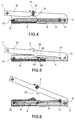
- Figure 3 shows the same device as that of the previous figures, in the same initial position, but a side view in the median plane of the device to highlight other elements of the device.
- the figure shows the slider 4 placed inside the frame 5, for example inside the tube, as well as the jack 9 placed inside the slider 4.
- the cylinder 9, integral with the articulated arm 1 by the axis of rotation 11, causes by its deployment the displacement in translation of the arm 1 relative to the frame 5.
- This translational movement of the arm in turn drives the movement in translation of the slide 4 since the latter is secured to the arm by the axis of rotation 3.
- Figure 3 also shows three axes integral with the articulated arm.
- the mechanical axis 2 located behind the ramp 8 of the frame
- This axis 2 is for example surrounded by a roller or roller 31.
- this axis 2 makes integral with the articulated arm the roller or the pebble that leads.
- This roller or roller 31 will roll on the slope due to the translational movement of the arm 1 relative to the frame 5.
- FIG. 4 shows the device, in the same view as FIG. 3, but at the moment when the roller 31 secured to the articulated arm 1 reaches the top of the slope 8 of the frame.
- the three axes of rotation 3, 11, 21 are no longer aligned.
- the axis of rotation 3 of the articulated arm 1 relative to the slider 4 is no longer aligned with the axis 20 of the jack and is then below the axis of rotation 11 of the articulated arm relative to the axis 20 of the cylinder 9.
- Figure 5 shows the device of Figure 4 at the same time by a side view.
- the lug 24 secured to the slider 4 ends its stroke in abutment against the end of the slot 23 made in the frame so that the slide stops its translational movement.
- a latch 51 blocks for example the position of the lug relative to the frame to prevent the return back of the slide which remains blocked.
- the articulated arm then finishes its translational movement and engages its rotational movement with respect to the slide around the axis 3.
- the latch 51 makes for example a rotational movement with respect to an axis 52 secured to the frame 5. It has a notch to accommodate the ergo 24. It is held in the position of the locking of the lug by a return spring.
- the lug When the lug comes to meet the latch under the effect of the translational movement of the slider, the lug imposes on the latch a rotational movement which allows the lug to continue its stroke until it reaches the latch. notch. Under the effect of the return spring, the latch then returns to its initial position and blocks the pin and thus freezes the position of the slide.
- Figure 6 illustrates the beginning of the rotation of the articulated arm 1 relative to the slide.
- the rotational movement can be engaged because the axis of rotation 11 of the articulated arm relative to the jack 9 is then above the axis of rotation 3 of the arm relative to the slide.
- Under the thrust of the cylinder which continues its course a couple is then applied to the articulated arm.
- the strong power of the cylinder compensates for the small radius of application of the torque.
- Figure 7 shows the articulated arm end of rotation, in the open state.
- the articulated arm is held in the open position by the cylinder 9.
- the jack has risen. Openings are provided in the slide and in the frame to allow passage to the cylinder.
- An object may be attached to the articulated arm, for example by means of a mechanical axis 71 which is placed at its end. It is for example possible to move this object in a translational movement followed by a rotational movement. This is for example the case to unload a mortar of a military vehicle that requires a translational movement to bring the mortar to the edge of the vehicle platform and then requires a rotational movement to the ground. Loading on the platform is done by the reverse movements.
- the cylinder is activated in the opposite direction and folds. It then drives the arm 1 in reverse rotational movements to those previously described, around the two axes 3, 11. Continuing its rotation, the arm folds on the slide and on the frame until the stop 22 s press the latch 51 to release the lug, for example the notch in which it was blocked. The slide is thus released and can engage its translation movement in the opposite direction to its initial position.
- the cylinder can be replaced by another reversible straight stroke motor auxiliary provided that it is powerful enough to drive the arm 1 in rotation. It can for example be replaced by a worm or a rack device.
- the energy source can be hydraulic or electric.
- the articulated arm has two branches, it could nevertheless include one or more than two.
- the slope 8 which makes it possible to misalign the axes of rotation could be replaced by a simple hump, or by any other protrusion that can lift the articulated arm.
- the slider 4 may be replaced by another part capable of moving in translation relative to the frame 5.
- a handling aid device provides many advantages. It makes it possible to obtain a system for loading or unloading materials using a single engine auxiliary effecting a combination of several movements. Such a system is inexpensive and does not require an automaton and sophisticated power plant. The system is simple to implement, compact and of reduced mass. It can be installed and transported on light vehicles. It is also easily transportable by air. It does not require staff with a particular technical qualification. Finally it allows a fast loading and unloading of material. It can be used for handling assistance, but more generally it can be used as an auxiliary for operations requiring a translational movement and a rotational movement.
Landscapes
- Engineering & Computer Science (AREA)
- General Engineering & Computer Science (AREA)
- Transportation (AREA)
- Mechanical Engineering (AREA)
- Manipulator (AREA)
- Jib Cranes (AREA)
- Container, Conveyance, Adherence, Positioning, Of Wafer (AREA)
- Spinning Or Twisting Of Yarns (AREA)
- Forklifts And Lifting Vehicles (AREA)
Abstract
- un bâti (5) ;
- un auxiliaire moteur à course rectiligne (9) relié au bâti par un axe de rotation (21) ;
- une pièce (4) se déplaçant en translation par rapport au bâti sur une course limitée ;
- et un bras (1) relié à la pièce par un premier axe de rotation (3) et relié à l'auxiliaire moteur par un deuxième axe de rotation (11) ;
Description
- La présente invention concerne un dispositif à bras articulé à plusieurs mouvements. Elle s'applique notamment pour la manutention d'objets selon un mouvement de translation et un mouvement de rotation.
- Les dispositifs d'aide à la manutention à bras articulé sont notamment utilisés pour le déplacement, le chargement ou le déchargement de matériels lourds ou encombrant. Il est connu de réaliser des bras articulés à plusieurs mouvements, par exemple en translation et en rotation. Ces bras sont réalisés en utilisant un auxiliaire moteur pour chaque mouvement, ce qui nécessite notamment un automate de commande et des distributeurs multivoies. Ce sont donc des systèmes relativement complexes et coûteux. A titre d'exemple, on peut citer les engins mécaniques de type pelleteuse ou grue.
La complexité de ces systèmes les rend par ailleurs peu rapide et éventuellement peu sûrs. Ils sont aussi peu simples d'utilisation et encombrants. Hors, certaines applications nécessitent une rapidité et une sûreté de manutention ainsi qu'une simplification d'utilisation des bras articulés. On peut citer comme exemple d'application le chargement et le déchargement d'un mortier d'un véhicule avec une manoeuvre la plus simple et la plus rapide possible. - Un but de l'invention est d'obtenir un bras articulé qui réponde à ces applications. Pour cela l'invention permet d'obtenir à la fois un mouvement de translation et de rotation à partir d'un seul auxiliaire moteur. A cet effet, l'invention a pour objet un dispositif à bras articulé comportant au moins :
- un bâti ;
- un auxiliaire moteur à course rectiligne relié au bâti par un axe de rotation ;
- une pièce se déplaçant en translation par rapport au bâti sur une course limitée ;
- et un bras relié à la pièce par un premier axe de rotation et relié à l'auxiliaire moteur par un deuxième axe de rotation ;
- Le bâti peut comporter une fente parallèle à la direction de translation, un ergot solidaire de la pièce en translation étant engagé dans la fente, la course de la pièce étant bloquée lorsque l'ergot atteint l'extrémité de la fente.
- De préférence, le dispositif comporte un système verrouillant la position de la pièce lorsqu'elle atteint sa fin de course en translation. Ce système de verrouillage est par exemple un verrou à ressort de rappel pivotant autour d'un axe bloquant l'ergot. Le bras comporte par exemple une protubérance s'appuyant sur le verrou lorsque le bras se replie sur la pièce 4 par un mouvement de rotation inverse.
- La protubérance sur le bâti est par exemple une rampe. L'élément solidaire mécaniquement du bras est par exemple un rouleau ou un galet venant rouler sur cette rampe.
- Dans un mode de réalisation particulier, le bras comporte par exemple au moins deux branches reliées par au moins deux axes mécaniques dont l'un traverse la pièce pour former un axe de rotation par rapport à la pièce. L'autre axe mécanique entraîne l'élément se soulevant sur la protubérance.
- La pièce en translation est par exemple un coulisseau se déplaçant dans un tube du bâti La protubérance est par exemple une pente réalisée sur le tube.
- L'auxiliaire moteur est par exemple un vérin ou une vis sans fin.
- L'invention a pour principaux avantages qu'elle permet d'obtenir un bras articulé simple à manipuler, rapide et sûr d'utilisation, peu encombrant et économique.
- D'autres caractéristiques et avantages de l'invention apparaîtront à l'aide de la description qui suit faite en regard de dessins annexés qui représentent :
- la figure 1, par une vue en perspective un exemple de réalisation d'un dispositif selon l'invention avec son bras en position initiale ;
- la figure 2, le même dispositif dans le même état par une vue de côté ;
- la figure 3, une vue de côté selon un plan médian ;
- la figure 4, le dispositif précédent avec son bras en fin de mouvement de translation et début de mouvement de rotation ;
- la figure 5, le dispositif dans le même état par une vue de côté ;
- la figure 6, le dispositif avec son bras en phase de rotation ;
- la figure 7, le dispositif avec son bras en position ouverte.
- La figure 1 présente par une vue en perspective un exemple de réalisation possible dispositif selon l'invention. Le dispositif est représenté en position fermée ou initiale. Il comporte deux branches basculantes 10 reliées par au moins deux axes mécaniques 2, 3, l'ensemble formant une structure mécanique unique 1 appelée par la suite bras articulé. Le bras articulé 1 est relié mécaniquement à un coulisseau 4 avec un degré de liberté en rotation. La rotation se fait autour d'un premier axe mécanique 3 situé à l'avant du bras. L'avant du bras indique la direction D dans laquelle le bras se déplace en translation.
Le dispositif comporte un bâti 5. Le bâti comprend par exemple un tube 6 solidaire mécaniquement de pieds 7. Le bâti peut par exemple être posé ou fixé sur une structure à l'aide de ces pieds 7. Le bâti comporte une rampe 8, réalisée par exemple sur le tube 6. En position fermée l'axe mécanique 2 est situé en arrière de la rampe, relativement au sens de déplacement selon la direction D.
Le coulisseau 4 possède un degré de liberté en translation par rapport au bâti 5. Le coulisseau se déplace ainsi par exemple en translation dans le tube 6.
Le dispositif comporte un auxiliaire moteur 9, par exemple un vérin. Par la suite, pour l'exemple de réalisation de la figure 1, l'auxiliaire moteur est un vérin. Le bras articulé 1 possède un degré de liberté par rapport au vérin 9, autour d'un deuxième axe de rotation 11. Le bras 1 est donc relié au coulisseau par le premier axe de rotation 3 et relié au vérin par le deuxième axe de rotation 11. Pour former le premier axe de rotation, l'axe 3 reliant les deux branches 10 du bras traverse par exemple le coulisseau 4. De même, le deuxième axe mécanique 11 traverse par exemple le vérin 9. II forme alors un troisième axe mécanique reliant les deux branches. Le vérin possède lui-même un degré de liberté en rotation par rapport au bâti 5. - La figure 2 présente le dispositif de la figure 1 par une vue de côté, toujours en position fermée. La figure montre donc une branche 10 du bras articulé 1 et ses deux axes de rotation 3, 11. Le bras articulé est mobile en rotation par rapport au coulisseau 4 autour du premier axe 3 et mobile par rapport au vérin 9 autour du deuxième axe 11. Le vérin 9 est quant à lui mobile par rapport au bâti 5 autour d'un axe 21 situé à l'arrière du bâti La branche 10 du bras articulé comporte un taquet 22. Le taquet est par exemple réalisé dans la même pièce mécanique que la branche 10, formé par une protubérance de cette dernière. Une fente 23 est creusée dans le bâti pour laisser dépasser vers l'extérieur un ergot 24 solidaire mécaniquement du coulisseau 4. La fente 23 est creusée sur une distance limitée parallèle à la direction de déplacement du coulisseau. La fente 23 couplée à l'ergot 24 limite la course du coulisseau. D'autres moyens pourraient être prévus pour limiter cette course.
- La figure 3 présente le même dispositif que celui des figures précédentes, dans la même position initiale, mais par une vue de côté dans le plan médian du dispositif pour mettre en évidence d'autres éléments du dispositif. En particulier, la figure montre le coulisseau 4 placé à l'intérieur du bâti 5, par exemple à l'intérieur du tube, ainsi que le vérin 9 placé à l'intérieur du coulisseau 4. Le vérin 9, solidaire du bras articulé 1 par l'axe de rotation 11, provoque par son déploiement le déplacement en translation du bras 1 par rapport au bâti 5. Ce mouvement de translation du bras entraîne à son tour le mouvement en translation du coulisseau 4 puisque ce dernier est solidaire du bras par l'axe de rotation 3.
Ces deux axes de rotations 3, 11, ainsi que l'axe de rotation 21 du vérin par rapport au bâti, sont alignés sur l'axe 20 du vérin, cet axe définissant la course du vérin. La figure 3 fait aussi apparaître trois axes solidaires du bras articulé. En plus des deux axes de rotation 3, 11, apparaît l'axe mécanique 2 situé derrière la rampe 8 du bâti Cet axe 2 est par exemple entouré d'un rouleau ou d'un galet 31. En plus de rendre solidaires les deux branches 10 du bras articulé, cet axe 2 rend solidaire du bras articulé le rouleau ou le galet qu'il entraîne. Ce rouleau ou ce galet 31 viendront rouler sur la pente par suite du mouvement de translation du bras 1 par rapport au bâti 5.
Durant la course du coulisseau dans le bâti, les trois axes de rotation 3, 11, 21 précités restent alignés tant que le rouleau 31 n'atteint pas la rampe 8 du bâti - La figure 4 montre le dispositif, dans la même vue que la figure 3, mais au moment où le rouleau 31 solidaire du bras articulé 1 arrive au sommet de la pente 8 du bâti Les trois axes de rotation 3, 11, 21 ne sont plus alignés. En particulier l'axe de rotation 3 du bras articulé 1 par rapport au coulisseau 4 n'est plus aligné avec l'axe 20 du vérin et se situe alors en dessous de l'axe de rotation 11 du bras articulé par rapport à l'axe 20 du vérin 9.
- La figure 5 montre le dispositif de la figure 4 au même instant par une vue de côté. L'ergot 24 solidaire du coulisseau 4 finit sa course en butée contre l'extrémité de la fente 23 réalisée dans le bâti de sorte que le coulisseau arrête son mouvement de translation. Un verrou 51 bloque par exemple la position de l'ergot par rapport au bâti pour empêcher le retour en arrière du coulisseau qui reste bloqué. Le bras articulé finit alors son mouvement de translation et engage son mouvement de rotation par rapport au coulisseau autour de l'axe 3. Le verrou 51 fait par exemple un mouvement de rotation par rapport à un axe 52 solidaire du bâti 5. Il possède une encoche pour accueillir l'ergo 24. Il est maintenu en position du blocage de l'ergot par un ressort de rappel. Lorsque l'ergot arrive à la rencontre du verrou sous l'effet du mouvement de translation du coulisseau, l'ergot impose au verrou un mouvement de rotation qui permet à l'ergot de continuer sa course jusqu'à ce qu'il atteigne l'encoche. Sous l'effet du ressort de rappel, le verrou revient alors à sa position initiale et bloque l'ergot et donc fige la position du coulisseau.
- La figure 6 illustre le début de la rotation du bras articulé 1 par rapport au coulisseau. Le mouvement de rotation peut être engagé du fait que l'axe de rotation 11 du bras articulé par rapport au vérin 9 est alors au-dessus de l'axe de rotation 3 du bras par rapport au coulisseau. Sous la poussée du vérin qui continue sa course un couple est alors appliqué sur le bras articulé. La forte puissance du vérin compense le faible rayon d'application du couple.
- Dans ce mouvement de rotation le vérin se soulève par un léger mouvement de rotation par rapport au bâti 5 autour de l'axe 21 situé à l'arrière de ce dernier. De son côté le bras articulé 1 continue son mouvement de rotation autour de l'axe 3 solidaire du coulisseau, combiné à un autre mouvement de rotation autour de l'axe 11 solidaire du vérin 9 en rotation.
- La figure 7 présente le bras articulé en fin de rotation, à l'état ouvert. Le bras articulé est maintenu en position ouverte par le vérin 9. Par suite de son mouvement de rotation autour de l'axe 21 solidaire du bâti 5, le vérin s'est soulevé. Des ouvertures son prévues dans le coulisseau et dans le bâti pour laisser un passage au vérin. Un objet peut être accroché au bras articulé, par exemple par l'intermédiaire d'un axe mécanique 71 qui placé à son extrémité. Il est par exemple ainsi possible de déplacer cet objet selon un mouvement de translation suivi d'un mouvement de rotation. C'est par exemple le cas pour décharger un mortier d'un véhicule militaire qui nécessite un mouvement de translation pour amener le mortier au bord de la plate-forme du véhicule puis qui nécessite ensuite un mouvement de rotation pour le poser au sol. Le chargement sur la plate-forme se fait par les mouvements inverses.
Pour fermer le bras articulé, c'est à dire pour le ramener en position initiale, le vérin est activé en sens inverse et se replie. Il entraîne alors le bras 1 dans des mouvements de rotation inverses à ceux précédemment décrits, autour des deux axes 3, 11. En continuant sa rotation, le bras se replie sur le coulisseau et sur le bâti jusqu'à ce que le taquet 22 s'appuie sur le verrou 51 pour libérer l'ergot, par exemple de l'encoche dans laquelle il était bloqué. Le coulisseau est ainsi libéré et peut engager son mouvement de translation en sens inverse vers sa position initiale. - Le vérin peut être remplacé par un autre auxiliaire moteur à course rectiligne réversible pourvu qu'il soit assez puissant pour entraîner le bras 1 en rotation. II peut par exemple être remplacé par une vis sans fin ou un dispositif à crémaillère. La source d'énergie peut être hydraulique ou électrique. Dans l'exemple de réalisation présenté par les figures le bras articulé comporte deux branches, il pourrait néanmoins en comporter une seule ou plus de deux. La pente 8 qui permet de désaligner les axes de rotation pourrait être remplacée par une simple bosse, ou par toute autre protubérance qui permet de soulever le bras articulé. Le coulisseau 4 peut être remplacé par une autre pièce capable de se déplacer en translation par rapport au bâti 5.
- Un dispositif d'aide à la manutention selon l'invention apporte de nombreux avantages. Il permet d'obtenir un système de chargement ou de déchargement de matériels à l'aide d'un seul auxiliaire moteur réalisant une combinaison de plusieurs mouvements. Un tel système est peu coûteux et ne nécessite pas d'automate et d'installation motrice sophistiquée. Le système est simple à mettre en oeuvre, peu encombrant et de masse réduite. Il peut être installé et transporté sur des véhicules légers. Il est aussi facilement transportable par moyens aériens. Il ne requiert pas de personnel ayant une qualification technique particulière. Enfin il autorise un chargement et un déchargement rapide de matériel. II peut être utilisé pour l'aide à la manutention, mais plus généralement il peut être utilisé comme auxiliaire pour des opérations nécessitant un mouvement de translation et un mouvement de rotation.
Claims (16)
- Dispositif à bras articulé, caractérisé en ce qu'il comporte au moins :- un bâti (5) ;- un auxiliaire moteur à course rectiligne (9) relié au bâti par un axe de rotation (21) ;- une pièce (4) se déplaçant en translation par rapport au bâti sur une course limitée ;- et un bras (1) relié à la pièce par un premier axe de rotation (3) et relié à l'auxiliaire moteur par un deuxième axe de rotation (11) ;l'auxiliaire moteur entraînant la pièce (4) en translation qui entraîne elle-même le bras (1) en translation par rapport au bâti (5), le bâti comportant une protubérance (8) sur lequel vient se soulever un élément (31) solidaire mécaniquement du bras (1) provoquant le désalignement du deuxième axe de rotation (11) du bras par rapport à son premier axe de rotation (3), la poussée de l'auxiliaire moteur produisant alors un couple d'entraînement du bras en rotation.
- Dispositif selon l'une quelconque des revendications précédentes, caractérisé en ce que le bâti comporte une fente (23) parallèle à la direction de translation, un ergot (24) solidaire de la pièce (4) en translation étant engagé dans la fente, la course de la pièce (4) étant bloquée lorsque l'ergot atteint l'extrémité de la fente.
- Dispositif selon l'une quelconque des revendications précédentes, caractérisé en ce qu'il comporte un système (51, 52) verrouillant la position de la pièce (4) lorsqu'elle atteint sa fin de course en translation.
- Dispositif selon les revendications 2 et 3, caractérisé en ce que le système de verrouillage est un verrou (51) à ressort de rappel pivotant autour d'un axe (52) bloquant l'ergot (24).
- Dispositif selon la revendication 4, caractérisé en ce que le bras (1) comporte une protubérance (22) s'appuyant sur le verrou (51) lorsque le bras se replie sur la pièce (4) par un mouvement de rotation inverse.
- Dispositif selon l'une quelconque des revendications précédentes, caractérisé en ce que la protubérance (8) est une rampe.
- Dispositif selon l'une quelconque des revendications précédentes, caractérisé en ce que l'élément (31) solidaire mécaniquement du bras est un rouleau.
- Dispositif selon l'une quelconque des revendications 1 à 6, caractérisé en ce que l'élément (31) solidaire mécaniquement du bras est un galet.
- Dispositif selon l'une quelconque des revendications précédentes, caractérisé en ce que le bras (1) comporte au moins deux branches (10) reliées par au moins deux axes mécaniques (2, 3) dont l'un (3) traverse la pièce (4) pour former un axe de rotation par rapport à la pièce (4).
- Dispositif selon la revendication 9, caractérisé en ce que l'autre axe mécanique (2) entraîne l'élément (31) se soulevant sur la protubérance (8).
- Dispositif selon l'une quelconque des revendications précédentes, caractérisé en ce que la pièce (4) est un coulisseau se déplaçant dans un tube (6) du bâti
- Dispositif selon la revendication 11, caractérisé en ce que la protubérance (8) est une pente réalisée sur le tube (6).
- Dispositif selon l'une quelconque des revendications précédentes, caractérisé en ce que l'auxiliaire moteur (9) est un vérin.
- Dispositif selon l'une quelconque des revendications précédentes, caractérisé en ce que l'auxiliaire moteur (9) est une vis sans fin.
- Dispositif selon l'une quelconque des revendications 1 à 13, caractérisé en ce que l'auxiliaire moteur (9) est un dispositif à crémaillère.
- Dispositif selon l'une quelconque des revendications précédentes, caractérisé en ce qu'il est utilisé pour l'aide à la manutention.
Applications Claiming Priority (1)
| Application Number | Priority Date | Filing Date | Title |
|---|---|---|---|
| FR0408192A FR2873318B1 (fr) | 2004-07-23 | 2004-07-23 | Dispositif de bras articule a plusieurs mouvements notamment pour l'aide a la manutention |
Publications (2)
| Publication Number | Publication Date |
|---|---|
| EP1619073A1 true EP1619073A1 (fr) | 2006-01-25 |
| EP1619073B1 EP1619073B1 (fr) | 2008-08-27 |
Family
ID=34947710
Family Applications (1)
| Application Number | Title | Priority Date | Filing Date |
|---|---|---|---|
| EP05106769A Expired - Lifetime EP1619073B1 (fr) | 2004-07-23 | 2005-07-22 | Dispositif de bras articulé à plusieurs mouvements notamment pour l'aide à la manutention |
Country Status (4)
| Country | Link |
|---|---|
| EP (1) | EP1619073B1 (fr) |
| AT (1) | ATE406284T1 (fr) |
| DE (1) | DE602005009291D1 (fr) |
| FR (1) | FR2873318B1 (fr) |
Citations (3)
| Publication number | Priority date | Publication date | Assignee | Title |
|---|---|---|---|---|
| DE1100482B (de) * | 1958-03-03 | 1961-02-23 | Alfred Kleinknecht | Fahrzeug, insbesondere Lastkraftwagen, mit einer kippbaren Ladebruecke |
| US3630571A (en) * | 1967-08-07 | 1971-12-28 | David G Saldana | Auxiliary dumping apparatus for a vehicle |
| US4943118A (en) * | 1989-03-07 | 1990-07-24 | Louis Davis | End dumping trailer |
-
2004
- 2004-07-23 FR FR0408192A patent/FR2873318B1/fr not_active Expired - Fee Related
-
2005
- 2005-07-22 EP EP05106769A patent/EP1619073B1/fr not_active Expired - Lifetime
- 2005-07-22 DE DE602005009291T patent/DE602005009291D1/de not_active Expired - Lifetime
- 2005-07-22 AT AT05106769T patent/ATE406284T1/de active
Patent Citations (3)
| Publication number | Priority date | Publication date | Assignee | Title |
|---|---|---|---|---|
| DE1100482B (de) * | 1958-03-03 | 1961-02-23 | Alfred Kleinknecht | Fahrzeug, insbesondere Lastkraftwagen, mit einer kippbaren Ladebruecke |
| US3630571A (en) * | 1967-08-07 | 1971-12-28 | David G Saldana | Auxiliary dumping apparatus for a vehicle |
| US4943118A (en) * | 1989-03-07 | 1990-07-24 | Louis Davis | End dumping trailer |
Also Published As
| Publication number | Publication date |
|---|---|
| FR2873318B1 (fr) | 2006-09-29 |
| DE602005009291D1 (de) | 2008-10-09 |
| EP1619073B1 (fr) | 2008-08-27 |
| ATE406284T1 (de) | 2008-09-15 |
| FR2873318A1 (fr) | 2006-01-27 |
Similar Documents
| Publication | Publication Date | Title |
|---|---|---|
| EP2073228B1 (fr) | Commande compacte pour appareillage électrique moyennes et hautes tensions | |
| EP2089302B1 (fr) | Sabot de calage d'une roue et installation de calage motorisee | |
| EP2602804B1 (fr) | Dispositif de commande des pôles dans un appareil de commande électrique moyenne tension | |
| FR2775717A1 (fr) | Dispositif d'ouverture/fermeture d'un ouvrant, notamment pour vehicule automobile | |
| EP0216710A1 (fr) | Dispositif de bridage à têtes multiples à commande unique à distance | |
| EP2930130B1 (fr) | Dispositif de cale d'immobilisation de vehicule | |
| CA3046506C (fr) | Procede de manoeuvre de portes de soute d'atterrisseur d'aeronef | |
| EP1619073B1 (fr) | Dispositif de bras articulé à plusieurs mouvements notamment pour l'aide à la manutention | |
| CA3149948C (fr) | Nacelle, notamment nacelle elevatrice | |
| FR2656858A1 (fr) | Structure unitaire deplacable de calage ou de soutien d'un vehicule routier par ses roues. | |
| EP1655445A2 (fr) | Commande d'un système d'aération à volets pivotants avec ouverture d'urgence | |
| FR2946684A1 (fr) | Ensemble de porte de garage. | |
| EP1378621B1 (fr) | Mécanisme d'embrayage pour la commande d'une serrure, et porte le comportant | |
| WO2006131608A1 (fr) | Dispositif de deplacement de vehicules | |
| EP4035745B1 (fr) | Dispositif de manoeuvre d'un panneau obturateur a mecanisme de butee debrayable | |
| WO2003010028A1 (fr) | Procede de commande de rambardes laterales d'un elevateur d'un vehicule et dispositif le mettant en oeuvre | |
| FR2533871A1 (en) | Device applicable chiefly to vehicles in order to obtain an anti-rollback effect | |
| EP1992320B1 (fr) | Meuble déplaçable à roue motrice et directrice | |
| EP2073227B1 (fr) | Commande compacte et robuste pour appareillage electrique moyennes et hautes tensions | |
| FR2695971A1 (fr) | Groupe de freinage avec déblocage de secours pour moteurs électriques. | |
| FR2589190A1 (fr) | Dispositif de commande motorisee pour l'ouverture et la fermeture d'un portail | |
| FR2742467A1 (fr) | Commande exterieure universelle de porte notamment pour vehicule automobile | |
| FR2839051A1 (fr) | Dispositif de distribution de palettes | |
| FR2594165A1 (fr) | Dispositif de verrouillage de securite d'une porte coulissante avec loquet basculant rappele elastiquement en position de fermeture. | |
| CA2931298A1 (fr) | Structure segmentee, en particulier pour reflecteur d'antenne de satellite |
Legal Events
| Date | Code | Title | Description |
|---|---|---|---|
| PUAI | Public reference made under article 153(3) epc to a published international application that has entered the european phase |
Free format text: ORIGINAL CODE: 0009012 |
|
| AK | Designated contracting states |
Kind code of ref document: A1 Designated state(s): AT BE BG CH CY CZ DE DK EE ES FI FR GB GR HU IE IS IT LI LT LU LV MC NL PL PT RO SE SI SK TR |
|
| AX | Request for extension of the european patent |
Extension state: AL BA HR MK YU |
|
| 17P | Request for examination filed |
Effective date: 20060725 |
|
| AKX | Designation fees paid |
Designated state(s): AT BE BG CH CY CZ DE DK EE ES FI FR GB GR HU IE IS IT LI LT LU LV MC NL PL PT RO SE SI SK TR |
|
| GRAP | Despatch of communication of intention to grant a patent |
Free format text: ORIGINAL CODE: EPIDOSNIGR1 |
|
| GRAS | Grant fee paid |
Free format text: ORIGINAL CODE: EPIDOSNIGR3 |
|
| GRAA | (expected) grant |
Free format text: ORIGINAL CODE: 0009210 |
|
| AK | Designated contracting states |
Kind code of ref document: B1 Designated state(s): AT BE BG CH CY CZ DE DK EE ES FI FR GB GR HU IE IS IT LI LT LU LV MC NL PL PT RO SE SI SK TR |
|
| REG | Reference to a national code |
Ref country code: GB Ref legal event code: FG4D Free format text: NOT ENGLISH |
|
| REG | Reference to a national code |
Ref country code: CH Ref legal event code: EP |
|
| REG | Reference to a national code |
Ref country code: IE Ref legal event code: FG4D Free format text: LANGUAGE OF EP DOCUMENT: FRENCH |
|
| REF | Corresponds to: |
Ref document number: 602005009291 Country of ref document: DE Date of ref document: 20081009 Kind code of ref document: P |
|
| REG | Reference to a national code |
Ref country code: SE Ref legal event code: TRGR |
|
| PG25 | Lapsed in a contracting state [announced via postgrant information from national office to epo] |
Ref country code: NL Free format text: LAPSE BECAUSE OF FAILURE TO SUBMIT A TRANSLATION OF THE DESCRIPTION OR TO PAY THE FEE WITHIN THE PRESCRIBED TIME-LIMIT Effective date: 20080827 Ref country code: LT Free format text: LAPSE BECAUSE OF FAILURE TO SUBMIT A TRANSLATION OF THE DESCRIPTION OR TO PAY THE FEE WITHIN THE PRESCRIBED TIME-LIMIT Effective date: 20080827 Ref country code: IS Free format text: LAPSE BECAUSE OF FAILURE TO SUBMIT A TRANSLATION OF THE DESCRIPTION OR TO PAY THE FEE WITHIN THE PRESCRIBED TIME-LIMIT Effective date: 20081227 |
|
| PG25 | Lapsed in a contracting state [announced via postgrant information from national office to epo] |
Ref country code: FI Free format text: LAPSE BECAUSE OF FAILURE TO SUBMIT A TRANSLATION OF THE DESCRIPTION OR TO PAY THE FEE WITHIN THE PRESCRIBED TIME-LIMIT Effective date: 20080827 Ref country code: ES Free format text: LAPSE BECAUSE OF FAILURE TO SUBMIT A TRANSLATION OF THE DESCRIPTION OR TO PAY THE FEE WITHIN THE PRESCRIBED TIME-LIMIT Effective date: 20081208 Ref country code: SI Free format text: LAPSE BECAUSE OF FAILURE TO SUBMIT A TRANSLATION OF THE DESCRIPTION OR TO PAY THE FEE WITHIN THE PRESCRIBED TIME-LIMIT Effective date: 20080827 Ref country code: LV Free format text: LAPSE BECAUSE OF FAILURE TO SUBMIT A TRANSLATION OF THE DESCRIPTION OR TO PAY THE FEE WITHIN THE PRESCRIBED TIME-LIMIT Effective date: 20080827 |
|
| REG | Reference to a national code |
Ref country code: IE Ref legal event code: FD4D |
|
| PG25 | Lapsed in a contracting state [announced via postgrant information from national office to epo] |
Ref country code: BG Free format text: LAPSE BECAUSE OF FAILURE TO SUBMIT A TRANSLATION OF THE DESCRIPTION OR TO PAY THE FEE WITHIN THE PRESCRIBED TIME-LIMIT Effective date: 20081127 Ref country code: DK Free format text: LAPSE BECAUSE OF FAILURE TO SUBMIT A TRANSLATION OF THE DESCRIPTION OR TO PAY THE FEE WITHIN THE PRESCRIBED TIME-LIMIT Effective date: 20080827 Ref country code: IE Free format text: LAPSE BECAUSE OF FAILURE TO SUBMIT A TRANSLATION OF THE DESCRIPTION OR TO PAY THE FEE WITHIN THE PRESCRIBED TIME-LIMIT Effective date: 20080827 |
|
| PG25 | Lapsed in a contracting state [announced via postgrant information from national office to epo] |
Ref country code: CZ Free format text: LAPSE BECAUSE OF FAILURE TO SUBMIT A TRANSLATION OF THE DESCRIPTION OR TO PAY THE FEE WITHIN THE PRESCRIBED TIME-LIMIT Effective date: 20080827 Ref country code: PT Free format text: LAPSE BECAUSE OF FAILURE TO SUBMIT A TRANSLATION OF THE DESCRIPTION OR TO PAY THE FEE WITHIN THE PRESCRIBED TIME-LIMIT Effective date: 20090127 Ref country code: SK Free format text: LAPSE BECAUSE OF FAILURE TO SUBMIT A TRANSLATION OF THE DESCRIPTION OR TO PAY THE FEE WITHIN THE PRESCRIBED TIME-LIMIT Effective date: 20080827 Ref country code: RO Free format text: LAPSE BECAUSE OF FAILURE TO SUBMIT A TRANSLATION OF THE DESCRIPTION OR TO PAY THE FEE WITHIN THE PRESCRIBED TIME-LIMIT Effective date: 20080827 |
|
| PLBE | No opposition filed within time limit |
Free format text: ORIGINAL CODE: 0009261 |
|
| STAA | Information on the status of an ep patent application or granted ep patent |
Free format text: STATUS: NO OPPOSITION FILED WITHIN TIME LIMIT |
|
| PG25 | Lapsed in a contracting state [announced via postgrant information from national office to epo] |
Ref country code: EE Free format text: LAPSE BECAUSE OF FAILURE TO SUBMIT A TRANSLATION OF THE DESCRIPTION OR TO PAY THE FEE WITHIN THE PRESCRIBED TIME-LIMIT Effective date: 20080827 |
|
| PGFP | Annual fee paid to national office [announced via postgrant information from national office to epo] |
Ref country code: MC Payment date: 20090629 Year of fee payment: 5 |
|
| 26N | No opposition filed |
Effective date: 20090528 |
|
| PG25 | Lapsed in a contracting state [announced via postgrant information from national office to epo] |
Ref country code: PL Free format text: LAPSE BECAUSE OF FAILURE TO SUBMIT A TRANSLATION OF THE DESCRIPTION OR TO PAY THE FEE WITHIN THE PRESCRIBED TIME-LIMIT Effective date: 20080827 |
|
| PG25 | Lapsed in a contracting state [announced via postgrant information from national office to epo] |
Ref country code: GR Free format text: LAPSE BECAUSE OF FAILURE TO SUBMIT A TRANSLATION OF THE DESCRIPTION OR TO PAY THE FEE WITHIN THE PRESCRIBED TIME-LIMIT Effective date: 20081128 |
|
| PG25 | Lapsed in a contracting state [announced via postgrant information from national office to epo] |
Ref country code: MC Free format text: LAPSE BECAUSE OF NON-PAYMENT OF DUE FEES Effective date: 20100731 |
|
| PG25 | Lapsed in a contracting state [announced via postgrant information from national office to epo] |
Ref country code: LU Free format text: LAPSE BECAUSE OF NON-PAYMENT OF DUE FEES Effective date: 20090722 |
|
| PG25 | Lapsed in a contracting state [announced via postgrant information from national office to epo] |
Ref country code: HU Free format text: LAPSE BECAUSE OF FAILURE TO SUBMIT A TRANSLATION OF THE DESCRIPTION OR TO PAY THE FEE WITHIN THE PRESCRIBED TIME-LIMIT Effective date: 20090228 |
|
| PG25 | Lapsed in a contracting state [announced via postgrant information from national office to epo] |
Ref country code: CY Free format text: LAPSE BECAUSE OF FAILURE TO SUBMIT A TRANSLATION OF THE DESCRIPTION OR TO PAY THE FEE WITHIN THE PRESCRIBED TIME-LIMIT Effective date: 20080827 |
|
| PGFP | Annual fee paid to national office [announced via postgrant information from national office to epo] |
Ref country code: TR Payment date: 20130621 Year of fee payment: 9 |
|
| PGFP | Annual fee paid to national office [announced via postgrant information from national office to epo] |
Ref country code: SE Payment date: 20130711 Year of fee payment: 9 Ref country code: BE Payment date: 20130712 Year of fee payment: 9 Ref country code: DE Payment date: 20130717 Year of fee payment: 9 Ref country code: CH Payment date: 20130712 Year of fee payment: 9 Ref country code: AT Payment date: 20130626 Year of fee payment: 9 |
|
| PGFP | Annual fee paid to national office [announced via postgrant information from national office to epo] |
Ref country code: GB Payment date: 20130717 Year of fee payment: 9 Ref country code: FR Payment date: 20130724 Year of fee payment: 9 |
|
| PGFP | Annual fee paid to national office [announced via postgrant information from national office to epo] |
Ref country code: IT Payment date: 20130716 Year of fee payment: 9 |
|
| REG | Reference to a national code |
Ref country code: DE Ref legal event code: R119 Ref document number: 602005009291 Country of ref document: DE |
|
| REG | Reference to a national code |
Ref country code: CH Ref legal event code: PL |
|
| REG | Reference to a national code |
Ref country code: SE Ref legal event code: EUG |
|
| REG | Reference to a national code |
Ref country code: AT Ref legal event code: MM01 Ref document number: 406284 Country of ref document: AT Kind code of ref document: T Effective date: 20140722 |
|
| GBPC | Gb: european patent ceased through non-payment of renewal fee |
Effective date: 20140722 |
|
| REG | Reference to a national code |
Ref country code: FR Ref legal event code: ST Effective date: 20150331 |
|
| PG25 | Lapsed in a contracting state [announced via postgrant information from national office to epo] |
Ref country code: DE Free format text: LAPSE BECAUSE OF NON-PAYMENT OF DUE FEES Effective date: 20150203 Ref country code: CH Free format text: LAPSE BECAUSE OF NON-PAYMENT OF DUE FEES Effective date: 20140731 Ref country code: IT Free format text: LAPSE BECAUSE OF NON-PAYMENT OF DUE FEES Effective date: 20140722 Ref country code: LI Free format text: LAPSE BECAUSE OF NON-PAYMENT OF DUE FEES Effective date: 20140731 |
|
| REG | Reference to a national code |
Ref country code: DE Ref legal event code: R119 Ref document number: 602005009291 Country of ref document: DE Effective date: 20150203 |
|
| PG25 | Lapsed in a contracting state [announced via postgrant information from national office to epo] |
Ref country code: GB Free format text: LAPSE BECAUSE OF NON-PAYMENT OF DUE FEES Effective date: 20140722 Ref country code: AT Free format text: LAPSE BECAUSE OF NON-PAYMENT OF DUE FEES Effective date: 20140722 Ref country code: FR Free format text: LAPSE BECAUSE OF NON-PAYMENT OF DUE FEES Effective date: 20140731 Ref country code: SE Free format text: LAPSE BECAUSE OF NON-PAYMENT OF DUE FEES Effective date: 20140723 |
|
| PG25 | Lapsed in a contracting state [announced via postgrant information from national office to epo] |
Ref country code: BE Free format text: LAPSE BECAUSE OF NON-PAYMENT OF DUE FEES Effective date: 20140731 |
|
| PG25 | Lapsed in a contracting state [announced via postgrant information from national office to epo] |
Ref country code: TR Free format text: LAPSE BECAUSE OF NON-PAYMENT OF DUE FEES Effective date: 20140722 |