EP1619019A1 - Versteifungskörper - Google Patents
Versteifungskörper Download PDFInfo
- Publication number
- EP1619019A1 EP1619019A1 EP04405469A EP04405469A EP1619019A1 EP 1619019 A1 EP1619019 A1 EP 1619019A1 EP 04405469 A EP04405469 A EP 04405469A EP 04405469 A EP04405469 A EP 04405469A EP 1619019 A1 EP1619019 A1 EP 1619019A1
- Authority
- EP
- European Patent Office
- Prior art keywords
- creped
- stiffening
- material layer
- layer
- body according
- Prior art date
- Legal status (The legal status is an assumption and is not a legal conclusion. Google has not performed a legal analysis and makes no representation as to the accuracy of the status listed.)
- Granted
Links
Images
Classifications
-
- B—PERFORMING OPERATIONS; TRANSPORTING
- B32—LAYERED PRODUCTS
- B32B—LAYERED PRODUCTS, i.e. PRODUCTS BUILT-UP OF STRATA OF FLAT OR NON-FLAT, e.g. CELLULAR OR HONEYCOMB, FORM
- B32B29/00—Layered products comprising a layer of paper or cardboard
- B32B29/08—Corrugated paper or cardboard
-
- B—PERFORMING OPERATIONS; TRANSPORTING
- B32—LAYERED PRODUCTS
- B32B—LAYERED PRODUCTS, i.e. PRODUCTS BUILT-UP OF STRATA OF FLAT OR NON-FLAT, e.g. CELLULAR OR HONEYCOMB, FORM
- B32B5/00—Layered products characterised by the non- homogeneity or physical structure, i.e. comprising a fibrous, filamentary, particulate or foam layer; Layered products characterised by having a layer differing constitutionally or physically in different parts
- B32B5/18—Layered products characterised by the non- homogeneity or physical structure, i.e. comprising a fibrous, filamentary, particulate or foam layer; Layered products characterised by having a layer differing constitutionally or physically in different parts characterised by features of a layer of foamed material
-
- B—PERFORMING OPERATIONS; TRANSPORTING
- B60—VEHICLES IN GENERAL
- B60R—VEHICLES, VEHICLE FITTINGS, OR VEHICLE PARTS, NOT OTHERWISE PROVIDED FOR
- B60R13/00—Elements for body-finishing, identifying, or decorating; Arrangements or adaptations for advertising purposes
- B60R13/02—Internal Trim mouldings ; Internal Ledges; Wall liners for passenger compartments; Roof liners
- B60R13/0206—Arrangements of fasteners and clips specially adapted for attaching inner vehicle liners or mouldings
-
- B—PERFORMING OPERATIONS; TRANSPORTING
- B60—VEHICLES IN GENERAL
- B60R—VEHICLES, VEHICLE FITTINGS, OR VEHICLE PARTS, NOT OTHERWISE PROVIDED FOR
- B60R13/00—Elements for body-finishing, identifying, or decorating; Arrangements or adaptations for advertising purposes
- B60R13/02—Internal Trim mouldings ; Internal Ledges; Wall liners for passenger compartments; Roof liners
- B60R13/0212—Roof or head liners
-
- B—PERFORMING OPERATIONS; TRANSPORTING
- B60—VEHICLES IN GENERAL
- B60R—VEHICLES, VEHICLE FITTINGS, OR VEHICLE PARTS, NOT OTHERWISE PROVIDED FOR
- B60R13/00—Elements for body-finishing, identifying, or decorating; Arrangements or adaptations for advertising purposes
- B60R13/08—Insulating elements, e.g. for sound insulation
- B60R13/0815—Acoustic or thermal insulation of passenger compartments
Definitions
- the invention relates to a stiffening body with a flexible lightweight panel having at least one cover layer connected to a surface of the panel.
- the roof outer skin is stiffened from the vehicle interior ago.
- sound insulation and thermal insulation are achieved with the roof reinforcement glued over adhesive beads or an adhesive applied over the entire surface with the roof cladding.
- a known from EP-B-0 825 066 roof stiffening for vehicles consists of a one-sided connected to a cover layer of foamed plastic plate.
- a sheet of foamed plastic connected on both sides to a cover layer is first produced.
- the foamed plate is split in the middle in two unilaterally provided with a top layer plates and cut to size on the dimensions of the roof skin.
- a single cover layer is also tailored to the dimension of the roof skin with excess and formed and glued together with an adhesive layer between the foam plate and the individual cover layer in a shape corresponding to the curvature and contour of the roof skin on the final shape and glued.
- the molding is punched out for matching roof stiffening.
- the foamed plastic is a polyurethane foam, the outer layers are made of kraftliner. The expensive molds required to produce the roof reinforcement result in correspondingly high final costs.
- a plate made of foamed plastic is provided with cover layers arranged on both sides and this then by central splitting in two on one side with a cover layer cut foam sheets cut.
- the final shape of the plate for roof stiffening is done here by direct bonding of the uncoated side of the plate with the roof skin.
- the invention has for its object to provide a stiffening body of the type mentioned, which has the same dimensions compared to conventional stiffening bodies increased bending strength.
- the cover layer (s) comprises / comprise at least one layer of material having a multiplicity of stiffening elements formed by the material layer and rising from the plate surface.
- the material layer is preferably creped to form the stiffening elements. That is, the stiffening elements are produced when creping the material layer.
- the invention takes advantage of the fact that creping, due to the increase in the thickness of the creped material occurring at right angles to the creping, increases the transverse rigidity of the base material and thus leads to a better flexural strength of the stiffening body.
- both cover layers need to comprise a creped layer of material, but one cover layer may be creped and the other cover layer may be in a smooth or planar configuration.
- the creped material layer is preferably a crepe paper, a creped plastic or metal foil or a creped multilayer film with individual ones Layers of one or more paper layers, plastic films and / or metal foils.
- metal foil in particular, an aluminum foil is suitable.
- the flexible lightweight panel preferably consists of foamed plastic, in particular of a polyurethane foam, preferably of a closed-cell polyurethane foam having a density of about 30 to 55 g / m 3 .
- a preferred creped material layer consists of a crepe paper layer, which may be uncoated or also coated on one or both sides with a plastic film of, for example, polyethylene, polypropylene or polyethylene terephthalate as a water vapor barrier.
- a plastic film of, for example, polyethylene, polypropylene or polyethylene terephthalate as a water vapor barrier.
- the crepe paper layer can also be impregnated with water-repellent, flame-retardant and / or mold and rot-preventing substances.
- stiffening bodies according to the invention can advantageously be used wherever the outer skin of a component is to be protected from denting which occurs due to external forces.
- a preferred area of application are roof stiffeners for vehicles, with headliners, if appropriate combined with the roof skin reinforcement, being able to be equipped with the reinforcing bodies.
- Further applications of the stiffening body according to the invention are the stiffening of flat planks and moldings of sheet metal or plastic of all kinds, such as e.g. Bonnets, refrigerator doors and other components to be reinforced against being pressed in.
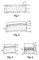
- a roof stiffener 10 according to Fig. 1 consists of a plate 12 made of foamed plastic, e.g. Polyurethane foam with cover layers 14, 16 on both sides of a creped material layer, e.g. Crepe paper.
- the total thickness D of the roof stiffener 10 is for example about 5 to 10 mm.
- this sandwich material usually takes place in the form of strip material in a double-belt press, in which, at the same time as the foaming of the plastic to the foamed strip material, a firm connection with the cover layers fed in strip form is produced.
- the individual roof stiffeners are cut to length from the strip material and punched into a shaped part adapted to the roof skin.
- the roof stiffener 10 is bonded by means of a crawler or full surface applied adhesive 18 with a roof 20 of a vehicle not shown in the drawing.
- the variant of a roof reinforcement 10 shown in FIG. 3 consists of a foam plate 12 connected only on one side to a cover layer 16, which is glued to its uncoated side via an adhesive layer 18 to the roof skin.
- the preparation of this variant is carried out in the manner described above in a double-belt press, which provided on both sides with cover layers 14, 16 join foamed strip material in the middle split into two parts provided with a cover layer on one side.
- Grooves or grooves introduced during the punching process can additionally have a stiffening effect in the transverse direction and also produce a longitudinally acting deformation stiffness.
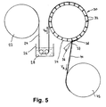
- a plant shown in Fig. 5 for producing a creped film strip 40 comprises a first winding roll 22 with the uncreped film strip 24, a bath 26 with liquid lubricant 28 for wetting the film strip 24, a cylindrical vacuum drum 30 having a plurality of on the lateral surface 34 of Vacuum drum 30 ending suction openings 32, a doctor blade 36, the blade tip 37 extends substantially to the lateral surface 34 and extends over the entire width of the vacuum drum 30, and a second winding roll 42 for winding the creped film strip 40th
- the uncreped foil strip 24 for example an aluminum foil
- the first winding roll 22 is unwound from the first winding roll 22 and subsequently guided through the bath 26 with the liquid lubricant 28, for example water.
- the wetted with the liquid lubricant 28 film strip 24 is then brought to the vacuum drum 30 and is the lateral surface thereof 34 on.
- the vacuum drum 30 is connected to a vacuum source, not shown in the drawing, for example a vacuum pump, so that there is a negative pressure in the interior of the drum with respect to the outside atmosphere.
- a vacuum source not shown in the drawing, for example a vacuum pump
- the foil strip 24 wetted with the lubricant 28 accumulates and is creped uniformly.
- the creped film strip 40 is withdrawn at the doctor blade 36 from the lateral surface 34 of the vacuum drum 30 and wound on the second winding roller 42.
- the degree of creping of the creped film web 40 is controlled by the rotational speeds of the vacuum drum 30 and the second winding roll 42.
- the winding roll 42 serves here simultaneously as a take-off device for the creped film strip 40.
- the rotational speeds of the vacuum drum 30 and the second winding roll 42 are adjusted so that the take-off speed V A , with the creped film strip 40 is subtracted from the lateral surface 34 of the vacuum drum 30, is smaller than that of the cladding velocity V M corresponding running speed of the uncreped foil strip 24.
- the denser is the creping of the foil strip 24 in the storage area 38 in front of the doctor blade 36, which corresponds to a correspondingly higher level of creping.
- the creped foil strip 42 wound up on the second winding roll can be used directly as a cover layer 14, 16 for producing a stiffening body 10 with a flexible lightweight plate 12, as used for example for the roof stiffener 10 described above.
- the vacuum drum 30 is heated so that the plastic film or the plastic film reaches the required to carry out the crepe softening point.
Landscapes
- Engineering & Computer Science (AREA)
- Mechanical Engineering (AREA)
- Physics & Mathematics (AREA)
- Acoustics & Sound (AREA)
- Laminated Bodies (AREA)
Abstract
Description
- Die Erfindung betrifft einen Versteifungskörper mit einer biegsamen Leichtstoffplatte mit wenigstens einer mit einer Oberfläche der Platte verbundenen Deckschicht.
- Zur Erhöhung der Belastbarkeit der Dachfläche eines Fahrzeugs wird die Dachaussenhaut vom Fahrzeuginnern her versteift. Mit der über Klebstoffraupen oder einen vollflächig aufgetragenen Klebstoff mit der Dachhaut verklebten Dachversteifung wird gleichzeitig eine Schalldämmung und Wärmeisolierung erreicht.
- Eine aus der EP-B-O 825 066 bekannte Dachversteifung für Fahrzeuge besteht aus einer einseitig mit einer Deckschicht verbundenen Platte aus geschäumtem Kunststoff. Zur Herstellung dieser Dachversteifung wird zunächst eine beidseitig mit einer Deckschicht verbundene Platte aus geschäumtem Kunststoff hergestellt. Anschliessend wird die geschäumte Platte mittig in zwei einseitig mit einer Deckschicht versehene Platten gespalten und mit Übermass auf die Abmessungen der Dachhaut zugeschnitten. Eine einzelne Deckschicht wird ebenfalls mit Übermass auf die Abmessung der Dachhaut zugeschnitten und zusammen mit einer Klebstoffschicht zwischen der Schaumplatte und der einzelnen Deckschicht in einem der Wölbung und Kontur der Dachhaut entsprechenden Formwerkzeug auf die endgültige Form umgeformt und verklebt. Kurz vor Öffnung des Formwerkzeugs wird das Formteil zur passenden Dachversteifung ausgestanzt. Der geschäumte Kunststoff ist ein Polyurethanschaum, die Deckschichten bestehen aus Kraftlinern. Die zur Fertigung der Dachversteifung erforderlichen teuren Formwerkzeuge führen zu entsprechend hohen Endkosten.
- Auch bei dem aus der WO-A-01/26 878 bekannten Verfahren zur Herstellung einer Dachversteifung für Fahrzeuge wird zunächst eine Platte aus geschäumtem Kunststoff mit beidseitig angeordneten Deckschichten hergestellt und diese anschliessend durch mittiges Spalten in zwei einseitig mit einer Deckschicht versehene Schaumplatten geschnitten. Die endgültige Formgebung der Platte zur Dachversteifung erfolgt hier durch direktes Verkleben der unbeschichteten Seite der Platte mit der Dachhaut. Bei diesem Fertigungsverfahren entfallen die teuren Formwerkzeuge. Die nur einseitige Belegung der Schaumplatte mit einer Deckschicht aus einem Kraftliner oder einem Vlies hat jedoch eine Verminderung der Steifigkeit zur Folge.
- Der Erfindung liegt die Aufgabe zugrunde, einen Versteifungskörper der eingangs genannten Art zu schaffen, der bei gleicher Dimensionierung eine gegenüber herkömmlichen Versteifungskörpern erhöhte Biegefestigkeit aufweist.
- Zur erfindungsgemässen Lösung der Aufgabe führt, dass die Deckschicht/en wenigstens eine Materialschicht mit einer Vielzahl von durch die Materialschicht gebildeten und von der Plattenoberfläche aufragenden Versteifungselementen umfasst/umfassen.
- Die Materialschicht ist zur Bildung der Versteifungselemente bevorzugt gekreppt. d.h., die Versteifungselemente werden beim Kreppen der Materialschicht erzeugt.
- Die Erfindung macht sich die Tatsache zunutze, dass Kreppungen infolge der rechtwinklig zur Kreppung auftretenden Zunahme der Dicke des gekreppten Werkstoffes die Quersteifigkeit des Grundmaterials erhöhen und damit zu einer besseren Biegefestigkeit des Versteifungskörpers führen.
- Sind auf beiden Seiten der Leichtstoffplatte Deckschichten vorhanden, müssen nicht notwendigerweise beide Deckschichten eine gekreppte Materialschicht umfassen, sondern es kann eine Deckschicht gekreppt sein und die andere Deckschicht kann in glatter oder planer Konfiguration vorliegen.
- Die gekreppte Materialschicht ist bevorzugt ein Krepppapier, eine gekreppte Kunststoff- oder Metallfolie oder eine gekreppte mehrschichtige Folie mit einzelnen Schichten aus einer oder mehreren Papierschichten, Kunststofffolien und/oder Metallfolien. Als Metallfolie eignet sich insbesondere eine Aluminiumfolie.
- Die biegsame Leichtstoffplatte besteht bevorzugt aus geschäumtem Kunststoff, insbesondere aus einem Polyurethanschaum, vorzugsweise aus einem geschlossenzelligen Polyurethanschaum mit einem Raumgewicht von etwa 30 bis 55 g/m3.
- Eine bevorzugte gekreppte Materialschicht besteht aus einer Krepppapierschicht, die unbeschichtet oder auch ein- oder beidseitig mit einem Kunststofffilm aus beispielsweise Polyethylen, Polypropylen oder Polyethylenterephthalat als Wasserdampfsperre beschichtet sein kann. Anstelle einer Beschichtung mit einem Kunststofffilm kann die Krepppapierschicht auch mit wasserabweisenden, flammhemmenden und/oder Schimmel- und Fäulnis verhindernden Stoffen imprägniert sein.
- Die erfindungsgemässen Versteifungskörper können mit Vorteil überall dort eingesetzt werden, wo die Aussenhaut eines Bauteils vor Einbeulungen, die durch äussere Krafteinwirkungen auftreten, geschützt werden soll. Ein bevorzugter Einsatzbereich sind Dachversteifungen für Fahrzeuge, wobei auch Dachhimmel (Headliner), gegebenenfalls mit der Dachhautverstärkung kombiniert, mit den Verstärkungskörpern ausgestattet werden können. Weitere Anwendungen des erfindungsgemässen Versteifungskörpers sind die Aussteifung flächiger Beplankungen und Formkörper aus Blech oder Kunststoff aller Art, wie z.B. Motorhauben, Kühlschranktüren und weiterer gegen Eindrücken zu verstärkender Bauteile.
- Weitere Vorteile, Merkmale und Einzelheiten der Erfindung ergeben sich aus der nachfolgenden Beschreibung bevorzugter Ausführungsbeispiele sowie anhand der Zeichnung; diese zeigt schematisch in
- - Fig. 1
- einen Querschnitt durch eine erste Ausführungsform einer Dachversteifung;
- - Fig. 2
- einen Querschnitt durch die mit einer Dachhaut eines Fahrzeuges verklebten Dachversteifung von Fig. 1;
- - Fig. 3
- einen Querschnitt durch eine zweite Ausführungsform einer Dachversteifung;
- - Fig. 4
- einen Querschnitt durch einen Teil einer Dachversteifung mit gekreppter Deckschicht;
- - Fig. 5
- eine Anlage zur Herstellung eines gekreppten Folienbandes.
- Eine Dachversteifung 10 besteht gemäss Fig. 1 aus einer Platte 12 aus geschäumtem Kunststoff, z.B. Polyurethanschaum, mit beidseitig angeordneten Deckschichten 14, 16 aus einer gekreppten Materialschicht, z.B. Krepppapier. Die Gesamtdicke D der Dachversteifung 10 beträgt beispielsweise etwa 5 bis 10 mm.
- Die Herstellung dieses Sandwichmaterials erfolgt üblicherweise in der Form von Bandmaterial in einer Doppelbandpresse, in der gleichzeitig mit dem Aufschäumen des Kunststoffes zum geschäumten Bandmaterial eine feste Verbindung mit den in Bandform zugeführten Deckschichten erzeugt wird. Die einzelnen Dachversteifungen werden vom Bandmaterial abgelängt und zu einem an die Dachhaut angepassten Formteil gestanzt.
- Wie in Fig. 2 gezeigt, wird die Dachversteifung 10 mittels eines in Raupenform oder vollflächig aufgetragenen Klebstoffs 18 mit einer Dachhaut 20 eines in der Zeichnung nicht wiedergegebenen Fahrzeugs verklebt.
- Die in Fig. 3 gezeigte Variante einer Dachversteifung 10 besteht aus einer nur einseitig mit einer Deckschicht 16 verbundenen Schaumplatte 12, die mit ihrer unbeschichteten Seite über eine Klebstoffschicht 18 mit der Dachhaut verklebt ist. Die Herstellung dieser Variante erfolgt auf die oben beschriebene Weise in einer Doppelbandpresse, wobei das beidseitig mit Deckschichten 14, 16 versehene geschäumte Bandmaterial anschliessen mittig in zwei einseitig mit einer Deckschicht versehene Teile gespalten wird.
- Aus der in Fig. 4 dargestellte Dachversteifung 10 mit einer Deckschicht 14 aus beispielsweise Krepppapier, welches von der Oberfläche der Schaumplatte 12 aufragende Versteifungselemente 15 bildet, ist die infolge der rechtwinklig zur Krepprichtung auftretenden Zunahme der Dicke d des gekreppten Werkstoffes erhöhte Quersteifigkeit des gekreppten Grundmaterials gegenüber einer nicht gekreppten Materialschicht ohne weiteres verständlich. Die in Längsrichtung x etwas verminderte Längssteifigkeit führt zu einer leichteren Verformbarkeit in dieser Richtung, wodurch die Dachversteifung problemlos ohne vorgängige Umformung in einem Formwerkzeug direkt mit der Dachhaut verklebt werden kann.
- Während des Stanzvorgangs eingebrachte Rillen oder Nuten können zusätzlich in der Querrichtung versteifend wirksam werden und eine auch längs wirkende Verformungssteife bewirken.
- Eine in Fig. 5 gezeigte Anlage zur Herstellung eines gekreppten Folienbandes 40 umfasst eine erste Wickelrolle 22 mit dem ungekreppten Folienband 24, ein Bad 26 mit flüssigem Gleitmittel 28 zur Benetzung des Folienbandes 24, eine zylinderförmige Vakuumtrommel 30 mit einer Vielzahl von an der Mantelfläche 34 der Vakuumtrommel 30 endenden Saugöffnungen 32, einen Rakel 36, dessen Blattspitze 37 im wesentlichen bis auf die Mantelfläche 34 reicht und sich über die gesamte Breite der Vakuumtrommel 30 erstreckt, und eine zweite Wickelrolle 42 zum Aufwickeln des gekreppten Folienbandes 40.
- Beim Betrieb der Anlage wird das ungekreppte Folienband 24, beispielsweise eine Aluminiumfolie, von der ersten Wickelrolle 22 abgewickelt und nachfolgend durch das Bad 26 mit dem flüssigen Gleitmittel 28, beispielsweise Wasser, geführt. Das mit dem flüssigen Gleitmittel 28 benetzte Folienband 24 wird anschliessend an die Vakuumtrommel 30 herangeführt und liegt deren Mantelfläche 34 an. Die Vakuumtrommel 30 ist an eine in der Zeichnung nicht dargestellte Unterdruckquelle, z.B. eine Vakuumpumpe, angeschlossen, so dass im Trommelinnern gegenüber der Aussenatmosphäre ein Unterdruck herrscht. Über die an der Mantelfläche 34 endenden Saugöffnungen baut sich auch zwischen dem Folienband 24 und der Mantelfläche 34 ein Unterdruck auf, so dass das Folienband 24 der Mantelfläche 34 satt anliegt und an dieser festgesaugt wird.
- In einem Staubereich 38 vor dem Rakel 36 staut sich das das mit dem Gleitmittel 28 benetzte Folienband 24 auf und wird gleichmässig gekreppt. Über die zweite Wickelrolle 42 wird das gekreppte Folienband 40 beim Rakel 36 von der Mantelfläche 34 der Vakuumtrommel 30 abgezogen und auf der zweiten Wickelrolle 42 aufgewickelt.
- Der Grad der Kreppung des gekreppten Folienbandes 40 wird über die Rotationsgeschwindigkeiten der Vakuumtrommel 30 und der zweiten Wickelrolle 42 geregelt. Die Wickelrolle 42 dient hier gleichzeitig als Abzugseinrichtung für das gekreppte Folienband 40. Die Rotationsgeschwindigkeiten der Vakuumtrommel 30 und der zweiten Wickelrolle 42 werden so eingestellt, dass die Abzugsgeschwindigkeit VA, mit der das gekreppte Folienband 40 von der Mantelfläche 34 der Vakuumtrommel 30 abgezogen wird, kleiner ist als die der Mantelgeschwindigkeit VM entsprechende Laufgeschwindigkeit des ungekreppten Folienbandes 24. Je grösser die Differenz zwischen VM und VA ist, desto dichter wird die Kreppung des Folienbandes 24 im Staubereich 38 vor dem Rakel 36, was einem entsprechend höheren Kreppgrad entspricht.
- Das auf der zweiten Wickelrolle aufgewickelte gekreppte Folienband 42 kann direkt als Deckschicht 14, 16 zur Herstellung eines Versteifungskörpers 10 mit einer biegsamen Leichtstoffplatte 12, wie sie beispielsweise für die vorstehend beschriebene Dachversteifung 10 verwendet wird, eingesetzt werden.
- Wird mit der vorstehend beschriebenen Anlage ein aus einer Kunststofffolie oder aus einem mehrschichtigen, einen Kunststofffilm enthaltenden Laminat bestehendes Folienband gekreppt, so wird die Vakuumtrommel 30 so aufgeheizt, dass die Kunststofffolie oder der Kunststofffilm den zur Durchführung der Kreppung erforderliche Erweichungspunkt erreicht.
Claims (8)
- Versteifungskörper mit einer biegsamen Leichtstoffplatte (12) mit wenigstens einer mit einer Oberfläche der Platte (12) verbundenen Deckschicht (14, 16),
dadurch gekennzeichnet, dass
die Deckschicht/en (14, 16) wenigstens eine Materialschicht mit einer Vielzahl von durch die Materialschicht gebildeten und von der Plattenoberfläche aufragenden Versteifungselementen (15) umfasst/umfassen. - Versteifungskörper nach Anspruch 1, dadurch gekennzeichnet, dass die Versteifungselemente (15) durch Kreppen der Materialschicht gebildet sind.
- Versteifungskörper nach Anspruch 2, dadurch gekennzeichnet, dass die gekreppte Materialschicht ein Krepppapier, eine gekreppte Kunststoff- oder Metallfolie oder eine gekreppte mehrschichtige Folie mit einzelnen Schichten aus einer oder mehreren Papierschichten, Kunststofffolien und/oder Metallfolien ist.
- Versteifungskörper nach einem der Ansprüche 1 bis 3, dadurch gekennzeichnet, dass die biegsame Leichtstoffplatte (12) aus einem geschäumten Kunststoff, insbesondere aus einem Polyurethanschaum, vorzugsweise aus einem geschlossenzelligen Polyurethanschaum mit einem Raumgewicht von 30 bis 55 g/m3 besteht.
- Versteifungskörper nach einem der Ansprüche 2 bis 4, dadurch gekennzeichnet, dass die gekreppte Materialschicht eine wenigstens einseitig mit einem Kunststofffilm beschichtete Krepppapierschicht ist.
- Versteifungskörper nach einem der Ansprüche 2 bis 5, dadurch gekennzeichnet, dass die gekreppte Materialschicht eine mit wasserabweisenden, flammhemmenden und/oder Schimmel- und Fäulnis verhindernden Stoffen imprägnierte Krepppapierschicht ist.
- Verwendung eines Versteifungskörpers nach einem der vorangehenden Ansprüche zur Versteifung von flächigen Beplankungen, Formkörpern und Bauteilen mit einer gegen Eindrücken zu verstärkenden Haut aus Blech oder Kunststoff.
- Verwendung nach Anspruch 7 als Dachversteifung für Fahrzeuge.
Priority Applications (2)
| Application Number | Priority Date | Filing Date | Title |
|---|---|---|---|
| EP04405469.0A EP1619019B1 (de) | 2004-07-22 | 2004-07-22 | Versteifungskörper |
| PL04405469T PL1619019T3 (pl) | 2004-07-22 | 2004-07-22 | Korpus usztywniający |
Applications Claiming Priority (1)
| Application Number | Priority Date | Filing Date | Title |
|---|---|---|---|
| EP04405469.0A EP1619019B1 (de) | 2004-07-22 | 2004-07-22 | Versteifungskörper |
Publications (2)
| Publication Number | Publication Date |
|---|---|
| EP1619019A1 true EP1619019A1 (de) | 2006-01-25 |
| EP1619019B1 EP1619019B1 (de) | 2013-09-11 |
Family
ID=34932215
Family Applications (1)
| Application Number | Title | Priority Date | Filing Date |
|---|---|---|---|
| EP04405469.0A Expired - Lifetime EP1619019B1 (de) | 2004-07-22 | 2004-07-22 | Versteifungskörper |
Country Status (2)
| Country | Link |
|---|---|
| EP (1) | EP1619019B1 (de) |
| PL (1) | PL1619019T3 (de) |
Cited By (1)
| Publication number | Priority date | Publication date | Assignee | Title |
|---|---|---|---|---|
| WO2020155824A1 (zh) * | 2019-01-28 | 2020-08-06 | 昆山鸣朋纸业有限公司 | 一种高强度防变形瓦楞纸板及生产工艺 |
Citations (2)
| Publication number | Priority date | Publication date | Assignee | Title |
|---|---|---|---|---|
| DE2242555A1 (de) * | 1972-08-30 | 1974-03-07 | Erwin Luethi | Verbund-belag |
| US4276339A (en) * | 1979-12-03 | 1981-06-30 | Stoveken F Raymond | Laminated foam-creped paper product and method of production thereof |
-
2004
- 2004-07-22 PL PL04405469T patent/PL1619019T3/pl unknown
- 2004-07-22 EP EP04405469.0A patent/EP1619019B1/de not_active Expired - Lifetime
Patent Citations (2)
| Publication number | Priority date | Publication date | Assignee | Title |
|---|---|---|---|---|
| DE2242555A1 (de) * | 1972-08-30 | 1974-03-07 | Erwin Luethi | Verbund-belag |
| US4276339A (en) * | 1979-12-03 | 1981-06-30 | Stoveken F Raymond | Laminated foam-creped paper product and method of production thereof |
Cited By (1)
| Publication number | Priority date | Publication date | Assignee | Title |
|---|---|---|---|---|
| WO2020155824A1 (zh) * | 2019-01-28 | 2020-08-06 | 昆山鸣朋纸业有限公司 | 一种高强度防变形瓦楞纸板及生产工艺 |
Also Published As
| Publication number | Publication date |
|---|---|
| PL1619019T3 (pl) | 2014-02-28 |
| EP1619019B1 (de) | 2013-09-11 |
Similar Documents
| Publication | Publication Date | Title |
|---|---|---|
| EP0825066B1 (de) | Verfahren zur Herstellung einer Dachversteifung Für Fahrzeuge und Dachversteifung | |
| EP0906480A1 (de) | Bauelement | |
| DE60318169T2 (de) | Bahnförmiges Verbundmaterial | |
| DE60311828T2 (de) | Abdeckband | |
| DE102008022805A1 (de) | Wellfurnierplatte und daraus aufgebaute Leichtbauplatte sowie Verfahren zu deren Herstellung | |
| DE19942922A1 (de) | Verfahren zur Herstellung eines Sandwich-Paneels sowie durch dieses Verfahren hergestelltes Sandwichpaneel | |
| EP2085212B1 (de) | Mehrlagiges faserverstärktes Thermoplast-Flachmaterial sowie Verfahren zu seiner Herstellung | |
| WO2005061280A1 (de) | Schallabsorbierendes hitzeschild | |
| DE2234704A1 (de) | Wabenstruktur | |
| DE19702581A1 (de) | Innenverkleidungselement für die Karosserie eines Kraftfahrzeugs und Verfahren zur Herstellung | |
| EP2712790B1 (de) | Gewölbtes Fahrzeugdach mit Verstärkungs- und Dämpfungselement | |
| DE102013007700A1 (de) | Verbundplatte | |
| EP0993935B1 (de) | Verfahren zur Herstellung einer Dachversteifung für Fahrzeuge und Dachversteifung | |
| EP1619019B1 (de) | Versteifungskörper | |
| EP3995304A1 (de) | Formteil, polstermittel, kernschicht und verfahren zur herstellung eines formteils | |
| EP1777147A1 (de) | Versteifungskörper | |
| EP1861241A1 (de) | Verfahren und werkzeug zur herstellung eines verbund-karosserieteils für ein fahrzeug | |
| DE10124210A1 (de) | Hohlkammer-Verbundplatte | |
| EP1619016A1 (de) | Verfahren zur kontinuierlichen Herstellung eines gekreppten Folienbandes | |
| DE29712684U1 (de) | Mehrlagige Verbundplatte | |
| EP1619020A1 (de) | Versteifungskörper | |
| WO1994007708A1 (de) | Dachauskleidung | |
| DE102006056612A1 (de) | Verfahren zur Herstellung eines sandwichartig aufgebauten Verbundmaterials | |
| DE10318868B4 (de) | Dämmelement, Herstellungsverfahren für ein Dämmelement und Vorrichtung zur Herstellung eines mehrlagigen Dämmelements | |
| EP1619007B1 (de) | Verfahren zur Herstellung eines gekrümmten Versteifungskörpers |
Legal Events
| Date | Code | Title | Description |
|---|---|---|---|
| PUAI | Public reference made under article 153(3) epc to a published international application that has entered the european phase |
Free format text: ORIGINAL CODE: 0009012 |
|
| AK | Designated contracting states |
Kind code of ref document: A1 Designated state(s): AT BE BG CH CY CZ DE DK EE ES FI FR GB GR HU IE IT LI LU MC NL PL PT RO SE SI SK TR |
|
| AX | Request for extension of the european patent |
Extension state: AL HR LT LV MK |
|
| 17P | Request for examination filed |
Effective date: 20060725 |
|
| AKX | Designation fees paid |
Designated state(s): AT BE BG CH CY CZ DE DK EE ES FI FR GB GR HU IE IT LI LU MC NL PL PT RO SE SI SK TR |
|
| 17Q | First examination report despatched |
Effective date: 20061121 |
|
| RAP1 | Party data changed (applicant data changed or rights of an application transferred) |
Owner name: 3A TECHNOLOGY & MANAGEMENT AG |
|
| GRAP | Despatch of communication of intention to grant a patent |
Free format text: ORIGINAL CODE: EPIDOSNIGR1 |
|
| RAP1 | Party data changed (applicant data changed or rights of an application transferred) |
Owner name: 3A TECHNOLOGY & MANAGEMENT AG |
|
| GRAS | Grant fee paid |
Free format text: ORIGINAL CODE: EPIDOSNIGR3 |
|
| GRAA | (expected) grant |
Free format text: ORIGINAL CODE: 0009210 |
|
| AK | Designated contracting states |
Kind code of ref document: B1 Designated state(s): AT BE BG CH CY CZ DE DK EE ES FI FR GB GR HU IE IT LI LU MC NL PL PT RO SE SI SK TR |
|
| REG | Reference to a national code |
Ref country code: GB Ref legal event code: FG4D Free format text: NOT ENGLISH |
|
| REG | Reference to a national code |
Ref country code: CH Ref legal event code: EP |
|
| REG | Reference to a national code |
Ref country code: AT Ref legal event code: REF Ref document number: 631375 Country of ref document: AT Kind code of ref document: T Effective date: 20130915 |
|
| REG | Reference to a national code |
Ref country code: IE Ref legal event code: FG4D Free format text: LANGUAGE OF EP DOCUMENT: GERMAN |
|
| REG | Reference to a national code |
Ref country code: DE Ref legal event code: R096 Ref document number: 502004014348 Country of ref document: DE Effective date: 20131031 |
|
| PG25 | Lapsed in a contracting state [announced via postgrant information from national office to epo] |
Ref country code: SE Free format text: LAPSE BECAUSE OF FAILURE TO SUBMIT A TRANSLATION OF THE DESCRIPTION OR TO PAY THE FEE WITHIN THE PRESCRIBED TIME-LIMIT Effective date: 20130911 Ref country code: CY Free format text: LAPSE BECAUSE OF FAILURE TO SUBMIT A TRANSLATION OF THE DESCRIPTION OR TO PAY THE FEE WITHIN THE PRESCRIBED TIME-LIMIT Effective date: 20130703 |
|
| REG | Reference to a national code |
Ref country code: NL Ref legal event code: VDEP Effective date: 20130911 |
|
| PG25 | Lapsed in a contracting state [announced via postgrant information from national office to epo] |
Ref country code: GR Free format text: LAPSE BECAUSE OF FAILURE TO SUBMIT A TRANSLATION OF THE DESCRIPTION OR TO PAY THE FEE WITHIN THE PRESCRIBED TIME-LIMIT Effective date: 20131212 Ref country code: SI Free format text: LAPSE BECAUSE OF FAILURE TO SUBMIT A TRANSLATION OF THE DESCRIPTION OR TO PAY THE FEE WITHIN THE PRESCRIBED TIME-LIMIT Effective date: 20130911 Ref country code: FI Free format text: LAPSE BECAUSE OF FAILURE TO SUBMIT A TRANSLATION OF THE DESCRIPTION OR TO PAY THE FEE WITHIN THE PRESCRIBED TIME-LIMIT Effective date: 20130911 |
|
| REG | Reference to a national code |
Ref country code: PL Ref legal event code: T3 |
|
| PG25 | Lapsed in a contracting state [announced via postgrant information from national office to epo] |
Ref country code: CY Free format text: LAPSE BECAUSE OF FAILURE TO SUBMIT A TRANSLATION OF THE DESCRIPTION OR TO PAY THE FEE WITHIN THE PRESCRIBED TIME-LIMIT Effective date: 20130911 |
|
| PG25 | Lapsed in a contracting state [announced via postgrant information from national office to epo] |
Ref country code: EE Free format text: LAPSE BECAUSE OF FAILURE TO SUBMIT A TRANSLATION OF THE DESCRIPTION OR TO PAY THE FEE WITHIN THE PRESCRIBED TIME-LIMIT Effective date: 20130911 Ref country code: NL Free format text: LAPSE BECAUSE OF FAILURE TO SUBMIT A TRANSLATION OF THE DESCRIPTION OR TO PAY THE FEE WITHIN THE PRESCRIBED TIME-LIMIT Effective date: 20130911 Ref country code: SK Free format text: LAPSE BECAUSE OF FAILURE TO SUBMIT A TRANSLATION OF THE DESCRIPTION OR TO PAY THE FEE WITHIN THE PRESCRIBED TIME-LIMIT Effective date: 20130911 Ref country code: RO Free format text: LAPSE BECAUSE OF FAILURE TO SUBMIT A TRANSLATION OF THE DESCRIPTION OR TO PAY THE FEE WITHIN THE PRESCRIBED TIME-LIMIT Effective date: 20130911 |
|
| PG25 | Lapsed in a contracting state [announced via postgrant information from national office to epo] |
Ref country code: ES Free format text: LAPSE BECAUSE OF FAILURE TO SUBMIT A TRANSLATION OF THE DESCRIPTION OR TO PAY THE FEE WITHIN THE PRESCRIBED TIME-LIMIT Effective date: 20130911 |
|
| REG | Reference to a national code |
Ref country code: DE Ref legal event code: R097 Ref document number: 502004014348 Country of ref document: DE |
|
| PG25 | Lapsed in a contracting state [announced via postgrant information from national office to epo] |
Ref country code: PT Free format text: LAPSE BECAUSE OF FAILURE TO SUBMIT A TRANSLATION OF THE DESCRIPTION OR TO PAY THE FEE WITHIN THE PRESCRIBED TIME-LIMIT Effective date: 20140113 |
|
| PLBE | No opposition filed within time limit |
Free format text: ORIGINAL CODE: 0009261 |
|
| STAA | Information on the status of an ep patent application or granted ep patent |
Free format text: STATUS: NO OPPOSITION FILED WITHIN TIME LIMIT |
|
| 26N | No opposition filed |
Effective date: 20140612 |
|
| PG25 | Lapsed in a contracting state [announced via postgrant information from national office to epo] |
Ref country code: IT Free format text: LAPSE BECAUSE OF FAILURE TO SUBMIT A TRANSLATION OF THE DESCRIPTION OR TO PAY THE FEE WITHIN THE PRESCRIBED TIME-LIMIT Effective date: 20130911 |
|
| REG | Reference to a national code |
Ref country code: DE Ref legal event code: R097 Ref document number: 502004014348 Country of ref document: DE Effective date: 20140612 |
|
| PG25 | Lapsed in a contracting state [announced via postgrant information from national office to epo] |
Ref country code: DK Free format text: LAPSE BECAUSE OF FAILURE TO SUBMIT A TRANSLATION OF THE DESCRIPTION OR TO PAY THE FEE WITHIN THE PRESCRIBED TIME-LIMIT Effective date: 20130911 |
|
| PGFP | Annual fee paid to national office [announced via postgrant information from national office to epo] |
Ref country code: GB Payment date: 20140729 Year of fee payment: 11 Ref country code: FR Payment date: 20140717 Year of fee payment: 11 |
|
| PG25 | Lapsed in a contracting state [announced via postgrant information from national office to epo] |
Ref country code: LU Free format text: LAPSE BECAUSE OF FAILURE TO SUBMIT A TRANSLATION OF THE DESCRIPTION OR TO PAY THE FEE WITHIN THE PRESCRIBED TIME-LIMIT Effective date: 20140722 |
|
| REG | Reference to a national code |
Ref country code: CH Ref legal event code: PL |
|
| REG | Reference to a national code |
Ref country code: IE Ref legal event code: MM4A |
|
| PG25 | Lapsed in a contracting state [announced via postgrant information from national office to epo] |
Ref country code: CH Free format text: LAPSE BECAUSE OF NON-PAYMENT OF DUE FEES Effective date: 20140731 Ref country code: LI Free format text: LAPSE BECAUSE OF NON-PAYMENT OF DUE FEES Effective date: 20140731 |
|
| PG25 | Lapsed in a contracting state [announced via postgrant information from national office to epo] |
Ref country code: IE Free format text: LAPSE BECAUSE OF NON-PAYMENT OF DUE FEES Effective date: 20140722 |
|
| REG | Reference to a national code |
Ref country code: AT Ref legal event code: MM01 Ref document number: 631375 Country of ref document: AT Kind code of ref document: T Effective date: 20140722 |
|
| PG25 | Lapsed in a contracting state [announced via postgrant information from national office to epo] |
Ref country code: AT Free format text: LAPSE BECAUSE OF NON-PAYMENT OF DUE FEES Effective date: 20140722 |
|
| GBPC | Gb: european patent ceased through non-payment of renewal fee |
Effective date: 20150722 |
|
| PG25 | Lapsed in a contracting state [announced via postgrant information from national office to epo] |
Ref country code: GB Free format text: LAPSE BECAUSE OF NON-PAYMENT OF DUE FEES Effective date: 20150722 Ref country code: MC Free format text: LAPSE BECAUSE OF FAILURE TO SUBMIT A TRANSLATION OF THE DESCRIPTION OR TO PAY THE FEE WITHIN THE PRESCRIBED TIME-LIMIT Effective date: 20130911 |
|
| REG | Reference to a national code |
Ref country code: FR Ref legal event code: ST Effective date: 20160331 |
|
| PG25 | Lapsed in a contracting state [announced via postgrant information from national office to epo] |
Ref country code: FR Free format text: LAPSE BECAUSE OF NON-PAYMENT OF DUE FEES Effective date: 20150731 Ref country code: BG Free format text: LAPSE BECAUSE OF FAILURE TO SUBMIT A TRANSLATION OF THE DESCRIPTION OR TO PAY THE FEE WITHIN THE PRESCRIBED TIME-LIMIT Effective date: 20130911 |
|
| PG25 | Lapsed in a contracting state [announced via postgrant information from national office to epo] |
Ref country code: TR Free format text: LAPSE BECAUSE OF FAILURE TO SUBMIT A TRANSLATION OF THE DESCRIPTION OR TO PAY THE FEE WITHIN THE PRESCRIBED TIME-LIMIT Effective date: 20130911 Ref country code: HU Free format text: LAPSE BECAUSE OF FAILURE TO SUBMIT A TRANSLATION OF THE DESCRIPTION OR TO PAY THE FEE WITHIN THE PRESCRIBED TIME-LIMIT; INVALID AB INITIO Effective date: 20040722 Ref country code: BE Free format text: LAPSE BECAUSE OF FAILURE TO SUBMIT A TRANSLATION OF THE DESCRIPTION OR TO PAY THE FEE WITHIN THE PRESCRIBED TIME-LIMIT Effective date: 20140731 |
|
| PGFP | Annual fee paid to national office [announced via postgrant information from national office to epo] |
Ref country code: PL Payment date: 20170703 Year of fee payment: 14 |
|
| PGFP | Annual fee paid to national office [announced via postgrant information from national office to epo] |
Ref country code: CZ Payment date: 20180710 Year of fee payment: 15 |
|
| PGFP | Annual fee paid to national office [announced via postgrant information from national office to epo] |
Ref country code: DE Payment date: 20190729 Year of fee payment: 16 |
|
| PG25 | Lapsed in a contracting state [announced via postgrant information from national office to epo] |
Ref country code: PL Free format text: LAPSE BECAUSE OF NON-PAYMENT OF DUE FEES Effective date: 20180722 |
|
| PG25 | Lapsed in a contracting state [announced via postgrant information from national office to epo] |
Ref country code: CZ Free format text: LAPSE BECAUSE OF NON-PAYMENT OF DUE FEES Effective date: 20190722 |
|
| REG | Reference to a national code |
Ref country code: DE Ref legal event code: R119 Ref document number: 502004014348 Country of ref document: DE |
|
| PG25 | Lapsed in a contracting state [announced via postgrant information from national office to epo] |
Ref country code: DE Free format text: LAPSE BECAUSE OF NON-PAYMENT OF DUE FEES Effective date: 20210202 |