EP1618963B1 - Spray gun with adaptable air pressure indication means - Google Patents
Spray gun with adaptable air pressure indication means Download PDFInfo
- Publication number
- EP1618963B1 EP1618963B1 EP20040254318 EP04254318A EP1618963B1 EP 1618963 B1 EP1618963 B1 EP 1618963B1 EP 20040254318 EP20040254318 EP 20040254318 EP 04254318 A EP04254318 A EP 04254318A EP 1618963 B1 EP1618963 B1 EP 1618963B1
- Authority
- EP
- European Patent Office
- Prior art keywords
- spray gun
- pressure
- air
- spray
- check valve
- Prior art date
- Legal status (The legal status is an assumption and is not a legal conclusion. Google has not performed a legal analysis and makes no representation as to the accuracy of the status listed.)
- Expired - Lifetime
Links
Images


Classifications
-
- G—PHYSICS
- G01—MEASURING; TESTING
- G01L—MEASURING FORCE, STRESS, TORQUE, WORK, MECHANICAL POWER, MECHANICAL EFFICIENCY, OR FLUID PRESSURE
- G01L19/00—Details of, or accessories for, apparatus for measuring steady or quasi-steady pressure of a fluent medium insofar as such details or accessories are not special to particular types of pressure gauges
- G01L19/0007—Fluidic connecting means
- G01L19/0015—Fluidic connecting means using switching means
-
- B—PERFORMING OPERATIONS; TRANSPORTING
- B05—SPRAYING OR ATOMISING IN GENERAL; APPLYING FLUENT MATERIALS TO SURFACES, IN GENERAL
- B05B—SPRAYING APPARATUS; ATOMISING APPARATUS; NOZZLES
- B05B12/00—Arrangements for controlling delivery; Arrangements for controlling the spray area
- B05B12/004—Arrangements for controlling delivery; Arrangements for controlling the spray area comprising sensors for monitoring the delivery, e.g. by displaying the sensed value or generating an alarm
- B05B12/006—Pressure or flow rate sensors
- B05B12/008—Pressure or flow rate sensors integrated in or attached to a discharge apparatus, e.g. a spray gun
Definitions
- the present invention relates to a spray gun for use with an air pressure detector which will not interfere with the user in routine paint-spraying operation and maintenance of the spray gun and on which an air pressure can be read easily and readily when necessary to control the spraying air pressure.
- the spray gun uses compressed air to atomize a paint for spraying to an object.
- the pressure of compressed air should always be monitored and controlled to assure a stable quality of painting with the spray gun.
- both the quality of finished coating and scattering of the paint mist greatly depend upon the spraying air pressure used in the air spray gun to spray a paint to an object. Namely, it is well known that a higher air pressure will provide an increased energy for spraying and a finer atomization of the paint, which is generally contributed to an improved quality of paint coating. On the contrary, however, fine atomized mist of a paint is easily influenced by air flow to be more scattered.
- a spray gun with an appropriate spraying pressure selected correspondingly to a paint, object to be sprayed with the paint and coating conditions.
- the spray gun should desirably be operated with monitoring the air pressure used for the spraying and under well-controlled conditions.
- a lower air pressure is used to prevent the spray of paint from scattering and it is important to control the spraying air pressure since even a small change of the air pressure has a great influence on the coating quality.
- the spraying pressure is changed from one to another of spray guns used with the respective paints in many cases.
- the spraying air pressure is adjusted by a pressure reducing valve or the like before supplied to the spray gun via an air hose.
- the user of the spray gun rarely checks the spraying pressure in the course of a spray coating being made.
- it is regarded as being very important to adjust the spraying pressure within a range set for assuring the stable quality of coating and thus it is necessary that the spraying pressure can be monitored from a position near the spray gun.
- it has been standardized to make a continuous spray coating under an air pressure adjusted to a predetermined range without reliance on the user's skill and intuition. Thus, it is necessary to monitor the air pressure in the course of a spray coating.
- a pressure gauge is installed directly to the spray gun in coating tests to acquire quantitative data.
- the pressure gauge used in such tests is a general-purpose one, and it is installed to a joint for the air hose of the spray gun.
- the pressure gauge interferes with the user in the routine spray-coating work because of its weight and size, so it is rarely used in the actual coating.
- US Patent 6585173 discloses a pressure gauge with its power supply and display, fitted into the grip of a spray gun.
- the invention provides a spray gun as defined in Claim 1.
- the present invention can overcome the above-mentioned drawbacks of the related art by providing a spray gun with which aspraying pressure can readily be checked when necessary and the coating work can be standardized.
- the present invention can also provide a spray gun manufactured with a reduced cost and which needs no expensive associated facility and can be handled similarly to the conventional spray gun in the routine maintenance.
- the present invention can also provide a spray gun designed to easily take the air pressure, thereby permitting to check pressure data and make a predetermined control of the pressure on the basis of the pressure data.
- the pressure measuring device is normally separated from the spray gun, and they are joined to each other when it is necessary to measure the air pressure.
- the spray gun may be used with the pressure measuring device kept joined to the spray gun whenever necessary.
- the check valve may be embedded in a joint or the like at a grip end of the spray gun.
- the pressure detecting means may be removably connected to the pressure measuring device by abutting, screwing or fitting as long as a hermetic connection can be achieved between them.
- FIG. 1 there is schematically illustrated in the form of a sectional view one embodiment of the spray gun according to the present invention.
- the spray gun is a manual type one operated with a trigger 2.
- the spray gun 1 includes an atomizer formed primarily from an atomization air cap 3 and paint nozzle 4, a gun barrel 8 formed from a paint supply adjuster 5, a pattern adjuster 6 and an air valve 7, and a grip 9 extending backward and downward from the gun barrel 8.
- the grip 9 has formed at the bottom thereof a connecting joint 12 forming an air intake 10
- an air channel 13 in the gun barrel to connect the air intake 10 and atomizer to each other.
- a check valve 20 is provided between and above the air valve 7 and regulating valve 61.
- the check valve 20 has a body 21 21 thereof fixed, by screwing tightly, in a spray gun body 11.
- the valve 23 is always forced from the rear end thereof by an elastic member 24 to abut the seat 22.
- the valve 23 has formed at the front thereof a rod 26 extending in an opening 25 formed in a body 21 of the valve 23. When the valve rod 26 is pushed in, the valve 23 is opened to take the pressure from inside the air channel 13.
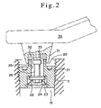
- FIG. 2 shows an embodiment of the pressure detecting means.
- the pressure measuring device indicated with a reference 30 is indicated with a dashed line.
- the pressure measuring device 30 is an ordinary digital pressure gauge. It has formed at the free end thereof a measurement opening 31 in which a leakage-preventive packing 32 is fitted.
- the leakage-preventive packing 32 has provided in the center thereof a tappet 33 to push in the valve rod 26.
- the packing 32 abuts the end face of the opening 25 in the valve body 21 to keep air-tightness.
- the portions of the pressure gauge 30 and valve body 21, which are engaged on each other, have to be designed to open the valve 23 while moving in close contact with each other. If the contact portion of either the measurement opening 31 in the pressure gauge 30 or the opening 25 in the valve body 21 can have provided thereon a leakage-preventive means formed from any easily deformable material, the engagement portions of the pressure gauge 30 and valve body 21 are not limited to those shown in FIG. 2 .
- FIG. 3 shows an example of such engagement portions in which the leakage-preventive means 34 is provided at the pressure detector 20.
- the check valve may be provided in a location where it communicates with a part of the air channel 13 in the spray gun where the pressure has to be measured.
- the opening 25 may be provided with a lid to prevent intrusion of a paint or inadvertent opening while the spray gun is being used.
- a removable means for screwing the pressure gauge 30 into the opening 25 in the valve body 21 may be provided, for example, a removable means for screwing the pressure gauge 30 into the opening 25 in the valve body 21.
- spray coating is effected by the spray gun provided with the pressure gauge 20 for pressure detection, and the air pressure can instantly be detected simply by pressing the pressure gauge 20 when it is necessary to measure and check the air pressure.
- the spray gun according to the present invention can of course be used as an ordinary spray gun. Also, since the spray gun has no pressure gauge installed thereon, it can easily be cleaned with a thinner or the like and also cleaned with a thinner sprayed to its entirety in an automatic cleaning facility, both with no problem.
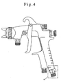
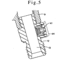
- FIGS. 4 and 5 show another embodiment of the present invention in which the spray gun having a pressure detector provided at the joint of the air intake of the spray gun.
- FIG. 4 is an external view of the spray gun.
- a pressure detector 41 is embedded in the connecting joint 12.
- the pressure detector 41 may have a similar check valve to that included in the embodiment having been described above with reference to FIG. 2 .
- a freely removable cap 44 may be provided as indicated with a chain line in FIG. 5 to prevent direct intrusion of a paint if necessary, the pressure detector 41 should desirably be easy to remove.
- the joint and the like of a conventional spray gun may be replaced with the joint of the spray gun according to the present invention even with no modification of the spray gun body.
- a valve to take out the spraying air pressure in the air channel is attached to the spray gun with the pressure gauge itself not being attached to the spray gun. It is not necessary to provide a pressure sensor, conversion circuit board, pressure indicator or the like on each spray gun. That is, the dedicated pressure measuring device is connected to the spray gun only when it is necessary to check the air pressure in the spray gun.
- the pressure measuring device may include a conversion means such as a power unit, control circuit board, for converting a pressure into an electrical signal for digital display, a storage/calculation means for using the pressure data as a control signal, etc. which are isolated from the spray gun itself.
- a pressure measuring feature may be included in the pressure measuring device itself without having to take in consideration the possible intrusion and adhesion of paint and solvent and the safety requirements, whereby preset paint spraying conditions can be stored, air pressure can easily be adjusted and the acceptability of an air pressure can be informed by alarming or the like.
- the present invention provides a spray gun permitting the user to easily check the spraying pressure as an important factor in the use of the spray gun whenever necessary and control the spraying pressure easily. Further, the present invention is applicable to a spray gun which has an air channel and uses a compressed air to spray a paint independently of the spray gun construction.
- the spray gun according to the present invention With only a minimum function such as an air pressure detection valve or sensor or the like being provided on the spray gun, the air pressure can readily be measured when necessary. For the air pressure measurement, there is required no large mechanism, and thus the spray gun according to the present invention is highly safe and durable. Also, since the spray gun has not to be used with the pressure measuring device kept installed, a single such device can be used in common with a plurality of spray guns. Namely, many spray guns can be used at low costs.
- a minimum function such as an air pressure detection valve or sensor or the like being provided on the spray gun
- the pressure measuring device such as the digital pressure gauge can be removed from the spray gun which is used as an ordinary one. Therefore, when the safety, device size and costs may not be taken in consideration, the pressure measuring device may have provided therein a storage unit, control feature and the like to standardize and manage the spray-coating work.
- the present invention has been described in detail concerning certain preferred embodiments thereof as examples with reference to the accompanying drawings. However, it should be understood by those ordinarily skilled in the art that the present invention is not limited to the embodiments but can be modified in various manners, constructed alternatively or embodied in various other forms without departing from the scope thereof as set forth and defined in the appended claims.
Landscapes
- Physics & Mathematics (AREA)
- Chemical & Material Sciences (AREA)
- Analytical Chemistry (AREA)
- General Physics & Mathematics (AREA)
- Fluid Mechanics (AREA)
- Nozzles (AREA)
Description
- The present invention relates to a spray gun for use with an air pressure detector which will not interfere with the user in routine paint-spraying operation and maintenance of the spray gun and on which an air pressure can be read easily and readily when necessary to control the spraying air pressure.
- The spray gun uses compressed air to atomize a paint for spraying to an object. The pressure of compressed air should always be monitored and controlled to assure a stable quality of painting with the spray gun. There are available some spray guns in which the user can check the spraying air pressure from a near position.
In the spray coating, both the quality of finished coating and scattering of the paint mist greatly depend upon the spraying air pressure used in the air spray gun to spray a paint to an object. Namely, it is well known that a higher air pressure will provide an increased energy for spraying and a finer atomization of the paint, which is generally contributed to an improved quality of paint coating. On the contrary, however, fine atomized mist of a paint is easily influenced by air flow to be more scattered. On this account, it is recommendable to use a spray gun with an appropriate spraying pressure selected correspondingly to a paint, object to be sprayed with the paint and coating conditions. For a quality spray coating, the spray gun should desirably be operated with monitoring the air pressure used for the spraying and under well-controlled conditions. In the recent spray guns, a lower air pressure is used to prevent the spray of paint from scattering and it is important to control the spraying air pressure since even a small change of the air pressure has a great influence on the coating quality. For example, in case objects carried one after another to a painting post are to be coated with paints different in color from each other, the paints have to be atomized under different conditions because of their different properties. In this case, the spraying pressure is changed from one to another of spray guns used with the respective paints in many cases. - The spraying air pressure is adjusted by a pressure reducing valve or the like before supplied to the spray gun via an air hose. Conventionally, the user of the spray gun rarely checks the spraying pressure in the course of a spray coating being made. As mentioned above, however, it is regarded as being very important to adjust the spraying pressure within a range set for assuring the stable quality of coating and thus it is necessary that the spraying pressure can be monitored from a position near the spray gun. Also, to assure a stable quality of the coating, it has been standardized to make a continuous spray coating under an air pressure adjusted to a predetermined range without reliance on the user's skill and intuition. Thus, it is necessary to monitor the air pressure in the course of a spray coating.
- Generally, a pressure gauge is installed directly to the spray gun in coating tests to acquire quantitative data. The pressure gauge used in such tests is a general-purpose one, and it is installed to a joint for the air hose of the spray gun. However, since the pressure gauge interferes with the user in the routine spray-coating work because of its weight and size, so it is rarely used in the actual coating.
- However, there has been proposed to use a small pressure gauge installed directly to a spray gun and which has no influence on the operability of the spray gun and on which the air pressure can be checked at any time even while the spray gun is being used (cf. Japanese Published Examined Utility Model No.
22277 1993 - Also, to solve the problem of the pressure gauge in the maintenance of the spray gun and accurately indicate a spraying pressure, there has been proposed in the Japanese Published Patent No.
506310 1993
EP-A-1375013 discloses a retrofittable pressure gauge attached to the body of a spray gun.US Patent 6585173 discloses a pressure gauge with its power supply and display, fitted into the grip of a spray gun.
The invention provides a spray gun as defined in Claim 1.
The present invention can overcome the above-mentioned drawbacks of the related art by providing a spray gun with which aspraying pressure can readily be checked when necessary and the coating work can be standardized.
The present invention can also provide a spray gun manufactured with a reduced cost and which needs no expensive associated facility and can be handled similarly to the conventional spray gun in the routine maintenance. - The present invention can also provide a spray gun designed to easily take the air pressure, thereby permitting to check pressure data and make a predetermined control of the pressure on the basis of the pressure data.
In the spray gun according to the present invention, the pressure measuring device is normally separated from the spray gun, and they are joined to each other when it is necessary to measure the air pressure. Of course, the spray gun may be used with the pressure measuring device kept joined to the spray gun whenever necessary.
The check valve may be embedded in a joint or the like at a grip end of the spray gun. The pressure detecting means may be removably connected to the pressure measuring device by abutting, screwing or fitting as long as a hermetic connection can be achieved between them. - These and other objects, features and advantages of the present invention will become more apparent from the ensuing detailed description of the preferred embodiments of the present invention when taken in conjunction with the accompanying drawings.
-
-
FIG. 1 is a schematic sectional view of the spray gun embodying the present invention; -
FIG. 2 is also a sectional view of an embodiment of the check valve; -
FIG. 3 is a sectional view of another embodiment of the check valve; -
FIG. 4 is an external view of the spray gun with the check valve means provided at the joint of the grip; and -
FIG. 5 is a sectional view, enlarged in scale, of a portion A inFIG. 4 . - Referring now to
FIG. 1 , there is schematically illustrated in the form of a sectional view one embodiment of the spray gun according to the present invention. The spray gun, generally indicated with a reference 1, is a manual type one operated with atrigger 2. As shown, the spray gun 1 includes an atomizer formed primarily from anatomization air cap 3 andpaint nozzle 4, agun barrel 8 formed from apaint supply adjuster 5, apattern adjuster 6 and anair valve 7, and agrip 9 extending backward and downward from thegun barrel 8. Thegrip 9 has formed at the bottom thereof a connectingjoint 12 forming anair intake 10 - There is formed an
air channel 13 in the gun barrel to connect theair intake 10 and atomizer to each other. There are disposed in a part of theair channel 13 theair valve 7 and a regulatingvalve 61 of thepattern adjuster 6. According to this embodiment, acheck valve 20 is provided between and above theair valve 7 and regulatingvalve 61. Thecheck valve 20 has abody 21 21 thereof fixed, by screwing tightly, in aspray gun body 11. There is provided avalve 23 engaged on aseat 22 to close the air channel. Thevalve 23 is always forced from the rear end thereof by anelastic member 24 to abut theseat 22. Thevalve 23 has formed at the front thereof arod 26 extending in an opening 25 formed in abody 21 of thevalve 23. When thevalve rod 26 is pushed in, thevalve 23 is opened to take the pressure from inside theair channel 13. - The opening 25 in the
valve body 21 andvalve rod 26 are determined in shape in relation to a portion, on which they are to be engaged, of a pressure measuring device.FIG. 2 shows an embodiment of the pressure detecting means. InFIG. 2 , the pressure measuring device indicated with areference 30 is indicated with a dashed line. Thepressure measuring device 30 is an ordinary digital pressure gauge. It has formed at the free end thereof a measurement opening 31 in which a leakage-preventive packing 32 is fitted. The leakage-preventive packing 32 has provided in the center thereof atappet 33 to push in thevalve rod 26. The packing 32 abuts the end face of theopening 25 in thevalve body 21 to keep air-tightness. When thepressure gauge 30 is further pressed until the packing 32 is compressed, thetappet 33 presses thevalve rod 26 and thus opens thevalve 23 so that the pressure inside theair channel 13 will act on themeasurement opening 31 in thepressure gauge 30. - The portions of the
pressure gauge 30 andvalve body 21, which are engaged on each other, have to be designed to open thevalve 23 while moving in close contact with each other. If the contact portion of either themeasurement opening 31 in thepressure gauge 30 or theopening 25 in thevalve body 21 can have provided thereon a leakage-preventive means formed from any easily deformable material, the engagement portions of thepressure gauge 30 andvalve body 21 are not limited to those shown inFIG. 2 .FIG. 3 shows an example of such engagement portions in which the leakage-preventive means 34 is provided at thepressure detector 20.
The check valve may be provided in a location where it communicates with a part of theair channel 13 in the spray gun where the pressure has to be measured. Depending upon the location of thecheck valve 20, there may be provided a separate liaison channel which provides a connection between thecheck valve 20 andair channel 13, for example. Also, theopening 25 may be provided with a lid to prevent intrusion of a paint or inadvertent opening while the spray gun is being used. Further, to provisionally fix thepressure gauge 30, there may be provided, for example, a removable means for screwing thepressure gauge 30 into theopening 25 in thevalve body 21. - As mentioned above, spray coating is effected by the spray gun provided with the
pressure gauge 20 for pressure detection, and the air pressure can instantly be detected simply by pressing thepressure gauge 20 when it is necessary to measure and check the air pressure. As mentioned above, different from the conventional spray gun in which the air hose has to be disconnected for the purpose of installing the pressure gauge, it is not necessary in the spray gun according to the present invention to dismount the pressure gauge once installed for the reason that the latter will degrade the operability of the spray gun in spray coating. The spray gun according to the present invention can of course be used as an ordinary spray gun.
Also, since the spray gun has no pressure gauge installed thereon, it can easily be cleaned with a thinner or the like and also cleaned with a thinner sprayed to its entirety in an automatic cleaning facility, both with no problem. -
FIGS. 4 and5 show another embodiment of the present invention in which the spray gun having a pressure detector provided at the joint of the air intake of the spray gun.FIG. 4 is an external view of the spray gun. As shown in detail in the sectional view inFIG. 5 , apressure detector 41 is embedded in the connecting joint 12. Thepressure detector 41 may have a similar check valve to that included in the embodiment having been described above with reference toFIG. 2 . Although a freelyremovable cap 44 may be provided as indicated with a chain line inFIG. 5 to prevent direct intrusion of a paint if necessary, thepressure detector 41 should desirably be easy to remove. With thepressure detector 41 being embedded in a part of a fixture connecting to the air channel in the spray gun as in this embodiment, the joint and the like of a conventional spray gun may be replaced with the joint of the spray gun according to the present invention even with no modification of the spray gun body. - According to the present invention, a valve to take out the spraying air pressure in the air channel is attached to the spray gun with the pressure gauge itself not being attached to the spray gun. It is not necessary to provide a pressure sensor, conversion circuit board, pressure indicator or the like on each spray gun. That is, the dedicated pressure measuring device is connected to the spray gun only when it is necessary to check the air pressure in the spray gun.
- Further, the pressure measuring device may include a conversion means such as a power unit, control circuit board, for converting a pressure into an electrical signal for digital display, a storage/calculation means for using the pressure data as a control signal, etc. which are isolated from the spray gun itself. Thus, a pressure measuring feature may be included in the pressure measuring device itself without having to take in consideration the possible intrusion and adhesion of paint and solvent and the safety requirements, whereby preset paint spraying conditions can be stored, air pressure can easily be adjusted and the acceptability of an air pressure can be informed by alarming or the like.
- As having been described in the foregoing, the present invention provides a spray gun permitting the user to easily check the spraying pressure as an important factor in the use of the spray gun whenever necessary and control the spraying pressure easily. Further, the present invention is applicable to a spray gun which has an air channel and uses a compressed air to spray a paint independently of the spray gun construction.
- According to the present invention, with only a minimum function such as an air pressure detection valve or sensor or the like being provided on the spray gun, the air pressure can readily be measured when necessary. For the air pressure measurement, there is required no large mechanism, and thus the spray gun according to the present invention is highly safe and durable. Also, since the spray gun has not to be used with the pressure measuring device kept installed, a single such device can be used in common with a plurality of spray guns. Namely, many spray guns can be used at low costs.
- Further, the pressure measuring device such as the digital pressure gauge can be removed from the spray gun which is used as an ordinary one. Therefore, when the safety, device size and costs may not be taken in consideration, the pressure measuring device may have provided therein a storage unit, control feature and the like to standardize and manage the spray-coating work.
In the foregoing, the present invention has been described in detail concerning certain preferred embodiments thereof as examples with reference to the accompanying drawings. However, it should be understood by those ordinarily skilled in the art that the present invention is not limited to the embodiments but can be modified in various manners, constructed alternatively or embodied in various other forms without departing from the scope thereof as set forth and defined in the appended claims.
Claims (2)
- A spray gun (1) including an atomizer (3, 4) to atomize paint with compressed air, an air intake for compressed air from the atomizer, and an air channel (13) which provides a communication between the atomizer and air intake, characterized in that there is further provided a check valve (20) facing at one side thereof a part of the air channel and at the other side the outside of the spray gun, the check valve being constructed so that the air pressure in the air channel acts on an external pressure measuring device (30) when the check valve is connected to the pressure measuring device, so that it is opened under pressure applied from outside, so that the air channel is isolated from the outside when the check valve is disconnected from the pressure measuring device, and so that the check valve is closed as the pressure from the pressure measuring device is removed.
- A spray gun according to Claim 1, wherein the check valve (41) is embedded in a joint (12) which is the air intake (10).
Priority Applications (2)
| Application Number | Priority Date | Filing Date | Title |
|---|---|---|---|
| EP20040254318 EP1618963B1 (en) | 2004-07-19 | 2004-07-19 | Spray gun with adaptable air pressure indication means |
| DE200460018301 DE602004018301D1 (en) | 2004-07-19 | 2004-07-19 | Spray gun with adaptable air pressure indicating means |
Applications Claiming Priority (1)
| Application Number | Priority Date | Filing Date | Title |
|---|---|---|---|
| EP20040254318 EP1618963B1 (en) | 2004-07-19 | 2004-07-19 | Spray gun with adaptable air pressure indication means |
Publications (2)
| Publication Number | Publication Date |
|---|---|
| EP1618963A1 EP1618963A1 (en) | 2006-01-25 |
| EP1618963B1 true EP1618963B1 (en) | 2008-12-10 |
Family
ID=34930501
Family Applications (1)
| Application Number | Title | Priority Date | Filing Date |
|---|---|---|---|
| EP20040254318 Expired - Lifetime EP1618963B1 (en) | 2004-07-19 | 2004-07-19 | Spray gun with adaptable air pressure indication means |
Country Status (2)
| Country | Link |
|---|---|
| EP (1) | EP1618963B1 (en) |
| DE (1) | DE602004018301D1 (en) |
Families Citing this family (3)
| Publication number | Priority date | Publication date | Assignee | Title |
|---|---|---|---|---|
| IT201700072417A1 (en) * | 2017-06-28 | 2018-12-28 | Anest Iwata Strategic Center S R L | MANUAL SPRAY PAINT GUN |
| DE102020106173A1 (en) | 2020-03-06 | 2021-09-09 | Sata Gmbh & Co. Kg | Spray gun, pressure measuring device for a spray gun and method for designing a spray gun |
| DE102023135506A1 (en) * | 2023-12-18 | 2025-06-18 | Sata Gmbh & Co. Kg | paint spray gun |
Family Cites Families (5)
| Publication number | Priority date | Publication date | Assignee | Title |
|---|---|---|---|---|
| JPH0522277Y2 (en) | 1987-04-24 | 1993-06-08 | ||
| JPH056310A (en) | 1991-06-27 | 1993-01-14 | Toshiba Corp | Electronic device |
| DE10135104C1 (en) | 2001-07-19 | 2002-09-12 | Sata Farbspritztechnik | Spray Gun |
| GB2389908B (en) | 2002-06-18 | 2005-05-18 | Itw Ltd | Pressure gauge |
| FR2841093B1 (en) * | 2002-06-24 | 2007-05-18 | Denis Deleval | WATERING DEVICE COMPRISING A SENSOR SENSITIVE TO THE QUANTITY OF DISTRIBUTED WATER AND CONNECTION COMPRISING A FLOW SENSOR |
-
2004
- 2004-07-19 DE DE200460018301 patent/DE602004018301D1/en not_active Expired - Lifetime
- 2004-07-19 EP EP20040254318 patent/EP1618963B1/en not_active Expired - Lifetime
Also Published As
| Publication number | Publication date |
|---|---|
| DE602004018301D1 (en) | 2009-01-22 |
| EP1618963A1 (en) | 2006-01-25 |
Similar Documents
| Publication | Publication Date | Title |
|---|---|---|
| EP1477232B1 (en) | Spray gun with pressure display | |
| JP3677044B2 (en) | Monitor for fluid distributor | |
| EP1375013B1 (en) | Pressure gauge | |
| US6845924B2 (en) | Spray pistol | |
| US7017838B2 (en) | Spray gun | |
| JP5622839B2 (en) | Pressure gauge removable spray gun | |
| US5333506A (en) | Gauge for measuring the atomization air pressure in a paint spray gun | |
| US6585173B2 (en) | Paint spray gun | |
| US20230107860A1 (en) | Spray gun, pressure measuring device for a spray gun and method for developing a spray gun | |
| EP1618963A1 (en) | Spray gun with adaptable air pressure indication means | |
| EP0845102A2 (en) | Fuel cap leakage tester | |
| CN100522384C (en) | Spray gun with gas pressure detector | |
| US20050233063A1 (en) | Coating operation pollutant emission measurement and recording system and method | |
| JP2004330168A (en) | Spray gun equipped with pressure detection means | |
| JPH0631216A (en) | Detecting device for condition of nozzle of painting spray gun | |
| KR20040013239A (en) | Level Sensor Cleaning Device of Powder Coating Machine | |
| JP2025174933A (en) | Optical fiber-based flowmeter for hazardous environments | |
| JP3046861U (en) | Paint quantity check device | |
| AU2013245521A1 (en) | Device for installation in an air-operated spray gun | |
| CN121452400A (en) | Measurement control valve capable of controlling opening and intelligently calculating flow | |
| HK1188476A1 (en) | Liquid metering pump, and device for detecting the variation in pressure for such a pump | |
| HK1188476B (en) | Liquid metering pump, and device for detecting the variation in pressure for such a pump | |
| GB2266376A (en) | Pressure test gauge | |
| ITSV980025A1 (en) | ELECTRONIC PRESSURE GAUGE AND DEVICE FOR SIGNALING THE INFLATION PRESSURE AND INFLATION DEVICE, IN |
Legal Events
| Date | Code | Title | Description |
|---|---|---|---|
| PUAI | Public reference made under article 153(3) epc to a published international application that has entered the european phase |
Free format text: ORIGINAL CODE: 0009012 |
|
| AK | Designated contracting states |
Kind code of ref document: A1 Designated state(s): AT BE BG CH CY CZ DE DK EE ES FI FR GB GR HU IE IT LI LU MC NL PL PT RO SE SI SK TR |
|
| AX | Request for extension of the european patent |
Extension state: AL HR LT LV MK |
|
| 17P | Request for examination filed |
Effective date: 20060711 |
|
| 17Q | First examination report despatched |
Effective date: 20060811 |
|
| AKX | Designation fees paid |
Designated state(s): DE FR GB IT |
|
| GRAP | Despatch of communication of intention to grant a patent |
Free format text: ORIGINAL CODE: EPIDOSNIGR1 |
|
| GRAS | Grant fee paid |
Free format text: ORIGINAL CODE: EPIDOSNIGR3 |
|
| GRAS | Grant fee paid |
Free format text: ORIGINAL CODE: EPIDOSNIGR3 |
|
| GRAA | (expected) grant |
Free format text: ORIGINAL CODE: 0009210 |
|
| AK | Designated contracting states |
Kind code of ref document: B1 Designated state(s): DE FR GB IT |
|
| REG | Reference to a national code |
Ref country code: GB Ref legal event code: FG4D |
|
| REF | Corresponds to: |
Ref document number: 602004018301 Country of ref document: DE Date of ref document: 20090122 Kind code of ref document: P |
|
| PLBE | No opposition filed within time limit |
Free format text: ORIGINAL CODE: 0009261 |
|
| STAA | Information on the status of an ep patent application or granted ep patent |
Free format text: STATUS: NO OPPOSITION FILED WITHIN TIME LIMIT |
|
| 26N | No opposition filed |
Effective date: 20090911 |
|
| REG | Reference to a national code |
Ref country code: FR Ref legal event code: ST Effective date: 20100331 |
|
| PG25 | Lapsed in a contracting state [announced via postgrant information from national office to epo] |
Ref country code: FR Free format text: LAPSE BECAUSE OF NON-PAYMENT OF DUE FEES Effective date: 20090731 |
|
| PG25 | Lapsed in a contracting state [announced via postgrant information from national office to epo] |
Ref country code: IT Free format text: LAPSE BECAUSE OF FAILURE TO SUBMIT A TRANSLATION OF THE DESCRIPTION OR TO PAY THE FEE WITHIN THE PRESCRIBED TIME-LIMIT Effective date: 20081210 |
|
| PGFP | Annual fee paid to national office [announced via postgrant information from national office to epo] |
Ref country code: DE Payment date: 20180723 Year of fee payment: 15 |
|
| PGFP | Annual fee paid to national office [announced via postgrant information from national office to epo] |
Ref country code: GB Payment date: 20180719 Year of fee payment: 15 |
|
| REG | Reference to a national code |
Ref country code: DE Ref legal event code: R119 Ref document number: 602004018301 Country of ref document: DE |
|
| GBPC | Gb: european patent ceased through non-payment of renewal fee |
Effective date: 20190719 |
|
| PG25 | Lapsed in a contracting state [announced via postgrant information from national office to epo] |
Ref country code: GB Free format text: LAPSE BECAUSE OF NON-PAYMENT OF DUE FEES Effective date: 20190719 Ref country code: DE Free format text: LAPSE BECAUSE OF NON-PAYMENT OF DUE FEES Effective date: 20200201 |