EP1375013A2 - Pressure gauge - Google Patents
Pressure gauge Download PDFInfo
- Publication number
- EP1375013A2 EP1375013A2 EP03252727A EP03252727A EP1375013A2 EP 1375013 A2 EP1375013 A2 EP 1375013A2 EP 03252727 A EP03252727 A EP 03252727A EP 03252727 A EP03252727 A EP 03252727A EP 1375013 A2 EP1375013 A2 EP 1375013A2
- Authority
- EP
- European Patent Office
- Prior art keywords
- pressure gauge
- spray gun
- valve
- pressure
- spreader
- Prior art date
- Legal status (The legal status is an assumption and is not a legal conclusion. Google has not performed a legal analysis and makes no representation as to the accuracy of the status listed.)
- Granted
Links
- 239000007921 spray Substances 0.000 claims abstract description 76
- 239000012530 fluid Substances 0.000 claims abstract description 67
- 238000004891 communication Methods 0.000 claims abstract description 12
- 239000004973 liquid crystal related substance Substances 0.000 claims description 3
- 239000004065 semiconductor Substances 0.000 claims description 3
- RYGMFSIKBFXOCR-UHFFFAOYSA-N Copper Chemical compound [Cu] RYGMFSIKBFXOCR-UHFFFAOYSA-N 0.000 description 10
- 229910052802 copper Inorganic materials 0.000 description 10
- 239000010949 copper Substances 0.000 description 10
- 239000002184 metal Substances 0.000 description 10
- 229910052751 metal Inorganic materials 0.000 description 10
- 238000007493 shaping process Methods 0.000 description 6
- DCPDZFRGNJDWPP-UHFFFAOYSA-N 1,2,3,4,5-pentachloro-6-(2,4,5-trichlorophenyl)benzene Chemical compound C1=C(Cl)C(Cl)=CC(Cl)=C1C1=C(Cl)C(Cl)=C(Cl)C(Cl)=C1Cl DCPDZFRGNJDWPP-UHFFFAOYSA-N 0.000 description 5
- 238000011144 upstream manufacturing Methods 0.000 description 5
- 239000002245 particle Substances 0.000 description 2
- 238000000889 atomisation Methods 0.000 description 1
- 230000000903 blocking effect Effects 0.000 description 1
- 239000000919 ceramic Substances 0.000 description 1
- 239000011521 glass Substances 0.000 description 1
- 231100001261 hazardous Toxicity 0.000 description 1
- 230000003993 interaction Effects 0.000 description 1
- 238000012986 modification Methods 0.000 description 1
- 230000004048 modification Effects 0.000 description 1
- 239000003973 paint Substances 0.000 description 1
- 230000000717 retained effect Effects 0.000 description 1
- 238000005507 spraying Methods 0.000 description 1
- 239000000758 substrate Substances 0.000 description 1
Images


Classifications
-
- G—PHYSICS
- G01—MEASURING; TESTING
- G01L—MEASURING FORCE, STRESS, TORQUE, WORK, MECHANICAL POWER, MECHANICAL EFFICIENCY, OR FLUID PRESSURE
- G01L19/00—Details of, or accessories for, apparatus for measuring steady or quasi-steady pressure of a fluent medium insofar as such details or accessories are not special to particular types of pressure gauges
- G01L19/14—Housings
-
- B—PERFORMING OPERATIONS; TRANSPORTING
- B05—SPRAYING OR ATOMISING IN GENERAL; APPLYING FLUENT MATERIALS TO SURFACES, IN GENERAL
- B05B—SPRAYING APPARATUS; ATOMISING APPARATUS; NOZZLES
- B05B12/00—Arrangements for controlling delivery; Arrangements for controlling the spray area
- B05B12/004—Arrangements for controlling delivery; Arrangements for controlling the spray area comprising sensors for monitoring the delivery, e.g. by displaying the sensed value or generating an alarm
- B05B12/006—Pressure or flow rate sensors
- B05B12/008—Pressure or flow rate sensors integrated in or attached to a discharge apparatus, e.g. a spray gun
-
- B—PERFORMING OPERATIONS; TRANSPORTING
- B05—SPRAYING OR ATOMISING IN GENERAL; APPLYING FLUENT MATERIALS TO SURFACES, IN GENERAL
- B05B—SPRAYING APPARATUS; ATOMISING APPARATUS; NOZZLES
- B05B7/00—Spraying apparatus for discharge of liquids or other fluent materials from two or more sources, e.g. of liquid and air, of powder and gas
- B05B7/02—Spray pistols; Apparatus for discharge
- B05B7/12—Spray pistols; Apparatus for discharge designed to control volume of flow, e.g. with adjustable passages
-
- B—PERFORMING OPERATIONS; TRANSPORTING
- B05—SPRAYING OR ATOMISING IN GENERAL; APPLYING FLUENT MATERIALS TO SURFACES, IN GENERAL
- B05B—SPRAYING APPARATUS; ATOMISING APPARATUS; NOZZLES
- B05B7/00—Spraying apparatus for discharge of liquids or other fluent materials from two or more sources, e.g. of liquid and air, of powder and gas
- B05B7/24—Spraying apparatus for discharge of liquids or other fluent materials from two or more sources, e.g. of liquid and air, of powder and gas with means, e.g. a container, for supplying liquid or other fluent material to a discharge device
- B05B7/2402—Apparatus to be carried on or by a person, e.g. by hand; Apparatus comprising containers fixed to the discharge device
- B05B7/2478—Gun with a container which, in normal use, is located above the gun
-
- G—PHYSICS
- G01—MEASURING; TESTING
- G01L—MEASURING FORCE, STRESS, TORQUE, WORK, MECHANICAL POWER, MECHANICAL EFFICIENCY, OR FLUID PRESSURE
- G01L19/00—Details of, or accessories for, apparatus for measuring steady or quasi-steady pressure of a fluent medium insofar as such details or accessories are not special to particular types of pressure gauges
- G01L19/0007—Fluidic connecting means
-
- B—PERFORMING OPERATIONS; TRANSPORTING
- B05—SPRAYING OR ATOMISING IN GENERAL; APPLYING FLUENT MATERIALS TO SURFACES, IN GENERAL
- B05B—SPRAYING APPARATUS; ATOMISING APPARATUS; NOZZLES
- B05B7/00—Spraying apparatus for discharge of liquids or other fluent materials from two or more sources, e.g. of liquid and air, of powder and gas
- B05B7/02—Spray pistols; Apparatus for discharge
- B05B7/08—Spray pistols; Apparatus for discharge with separate outlet orifices, e.g. to form parallel jets, i.e. the axis of the jets being parallel, to form intersecting jets, i.e. the axis of the jets converging but not necessarily intersecting at a point
- B05B7/0807—Spray pistols; Apparatus for discharge with separate outlet orifices, e.g. to form parallel jets, i.e. the axis of the jets being parallel, to form intersecting jets, i.e. the axis of the jets converging but not necessarily intersecting at a point to form intersecting jets
- B05B7/0815—Spray pistols; Apparatus for discharge with separate outlet orifices, e.g. to form parallel jets, i.e. the axis of the jets being parallel, to form intersecting jets, i.e. the axis of the jets converging but not necessarily intersecting at a point to form intersecting jets with at least one gas jet intersecting a jet constituted by a liquid or a mixture containing a liquid for controlling the shape of the latter
Definitions
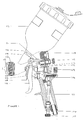
- Figure 1 shows a spray gun comprising a gun body 101, defining an interior space 102 through which compressed air can be passed, having an integral handle 111 depending from adjacent a first end of the gun body 116 and an air cap 112 secured to an opposing second end of the gun body 117 by a retaining ring 113.
- the microprocessor When the microprocessor receives successive alternating inputs from each of the two circuits, the microprocessor energises the pressure transducer 209. When the alternating input signals cease for a predetermined time, due to the spray gun being motionless, the microprocessor de-energises the pressure transducer 209.
- the pressure gauge 109 can also be mounted, in a similar manner as described hereinabove, on spray guns of alternative design and layout.
- spray guns include that illustrated in DE 100 31 858 A where the longitudinal axis of the spreader valve is substantially orthogonal to the plane of the spray gun.
- the trigger operated fluid valve of the spray gun is in a similar location to that shown in Figure 1.
- the compressed air inlet pressure reducing valve is, however, sited on the gun body between the trigger operated fluid valve and a handle pendant from one end of the gun body.
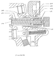
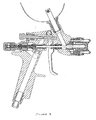
- Another design of gun on which the pressure gauge of the invention can be mounted is that shown in Figure 7 where the trigger operated shut off valve and trigger operated fluid valve are concentric.
- a further spray gun layout suitable for accommodating the pressure gauge of the invention is a spray gun combining concentric trigger operated compressed air and trigger operated fluid valves with a spreader valve whose longitudinal axis is substantially orthogonal to the plane of the spray gun.
Landscapes
- Physics & Mathematics (AREA)
- General Physics & Mathematics (AREA)
- Chemical & Material Sciences (AREA)
- Analytical Chemistry (AREA)
- Fluid Mechanics (AREA)
- Nozzles (AREA)
- Measuring Fluid Pressure (AREA)
- Glass Compositions (AREA)
- Electrical Discharge Machining, Electrochemical Machining, And Combined Machining (AREA)
- Details Or Accessories Of Spraying Plant Or Apparatus (AREA)
- Lubricants (AREA)
Abstract
Description
Claims (11)
- A retrofittable pressure gauge for a spray gun comprising a pressure sensor (209), located in a pressure chamber, a power source (211) and a display unit (204), all enclosed within a case (201), a passageway (301) providing fluid communication between the pressure chamber and a pressurised interior space (102) of a spray gun when the gauge is mounted on a spray gun and a means for attachment to a spray gun, characterized in that the means for attachment comprises a mounting fixture (212) configured for mounting the pressure gauge (109) at a spreader valve (103) or a trigger operated fluid valve (107) of a spray gun.
- A pressure gauge according to claim 1 characterized in that the mounting fixture (212) comprises a mounting fixture bore (213) through which at least a part of the spreader valve or trigger operated fluid valve can pass thereby mounting the pressure gauge (109) at the spreader valve (103) or the trigger operated fluid valve (107).
- A pressure gauge according to claim 1 or claim 2 characterized in that the passageway (301) provides fluid communication between the pressure chamber and the mounting fixture bore (213).
- A pressure gauge according to any one of the preceding claims characterized in that the mounting fixture bore (213) and the part of the spreader valve or trigger operated fluid valve which can pass through the mounting fixture bore (213) define an annular space (418) in communication with the passageway (301).
- A pressure gauge according to any one of the preceding claims characterized in that the pressure gauge (109) is analogue or digital.
- A pressure gauge according to any one of the preceding claims characterized in that the pressure gauge (109) further comprises a movement detector switch which activates the pressure sensor (209) only when the pressure gauge (109) is subject to movement.
- A pressure gauge according to any one of the preceding claims characterized in that the pressure sensor (209) comprises a semiconductor strain device.
- A pressure gauge according to any one of the preceding claims characterized in that the display unit (204) is a liquid crystal display.
- A pressure gauge according to any one of the preceding claims characterized in that the pressure gauge (109) further comprising a printed circuit board mounting a microprocessor (203).
- A kit comprising a pressure gauge (109) according to any one of the preceding claims and a spreader valve bushing (407) or a trigger operated fluid valve bushing (603), the spreader valve bushing (407) or trigger operated fluid valve bushing (603) comprising a channel (409, 608), in substantial alignment with the longitudinal axis of the spreader valve bushing or trigger operated fluid valve bushing, which, when the spreader valve bushing (407) or trigger operated fluid valve bushing (603) is fitted into a spray gun, allows fluid communication between the pressurised interior space (102) and the annular space (418, 610).
- A spray gun comprising a pressure gauge according to any one of claims 1 to 9.
Applications Claiming Priority (2)
| Application Number | Priority Date | Filing Date | Title |
|---|---|---|---|
| GB0213913 | 2002-06-18 | ||
| GB0213913A GB2389908B (en) | 2002-06-18 | 2002-06-18 | Pressure gauge |
Publications (3)
| Publication Number | Publication Date |
|---|---|
| EP1375013A2 true EP1375013A2 (en) | 2004-01-02 |
| EP1375013A3 EP1375013A3 (en) | 2006-08-09 |
| EP1375013B1 EP1375013B1 (en) | 2008-07-23 |
Family
ID=9938746
Family Applications (1)
| Application Number | Title | Priority Date | Filing Date |
|---|---|---|---|
| EP03252727A Expired - Lifetime EP1375013B1 (en) | 2002-06-18 | 2003-04-30 | Pressure gauge |
Country Status (9)
| Country | Link |
|---|---|
| US (3) | US7216813B2 (en) |
| EP (1) | EP1375013B1 (en) |
| JP (1) | JP4276001B2 (en) |
| AT (1) | ATE401969T1 (en) |
| CA (1) | CA2432498C (en) |
| DE (1) | DE60322299D1 (en) |
| ES (1) | ES2311085T3 (en) |
| GB (1) | GB2389908B (en) |
| PT (1) | PT1375013E (en) |
Cited By (9)
| Publication number | Priority date | Publication date | Assignee | Title |
|---|---|---|---|---|
| WO2005082544A1 (en) | 2004-02-19 | 2005-09-09 | Itw Limited | Pressure monitoring device for a paint spray gun |
| EP1618963A1 (en) | 2004-07-19 | 2006-01-25 | Anest Iwata Corporation | Spray gun with adaptable air pressure indication means |
| WO2006021860A1 (en) * | 2004-08-25 | 2006-03-02 | Itw Limited | Air valve for a paint gun |
| CN100522384C (en) * | 2004-08-04 | 2009-08-05 | 阿耐斯特岩田株式会社 | Spray gun with gas pressure detector |
| CN104154694A (en) * | 2014-08-19 | 2014-11-19 | 广东志高空调有限公司 | A snowing device and a climatic chamber |
| EP2918347A1 (en) * | 2014-03-14 | 2015-09-16 | Anest Iwata Corporation | Pressure sensor unit |
| CN109562402A (en) * | 2016-08-09 | 2019-04-02 | 阿尔弗雷德·卡赫欧洲两合公司 | The spray gun of high-pressure cleaning appliance |
| WO2020207103A1 (en) * | 2019-04-12 | 2020-10-15 | 浙江火山机械有限公司 | Spray gun having convenient switch switching safety |
| US10987690B2 (en) | 2017-06-28 | 2021-04-27 | ANEST IWATA Strategic Center S.r.l | Manually-operated paint spray gun |
Families Citing this family (54)
| Publication number | Priority date | Publication date | Assignee | Title |
|---|---|---|---|---|
| US20070137942A1 (en) * | 2004-06-24 | 2007-06-21 | Weems R M | Battery powered grease gun with strain gauge based pressure transducer |
| US7188581B1 (en) | 2005-10-21 | 2007-03-13 | Brunswick Corporation | Marine drive with integrated trim tab |
| US7234983B2 (en) * | 2005-10-21 | 2007-06-26 | Brunswick Corporation | Protective marine vessel and drive |
| US7294031B1 (en) | 2005-10-21 | 2007-11-13 | Brunswick Corporation | Marine drive grommet seal |
| US7563299B2 (en) * | 2005-11-08 | 2009-07-21 | Illinois Tool Works Inc. | Filtering apparatus, filter regulator for use with spray gun and spraying system using the same |
| US7509864B2 (en) * | 2006-04-24 | 2009-03-31 | Illinois Tool Works Inc, | Paint spray gun with digital pressure gauge and relative humidity indicator removably mounted thereon |
| DE502007000825D1 (en) | 2006-12-05 | 2009-07-16 | Sata Gmbh & Co Kg | Ventilation for the gravity cup of a paint spray gun |
| GB2446785A (en) * | 2007-02-20 | 2008-08-27 | Sandra Quirk | Foam spraying device |
| US20090026288A1 (en) * | 2007-07-25 | 2009-01-29 | Hsien-Chao Shih | Double Atomization Paint Spray Gun |
| USD574926S1 (en) * | 2007-11-30 | 2008-08-12 | Kuan Chang Co., Ltd | Paint cup for a spray gun |
| EP2265387B1 (en) | 2008-03-12 | 2015-05-06 | Jeffrey D. Fox | Disposable spray gun cartridge |
| US7793549B1 (en) * | 2008-10-14 | 2010-09-14 | Chien-Chih Yeh | Pressure gauge locking structure of paintball gun |
| DE202008014389U1 (en) | 2008-10-29 | 2010-04-08 | Sata Gmbh & Co. Kg | Gravity cup for a paint spray gun |
| DE202009006562U1 (en) * | 2009-05-07 | 2010-09-30 | Sata Gmbh & Co. Kg | Spray gun with pressure measuring device |
| DE102009020194A1 (en) * | 2009-05-07 | 2010-11-11 | Sata Gmbh & Co. Kg | Spray gun with pressure measuring device |
| AU2013206665B2 (en) * | 2009-05-07 | 2015-07-30 | Sata Gmbh & Co. Kg | Spray gun with a pressure measuring device |
| DE102009032399A1 (en) | 2009-07-08 | 2011-01-13 | Sata Gmbh & Co. Kg | Spray Gun |
| DE102009058930B4 (en) * | 2009-12-17 | 2011-11-10 | Pierburg Gmbh | Valve device for internal combustion engines |
| US20140069506A1 (en) * | 2010-12-17 | 2014-03-13 | Partners In Innovation Limited, Llc | Water management control device for watering devices |
| DE202010007355U1 (en) | 2010-05-28 | 2011-10-20 | Sata Gmbh & Co. Kg | Nozzle head for a spraying device |
| US9333519B2 (en) | 2010-12-02 | 2016-05-10 | Sata Gmbh & Co. Kg | Spray gun and accessories |
| CN107537707B (en) | 2011-06-30 | 2021-09-03 | 萨塔有限两合公司 | Spray gun, spray medium guide unit, cover, base body and related method |
| US20140084075A1 (en) * | 2012-09-21 | 2014-03-27 | Akron Brass Company | Nozzle fluid flow indicator system |
| CA155474S (en) | 2013-09-27 | 2015-08-27 | Sata Gmbh & Co Kg | Spray gun |
| DE202013105779U1 (en) | 2013-12-18 | 2015-03-19 | Sata Gmbh & Co. Kg | Air nozzle termination for a paint spray gun |
| CN105289870B (en) | 2014-07-31 | 2019-09-24 | 萨塔有限两合公司 | Manufacturing method of spray gun, spray gun, spray gun body and cover |
| USD758537S1 (en) | 2014-07-31 | 2016-06-07 | Sata Gmbh & Co. Kg | Paint spray gun rear portion |
| CA159961S (en) | 2014-07-31 | 2015-07-17 | Sata Gmbh & Co Kg | Spray gun |
| USD768820S1 (en) | 2014-09-03 | 2016-10-11 | Sata Gmbh & Co. Kg | Paint spray gun with pattern |
| DE102014115789A1 (en) * | 2014-10-30 | 2016-05-04 | Alfred Kärcher Gmbh & Co. Kg | Spray gun for high-pressure cleaning device |
| JP1535002S (en) | 2015-03-17 | 2015-10-13 | ||
| DE102015006484A1 (en) | 2015-05-22 | 2016-11-24 | Sata Gmbh & Co. Kg | Nozzle arrangement for a spray gun, in particular paint spray gun and spray gun, in particular paint spray gun |
| DE102015016474A1 (en) | 2015-12-21 | 2017-06-22 | Sata Gmbh & Co. Kg | Air cap and nozzle assembly for a spray gun and spray gun |
| CN205995666U (en) | 2016-08-19 | 2017-03-08 | 萨塔有限两合公司 | Spray gun and its trigger |
| CN205966208U (en) | 2016-08-19 | 2017-02-22 | 萨塔有限两合公司 | Hood subassembly and spray gun |
| USD863016S1 (en) | 2017-09-19 | 2019-10-15 | Campbell Hausfeld, Llc | Inflation gun |
| CN112533705B (en) | 2018-08-01 | 2023-07-04 | 萨塔有限两合公司 | Nozzle bank for spray gun, spray gun system, method for manufacturing nozzle modules, method for selecting nozzle modules from nozzle banks for painting tasks, selection system and computer program product |
| DE102018118738A1 (en) | 2018-08-01 | 2020-02-06 | Sata Gmbh & Co. Kg | Base body for a spray gun, spray guns, spray gun set, method for producing a base body for a spray gun and method for converting a spray gun |
| DE102018118737A1 (en) | 2018-08-01 | 2020-02-06 | Sata Gmbh & Co. Kg | Nozzle for a spray gun, nozzle set for a spray gun, spray guns and method for producing a nozzle for a spray gun |
| DE102018122004A1 (en) | 2018-09-10 | 2020-03-12 | Sata Gmbh & Co. Kg | Spray gun, material application system and method for its operation |
| DE102020106172A1 (en) | 2020-03-06 | 2021-09-09 | Sata Gmbh & Co. Kg | Spray gun, in particular paint spray gun that atomizes compressed air, in particular hand-held paint spray gun that atomizes compressed air |
| USD1047080S1 (en) * | 2020-04-29 | 2024-10-15 | Ac Avalanche, Llc | Dispenser housing |
| USD943710S1 (en) * | 2020-05-19 | 2022-02-15 | Zhejiang Rongpeng Air Tools Co., Ltd. | Paint sprayer |
| TWI730844B (en) * | 2020-07-16 | 2021-06-11 | 輝寶實業有限公司 | Pressure regulating method and device of spray paint gun |
| DE102020123769A1 (en) | 2020-09-11 | 2022-03-17 | Sata Gmbh & Co. Kg | Sealing element for sealing a transition between a base body of a spray gun and an add-on part of a spray gun, add-on part, in particular paint nozzle arrangement, for a spray gun and spray gun, in particular paint spray gun |
| CN112923623B (en) * | 2021-02-01 | 2022-06-07 | 西安交通大学 | Snow making machine with high snow making rate and control method and working method thereof |
| USD1042735S1 (en) * | 2021-05-07 | 2024-09-17 | Weicon Gmbh & Co Kg | Dosing closure |
| USD950679S1 (en) * | 2021-06-16 | 2022-05-03 | Zhejiang Rongpeng Air Tools Co., Ltd. | Paint spray gun |
| USD1046076S1 (en) | 2021-10-15 | 2024-10-08 | Sata Gmbh & Co. Kg | Spray gun |
| GB2614258B (en) * | 2021-12-22 | 2024-10-16 | Scarab Solutions Ltd | Monitoring apparatus and method for monitoring operation of fluid dispensing system |
| USD957573S1 (en) * | 2022-03-30 | 2022-07-12 | Corey CRAIG | Intelligent spraying apparatus |
| CN217699657U (en) * | 2022-06-29 | 2022-11-01 | 浙江荣鹏气动工具股份有限公司 | Pneumatic spray gun pressure regulating valve assembly formed by assembling |
| US20240278280A1 (en) * | 2023-02-17 | 2024-08-22 | Telebrands Corp. | Adjustable handle |
| DE102023135508A1 (en) * | 2023-12-18 | 2025-06-18 | Sata Gmbh & Co. Kg | paint spray gun |
Citations (3)
| Publication number | Priority date | Publication date | Assignee | Title |
|---|---|---|---|---|
| EP0526525A1 (en) | 1990-04-24 | 1993-02-10 | Itw Ltd | Spray gun comprising miniature electronic pressure gauge. |
| DE10031857A1 (en) | 2000-06-30 | 2002-01-17 | Sata Farbspritztechnik | spray gun |
| DE10031858A1 (en) | 2000-06-30 | 2002-01-17 | Sata Farbspritztechnik | spray gun |
Family Cites Families (15)
| Publication number | Priority date | Publication date | Assignee | Title |
|---|---|---|---|---|
| US1806192A (en) * | 1925-08-21 | 1931-05-19 | American Cyanamid Co | Apparatus for spraying |
| US3482781A (en) * | 1968-03-18 | 1969-12-09 | Sharpe Mfg Co | Spray gun with pressure gauge feature |
| US4139278A (en) * | 1975-07-31 | 1979-02-13 | Canon Kabushiki Kaisha | Liquid crystal display device |
| DE3308160A1 (en) * | 1983-03-08 | 1984-09-13 | Wolfgang 4800 Bielefeld Suttner | Spray gun |
| GB2189887B (en) * | 1986-04-22 | 1989-11-29 | Michael Stanley Slaney | Pressure measuring device |
| DE8709954U1 (en) * | 1987-07-20 | 1987-09-10 | Wap-Reinigungssysteme GmbH & Co, 7919 Bellenberg | Manual trigger gun |
| US5119992A (en) * | 1991-02-11 | 1992-06-09 | Ransburg Corporation | Spray gun with regulated pressure feed paint cup |
| US5190219A (en) * | 1991-10-03 | 1993-03-02 | Copp Jr William H | Automatic spray gun |
| US5281782A (en) * | 1992-04-28 | 1994-01-25 | Campbell Hausfeld | Diaphragm pressure switch |
| WO1995002173A1 (en) * | 1993-07-06 | 1995-01-19 | Seiko Epson Corporation | Method and device for measuring pressure using crystal resonator |
| US5485857A (en) * | 1994-06-08 | 1996-01-23 | Amundsen; Thomas L. | Automatic transmission cooler flushing device |
| US6394977B1 (en) * | 1998-03-25 | 2002-05-28 | Merit Medical Systems, Inc. | Pressure gauge with digital stepping motor and reusable transfer plug |
| US6460787B1 (en) * | 1998-10-22 | 2002-10-08 | Nordson Corporation | Modular fluid spray gun |
| DE20011470U1 (en) * | 2000-06-30 | 2001-11-15 | Sata-Farbspritztechnik GmbH & Co., 70806 Kornwestheim | Spray gun |
| DE10135104C1 (en) * | 2001-07-19 | 2002-09-12 | Sata Farbspritztechnik | Spray Gun |
-
2002
- 2002-06-18 GB GB0213913A patent/GB2389908B/en not_active Expired - Lifetime
-
2003
- 2003-04-30 DE DE60322299T patent/DE60322299D1/en not_active Expired - Lifetime
- 2003-04-30 ES ES03252727T patent/ES2311085T3/en not_active Expired - Lifetime
- 2003-04-30 PT PT03252727T patent/PT1375013E/en unknown
- 2003-04-30 EP EP03252727A patent/EP1375013B1/en not_active Expired - Lifetime
- 2003-04-30 AT AT03252727T patent/ATE401969T1/en active
- 2003-06-10 US US10/457,537 patent/US7216813B2/en not_active Expired - Lifetime
- 2003-06-16 CA CA002432498A patent/CA2432498C/en not_active Expired - Fee Related
- 2003-06-18 JP JP2003173135A patent/JP4276001B2/en not_active Expired - Lifetime
-
2005
- 2005-07-22 US US11/186,783 patent/US7249519B2/en not_active Expired - Lifetime
- 2005-07-22 US US11/186,784 patent/US7384004B2/en not_active Expired - Lifetime
Patent Citations (3)
| Publication number | Priority date | Publication date | Assignee | Title |
|---|---|---|---|---|
| EP0526525A1 (en) | 1990-04-24 | 1993-02-10 | Itw Ltd | Spray gun comprising miniature electronic pressure gauge. |
| DE10031857A1 (en) | 2000-06-30 | 2002-01-17 | Sata Farbspritztechnik | spray gun |
| DE10031858A1 (en) | 2000-06-30 | 2002-01-17 | Sata Farbspritztechnik | spray gun |
Cited By (15)
| Publication number | Priority date | Publication date | Assignee | Title |
|---|---|---|---|---|
| WO2005082544A1 (en) | 2004-02-19 | 2005-09-09 | Itw Limited | Pressure monitoring device for a paint spray gun |
| EP1618963A1 (en) | 2004-07-19 | 2006-01-25 | Anest Iwata Corporation | Spray gun with adaptable air pressure indication means |
| CN100522384C (en) * | 2004-08-04 | 2009-08-05 | 阿耐斯特岩田株式会社 | Spray gun with gas pressure detector |
| AU2005276194B9 (en) * | 2004-08-25 | 2009-10-22 | Finishing Brands Uk Limited | Air valve for a paint gun |
| CN100450636C (en) * | 2004-08-25 | 2009-01-14 | Itw有限公司 | air valve for paint spray gun |
| AU2005276194B2 (en) * | 2004-08-25 | 2009-09-10 | Finishing Brands Uk Limited | Air valve for a paint gun |
| WO2006021860A1 (en) * | 2004-08-25 | 2006-03-02 | Itw Limited | Air valve for a paint gun |
| US8235356B2 (en) | 2004-08-25 | 2012-08-07 | Itw Limited | Air valve for a paint gun |
| EP2918347A1 (en) * | 2014-03-14 | 2015-09-16 | Anest Iwata Corporation | Pressure sensor unit |
| US9476786B2 (en) | 2014-03-14 | 2016-10-25 | Anest Iwata Corporation | Pressure sensor unit |
| CN104154694A (en) * | 2014-08-19 | 2014-11-19 | 广东志高空调有限公司 | A snowing device and a climatic chamber |
| CN109562402A (en) * | 2016-08-09 | 2019-04-02 | 阿尔弗雷德·卡赫欧洲两合公司 | The spray gun of high-pressure cleaning appliance |
| CN109562402B (en) * | 2016-08-09 | 2021-06-25 | 阿尔弗雷德·卡赫欧洲两合公司 | Spray guns for high pressure cleaning equipment |
| US10987690B2 (en) | 2017-06-28 | 2021-04-27 | ANEST IWATA Strategic Center S.r.l | Manually-operated paint spray gun |
| WO2020207103A1 (en) * | 2019-04-12 | 2020-10-15 | 浙江火山机械有限公司 | Spray gun having convenient switch switching safety |
Also Published As
| Publication number | Publication date |
|---|---|
| JP4276001B2 (en) | 2009-06-10 |
| JP2004017044A (en) | 2004-01-22 |
| CA2432498C (en) | 2009-01-06 |
| US20050252993A1 (en) | 2005-11-17 |
| EP1375013B1 (en) | 2008-07-23 |
| US7216813B2 (en) | 2007-05-15 |
| ATE401969T1 (en) | 2008-08-15 |
| US7249519B2 (en) | 2007-07-31 |
| PT1375013E (en) | 2008-10-24 |
| DE60322299D1 (en) | 2008-09-04 |
| GB0213913D0 (en) | 2002-07-31 |
| EP1375013A3 (en) | 2006-08-09 |
| US20030230636A1 (en) | 2003-12-18 |
| ES2311085T3 (en) | 2009-02-01 |
| US20050252994A1 (en) | 2005-11-17 |
| GB2389908B (en) | 2005-05-18 |
| US7384004B2 (en) | 2008-06-10 |
| CA2432498A1 (en) | 2003-12-18 |
| GB2389908A (en) | 2003-12-24 |
Similar Documents
| Publication | Publication Date | Title |
|---|---|---|
| EP1375013B1 (en) | Pressure gauge | |
| EP1477232B1 (en) | Spray gun with pressure display | |
| US6585173B2 (en) | Paint spray gun | |
| US6845924B2 (en) | Spray pistol | |
| US7017838B2 (en) | Spray gun | |
| GB2411235A (en) | Pressure monitoring device for a paint spray gun | |
| CA2556057C (en) | Pressure monitoring device for a paint spray gun | |
| CN114082051A (en) | Atomizer with adjustable mist output and control method thereof | |
| CN103447186B (en) | Digital display paint-saving environmental-friendly spray gun | |
| EP1618963B1 (en) | Spray gun with adaptable air pressure indication means | |
| JP3046861U (en) | Paint quantity check device | |
| DE20011470U1 (en) | Spray gun |
Legal Events
| Date | Code | Title | Description |
|---|---|---|---|
| PUAI | Public reference made under article 153(3) epc to a published international application that has entered the european phase |
Free format text: ORIGINAL CODE: 0009012 |
|
| AK | Designated contracting states |
Kind code of ref document: A2 Designated state(s): AT BE BG CH CY CZ DE DK EE ES FI FR GB GR HU IE IT LI LU MC NL PT RO SE SI SK TR |
|
| AX | Request for extension of the european patent |
Extension state: AL LT LV MK |
|
| PUAL | Search report despatched |
Free format text: ORIGINAL CODE: 0009013 |
|
| AK | Designated contracting states |
Kind code of ref document: A3 Designated state(s): AT BE BG CH CY CZ DE DK EE ES FI FR GB GR HU IE IT LI LU MC NL PT RO SE SI SK TR |
|
| AX | Request for extension of the european patent |
Extension state: AL LT LV MK |
|
| 17P | Request for examination filed |
Effective date: 20061229 |
|
| AKX | Designation fees paid |
Designated state(s): AT BE BG CH CY CZ DE DK EE ES FI FR GB GR HU IE IT LI LU MC NL PT RO SE SI SK TR |
|
| 17Q | First examination report despatched |
Effective date: 20070329 |
|
| GRAP | Despatch of communication of intention to grant a patent |
Free format text: ORIGINAL CODE: EPIDOSNIGR1 |
|
| GRAS | Grant fee paid |
Free format text: ORIGINAL CODE: EPIDOSNIGR3 |
|
| GRAA | (expected) grant |
Free format text: ORIGINAL CODE: 0009210 |
|
| AK | Designated contracting states |
Kind code of ref document: B1 Designated state(s): AT BE BG CH CY CZ DE DK EE ES FI FR GB GR HU IE IT LI LU MC NL PT RO SE SI SK TR |
|
| REG | Reference to a national code |
Ref country code: GB Ref legal event code: FG4D |
|
| REG | Reference to a national code |
Ref country code: CH Ref legal event code: EP |
|
| REG | Reference to a national code |
Ref country code: IE Ref legal event code: FG4D |
|
| REF | Corresponds to: |
Ref document number: 60322299 Country of ref document: DE Date of ref document: 20080904 Kind code of ref document: P |
|
| REG | Reference to a national code |
Ref country code: PT Ref legal event code: SC4A Free format text: AVAILABILITY OF NATIONAL TRANSLATION Effective date: 20081014 |
|
| REG | Reference to a national code |
Ref country code: ES Ref legal event code: FG2A Ref document number: 2311085 Country of ref document: ES Kind code of ref document: T3 |
|
| PG25 | Lapsed in a contracting state [announced via postgrant information from national office to epo] |
Ref country code: BG Free format text: LAPSE BECAUSE OF FAILURE TO SUBMIT A TRANSLATION OF THE DESCRIPTION OR TO PAY THE FEE WITHIN THE PRESCRIBED TIME-LIMIT Effective date: 20081023 Ref country code: FI Free format text: LAPSE BECAUSE OF FAILURE TO SUBMIT A TRANSLATION OF THE DESCRIPTION OR TO PAY THE FEE WITHIN THE PRESCRIBED TIME-LIMIT Effective date: 20080723 Ref country code: SI Free format text: LAPSE BECAUSE OF FAILURE TO SUBMIT A TRANSLATION OF THE DESCRIPTION OR TO PAY THE FEE WITHIN THE PRESCRIBED TIME-LIMIT Effective date: 20080723 |
|
| PG25 | Lapsed in a contracting state [announced via postgrant information from national office to epo] |
Ref country code: DK Free format text: LAPSE BECAUSE OF FAILURE TO SUBMIT A TRANSLATION OF THE DESCRIPTION OR TO PAY THE FEE WITHIN THE PRESCRIBED TIME-LIMIT Effective date: 20080723 Ref country code: EE Free format text: LAPSE BECAUSE OF FAILURE TO SUBMIT A TRANSLATION OF THE DESCRIPTION OR TO PAY THE FEE WITHIN THE PRESCRIBED TIME-LIMIT Effective date: 20080723 |
|
| PG25 | Lapsed in a contracting state [announced via postgrant information from national office to epo] |
Ref country code: RO Free format text: LAPSE BECAUSE OF FAILURE TO SUBMIT A TRANSLATION OF THE DESCRIPTION OR TO PAY THE FEE WITHIN THE PRESCRIBED TIME-LIMIT Effective date: 20080723 Ref country code: CZ Free format text: LAPSE BECAUSE OF FAILURE TO SUBMIT A TRANSLATION OF THE DESCRIPTION OR TO PAY THE FEE WITHIN THE PRESCRIBED TIME-LIMIT Effective date: 20080723 Ref country code: SK Free format text: LAPSE BECAUSE OF FAILURE TO SUBMIT A TRANSLATION OF THE DESCRIPTION OR TO PAY THE FEE WITHIN THE PRESCRIBED TIME-LIMIT Effective date: 20080723 |
|
| PLBE | No opposition filed within time limit |
Free format text: ORIGINAL CODE: 0009261 |
|
| STAA | Information on the status of an ep patent application or granted ep patent |
Free format text: STATUS: NO OPPOSITION FILED WITHIN TIME LIMIT |
|
| 26N | No opposition filed |
Effective date: 20090424 |
|
| PG25 | Lapsed in a contracting state [announced via postgrant information from national office to epo] |
Ref country code: SE Free format text: LAPSE BECAUSE OF FAILURE TO SUBMIT A TRANSLATION OF THE DESCRIPTION OR TO PAY THE FEE WITHIN THE PRESCRIBED TIME-LIMIT Effective date: 20081023 |
|
| PG25 | Lapsed in a contracting state [announced via postgrant information from national office to epo] |
Ref country code: IE Free format text: LAPSE BECAUSE OF NON-PAYMENT OF DUE FEES Effective date: 20090430 Ref country code: MC Free format text: LAPSE BECAUSE OF NON-PAYMENT OF DUE FEES Effective date: 20090430 |
|
| PG25 | Lapsed in a contracting state [announced via postgrant information from national office to epo] |
Ref country code: GR Free format text: LAPSE BECAUSE OF FAILURE TO SUBMIT A TRANSLATION OF THE DESCRIPTION OR TO PAY THE FEE WITHIN THE PRESCRIBED TIME-LIMIT Effective date: 20081024 |
|
| PG25 | Lapsed in a contracting state [announced via postgrant information from national office to epo] |
Ref country code: LU Free format text: LAPSE BECAUSE OF NON-PAYMENT OF DUE FEES Effective date: 20090430 |
|
| PG25 | Lapsed in a contracting state [announced via postgrant information from national office to epo] |
Ref country code: HU Free format text: LAPSE BECAUSE OF FAILURE TO SUBMIT A TRANSLATION OF THE DESCRIPTION OR TO PAY THE FEE WITHIN THE PRESCRIBED TIME-LIMIT Effective date: 20090124 |
|
| PG25 | Lapsed in a contracting state [announced via postgrant information from national office to epo] |
Ref country code: TR Free format text: LAPSE BECAUSE OF FAILURE TO SUBMIT A TRANSLATION OF THE DESCRIPTION OR TO PAY THE FEE WITHIN THE PRESCRIBED TIME-LIMIT Effective date: 20080723 |
|
| PG25 | Lapsed in a contracting state [announced via postgrant information from national office to epo] |
Ref country code: CY Free format text: LAPSE BECAUSE OF FAILURE TO SUBMIT A TRANSLATION OF THE DESCRIPTION OR TO PAY THE FEE WITHIN THE PRESCRIBED TIME-LIMIT Effective date: 20080723 |
|
| PGFP | Annual fee paid to national office [announced via postgrant information from national office to epo] |
Ref country code: AT Payment date: 20120403 Year of fee payment: 10 |
|
| REG | Reference to a national code |
Ref country code: AT Ref legal event code: MM01 Ref document number: 401969 Country of ref document: AT Kind code of ref document: T Effective date: 20130430 |
|
| REG | Reference to a national code |
Ref country code: PT Ref legal event code: PC4A Owner name: FINISHING BRANDS UK LIMITED, GB Effective date: 20140123 |
|
| PG25 | Lapsed in a contracting state [announced via postgrant information from national office to epo] |
Ref country code: AT Free format text: LAPSE BECAUSE OF NON-PAYMENT OF DUE FEES Effective date: 20130430 |
|
| REG | Reference to a national code |
Ref country code: GB Ref legal event code: 732E Free format text: REGISTERED BETWEEN 20140130 AND 20140205 |
|
| REG | Reference to a national code |
Ref country code: FR Ref legal event code: TP Owner name: FINISHING BRANDS UK LIMITED, GB Effective date: 20140210 Ref country code: CH Ref legal event code: PUE Owner name: FINISHING BRANDS UK LIMITED, GB Free format text: FORMER OWNER: ITW LIMITED, GB |
|
| REG | Reference to a national code |
Ref country code: NL Ref legal event code: SD Effective date: 20150417 |
|
| REG | Reference to a national code |
Ref country code: DE Ref legal event code: R081 Ref document number: 60322299 Country of ref document: DE Owner name: FINISHING BRANDS UK LTD., BOURNEMOUTH, GB Free format text: FORMER OWNER: ITW LTD., WINDSOR, BERKSHIRE, GB |
|
| REG | Reference to a national code |
Ref country code: ES Ref legal event code: PC2A Owner name: FINISHING BRANDS UK LIMITED Effective date: 20150716 |
|
| REG | Reference to a national code |
Ref country code: FR Ref legal event code: PLFP Year of fee payment: 14 |
|
| REG | Reference to a national code |
Ref country code: FR Ref legal event code: PLFP Year of fee payment: 15 |
|
| REG | Reference to a national code |
Ref country code: FR Ref legal event code: PLFP Year of fee payment: 16 |
|
| PGFP | Annual fee paid to national office [announced via postgrant information from national office to epo] |
Ref country code: NL Payment date: 20190426 Year of fee payment: 17 |
|
| PGFP | Annual fee paid to national office [announced via postgrant information from national office to epo] |
Ref country code: IT Payment date: 20190429 Year of fee payment: 17 Ref country code: ES Payment date: 20190503 Year of fee payment: 17 Ref country code: IT Payment date: 20190423 Year of fee payment: 17 |
|
| PGFP | Annual fee paid to national office [announced via postgrant information from national office to epo] |
Ref country code: BE Payment date: 20190429 Year of fee payment: 17 Ref country code: FR Payment date: 20190425 Year of fee payment: 17 |
|
| PGFP | Annual fee paid to national office [announced via postgrant information from national office to epo] |
Ref country code: CH Payment date: 20190501 Year of fee payment: 17 |
|
| REG | Reference to a national code |
Ref country code: CH Ref legal event code: PL |
|
| REG | Reference to a national code |
Ref country code: NL Ref legal event code: MM Effective date: 20200501 |
|
| PG25 | Lapsed in a contracting state [announced via postgrant information from national office to epo] |
Ref country code: CH Free format text: LAPSE BECAUSE OF NON-PAYMENT OF DUE FEES Effective date: 20200430 Ref country code: LI Free format text: LAPSE BECAUSE OF NON-PAYMENT OF DUE FEES Effective date: 20200430 Ref country code: PT Free format text: LAPSE BECAUSE OF NON-PAYMENT OF DUE FEES Effective date: 20201102 Ref country code: FR Free format text: LAPSE BECAUSE OF NON-PAYMENT OF DUE FEES Effective date: 20200430 |
|
| REG | Reference to a national code |
Ref country code: BE Ref legal event code: MM Effective date: 20200430 |
|
| PG25 | Lapsed in a contracting state [announced via postgrant information from national office to epo] |
Ref country code: BE Free format text: LAPSE BECAUSE OF NON-PAYMENT OF DUE FEES Effective date: 20200430 |
|
| PG25 | Lapsed in a contracting state [announced via postgrant information from national office to epo] |
Ref country code: NL Free format text: LAPSE BECAUSE OF NON-PAYMENT OF DUE FEES Effective date: 20200501 |
|
| REG | Reference to a national code |
Ref country code: ES Ref legal event code: FD2A Effective date: 20210906 |
|
| PG25 | Lapsed in a contracting state [announced via postgrant information from national office to epo] |
Ref country code: IT Free format text: LAPSE BECAUSE OF NON-PAYMENT OF DUE FEES Effective date: 20200430 |
|
| PG25 | Lapsed in a contracting state [announced via postgrant information from national office to epo] |
Ref country code: ES Free format text: LAPSE BECAUSE OF NON-PAYMENT OF DUE FEES Effective date: 20200501 |
|
| PGFP | Annual fee paid to national office [announced via postgrant information from national office to epo] |
Ref country code: GB Payment date: 20220427 Year of fee payment: 20 Ref country code: DE Payment date: 20220427 Year of fee payment: 20 |
|
| REG | Reference to a national code |
Ref country code: DE Ref legal event code: R071 Ref document number: 60322299 Country of ref document: DE |
|
| REG | Reference to a national code |
Ref country code: GB Ref legal event code: PE20 Expiry date: 20230429 |
|
| PG25 | Lapsed in a contracting state [announced via postgrant information from national office to epo] |
Ref country code: GB Free format text: LAPSE BECAUSE OF EXPIRATION OF PROTECTION Effective date: 20230429 |