EP1618910A2 - Blister pack for an inhalant medicator - Google Patents
Blister pack for an inhalant medicator Download PDFInfo
- Publication number
- EP1618910A2 EP1618910A2 EP05022451A EP05022451A EP1618910A2 EP 1618910 A2 EP1618910 A2 EP 1618910A2 EP 05022451 A EP05022451 A EP 05022451A EP 05022451 A EP05022451 A EP 05022451A EP 1618910 A2 EP1618910 A2 EP 1618910A2
- Authority
- EP
- European Patent Office
- Prior art keywords
- medical powder
- blister pack
- inhalant
- medicator
- holder
- Prior art date
- Legal status (The legal status is an assumption and is not a legal conclusion. Google has not performed a legal analysis and makes no representation as to the accuracy of the status listed.)
- Withdrawn
Links
Images





Classifications
-
- A—HUMAN NECESSITIES
- A61—MEDICAL OR VETERINARY SCIENCE; HYGIENE
- A61M—DEVICES FOR INTRODUCING MEDIA INTO, OR ONTO, THE BODY; DEVICES FOR TRANSDUCING BODY MEDIA OR FOR TAKING MEDIA FROM THE BODY; DEVICES FOR PRODUCING OR ENDING SLEEP OR STUPOR
- A61M15/00—Inhalators
- A61M15/0028—Inhalators using prepacked dosages, one for each application, e.g. capsules to be perforated or broken-up
- A61M15/0045—Inhalators using prepacked dosages, one for each application, e.g. capsules to be perforated or broken-up using multiple prepacked dosages on a same carrier, e.g. blisters
-
- A—HUMAN NECESSITIES
- A61—MEDICAL OR VETERINARY SCIENCE; HYGIENE
- A61M—DEVICES FOR INTRODUCING MEDIA INTO, OR ONTO, THE BODY; DEVICES FOR TRANSDUCING BODY MEDIA OR FOR TAKING MEDIA FROM THE BODY; DEVICES FOR PRODUCING OR ENDING SLEEP OR STUPOR
- A61M11/00—Sprayers or atomisers specially adapted for therapeutic purposes
- A61M11/001—Particle size control
- A61M11/002—Particle size control by flow deviation causing inertial separation of transported particles
-
- A—HUMAN NECESSITIES
- A61—MEDICAL OR VETERINARY SCIENCE; HYGIENE
- A61M—DEVICES FOR INTRODUCING MEDIA INTO, OR ONTO, THE BODY; DEVICES FOR TRANSDUCING BODY MEDIA OR FOR TAKING MEDIA FROM THE BODY; DEVICES FOR PRODUCING OR ENDING SLEEP OR STUPOR
- A61M15/00—Inhalators
- A61M15/0028—Inhalators using prepacked dosages, one for each application, e.g. capsules to be perforated or broken-up
- A61M15/003—Inhalators using prepacked dosages, one for each application, e.g. capsules to be perforated or broken-up using capsules, e.g. to be perforated or broken-up
- A61M15/0033—Details of the piercing or cutting means
-
- A—HUMAN NECESSITIES
- A61—MEDICAL OR VETERINARY SCIENCE; HYGIENE
- A61M—DEVICES FOR INTRODUCING MEDIA INTO, OR ONTO, THE BODY; DEVICES FOR TRANSDUCING BODY MEDIA OR FOR TAKING MEDIA FROM THE BODY; DEVICES FOR PRODUCING OR ENDING SLEEP OR STUPOR
- A61M15/00—Inhalators
- A61M15/0028—Inhalators using prepacked dosages, one for each application, e.g. capsules to be perforated or broken-up
- A61M15/003—Inhalators using prepacked dosages, one for each application, e.g. capsules to be perforated or broken-up using capsules, e.g. to be perforated or broken-up
- A61M15/0033—Details of the piercing or cutting means
- A61M15/0035—Piercing means
-
- A—HUMAN NECESSITIES
- A61—MEDICAL OR VETERINARY SCIENCE; HYGIENE
- A61M—DEVICES FOR INTRODUCING MEDIA INTO, OR ONTO, THE BODY; DEVICES FOR TRANSDUCING BODY MEDIA OR FOR TAKING MEDIA FROM THE BODY; DEVICES FOR PRODUCING OR ENDING SLEEP OR STUPOR
- A61M15/00—Inhalators
- A61M15/0028—Inhalators using prepacked dosages, one for each application, e.g. capsules to be perforated or broken-up
- A61M15/0045—Inhalators using prepacked dosages, one for each application, e.g. capsules to be perforated or broken-up using multiple prepacked dosages on a same carrier, e.g. blisters
- A61M15/0046—Inhalators using prepacked dosages, one for each application, e.g. capsules to be perforated or broken-up using multiple prepacked dosages on a same carrier, e.g. blisters characterized by the type of carrier
- A61M15/0048—Inhalators using prepacked dosages, one for each application, e.g. capsules to be perforated or broken-up using multiple prepacked dosages on a same carrier, e.g. blisters characterized by the type of carrier the dosages being arranged in a plane, e.g. on diskettes
-
- A—HUMAN NECESSITIES
- A61—MEDICAL OR VETERINARY SCIENCE; HYGIENE
- A61M—DEVICES FOR INTRODUCING MEDIA INTO, OR ONTO, THE BODY; DEVICES FOR TRANSDUCING BODY MEDIA OR FOR TAKING MEDIA FROM THE BODY; DEVICES FOR PRODUCING OR ENDING SLEEP OR STUPOR
- A61M2202/00—Special media to be introduced, removed or treated
- A61M2202/06—Solids
- A61M2202/064—Powder
-
- A—HUMAN NECESSITIES
- A61—MEDICAL OR VETERINARY SCIENCE; HYGIENE
- A61M—DEVICES FOR INTRODUCING MEDIA INTO, OR ONTO, THE BODY; DEVICES FOR TRANSDUCING BODY MEDIA OR FOR TAKING MEDIA FROM THE BODY; DEVICES FOR PRODUCING OR ENDING SLEEP OR STUPOR
- A61M2206/00—Characteristics of a physical parameter; associated device therefor
- A61M2206/10—Flow characteristics
- A61M2206/16—Rotating swirling helical flow, e.g. by tangential inflows
Definitions
- the present invention relates to a blister pack suitable for an inhalant medicator suitable to prescribe granular or powdered medicines toward within lungs of a patient by way of breathing action of the patient.
- an inhalant medicator used for an inhalation treatment where a dose of medical powder is inhaled is generally constructed by a medicator body including a capsule housing chamber (or a medical powder storage chamber) at one axial end and equipped at the other axial end with an inhalant port through which the medical powder is inhaled, an air passageway communicating the inhalant port with the atmosphere via the capsule housing chamber, and a pricking tool which provided for pricking holes in the capsule accommodated in the capsule housing chamber.
- inhalant medicators utilizing a blister pack having a set of blisters (a plurality of blistered medical powder storage chambers) spaced apart from each other in the circumferential direction, for inhalant medication.
- Such inhalant medicators have been disclosed in Japanese Patent Provisional Publication Nos. 59-88158 and 62-41668.
- the inhalant medicator as disclosed in the Japanese Patent Provisional Publication Nos. 59-88158 and 62-41668 includes a blister pack holder which holds a blister pack having a plurality of blisters circumferentially spaced apart from each other.
- the blister pack holder is rotatably mounted to a medicator body.
- the blister pack installed on the holder consists of a base panel formed with a large number of blistered portions, a lid panel affixed onto the principal surface of the base panel and defining a plurality of medical powder storage chambers by hermetically covering the blistered portions of the base panel.
- a dose of medical powder is stored in each of the medical powder storage chambers.
- the blister pack is installed on the pack holder of the inhalant medicator.
- holes needed to intercommunicate the atmospheric side and the inhalant port via the internal space of the medical powder storage chamber are pricked by means of a single plunger having a needle-shaped pricking tip.
- GB 2 129 691 A discloses a device for administering medicaments to patients comprises a housing containing a cylindrical chamber.
- a support is arranged inside the chamber to support a carrier, such as a blister pack.
- the blister pack has a plurality of containers or blisters arranged in a circle.
- a plunger is arranged to enter the chamber through a hole to engage and open a blister registered with it.
- medicament can be withdrawn by a patient inhaling through a mouthpiece.
- An external member is provided to rotate the support member to register the blister with the plunger in turn. Air can conveniently enter the chamber through a hole in a cover which is removable to permit blister packs to be loaded into the chamber onto the support member.
- a blister pack for an inhalant medicator comprises a base panel having a blistered portion, a lid panel affixed onto an obverse of the base panel to define a medical powder storage chamber by hermetically covering the blistered portion of the base panel, the blistered portion comprising a pair of shallow pricked portions in which inflow and outflow holes are pricked during a preliminary operation of inhalant medication; and a medical powder collecting portion deeply recessed between the shallow pricked portions to pre-store medical powder therein.
- a blister pack for an inhalant medicator comprises a base panel having a blistered portion in which inflow and outflow holes are pricked during a preliminary operation of inhalant medication, a lid panel affixed onto an obverse of the base panel to define a medical powder storage chamber by hermetically covering the blistered portion of the base panel, and the blistered portion comprising a sloped surface which defines a shallow portion at a side of the outflow hole and defines a deep portion at a side of the inflow hole.
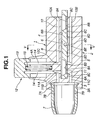
- FIGs. 1 through 11 there are shown the inhalant medicator of the first example and a blister pack 16 applied to the inhalant medicator.
- reference sign 1 denotes an inhalant medicator assembly.
- the inhalant medicator assembly 1 is mainly constructed by a medicator body 2 and an inhalant port 7. As described later, the medicator body 2 is formed therein with a plurality of air passageways, and also serves as a blister pack holder mounting portion for a blister pack 16 which will be fully described later. As best seen in Figs. 3 through 5, as a whole, the medicator body 2 is substantially cylindrical in shape.
- the medicator body 2 is comprised of an upper medicator-body portion 4 having a substantially semi-circular cross section, a lower medicator-body portion 5 having a substantially semi-circular cross section (see Figs. 3 and 5), and a substantially cylindrical joining portion 3 through which the upper and lower medicator-body portions 4 and 5 are formed integral with each other.
- Joining portion 3 has an internal thread portion 3A into which an external thread portion 7A of the inhalant port 7 is screwed.
- Upper and lower medicator-body portions 4 and 5, each having the substantially semi-circular cross section, are constructed in such a manner as to axially extend from the joining portion 3, so that their opposed flat surfaces, namely a ceiling wall surface 6B of a holder mounting groove 6 (described later) and a bottom surface 6C of the holder mounting groove 6, are parallel to each other and spaced apart from each other by a predetermined aperture (see Figs. 3 and 5).
- Medicator body 2 is also formed with the blister pack holder mounting groove 6 defined between upper and lower medicator-body portions 4 and 5. As a whole, the medicator body 2 is substantially cylindrical in shape. As clearly shown in Figs.
- the upper medicator-body portion 4 is formed with a pricking tool guide 4A capable of slidably supporting or guiding a support portion 13 of a pricking tool (pricking means) 12 (described later).
- the holder mounting groove 6 is defined between upper and lower medicator-body portions 4 and 5 by three surfaces, namely an innermost end surface 6A forming part of the joining portion 3, the ceiling wall surface 6B corresponding to the underside of upper medicator-body portion 4, and the bottom surface 6C corresponding to the upside of lower medicator-body portion 5.
- the holder mounting groove 6 opens to three directions, that is, leftwards and rightwards, and in one axial direction of the medicator body.
- the innermost end surface 6A of the groove 6 is formed into a concave circular-arc shape that fits the contour of the outer periphery of a blister pack holder 8 (see Fig. 4).
- the predetermined aperture defined between the ceiling wall surface 6B and the bottom surface 6C is dimensioned to be somewhat greater than the thickness dimension of the holder 8 (see Fig. 1).
- the lower medicator-body portion 5 is formed with a protruded portion 6D extending upwards from a substantially central portion of the bottom surface 6C of holder mounting groove 6, such that the axis of the protruded portion 6D is perpendicular to the bottom surface 6C.
- the protruded portion 6D functions as a center of rotation (or an axis of rotation) of the blister pack holder 8.
- Inhalant port 7 is screwed into the other axial end of medicator body 2, and is substantially cylindrical hollow in shape.
- the top end (the left-hand side axial end of the inhalant medicator assembly 1 shown in Fig. 1) of inhalant port 7 is configured in a manner so as to gradually diametrically small-sized in the other axial direction.
- the root portion of inhalant port 7 is formed nearby the external thread portion 7A with a plurality of radially-extending auxiliary air passageways 7B, 7B, ... (only two auxiliary air passageways 7B and 7B are shown in Fig.
- Each of the auxiliary air passageways 7B serves to avoid difficulty in breathing action by increasing a quantity of air flowing through the inhalant medicator during the breathing action.
- the inhalant port 7 is installed on the other axial end of the medicator body by screwing the external thread portion 7A of inhalant port 7 into the internal thread portion 3A of joining portion 3 of the medicator body.
- the blister pack holder 8 is detachably rotatably mounted into the groove 6 of medicator body 2, so that the disc-shaped holder 8 is easily inserted into and removed from within the groove 6.
- the holder 8 When the innermost end of the guide groove 8E of the holder engages with the protruded portion 6D of the medicator body, the holder 8 is rotatable about the protruded portion 6D. As clearly shown in Figs. 6 and 7, the holder 8 has a substantially disc shape. As can be seen from the top view shown in Fig. 6, the holder 8 is formed on its upside with eight recessed fit portions 8A, 8A, ..., 8A circumferentially spaced apart from each other by 45 degrees and located near its circumference. In the inhalant medicator of the first example, the eight recessed fit portions 8A are configured or formed as eight radially-elongated, substantially semi-cylindrical cavities.
- Eight blistered portions 16B of blister pack 16 are integrally fitted into the respective eight recessed fit portions 8A of holder 8.
- the holder 8 is formed in each of recessed fit portions 8A with an inflow pin insertion hole (a radially inward pin insertion hole) 8B and an outflow pin insertion hole (a radially-outward pin insertion hole) 8C spaced apart from each other in the radial direction of the holder 8 (viewing Fig. 6), so that two pin insertion holes 8B and 8C penetrate the disc-shaped holder 8 in a direction perpendicular to upper and lower surfaces of the holder 8. As viewed from the top view of Fig.
- recessed fit portions 8A eight pairs of radially-aligned inward and outward pin insertion holes (8B, 8C) are also circumferentially spaced apart from each other by 45 degrees.
- the holder 8 is also formed with eight recessed fit portions 8D, 8D, ... , 8D.
- the recessed fit portions 8D are formed as eight small spherical bowl cavities.
- the number of the recessed fit portions 8D is an even number, for easy but reliable engagement between one diametrically-opposed pair (8D, 8D) of the eight recessed fit portions and a pair of spring-loaded balls (9A, 9A) of a positioning mechanism 9 (described later).
- a positioning mechanism (positioning means) 9 is provided between the holder 8 and the blister pack holder mounting portion of the medicator body for positioning one of the medical powder storage chambers of the blister pack installed or held on the holder 8 at a predetermined pricking position.
- a pair of spherical ball portions (9B, 9B) included in the positioning mechanism 9 are easily fitted to one diametrically-opposed pair (8D, 8D) of the eight recessed fit portions.
- Such easy fit between two spherical ball portions (9B, 9B) and diametrically-opposed pair (8D, 8D) ensures easy rotation of the holder 8 about the protruded portion 6D (serving as the axis of rotation of the holder 8) and is produced by proper mechanical snap action during rotary motion of the holder.
- two spherical ball portions (9B, 9B) are comprised of spring-loaded balls included in the positioning mechanism 9 (described later).
- the eight recessed fit portions 8D are located around the center of the holder 8.
- Each of recessed fit portions 8D is located on a straight line including two centers of the associated radially-aligned inward and outward pin insertion holes 8B and 8C.
- the eight recessed fit portions 8D are also circumferentially spaced apart from each other by 45 degrees.
- the holder 8 is also formed on the underside with the guide groove 8E radially extending from the center of rotation of the holder 8.
- the guide groove 8E is formed to guide the protruded portion 6D of the holder mounting groove 6 toward the center of rotation of the holder 8.
- the holder 8 is inserted or mounted into the holder mounting groove 6 in accordance with the following procedures.
- the guide groove 8E is engaged with the protruded portion 6D under a condition where the blister pack 16 is installed on and fitted to the upside of the holder 8. Thereafter, the holder 8 installing thereon the blister pack 16, is inserted into the holder mounting groove 6 of medicator body 2, until the innermost end of the guide groove 8E of the holder reaches the protruded portion 6D of the medicator body.
- a component part denoted by 9 is the positioning mechanism (or positioning means).
- the positioning mechanism 9 includes a pair of spring-loaded ball housing bores (9A, 9A) each closed at one end.
- the bores (9A, 9A) are point-symmetrical with respect to the protruded portion 6D and formed in the bottom surface 6C (lower medicator-body portion 5) of holder mounting groove 6.
- the positioning mechanism 9 also includes two spring-loaded spherical balls (9B, 9B) housed in the respective ball housing bores (9A, 9A) in an unremovable fashion so that the inside diameter of the opening end of each spring-loaded ball housing bore 9A is slightly less than the inside diameter of the other portion of the bore 9A, and two coil springs (9C, 9C), each operably disposed in the ball housing bore 9A in a manner so as to permanently bias the associated ball 9B in a direction that causes a part of the spherical surface of the ball 9B to be slightly protruded from the bottom surface 6C through an opening end of the bore 9A into the groove 6 of medicator body 2.
- the positioning mechanism 9 is comprised of a snap-action mechanism with a pair of spring-loaded balls (9B, 9B).
- the two spring-loaded balls (9B, 9B) can be brought into engagement with the respective recessed fit portions (8D, 8D) of the holder 8.
- one of eight radially-elongated recessed fit portions 8A (that is, one of eight medical powder storage chambers 16D of blister pack 16) is efficiently reliably positioned in a predetermined pricking position of the pricking tool 12 (or in a set position for inhalant medication).
- Reference sign 10 denotes an inflow air passageway through which the atmosphere (outside air) can be introduced into or directed toward within the recessed fit portion 8A of the holder 8.
- the inflow air passageway 10 includes an upper axially-extending air passage 10A which is bored or formed in the upper medicator-body portion 4, and whose one axial end opens at one axial end of the upper medicator-body portion 4 to the atmosphere.
- the inflow air passageway 10 includes a lower axially-extending air passage 10B which is bored or formed in the lower medicator-body portion 5, and whose one axial end opens at one axial end of the lower medicator-body portion 5 to the atmosphere.
- the inflow air passageway 10 also includes a radially-extending pin insertion hole 10C formed in the medicator body 2 so that the pin insertion hole 10C radially extends from the pricking tool guide 4A via the upper medicator-body portion 4 toward the lower medicator-body portion 5.
- the radially-extending pin insertion hole 10C is fluidly communicated with the other axial end of each of the upper and lower axially-extending air passages 10A and 10B.
- the pin insertion hole 10C is designed to communicate with the inflow pin insertion hole 8B of the holder 8, when one of eight recessed fit portions 8A of the holder 8 is positioned in the pricking position.
- reference sign 11 denotes an outflow air passageway through which medical powder stored in the medical powder storage chamber 16D of the blister pack 16 flows into the inhalant port 7.
- the outflow air passageway 11 includes a pin insertion hole 11A, an upper outflow air passage 11B, and a lower outflow air passage 11C.
- the pin insertion hole 11A radially extends in parallel with the pin insertion hole 10C of the inflow air passageway 10.
- the upper outflow air passage 11B axially extends from the upper medicator-body portion 4 via the joining portion 3 toward the inhalant port 7.
- One axial end of the upper outflow air passage 11B is fluidly communicated with the pin insertion hole 11A, whereas the other axial end opens to the interior space of the inhalant port 7.
- a component part denoted by reference sign 12 is the pricking tool used to prick holes in the blister pack 16.
- the pricking tool 12 includes the support portion 13 whose outer periphery is slidably supported or guided by a cylindrical inner peripheral wall of the pricking tool guide 4A, and a pair of parallel pins (14, 14) whose root portions are fixedly connected to the support portion 13, and whose tips are inserted into the respective pin insertion holes 10C and 11A.
- the pair of parallel pins are spaced apart from each other by a predetermined distance smaller than a longitudinal length of each of the blistered portions of the blister pack.
- the pricking tool 12 also includes a return spring 15 operably disposed between the support portion 13 and the upper medicator-body portion 4 for permanently biasing the support portion 13 and the pins (14, 14) toward their initial positions.
- a patient pushes the support portion 13 of pricking tool 12 into the pricking tool guide 4A against the bias of the spring 15, and thus the two pins (14, 14) are deeply inserted into the respective pin insertion holes 10C and 11A.
- the tips of pins (14, 14) penetrate the blister pack 16.
- two inflow holes or two inflow ports (H1, H1) and two outflow holes or two outflow ports (H2, H2) are pricked respectively in the blistered portion 16B of a base panel 16A and a lid panel 16C of blister pack 16 (see Figs. 10 and 11), so that two inflow holes (H1, H1) and two outflow holes (H2, H2) are pricked in a perpendicular to the upper surface of the lid panel of the blister pack, and two inflow holes (H1, H1) and two outflow holes (H2, H2) are spaced apart from each other by a predetermined distance which corresponds to a distance between the downstream end of the inflow air passage and the upstream end of the outflow air passageway.
- eight blistered portions 16B of the base panel 16A define eight medical powder storage chambers 16D in conjunction with the lid panel 16C. After pricking, as soon as the pushing force applied to the support portion 13 is removed, the support portion 13 and the two pins (14, 14) are returned back to their initial positions.
- blister pack 16 is comprised of base panel 16A and lid panel 16C affixed onto the principal surface (or the obverse) of base panel 16A.
- the base panel 16A has a thin-walled disc shape and is made of synthetic resin, aluminum material, or the like.
- the base panel 16A has a plurality of blistered portions 16B, 16B, ..., 16B (in the first example, eight blistered portions) around its entire circumference.
- the lid panel 16C has a thin-walled disc shape and is made of synthetic resin, aluminum material, or the like.
- the blistered portions 16B formed in the base panel 16A are located near the circumference of the base panel 16A, and formed as eight radially-elongated, substantially semi-cylindrical convex portions.
- the eight blistered portions 16B are circumferentially spaced apart from each other by 45 degrees.
- eight medical powder storage chambers 16D are defined between the eight blistered portions 16B of base panel 16A and the lid panel 16C.
- a predetermined amount of medical powder such as granular medicine or powdered medicine is stored in each of the medical powder storage chambers 16D.
- the inhalant medicator of the first example is constructed as previously discussed. Hereinbelow described in detail in reference to Figs. 9 - 11 are the preliminary operation of inhalant medication through which a patient inhales medical powder, and the flow of air and the flow of medical powder during inhalation.
- blister pack holder 8 is removed from the holder mounting groove 6 of medicator body 2.
- the guide groove 8E formed in the underside of the holder and radially outwardly extending from the center of the holder, must be axially aligned with respect to the axis of the medicator body 2 under a condition in which the outermost end of guide groove 8E faces the inhalant port 7.
- the holder 8 can be removed from the medicator body 2 by pulling the holder 8 against the bias produced by the two spring-loaded balls 9B of the positioning mechanism 9.
- blister pack 16 is fitted to and installed on the upside of holder 8, such that eight blistered portions 16B of the blister pack are fitted to respective recessed fit portions 8A of the holder 8.
- the blister pack 16 can be integrally connected to and reliably positioned with respect to the holder 8, and thus the blister pack 16 is rotatable together with the holder 8.
- the holder 8 is mounted into the holder mounting groove 6.
- the guide groove 8E must be aligned with the axis of the medicator body 2 so that the outermost end of the guide groove 8E is directed toward the inhalant port 7, and also the protruded portion 6D must be engaged with the guide groove 8E.
- two opposed inflow holes (H1, H1) communicating inflow air passageway 10 are pricked in the blistered portion 16B of base panel 16A and in the lid panel 16C by means of one of the two pins (14, 14) inserted into the pin insertion hole 10C, and at the same time two opposed outflow holes (H2, H2) communicating outflow air passageway 11 are pricked in the blistered portion 16B of base panel 16A and in the lid panel 16C by means of the other pin 14 inserted into the pin insertion hole 11A.
- the medical powder storage chamber 16D of blister pack 16 is communicated through the inflow holes (H1, H1) with the inflow air passageway 10, and also communicated through the outflow holes (H2, H2) with the outflow air passageway 11.
- air atmosphere
- the air flow introduced via the inflow holes (H1, H1) into the medical powder storage chamber 16D is brought into collision with the inner wall surface of medical powder storage chamber 16D, because the inflow holes (H1, H1) and the outflow holes (H2, H2) are spaced apart from each other in the axial direction of the medicator body (or in the longitudinal direction of the blistered portion of the blister pack) by a distance between the two pin insertion holes 8B and 8C, thereby resulting in turbulent flow within the medical powder storage chamber 16D.
- the medical powder stored in the chamber 16D can be effectively diffused or micronized by means of the turbulent flow.
- the inflow holes (H1, H1) communicating the inflow air passageway 10 and the outflow holes (H2, H2) communicating the outflow air passageway can be formed or pricked in the blister pack by means of two pins (14, 14) fixedly connected to the pricking tool 12, so that the inflow holes (H1, H1) and the outflow holes (H2, H2) are spaced apart from each other by a predetermined distance corresponding to a distance between the axes of two pins (14, 14).
- air flowing via the inflow holes (H1, H1) toward the outflow holes (H2, H2) is not directed straight, but brought into collision with the inner wall of the medical powder storage chamber.
- Turbulent air flow is thus produced within the medical powder storage chamber by the air flow directed from two inflow holes (H1, H1) via the internal space of the medical powder storage chamber to two outflow holes (H2, H2). Therefore, it is possible to effectively diffuse or micronize medical powder stored in the medical powder storage chamber by virtue of the turbulent air flow occurring in the medical powder storage chamber owing to the two inflow holes and two outflow holes pricked in both the base panel and lid panel of the blister pack by the two parallel pins during inhalation treatment of air/medical powder mixture. As a result of this, it is possible to efficiently reliably prescribe a specified amount of medical powder pre-stored in one of storage chambers 16D into lungs of a patient by way of breathing action.
- the holder 8 is formed on its underside with the recessed fit portions 8D, and additionally the positioning mechanism 9 is provided in the holder mounting groove 6 for positioning the medical powder storage chamber 16D of blister pack 16 at the predetermined pricking position (the set position for inhalant medication) by fitting the spring-loaded balls (9B, 9B) to the recessed fit portions (8D, 8D).
- the predetermined pricking position the set position for inhalant medication
- the medicator body 2 is constructed by not only upper and lower medicator-body portions 4 and 5, but also joining portion 3 interconnecting the upper and lower medicator-body portions 4 and 5, and also the holder mounting groove 6 is simply defined between the upper and lower medicator-body portions.
- a holder mounting groove structure is so simple.
- the inhalant medicator is designed to be easily assembled by mounting the disc-shaped blister pack holder 8 into the holder mounting groove 6 being simple in structure, thus reducing the number of parts of the inhalant medicator assembly. This ensures ease of assembly, and also reduces total production costs of the inhalant medicator.
- the disc-shaped holder 8 is formed on its upside with circumferentially equally spaced, radially-elongated eight recessed fit portions 8A (eight substantially semi-cylindrical cavities).
- the holder 8 is formed on its underside with the guide groove 8E which is engageable with the protruded portion 6D of holder mounting groove 6.
- the guide groove 8E permits the protruded portion 6D to be reliably easily guided to the rotation center of the holder 8 (the innermost end of the guide groove 8E). This ensures accurate and easy mounting of the holder 8 on the desired position of the medicator body 2, thus ensuring ease of handling.
- the modified blister pack 31 shown in Figs. 12 - 15 is characterized by a deeply-recessed medical powder collecting portion 34, as viewed from the cross section shown in Fig. 13.
- the blister pack 31 is comprised of base panel 32, medical powder collecting portion 34, lid panel 35, and medical powder storage chamber 36.
- the base panel 32 has a thin-walled disc shape and is made of synthetic resin, aluminum material, or the like.
- the base panel 32 has a plurality of blistered portions 33, 33, ..., 33 (eight blistered portions) around its entire circumference.
- the shape and material of the lid panel 35 of blister pack 31 are identical to those of blister pack 16 applied to the inhalant medicator of the first example.
- the blistered portions 33 are formed as eight radially-elongated, substantially elliptical convex portions.
- Each of the blistered portions 33 includes a radially-inward, shallow pricked portion 33A in which the previously-noted inflow hole H1 is pricked, and a radially-outward, shallow pricked portion 33B in which the previously-noted outflow hole H2 is pricked.
- the medical powder collecting portion 34 is deeply formed or recessed in the base panel 32 midway between the radially-inward, shallow pricked portion 33A and the radially-outward, shallow pricked portion 33B.
- the medical powder collecting portion 34 serves as an air-flow regulation means as described later.
- the medical powder collecting portion 34 of the blistered portion 33 serves as a deeply-recessed medical powder collecting portion kept at a level lower than the shallow pricked portions (33A, 33B).
- a portion denoted by reference sign 36 is the medical powder storage chamber defined between the blistered portion 33 of base panel 32 and the lid panel 35.
- a predetermined amount of medical powder is stored in the medical powder storage chamber 36, such that almost all of the medical powder is collected or pre-stored in the medical powder collecting portion 34.
- the blister pack 31 shown in Figs. 12 - 15 is constructed as previously discussed. Hereinbelow described in detail in reference to Figs.
- Inflow holes (H1, H1) and outflow holes (H2, H2) are pricked in the blistered portion 33 of base panel 32 and in the lid panel 34 of blister pack 31 held at the predetermined pricking position, after a series of preliminary setting operations have been completed.
- air introduced through the inflow air passage 10 via the inflow holes (H1, H1) into the storage chamber 35 functions to fling up and diffuse a part of medical powder located at the top of the medical powder collecting portion 34 (see Fig. 14).
- the upflung and diffused portion of the medical powder collected in the collecting portion 34 is supplied into the outflow holes (H2, H2).
- the medical powder stored in the storage chamber 36 can be gradually reduced.
- air flow passing through the inflow holes (H1, H1) enters the medical powder collecting portion 34, and therefore medical powder collected in the collecting portion 34 is gradually flung up and diffused from the uppermost portion until a lowermost portion of the medical powder stored is flung up, and thus the diffused medical powder is supplied into the outflow holes (H2, H2) little by little.
- the blister pack 31 having the deeply-recessed medical powder collecting portion 34 it is possible to fling up and uniformly diffuse the medical powder stored in the storage chamber 36 little by little. This prevents a large amount of air/medical powder mixture in one breath from being flown into the outflow holes (H2, H2), thus avoiding the outflow holes from being choked up with such a large amount of medical powder flow mass.
- the patient can inhale the medical powder little by little. This prevents the patient from getting a fit of coughing during the inhalant medication, thus ensuring a stable medication during the breathing action.
- FIG. 16 through 19 there is shown another blister pack 51 of the invention.
- the modified blister pack 51 shown in Figs. 18-19 is characterized by a sloped surface 54, as viewed from the cross section shown in Fig. 17.
- the blister pack 51 is comprised of base panel 52, sloped surface 54, lid panel 55, and medical powder storage chamber 56.
- the blistered portion 53 of blister pack 51 is formed with the previously-noted sloped surface 54 such that a side of the outflow holes (H2, H2) penetrating the radially-outward half of the blistered portion of base panel 52 is formed as a shallow portion, whereas a side of the inflow holes (H1, H1) penetrating the radially-inward half of the blistered portion of base panel 52 is formed as a deep portion.
- the base panel 52 has a plurality of blistered portions 53, 53, ..., 53 (eight blistered portions) around its entire circumference.
- the shape and material of the lid panel 55 of blister pack 51 are identical to those of blister pack 16 applied to the inhalant medicator of the first example.
- the blistered portions 53 are formed as eight radially-elongated, substantially elliptical convex portions.
- the radially-elongated outward half of the blistered portion 53 is formed as a comparatively shallow, sloped surface portion 54 (simply, a sloped surface), while the radially-elongated inward half of the blistered portion 53 is formed as a comparatively deep, recessed portion (simply, a deep recess), as viewed from the cross section shown in Fig 19.
- the sloped surface 54 is dimensioned or sloped upwards so that the convexity ratio of the blistered portion 53 radially decreases from the inside to the outside.
- the outflow holes (H2, H2) are pricked in the sloped surface 54, while the inflow holes (H1, H1) are pricked in the deep recess.
- the medical powder storage chamber 56 is defined between the blistered portion 53 of base panel 52 and the lid panel 55. A predetermined amount of medical powder is stored in the medical powder storage chamber 56, such that almost all of the medical powder is mainly stored in the deep recess corresponding to the inflow holes (H1, H1) by way of the sloped surface 54.
- the blister pack 51 shown in Figs. 16-19 is constructed as previously discussed. Hereinbelow described in detail in reference to Figs. 18 and 19 are the flow of air passing through the medical powder storage chamber 56 and the flow of medical powder within the storage chamber 56 during inhalation.
- Inflow holes (H1, H1) and outflow holes (H2, H2) are pricked in the blistered portion 53 of base panel 52 and in the lid panel 54 of blister pack 51 held at the predetermined pricking position, after a series of preliminary setting operations have been completed.
- air introduced through the inflow holes (H1, H1) into the storage chamber 56 is brought into direct-collision with the medical powder pre-stored in the deep recess of blistered portion 53 in which the inflow holes (H1, H1) are pricked.
- the medical powder is diffused within the storage chamber 56 at a breath (see Fig.
- the blister pack 51 having the sloped surface 54 at the outflow side thereof, it is possible to effectively diffuse the medical powder stored in the storage chamber by way of direct collision between the air flow introduced through the inflow holes (H1, H1) into the storage chamber and the medical powder stored.
- the blister pack 51 functions to uniformly disperse the medical powder into the entire air flow, while adequately diffusing the medical powder within the storage chamber 56. That is, the blister pack 51 permits medical powder to be stably supplied or inhaled into the lungs of the patient little by little.
- the inhalant medicator is exemplified in the blister pack having eight blistered portions (or eight medical powder storage chambers), the invention is not limited to the particular embodiments shown and described herein.
- a blister pack having two or more and seven or less blistered portions, or a blister pack having nine or more blistered portions may be used in the inhalant medication.
- the number of the recessed fit portions (8A; 80A) of holder (8; 80), the number of the pin insertion hole pairs (8B, 8C), and the number of small recessed fit portions 8D must be set to be identical to the number of the blistered portions.
Landscapes
- Health & Medical Sciences (AREA)
- Engineering & Computer Science (AREA)
- Animal Behavior & Ethology (AREA)
- Anesthesiology (AREA)
- Biomedical Technology (AREA)
- Heart & Thoracic Surgery (AREA)
- Hematology (AREA)
- Life Sciences & Earth Sciences (AREA)
- General Health & Medical Sciences (AREA)
- Public Health (AREA)
- Veterinary Medicine (AREA)
- Pulmonology (AREA)
- Bioinformatics & Cheminformatics (AREA)
- Medical Preparation Storing Or Oral Administration Devices (AREA)
- Medicinal Preparation (AREA)
Abstract
Description
- The present invention relates to a blister pack suitable for an inhalant medicator suitable to prescribe granular or powdered medicines toward within lungs of a patient by way of breathing action of the patient.
- Generally, there are two medications of prescribing medical powder toward within lungs of an asthmatic patient, that is, one being a medication that a medicine is inhaled by way of a liquid aerosol atomizer, and the other being an inhalation treatment by way of which granular or powdered medicines (which will be hereinafter referred to as "medical powder") encapsulated in a capsule or stored in a medical powder storage chamber are inhaled.
- Of these medications for an asthmatic patient, an inhalant medicator used for an inhalation treatment where a dose of medical powder is inhaled, is generally constructed by a medicator body including a capsule housing chamber (or a medical powder storage chamber) at one axial end and equipped at the other axial end with an inhalant port through which the medical powder is inhaled, an air passageway communicating the inhalant port with the atmosphere via the capsule housing chamber, and a pricking tool which provided for pricking holes in the capsule accommodated in the capsule housing chamber.
- In recent years, there have been proposed and developed various inhalant medicators utilizing a blister pack having a set of blisters (a plurality of blistered medical powder storage chambers) spaced apart from each other in the circumferential direction, for inhalant medication. Such inhalant medicators have been disclosed in Japanese Patent Provisional Publication Nos. 59-88158 and 62-41668. The inhalant medicator as disclosed in the Japanese Patent Provisional Publication Nos. 59-88158 and 62-41668, includes a blister pack holder which holds a blister pack having a plurality of blisters circumferentially spaced apart from each other. The blister pack holder is rotatably mounted to a medicator body. Also, the blister pack installed on the holder consists of a base panel formed with a large number of blistered portions, a lid panel affixed onto the principal surface of the base panel and defining a plurality of medical powder storage chambers by hermetically covering the blistered portions of the base panel. A dose of medical powder is stored in each of the medical powder storage chambers. In order to prescribe or administer the medical powder toward within lungs of a patient by way of breathing action, first, the blister pack is installed on the pack holder of the inhalant medicator. Second, holes needed to intercommunicate the atmospheric side and the inhalant port via the internal space of the medical powder storage chamber are pricked by means of a single plunger having a needle-shaped pricking tip. Under these conditions, when the patient draws his or her breath while taking the inhalant port in his or her mouse, air flow directed from the pricked holes through the medical powder storage chamber into the inhalant port enables medical powder stored in the medical powder storage chamber to be carried into the inhalant port. In this manner, medical powder stored in the storage chamber can be inhaled through the inhalant port into lungs of the patient. In order to continuously perform inhalant medication, the blister pack is rotated by a predetermined angle together with the blister pack holder, and then the next medical powder storage chamber of the same blister pack is set at the pricking position. Thereafter, in the same manner described previously, a series of inhalant medication procedures are made. Thus, it is possible to consecutively dose a patient with a specified amount of medical powder by rotation of the blister pack holder without exchanging a capsule.
- However, in the inhalant medicators as disclosed in the Japanese Patent Provisional Publication Nos. 59-88158 and 62-41668, in order to prick holes in the medical powder storage chamber of the blister pack, a single needle-shaped plunger is used as the pricking tool. Thus, two holes, penetrating the medical powder storage chamber aligned to each other in a direction perpendicular to upper and lower surfaces of the blister pack, are pricked or pierced in one blistered portion of the blister pack. Air introduced into the medical powder storage chamber (the blistered portion) flows straight through the medical powder storage chamber from one (the inflow side) of the two pricked holes to the other (the outflow side). Actually, various sorts of medical powder having different characteristics or properties, such as a condensation property, a particle size (fine powder, granule, or the like) are used.
-
GB 2 129 691 A discloses a device for administering medicaments to patients comprises a housing containing a cylindrical chamber. A support is arranged inside the chamber to support a carrier, such as a blister pack. The blister pack has a plurality of containers or blisters arranged in a circle. When a blister pack is located on the support its blisters are located in holes in the support member. A plunger is arranged to enter the chamber through a hole to engage and open a blister registered with it. When the blister is opened, medicament can be withdrawn by a patient inhaling through a mouthpiece. An external member is provided to rotate the support member to register the blister with the plunger in turn. Air can conveniently enter the chamber through a hole in a cover which is removable to permit blister packs to be loaded into the chamber onto the support member. - In the previously-described inhalant medicator with a single needle-shaped plunger, it is impossible to adequately diffuse medical powder in a medical powder storage chamber of a blister pack by way of such straight air flow (directed from one pricked hole to the other) in which there is less turbulence and thus the air stream direction is almost same, and which has a substantially constant flow velocity. Thus, some medical powder may be undesirably left in the medical powder storage chamber after prescribing the medical powder toward within lungs of a patient by breathing action. As a result of this, the patient cannot inhale a specified amount of medical powder into the lungs, thus lowering medical benefits of powdered or granular medicines.
- It is the object of the invention to provide a blister pack suitable for an inhalant medicator, which enhances a medication efficiency, effectively diffusing medical powder stored in a medical powder storage chamber of the blister pack depending on characteristics or properties of the medical powder, such as a strong condensation property, and a particle size.
- This object is achieved by a blister pack according to
claim - According to the invention, a blister pack for an inhalant medicator comprises a base panel having a blistered portion, a lid panel affixed onto an obverse of the base panel to define a medical powder storage chamber by hermetically covering the blistered portion of the base panel, the blistered portion comprising a pair of shallow pricked portions in which inflow and outflow holes are pricked during a preliminary operation of inhalant medication; and a medical powder collecting portion deeply recessed between the shallow pricked portions to pre-store medical powder therein.
- According to the invention, a blister pack for an inhalant medicator comprises a base panel having a blistered portion in which inflow and outflow holes are pricked during a preliminary operation of inhalant medication, a lid panel affixed onto an obverse of the base panel to define a medical powder storage chamber by hermetically covering the blistered portion of the base panel, and the blistered portion comprising a sloped surface which defines a shallow portion at a side of the outflow hole and defines a deep portion at a side of the inflow hole.
- Other features of this invention will become understood from the following description with reference to the accompanying drawings.
-
- Fig. 1 is a longitudinal cross-sectional view illustrating one example of an inhalant medicator.
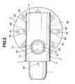
- Fig. 2 is a plan view illustrating the inhalant medicator shown in Fig. 1.
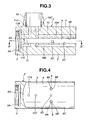
- Fig. 3 is a longitudinal cross-sectional view illustrating details of a medicator body of the inhalant medicator shown in Fig. 1.
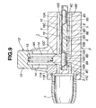
- Fig. 4 is a longitudinal cross-sectional view of the medicator body, taken along the line IV - IV shown in Fig. 3.
- Fig. 5 is a lateral cross-sectional view illustrating the medicator body and a positioning mechanism, taken along the line V - V of Fig. 1.
- Fig. 6 is a top view illustrating a blister pack holder (8) mounted on the medicator body of the inhalant medicator shown in Fig. 1.
- Fig. 7 is a bottom view illustrating the blister pack holder (8) shown in Fig. 6.
- Fig. 8 is a perspective view of a blister pack (16) to be installed on the holder of Fig. 6, as viewed from its bottom side (its base panel side).
- Fig. 9 is a longitudinal cross-sectional view illustrating the inhalant medicator in a state where the blister pack is installed on the holder of Fig. 6 and then the holder is mounted in a holder mounting groove formed in the medicator body of the inhalant medicator shown in Fig. 1.
- Fig. 10 is a longitudinal cross-sectional view illustrating the inhalant medicator in a state where medical powder stored in the storage chamber of the blister pack (16) installed on the holder of Fig. 6 is inhaled.
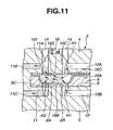
- Fig. 11 is a partly enlarged longitudinal cross-sectional view showing air flow and medical powder flow in the medical powder storage chamber (16D) of the blister pack (16) installed on the holder of Fig. 6.
- Fig. 12 is a perspective view of a blister pack (31) of the invention, as viewed from its bottom side (its base panel side).
- Fig. 13 is a partly enlarged longitudinal cross-sectional view showing a blistered portion (33), a medical-powder storage chamber (36), and a medical powder collecting portion (34).
- Fig. 14 is a partly enlarged longitudinal cross-sectional view showing air flow and medical powder flow in the medical powder storage chamber of the blister pack of the invention (31) of Fig. 12, during initial inhalation action.
- Fig. 15 is a partly enlarged longitudinal cross-sectional view showing air flow and medical powder flow in the medical powder storage chamber of the blister pack of the invention (31) in the middle of the inhalation action.
- Fig. 16 is a perspective view of another modified blister pack (51) of the invention, as viewed from its bottom side (its base panel side).
- Fig. 17 is a partly enlarged longitudinal cross-sectional view showing a blistered portion (53), a medical-powder storage chamber (56), and a sloped surface (54).
- Fig. 18 is a partly enlarged longitudinal cross-sectional view showing air flow and medical powder flow in the medical powder storage chamber of the blister pack (51) of Fig. 16, during initial inhalation action.
- Fig. 19 is a partly enlarged longitudinal cross-sectional view showing air flow and medical powder flow in the medical powder storage chamber of the blister pack (51) in the middle of the inhalation action.
- Referring now to the drawings, particularly to Figs. 1 through 11, there are shown the inhalant medicator of the first example and a
blister pack 16 applied to the inhalant medicator. In Figs. 1, 2, 9 and 10,reference sign 1 denotes an inhalant medicator assembly. Theinhalant medicator assembly 1 is mainly constructed by amedicator body 2 and aninhalant port 7. As described later, themedicator body 2 is formed therein with a plurality of air passageways, and also serves as a blister pack holder mounting portion for ablister pack 16 which will be fully described later. As best seen in Figs. 3 through 5, as a whole, themedicator body 2 is substantially cylindrical in shape. To be exact, themedicator body 2 is comprised of an upper medicator-body portion 4 having a substantially semi-circular cross section, a lower medicator-body portion 5 having a substantially semi-circular cross section (see Figs. 3 and 5), and a substantially cylindrical joiningportion 3 through which the upper and lower medicator-body portions portion 3 has aninternal thread portion 3A into which anexternal thread portion 7A of theinhalant port 7 is screwed. Upper and lower medicator-body portions portion 3, so that their opposed flat surfaces, namely aceiling wall surface 6B of a holder mounting groove 6 (described later) and abottom surface 6C of theholder mounting groove 6, are parallel to each other and spaced apart from each other by a predetermined aperture (see Figs. 3 and 5).Medicator body 2 is also formed with the blister packholder mounting groove 6 defined between upper and lower medicator-body portions medicator body 2 is substantially cylindrical in shape. As clearly shown in Figs. 1, 3 and 5, the upper medicator-body portion 4 is formed with apricking tool guide 4A capable of slidably supporting or guiding asupport portion 13 of a pricking tool (pricking means) 12 (described later). Theholder mounting groove 6 is defined between upper and lower medicator-body portions innermost end surface 6A forming part of the joiningportion 3, theceiling wall surface 6B corresponding to the underside of upper medicator-body portion 4, and thebottom surface 6C corresponding to the upside of lower medicator-body portion 5. As viewed from the axial direction of theinhalant port 7, theholder mounting groove 6 opens to three directions, that is, leftwards and rightwards, and in one axial direction of the medicator body. Theinnermost end surface 6A of thegroove 6 is formed into a concave circular-arc shape that fits the contour of the outer periphery of a blister pack holder 8 (see Fig. 4). The predetermined aperture defined between theceiling wall surface 6B and thebottom surface 6C is dimensioned to be somewhat greater than the thickness dimension of the holder 8 (see Fig. 1). The lower medicator-body portion 5 is formed with a protrudedportion 6D extending upwards from a substantially central portion of thebottom surface 6C ofholder mounting groove 6, such that the axis of the protrudedportion 6D is perpendicular to thebottom surface 6C. The protrudedportion 6D functions as a center of rotation (or an axis of rotation) of theblister pack holder 8. The protrudedportion 6D is engaged with aguide groove 8E formed in theholder 8, when mounting theholder 8 into thegroove 6.Inhalant port 7 is screwed into the other axial end ofmedicator body 2, and is substantially cylindrical hollow in shape. The top end (the left-hand side axial end of theinhalant medicator assembly 1 shown in Fig. 1) ofinhalant port 7 is configured in a manner so as to gradually diametrically small-sized in the other axial direction. As shown in Fig. 1, the root portion ofinhalant port 7 is formed nearby theexternal thread portion 7A with a plurality of radially-extendingauxiliary air passageways auxiliary air passageways auxiliary air passageways 7B serves to avoid difficulty in breathing action by increasing a quantity of air flowing through the inhalant medicator during the breathing action. As can be appreciated from the cross section shown in Fig. 1, theinhalant port 7 is installed on the other axial end of the medicator body by screwing theexternal thread portion 7A ofinhalant port 7 into theinternal thread portion 3A of joiningportion 3 of the medicator body. On the other hand, theblister pack holder 8 is detachably rotatably mounted into thegroove 6 ofmedicator body 2, so that the disc-shapedholder 8 is easily inserted into and removed from within thegroove 6. When the innermost end of theguide groove 8E of the holder engages with the protrudedportion 6D of the medicator body, theholder 8 is rotatable about the protrudedportion 6D. As clearly shown in Figs. 6 and 7, theholder 8 has a substantially disc shape. As can be seen from the top view shown in Fig. 6, theholder 8 is formed on its upside with eight recessedfit portions fit portions 8A are configured or formed as eight radially-elongated, substantially semi-cylindrical cavities. Eightblistered portions 16B of blister pack 16 (described later) are integrally fitted into the respective eight recessedfit portions 8A ofholder 8. Theholder 8 is formed in each of recessedfit portions 8A with an inflow pin insertion hole (a radially inward pin insertion hole) 8B and an outflow pin insertion hole (a radially-outward pin insertion hole) 8C spaced apart from each other in the radial direction of the holder 8 (viewing Fig. 6), so that twopin insertion holes holder 8 in a direction perpendicular to upper and lower surfaces of theholder 8. As viewed from the top view of Fig. 6 and from the bottom view of Fig 8, and as can be appreciated from the circumferentially-spaced layout of eight radially-elongated recessedfit portions 8A, eight pairs of radially-aligned inward and outward pin insertion holes (8B, 8C) are also circumferentially spaced apart from each other by 45 degrees. As viewed from the bottom view shown in Fig. 7, theholder 8 is also formed with eight recessedfit portions fit portions 8D are formed as eight small spherical bowl cavities. As shown, the number of the recessedfit portions 8D is an even number, for easy but reliable engagement between one diametrically-opposed pair (8D, 8D) of the eight recessed fit portions and a pair of spring-loaded balls (9A, 9A) of a positioning mechanism 9 (described later). As fully described later, a positioning mechanism (positioning means) 9 is provided between theholder 8 and the blister pack holder mounting portion of the medicator body for positioning one of the medical powder storage chambers of the blister pack installed or held on theholder 8 at a predetermined pricking position. A pair of spherical ball portions (9B, 9B) included in thepositioning mechanism 9 are easily fitted to one diametrically-opposed pair (8D, 8D) of the eight recessed fit portions. Such easy fit between two spherical ball portions (9B, 9B) and diametrically-opposed pair (8D, 8D) ensures easy rotation of theholder 8 about the protrudedportion 6D (serving as the axis of rotation of the holder 8) and is produced by proper mechanical snap action during rotary motion of the holder. As shown, two spherical ball portions (9B, 9B) are comprised of spring-loaded balls included in the positioning mechanism 9 (described later). The eight recessedfit portions 8D (eight small spherical bowl cavities) are located around the center of theholder 8. Each of recessedfit portions 8D is located on a straight line including two centers of the associated radially-aligned inward and outwardpin insertion holes fit portions 8D are also circumferentially spaced apart from each other by 45 degrees. Theholder 8 is also formed on the underside with theguide groove 8E radially extending from the center of rotation of theholder 8. Theguide groove 8E is formed to guide the protrudedportion 6D of theholder mounting groove 6 toward the center of rotation of theholder 8. Theholder 8 is inserted or mounted into theholder mounting groove 6 in accordance with the following procedures. First, theguide groove 8E is engaged with the protrudedportion 6D under a condition where theblister pack 16 is installed on and fitted to the upside of theholder 8. Thereafter, theholder 8 installing thereon theblister pack 16, is inserted into theholder mounting groove 6 ofmedicator body 2, until the innermost end of theguide groove 8E of the holder reaches the protrudedportion 6D of the medicator body. As best seen in Figs. 4 and 5, a component part denoted by 9 is the positioning mechanism (or positioning means). Thepositioning mechanism 9 includes a pair of spring-loaded ball housing bores (9A, 9A) each closed at one end. The bores (9A, 9A) are point-symmetrical with respect to the protrudedportion 6D and formed in thebottom surface 6C (lower medicator-body portion 5) ofholder mounting groove 6. Thepositioning mechanism 9 also includes two spring-loaded spherical balls (9B, 9B) housed in the respective ball housing bores (9A, 9A) in an unremovable fashion so that the inside diameter of the opening end of each spring-loadedball housing bore 9A is slightly less than the inside diameter of the other portion of thebore 9A, and two coil springs (9C, 9C), each operably disposed in the ball housing bore 9A in a manner so as to permanently bias the associatedball 9B in a direction that causes a part of the spherical surface of theball 9B to be slightly protruded from thebottom surface 6C through an opening end of thebore 9A into thegroove 6 ofmedicator body 2. As shown, thepositioning mechanism 9 is comprised of a snap-action mechanism with a pair of spring-loaded balls (9B, 9B). With the previously-noted arrangement of thepositioning mechanism 9, when theholder 8 is rotated under a condition where theholder 8 has been mounted into thegroove 6 ofmedicator body 2, the two spring-loaded balls (9B, 9B) can be brought into engagement with the respective recessed fit portions (8D, 8D) of theholder 8. By way of the engagement between the two spring-loaded balls (9B, 9B) and the recessed fit portions (8D, 8D) with the rotary motion of theholder 8, one of eight radially-elongated recessedfit portions 8A (that is, one of eight medicalpowder storage chambers 16D of blister pack 16) is efficiently reliably positioned in a predetermined pricking position of the pricking tool 12 (or in a set position for inhalant medication).Reference sign 10 denotes an inflow air passageway through which the atmosphere (outside air) can be introduced into or directed toward within the recessedfit portion 8A of theholder 8. Theinflow air passageway 10 includes an upper axially-extendingair passage 10A which is bored or formed in the upper medicator-body portion 4, and whose one axial end opens at one axial end of the upper medicator-body portion 4 to the atmosphere. In a similar manner, theinflow air passageway 10 includes a lower axially-extendingair passage 10B which is bored or formed in the lower medicator-body portion 5, and whose one axial end opens at one axial end of the lower medicator-body portion 5 to the atmosphere. Theinflow air passageway 10 also includes a radially-extendingpin insertion hole 10C formed in themedicator body 2 so that thepin insertion hole 10C radially extends from thepricking tool guide 4A via the upper medicator-body portion 4 toward the lower medicator-body portion 5. The radially-extendingpin insertion hole 10C is fluidly communicated with the other axial end of each of the upper and lower axially-extendingair passages pin insertion hole 10C is designed to communicate with the inflowpin insertion hole 8B of theholder 8, when one of eight recessedfit portions 8A of theholder 8 is positioned in the pricking position. On the other hand,reference sign 11 denotes an outflow air passageway through which medical powder stored in the medicalpowder storage chamber 16D of theblister pack 16 flows into theinhalant port 7. Theoutflow air passageway 11 includes apin insertion hole 11A, an upperoutflow air passage 11B, and a loweroutflow air passage 11C. Thepin insertion hole 11A radially extends in parallel with thepin insertion hole 10C of theinflow air passageway 10. The upperoutflow air passage 11B axially extends from the upper medicator-body portion 4 via the joiningportion 3 toward theinhalant port 7. One axial end of the upperoutflow air passage 11B is fluidly communicated with thepin insertion hole 11A, whereas the other axial end opens to the interior space of theinhalant port 7. In a similar manner, one axial end of the loweroutflow air passage 11C is fluidly communicated with thepin insertion hole 11A, whereas the other axial end opens to the interior space of theinhalant port 7. In Fig. 1, a component part denoted byreference sign 12 is the pricking tool used to prick holes in theblister pack 16. As shown in Fig. 1, the prickingtool 12 includes thesupport portion 13 whose outer periphery is slidably supported or guided by a cylindrical inner peripheral wall of thepricking tool guide 4A, and a pair of parallel pins (14, 14) whose root portions are fixedly connected to thesupport portion 13, and whose tips are inserted into the respectivepin insertion holes pricking tool 12 also includes areturn spring 15 operably disposed between thesupport portion 13 and the upper medicator-body portion 4 for permanently biasing thesupport portion 13 and the pins (14, 14) toward their initial positions. When the pricking action is performed, a patient pushes thesupport portion 13 of prickingtool 12 into thepricking tool guide 4A against the bias of thespring 15, and thus the two pins (14, 14) are deeply inserted into the respectivepin insertion holes blister pack 16. As a result of this, two inflow holes or two inflow ports (H1, H1) and two outflow holes or two outflow ports (H2, H2) are pricked respectively in the blisteredportion 16B of abase panel 16A and alid panel 16C of blister pack 16 (see Figs. 10 and 11), so that two inflow holes (H1, H1) and two outflow holes (H2, H2) are pricked in a perpendicular to the upper surface of the lid panel of the blister pack, and two inflow holes (H1, H1) and two outflow holes (H2, H2) are spaced apart from each other by a predetermined distance which corresponds to a distance between the downstream end of the inflow air passage and the upstream end of the outflow air passageway. As detailed hereunder, eight blisteredportions 16B of thebase panel 16A define eight medicalpowder storage chambers 16D in conjunction with thelid panel 16C. After pricking, as soon as the pushing force applied to thesupport portion 13 is removed, thesupport portion 13 and the two pins (14, 14) are returned back to their initial positions. - Referring now to Figs. 8 and 9, there is shown the detailed structure of the
blister pack 16 applied to the inhalant medicator of the first example. As shown in Figs. 8 and 9,blister pack 16 is comprised ofbase panel 16A andlid panel 16C affixed onto the principal surface (or the obverse) ofbase panel 16A. Thebase panel 16A has a thin-walled disc shape and is made of synthetic resin, aluminum material, or the like. As best seen in Fig. 8, thebase panel 16A has a plurality of blisteredportions lid panel 16C has a thin-walled disc shape and is made of synthetic resin, aluminum material, or the like. Theblistered portions 16B formed in thebase panel 16A are located near the circumference of thebase panel 16A, and formed as eight radially-elongated, substantially semi-cylindrical convex portions. The eight blisteredportions 16B are circumferentially spaced apart from each other by 45 degrees. By hermetically covering or closing thebase panel 16A having eight blisteredportions 16B by thelid panel 16C, eight medicalpowder storage chambers 16D are defined between the eight blisteredportions 16B ofbase panel 16A and thelid panel 16C. Actually, a predetermined amount of medical powder, such as granular medicine or powdered medicine is stored in each of the medicalpowder storage chambers 16D. - The inhalant medicator of the first example is constructed as previously discussed. Hereinbelow described in detail in reference to Figs. 9 - 11 are the preliminary operation of inhalant medication through which a patient inhales medical powder, and the flow of air and the flow of medical powder during inhalation.
- First of all,
blister pack holder 8 is removed from theholder mounting groove 6 ofmedicator body 2. During removal of theholder 8, theguide groove 8E, formed in the underside of the holder and radially outwardly extending from the center of the holder, must be axially aligned with respect to the axis of themedicator body 2 under a condition in which the outermost end ofguide groove 8E faces theinhalant port 7. Then, theholder 8 can be removed from themedicator body 2 by pulling theholder 8 against the bias produced by the two spring-loadedballs 9B of thepositioning mechanism 9. Then,blister pack 16 is fitted to and installed on the upside ofholder 8, such that eight blisteredportions 16B of the blister pack are fitted to respective recessedfit portions 8A of theholder 8. At this time, by fitting theblistered portions 16B (the medicalpowder storage chambers 16D) to the respective recessedfit portions 8A, theblister pack 16 can be integrally connected to and reliably positioned with respect to theholder 8, and thus theblister pack 16 is rotatable together with theholder 8. After theblister pack 16 has been installed on theholder 8, theholder 8 is mounted into theholder mounting groove 6. In this case, theguide groove 8E must be aligned with the axis of themedicator body 2 so that the outermost end of theguide groove 8E is directed toward theinhalant port 7, and also the protrudedportion 6D must be engaged with theguide groove 8E. In this manner, after theholder 8 has been completely pushed into theholder mounting groove 6 until the innermost end of theguide groove 8E engages with the protrudedportion 6D, two balls (9B, 9B) of thepositioning mechanism 9 are engaged with the two diametrically-opposed, small recessedfit portions 8D of theholder 8 by rotating theholder 8 in an arbitrary direction. By way of a series of preliminary setting operations as discussed above, as shown in Fig. 9, it is possible to accurately position one of the medicalpowder storage chambers 16D ofblister pack 16 at the predetermined pricking position (the set position for inhalant medication). - Hereunder described in detail is the actual operation of inhalant medication made by virtue of breathing action of a patient. First of all, in order to prick holes in the
blister pack 16 held at the predetermined pricking position, thesupport portion 13 of prickingtool 12 is pushed or depressed. As shown in Figs. 10 and 11, two opposed inflow holes (H1, H1) communicatinginflow air passageway 10 are pricked in the blisteredportion 16B ofbase panel 16A and in thelid panel 16C by means of one of the two pins (14, 14) inserted into thepin insertion hole 10C, and at the same time two opposed outflow holes (H2, H2) communicatingoutflow air passageway 11 are pricked in the blisteredportion 16B ofbase panel 16A and in thelid panel 16C by means of theother pin 14 inserted into thepin insertion hole 11A. As a result, the medicalpowder storage chamber 16D ofblister pack 16 is communicated through the inflow holes (H1, H1) with theinflow air passageway 10, and also communicated through the outflow holes (H2, H2) with theoutflow air passageway 11. Under these conditions , when the patient draws his or her breath while taking theinhalant port 7 in his or her mouse, air (atmosphere) passes through theinflow air passageway 10 via the two inflow holes (H1, H1) and then flows into the medicalpowder storage chamber 16D. At this time, the air flow introduced via the inflow holes (H1, H1) into the medicalpowder storage chamber 16D is brought into collision with the inner wall surface of medicalpowder storage chamber 16D, because the inflow holes (H1, H1) and the outflow holes (H2, H2) are spaced apart from each other in the axial direction of the medicator body (or in the longitudinal direction of the blistered portion of the blister pack) by a distance between the twopin insertion holes powder storage chamber 16D. Thus, the medical powder stored in thechamber 16D can be effectively diffused or micronized by means of the turbulent flow. As a consequence, it is possible to effectively flow out almost all of the medical powder pre-stored in thestorage chamber 16D through the outflow holes (H2, H2) and theoutflow air passageway 11 into theinhalant port 7 by virtue of the turbulent air flow. As discussed above, during breathing action, the patient can inhale a specified amount of medical powder via his or her oral cavity and trachea into lungs with the aid of the turbulent air flow. In this manner, the first inhalant medication can be completed. Subsequently to the above, when the second inhalant medication is needed, theholder 8 is first rotated from the current angular position by 45 degrees. The next diametrically-opposed recessedfit portions 8D ofholder 8 are thus engaged with the two spring-loadedballs 9B ofpositioning mechanism 9. After this, through the previously-noted pricking operation and inhaling operation, it is possible to inhale medical powder pre-stored in the other medicalpowder storage chamber 16D. In this manner, eight inhalant medications in total can be continuously made. After the eight inhalant medications in total have been made, theholder 8 is removed from themedicator body 2, and then the old blister pack is replaced with a new blister pack for the next inhalation medication. - As set forth above, according to the inhalant medicator of the first example, the inflow holes (H1, H1) communicating the
inflow air passageway 10 and the outflow holes (H2, H2) communicating the outflow air passageway can be formed or pricked in the blister pack by means of two pins (14, 14) fixedly connected to thepricking tool 12, so that the inflow holes (H1, H1) and the outflow holes (H2, H2) are spaced apart from each other by a predetermined distance corresponding to a distance between the axes of two pins (14, 14). As a result of this, air flowing via the inflow holes (H1, H1) toward the outflow holes (H2, H2) is not directed straight, but brought into collision with the inner wall of the medical powder storage chamber. Turbulent air flow is thus produced within the medical powder storage chamber by the air flow directed from two inflow holes (H1, H1) via the internal space of the medical powder storage chamber to two outflow holes (H2, H2). Therefore, it is possible to effectively diffuse or micronize medical powder stored in the medical powder storage chamber by virtue of the turbulent air flow occurring in the medical powder storage chamber owing to the two inflow holes and two outflow holes pricked in both the base panel and lid panel of the blister pack by the two parallel pins during inhalation treatment of air/medical powder mixture. As a result of this, it is possible to efficiently reliably prescribe a specified amount of medical powder pre-stored in one ofstorage chambers 16D into lungs of a patient by way of breathing action. This enhances medical benefits of the medical powder, thereby enhancing the reliability of the inhalant medicator. Furthermore, theholder 8 is formed on its underside with the recessedfit portions 8D, and additionally thepositioning mechanism 9 is provided in theholder mounting groove 6 for positioning the medicalpowder storage chamber 16D ofblister pack 16 at the predetermined pricking position (the set position for inhalant medication) by fitting the spring-loaded balls (9B, 9B) to the recessed fit portions (8D, 8D). Thus, it is possible to easily accurately position the medicalpowder storage chamber 16D ofblister pack 16 at the predetermined pricking position. In other words, it is possible to accurately prick holes (H1, H1, H2, H2) in the blistered portion ofbase panel 16A ofblister pack 16 and in thelid panel 16C, thus ensuring easy handling of the inhalant medicator. Moreover, in theinhalant medicator assembly 1 of the first example, themedicator body 2 is constructed by not only upper and lower medicator-body portions portion 3 interconnecting the upper and lower medicator-body portions holder mounting groove 6 is simply defined between the upper and lower medicator-body portions. Such a holder mounting groove structure is so simple. The inhalant medicator is designed to be easily assembled by mounting the disc-shapedblister pack holder 8 into theholder mounting groove 6 being simple in structure, thus reducing the number of parts of the inhalant medicator assembly. This ensures ease of assembly, and also reduces total production costs of the inhalant medicator. Additionally, the disc-shapedholder 8 is formed on its upside with circumferentially equally spaced, radially-elongated eight recessedfit portions 8A (eight substantially semi-cylindrical cavities). Thus, it is possible to accurately easily position theblister pack 16 on theholder 8 by fitting theblistered portions 16B to the respective recessedfit portions 8A, thus allowing theblister pack 16 to integrally rotate together with theholder 8. This ensures ease of handling. In addition to the above, theholder 8 is formed on its underside with theguide groove 8E which is engageable with the protrudedportion 6D ofholder mounting groove 6. Theguide groove 8E permits the protrudedportion 6D to be reliably easily guided to the rotation center of the holder 8 (the innermost end of theguide groove 8E). This ensures accurate and easy mounting of theholder 8 on the desired position of themedicator body 2, thus ensuring ease of handling. - Referring now to Figs. 12 through 15, there is shown the
blister pack 31 of the invention. As detailed hereunder, the modifiedblister pack 31 shown in Figs. 12 - 15 is characterized by a deeply-recessed medicalpowder collecting portion 34, as viewed from the cross section shown in Fig. 13. Theblister pack 31 is comprised ofbase panel 32, medicalpowder collecting portion 34,lid panel 35, and medicalpowder storage chamber 36. Thebase panel 32 has a thin-walled disc shape and is made of synthetic resin, aluminum material, or the like. As best seen in Fig. 12, thebase panel 32 has a plurality of blisteredportions lid panel 35 ofblister pack 31 are identical to those ofblister pack 16 applied to the inhalant medicator of the first example. - As best seen in Fig. 13, the
blistered portions 33 are formed as eight radially-elongated, substantially elliptical convex portions. Each of the blisteredportions 33 includes a radially-inward, shallow prickedportion 33A in which the previously-noted inflow hole H1 is pricked, and a radially-outward, shallow prickedportion 33B in which the previously-noted outflow hole H2 is pricked. The medicalpowder collecting portion 34 is deeply formed or recessed in thebase panel 32 midway between the radially-inward, shallow prickedportion 33A and the radially-outward, shallow prickedportion 33B. The medicalpowder collecting portion 34 serves as an air-flow regulation means as described later. When theblister pack 31 is installed on the blister pack holder, the medicalpowder collecting portion 34 of the blisteredportion 33 serves as a deeply-recessed medical powder collecting portion kept at a level lower than the shallow pricked portions (33A, 33B). A portion denoted byreference sign 36 is the medical powder storage chamber defined between the blisteredportion 33 ofbase panel 32 and thelid panel 35. A predetermined amount of medical powder is stored in the medicalpowder storage chamber 36, such that almost all of the medical powder is collected or pre-stored in the medicalpowder collecting portion 34. Theblister pack 31 shown in Figs. 12 - 15 is constructed as previously discussed. Hereinbelow described in detail in reference to Figs. 14 and 15 are the flow of air passing through the medicalpowder storage chamber 36 and the flow of medical powder within thestorage chamber 36 during inhalation. Inflow holes (H1, H1) and outflow holes (H2, H2) are pricked in the blisteredportion 33 ofbase panel 32 and in thelid panel 34 ofblister pack 31 held at the predetermined pricking position, after a series of preliminary setting operations have been completed. Under these conditions, when the patient draws his or her breath while taking theinhalant port 7 in his or her mouse, at the initial stage of the inhaling action, air introduced through theinflow air passage 10 via the inflow holes (H1, H1) into thestorage chamber 35, functions to fling up and diffuse a part of medical powder located at the top of the medical powder collecting portion 34 (see Fig. 14). The upflung and diffused portion of the medical powder collected in the collectingportion 34 is supplied into the outflow holes (H2, H2). When several times of inhaling actions are repeated, the medical powder stored in thestorage chamber 36 can be gradually reduced. At this time, as clearly shown in Fig. 15, air flow passing through the inflow holes (H1, H1) enters the medicalpowder collecting portion 34, and therefore medical powder collected in the collectingportion 34 is gradually flung up and diffused from the uppermost portion until a lowermost portion of the medical powder stored is flung up, and thus the diffused medical powder is supplied into the outflow holes (H2, H2) little by little. As discussed above, according to the structure of theblister pack 31 having the deeply-recessed medicalpowder collecting portion 34, it is possible to fling up and uniformly diffuse the medical powder stored in thestorage chamber 36 little by little. This prevents a large amount of air/medical powder mixture in one breath from being flown into the outflow holes (H2, H2), thus avoiding the outflow holes from being choked up with such a large amount of medical powder flow mass. In case that inhalant medication is made to a patient having a weak trachea, the patient can inhale the medical powder little by little. This prevents the patient from getting a fit of coughing during the inhalant medication, thus ensuring a stable medication during the breathing action. - Referring now to Figs. Figs. 16 through 19 there is shown another
blister pack 51 of the invention. As detailed hereunder, the modifiedblister pack 51 shown in Figs. 18-19 is characterized by a slopedsurface 54, as viewed from the cross section shown in Fig. 17. Theblister pack 51 is comprised ofbase panel 52, slopedsurface 54,lid panel 55, and medicalpowder storage chamber 56. The blisteredportion 53 ofblister pack 51 is formed with the previously-noted slopedsurface 54 such that a side of the outflow holes (H2, H2) penetrating the radially-outward half of the blistered portion ofbase panel 52 is formed as a shallow portion, whereas a side of the inflow holes (H1, H1) penetrating the radially-inward half of the blistered portion ofbase panel 52 is formed as a deep portion. As best seen in Fig. 16, thebase panel 52 has a plurality of blisteredportions lid panel 55 ofblister pack 51 are identical to those ofblister pack 16 applied to the inhalant medicator of the first example. As best seen in Fig. 17, theblistered portions 53 are formed as eight radially-elongated, substantially elliptical convex portions. The radially-elongated outward half of the blisteredportion 53 is formed as a comparatively shallow, sloped surface portion 54 (simply, a sloped surface), while the radially-elongated inward half of the blisteredportion 53 is formed as a comparatively deep, recessed portion (simply, a deep recess), as viewed from the cross section shown in Fig 19. In other words, the slopedsurface 54 is dimensioned or sloped upwards so that the convexity ratio of the blisteredportion 53 radially decreases from the inside to the outside. The outflow holes (H2, H2) are pricked in the slopedsurface 54, while the inflow holes (H1, H1) are pricked in the deep recess. The medicalpowder storage chamber 56 is defined between the blisteredportion 53 ofbase panel 52 and thelid panel 55. A predetermined amount of medical powder is stored in the medicalpowder storage chamber 56, such that almost all of the medical powder is mainly stored in the deep recess corresponding to the inflow holes (H1, H1) by way of the slopedsurface 54. Theblister pack 51 shown in Figs. 16-19 is constructed as previously discussed. Hereinbelow described in detail in reference to Figs. 18 and 19 are the flow of air passing through the medicalpowder storage chamber 56 and the flow of medical powder within thestorage chamber 56 during inhalation. Inflow holes (H1, H1) and outflow holes (H2, H2) are pricked in the blisteredportion 53 ofbase panel 52 and in thelid panel 54 ofblister pack 51 held at the predetermined pricking position, after a series of preliminary setting operations have been completed. Under these conditions, when a patient draws his or her breath while taking theinhalant port 7 in his or her mouse, at the initial stage of the inhaling action, air introduced through the inflow holes (H1, H1) into thestorage chamber 56 is brought into direct-collision with the medical powder pre-stored in the deep recess of blisteredportion 53 in which the inflow holes (H1, H1) are pricked. As a result, the medical powder is diffused within thestorage chamber 56 at a breath (see Fig. 18). Then, air flow introduced through the inflow holes (H1, H1) acts to gradually flow out the medical powder through the outflow holes (H2, H2) (see Fig. 19). According to the structure of theblister pack 51 having the slopedsurface 54 at the outflow side thereof, it is possible to effectively diffuse the medical powder stored in the storage chamber by way of direct collision between the air flow introduced through the inflow holes (H1, H1) into the storage chamber and the medical powder stored. Thus, theblister pack 51 functions to uniformly disperse the medical powder into the entire air flow, while adequately diffusing the medical powder within thestorage chamber 56. That is, theblister pack 51 permits medical powder to be stably supplied or inhaled into the lungs of the patient little by little. - In the first example and all of the blister packs shown and described herein, although the inhalant medicator is exemplified in the blister pack having eight blistered portions (or eight medical powder storage chambers), the invention is not limited to the particular embodiments shown and described herein. In lieu thereof, a blister pack having two or more and seven or less blistered portions, or a blister pack having nine or more blistered portions may be used in the inhalant medication. In this case, the number of the recessed fit portions (8A; 80A) of holder (8; 80), the number of the pin insertion hole pairs (8B, 8C), and the number of small recessed
fit portions 8D must be set to be identical to the number of the blistered portions.
Claims (2)
- A blister pack for an inhalant medicator, comprising:a base panel (32) having a blistered portion (33) in which inflow and outflow holes (H1, H2) are pricked during a preliminary operation of inhalant medication; anda lid panel (35) affixed onto an obverse of the base panel (32) to define a medical powder storage chamber (36) by hermetically covering the blistered portion (33) of the base panel (32), and in which the inflow and outflow holes (H1, H2) are pricked during the preliminary operation of inhalant medication;
characterized in that the blistered portion (33) comprises:(a) a pair of shallow pricked portions (33A, 33B) in which the inflow and outflow holes (H1, H2) are pricked during the preliminary operation of inhalant medication; and(b) a medical powder collecting portion (34) deeply recessed between the shallow pricked portions (33A, 33B) to pre-store medical powder therein. - A blister pack for an inhalant medicator, comprising:a base panel (52) having a blistered portion (53) in which inflow and outflow holes (H1, H2) are pricked during a preliminary operation of inhalant medication; anda lid panel (55) affixed onto an obverse of the base panel (52) to define a medical powder storage chamber (56) by hermetically covering the blistered portion (53) of the base panel (55), and in which the inflow and outflow holes (H1, H2) are pricked during the preliminary operation of inhalant medication
characterized in that the blistered portion (53) comprises:an asymmetrically sloped surface (54) which defines a shallow portion at a side of the outflow hole (H2) and defines a deep portion at a side of the inflow hole (H1).
Applications Claiming Priority (3)
| Application Number | Priority Date | Filing Date | Title |
|---|---|---|---|
| JP35228099A JP3828698B2 (en) | 1999-12-10 | 1999-12-10 | Blister pack |
| JP35228199A JP3685671B2 (en) | 1999-12-10 | 1999-12-10 | Inhaler |
| EP00125814A EP1106196B1 (en) | 1999-12-10 | 2000-11-24 | Blister pack for an inhalant medicator |
Related Parent Applications (1)
| Application Number | Title | Priority Date | Filing Date |
|---|---|---|---|
| EP00125814A Division EP1106196B1 (en) | 1999-12-10 | 2000-11-24 | Blister pack for an inhalant medicator |
Publications (2)
| Publication Number | Publication Date |
|---|---|
| EP1618910A2 true EP1618910A2 (en) | 2006-01-25 |
| EP1618910A3 EP1618910A3 (en) | 2006-02-08 |
Family
ID=26579598
Family Applications (4)
| Application Number | Title | Priority Date | Filing Date |
|---|---|---|---|
| EP05022452A Withdrawn EP1618911A3 (en) | 1999-12-10 | 2000-11-24 | Blister pack for an inhalant medicator |
| EP00125814A Expired - Lifetime EP1106196B1 (en) | 1999-12-10 | 2000-11-24 | Blister pack for an inhalant medicator |
| EP04018486A Expired - Lifetime EP1475115B1 (en) | 1999-12-10 | 2000-11-24 | Dry powder inhaler |
| EP05022451A Withdrawn EP1618910A3 (en) | 1999-12-10 | 2000-11-24 | Blister pack for an inhalant medicator |
Family Applications Before (3)
| Application Number | Title | Priority Date | Filing Date |
|---|---|---|---|
| EP05022452A Withdrawn EP1618911A3 (en) | 1999-12-10 | 2000-11-24 | Blister pack for an inhalant medicator |
| EP00125814A Expired - Lifetime EP1106196B1 (en) | 1999-12-10 | 2000-11-24 | Blister pack for an inhalant medicator |
| EP04018486A Expired - Lifetime EP1475115B1 (en) | 1999-12-10 | 2000-11-24 | Dry powder inhaler |
Country Status (4)
| Country | Link |
|---|---|
| US (2) | US6810872B1 (en) |
| EP (4) | EP1618911A3 (en) |
| DE (2) | DE60029727T2 (en) |
| PT (2) | PT1475115E (en) |
Families Citing this family (116)
| Publication number | Priority date | Publication date | Assignee | Title |
|---|---|---|---|---|
| GB2353222B (en) | 1999-06-23 | 2001-09-19 | Cambridge Consultants | Inhalers |
| US20010029947A1 (en) † | 1999-12-17 | 2001-10-18 | Steve Paboojian | Receptacles to facilitate the extraction of powders |
| US6971383B2 (en) | 2001-01-24 | 2005-12-06 | University Of North Carolina At Chapel Hill | Dry powder inhaler devices, multi-dose dry powder drug packages, control systems, and associated methods |
| FI20011317A0 (en) | 2001-06-20 | 2001-06-20 | Orion Corp | The powder inhaler |
| WO2003026559A2 (en) | 2001-09-28 | 2003-04-03 | Kurve Technology, Inc | Nasal nebulizer |
| GB2380410B (en) * | 2001-10-05 | 2003-11-19 | Alchemy Healthcare Ltd | Apparatus for the nasal or oral delivery of a medicament |
| US20030235538A1 (en) * | 2002-04-09 | 2003-12-25 | Boehringer Ingelheim Pharma Gmbh & Co. Kg | Method for the administration of an anticholinergic by inhalation |
| AU2003249623A1 (en) * | 2002-05-09 | 2003-12-12 | Kurve Technology, Inc. | Particle dispersion chamber for nasal nebulizer |
| US6889690B2 (en) | 2002-05-10 | 2005-05-10 | Oriel Therapeutics, Inc. | Dry powder inhalers, related blister devices, and associated methods of dispensing dry powder substances and fabricating blister packages |
| ES2337350T3 (en) * | 2002-05-10 | 2010-04-23 | Oriel Therapeutics, Inc. | DRY POWDER INHALER FOR USE WITH DISPENSING MEDIA ACTIVATED BY PIEZOELECTRIC POLYMERS AND ASSOCIATED BLISTERS CONTAINERS THAT INCLUDES A PIEZOELECTRIC POLYMER MATERIAL. |
| BR0316428A (en) * | 2002-11-20 | 2005-10-11 | Sun Pharmaceutical Ind Ltd | Dry Powder Inhaler |
| US7284553B2 (en) * | 2002-12-12 | 2007-10-23 | Boehringer Ingelheim Pharma Gmbh & Co. Kg | Powder inhaler comprising a chamber for a capsule for taking up a non-returnable capsule being filled with an active ingredient |
| US7708014B2 (en) * | 2002-12-13 | 2010-05-04 | Otsuka Pharmaceutical Co., Ltd. | Inhalation device for transpulmonary administration |
| GB0312007D0 (en) * | 2003-05-24 | 2003-07-02 | Innovata Biomed Ltd | Container |
| GB0315509D0 (en) * | 2003-07-02 | 2003-08-06 | Meridica Ltd | Dispensing device |
| EP1673123A2 (en) * | 2003-09-05 | 2006-06-28 | Kurve Technology, Inc. | Integrated nebulizer and particle dispersing chamber for delivery of medicament |
| US20070131230A1 (en) * | 2003-09-05 | 2007-06-14 | Kurve Technology, Inc. | Nasal adapter for the base of the nose |
| GB2405798A (en) * | 2003-09-15 | 2005-03-16 | Vectura Ltd | Dry powder inhaler with primary and secondary piercing elements and a medicament pack for use with an inhalation device. |
| WO2005044173A1 (en) * | 2003-10-27 | 2005-05-19 | Oriel Therapeutics, Inc. | Blister packages and associated methods of fabricating dry powder drug containment systems |
| WO2005102429A1 (en) * | 2004-04-21 | 2005-11-03 | Innovata Biomed Limited | Inhaler |
| US7861712B2 (en) | 2004-04-23 | 2011-01-04 | Manta Product Development | Sealed capsule including an integrated puncturing mechanism |
| CA2563365A1 (en) * | 2004-04-23 | 2005-11-03 | Mystic Pharmaceuticals, Inc. | Multiple unit dose drug delivery system |
| WO2005110519A1 (en) * | 2004-05-17 | 2005-11-24 | Sun Pharmaceutical Industries Limited | Dry powder inhaler |
| AU2005266789B2 (en) | 2004-07-26 | 2010-11-25 | 1355540 Ontario Inc. | Powder inhaler featuring reduced compaction inhaler |
| WO2006031775A2 (en) | 2004-09-13 | 2006-03-23 | Oriel Therapeutics, Inc. | Dry powder inhalers that inhibit agglomeration, related devices and methods |
| JP2006130143A (en) * | 2004-11-08 | 2006-05-25 | Hitachi Ltd | Inhalation-type dispenser and drug cartridge |
| FR2877925B1 (en) | 2004-11-16 | 2008-09-19 | Valois Sas | DEVICE FOR DISPENSING FLUID PRODUCT. |
| GB0427028D0 (en) * | 2004-12-09 | 2005-01-12 | Cambridge Consultants | Dry powder inhalers |
| GB0427853D0 (en) * | 2004-12-20 | 2005-01-19 | Glaxo Group Ltd | Manifold for use in medicament dispenser |
| US20070012316A1 (en) * | 2005-07-14 | 2007-01-18 | Joann Truza | Disposable compact rescue inhaler |
| US8763605B2 (en) | 2005-07-20 | 2014-07-01 | Manta Devices, Llc | Inhalation device |
| DE102006014434A1 (en) * | 2006-03-27 | 2007-10-04 | Boehringer Ingelheim Pharma Gmbh & Co. Kg | Packaging for multidose powder inhalers with optimized emptying properties |
| DE102006016901A1 (en) * | 2006-04-11 | 2007-10-25 | Boehringer Ingelheim Pharma Gmbh & Co. Kg | Mouthpiece for an inhaler |
| DE102006016904A1 (en) * | 2006-04-11 | 2007-10-25 | Boehringer Ingelheim Pharma Gmbh & Co. Kg | inhaler |
| EP1844806A1 (en) * | 2006-04-13 | 2007-10-17 | Boehringer Ingelheim Pharma GmbH | Device for delivery of medicaments, magazine for medicaments, and method for withdrawing medicaments from a medicament chamber |
| PT103481B (en) * | 2006-05-16 | 2008-08-01 | Hovione Farmaciencia S A | INHALER OF SIMPLE USE AND INHALATION METHOD |
| US7806117B2 (en) * | 2006-06-07 | 2010-10-05 | Shin Nippon Biomedical Laboratories, Ltd. | Peroral powder delivery device |
| CN101505821A (en) * | 2006-06-16 | 2009-08-12 | 希普拉有限公司 | Improved dry powder inhaler |
| JP2009543658A (en) * | 2006-07-14 | 2009-12-10 | アストラゼネカ・アクチエボラーグ | Inhalation device and delivery device for administering dry powder medicine |
| EP2106268B1 (en) * | 2006-08-30 | 2018-12-12 | Kurve Technology, Inc. | Aerosol generating and delivery device |
| DE102006045788A1 (en) * | 2006-09-26 | 2008-03-27 | Alfred Von Schuckmann | Dispenser for powdery masses |
| GB0621957D0 (en) * | 2006-11-03 | 2006-12-13 | Vectura Group Plc | Inhaler devices and bespoke pharmaceutical compositions |
| JP2010515541A (en) * | 2007-01-09 | 2010-05-13 | ミスティック ファーマシューティカルズ, インコーポレイテッド | Nasal cartridge device |
| GB0700839D0 (en) * | 2007-01-17 | 2007-02-21 | Braithwaite Philip | Device |
| US8616199B2 (en) | 2007-03-16 | 2013-12-31 | Canon Kabushiki Kaisha | Inhaler and ejection head unit attachable to the inhaler |
| US8683995B2 (en) | 2007-05-16 | 2014-04-01 | Mystic Pharmaceuticals, Inc. | Dose dispensing containers |
| CA2688689C (en) | 2007-05-16 | 2015-06-30 | Mystic Pharmaceuticals, Inc. | Combination unit dose dispensing containers |
| US9248076B2 (en) | 2007-05-16 | 2016-02-02 | Mystic Pharmaceuticals, Inc. | Dose dispensing containers |
| WO2009004456A1 (en) * | 2007-07-02 | 2009-01-08 | Pfizer Limited | Dry powder container and use of such dry powder container in a dry powder inhaler |
| US11224704B2 (en) | 2007-07-06 | 2022-01-18 | Manta Devices, Llc | Dose delivery device for inhalation |
| JP5528336B2 (en) | 2007-07-06 | 2014-06-25 | マンタ デバイシス,エルエルシー | Delivery device and related method |
| CA2699634C (en) * | 2007-09-14 | 2015-06-09 | Mystic Pharmaceuticals, Inc. | Deep draw container forming method |
| CA2708190A1 (en) | 2007-12-20 | 2009-07-02 | Astrazeneca Ab | Dispenser and method for entraining powder in an airflow 537 |
| EP2082763A1 (en) * | 2008-01-24 | 2009-07-29 | Boehringer Ingelheim International Gmbh | Inhaler |
| GB0802030D0 (en) * | 2008-02-05 | 2008-03-12 | Dunne Stephen T | Blister piercer |
| US8757146B2 (en) | 2008-02-07 | 2014-06-24 | University Of Washington Through Its Center For Commercialization | Circumferential aerosol device |
| US8887722B2 (en) * | 2008-09-26 | 2014-11-18 | Oriel Therapeutics, Inc. | Inhaler mechanisms with radially biased piercers and related methods |
| WO2010036839A2 (en) | 2008-09-26 | 2010-04-01 | Oriel Therapeutics, Inc. | Inhalers with airway disks having discrete airway channels and related disks and methods |
| MX2011003233A (en) | 2008-09-26 | 2011-04-28 | Oriel Therapeutics Inc | Dry powder inhalers with dual piercing members and related devices and methods. |
| US9050427B2 (en) * | 2008-09-30 | 2015-06-09 | Oriel Therapeutics, Inc. | Dry powder inhalers with multi-facet surface deagglomeration chambers and related devices and methods |
| WO2010039202A2 (en) * | 2008-10-01 | 2010-04-08 | Oriel Therapeutics, Inc. | Dry powder inhalers with rotating piercing mechanisms and related devices and methods |
| EP2198907A1 (en) * | 2008-12-19 | 2010-06-23 | Boehringer Ingelheim International GmbH | Inhaler |
| WO2010083042A1 (en) * | 2009-01-15 | 2010-07-22 | Manta Devices, Llc | Delivery device |
| EP2448623B1 (en) | 2009-07-01 | 2017-12-20 | AstraZeneca AB | Dispenser and method for entraining powder in an airflow |
| EP2498848A2 (en) | 2009-11-12 | 2012-09-19 | Stc.Unm | Dry powder inhaler with flutter dispersion member |
| BR112012011249A2 (en) * | 2009-11-13 | 2016-04-12 | Schering Corp | powder dispenser, drug, and drug product |
| AU2010319681B2 (en) * | 2009-11-13 | 2015-12-17 | Merck Sharp & Dohme Llc | Drug products, dry powder inhalers and polyflux collider arrangements |
| WO2011116293A2 (en) | 2010-03-19 | 2011-09-22 | Manta Devices, Llc | Delivery device and related methods |
| USD641076S1 (en) | 2010-03-26 | 2011-07-05 | Oriel Therapeutics, Inc. | Dry powder inhaler |
| USD635246S1 (en) | 2010-03-26 | 2011-03-29 | Oriel Therapeutics, Inc. | Dose disk for dry powder inhalers |
| BR112013001342A2 (en) | 2010-07-21 | 2016-05-17 | Astrazeneca Ab | device |
| US8561609B2 (en) | 2010-12-07 | 2013-10-22 | Respira Therapeutics, Inc. | Dry powder inhaler |
| JP6339371B2 (en) | 2011-03-03 | 2018-06-06 | インペル ニューロファーマ インコーポレイテッド | Nasal drug delivery device |
| CN103619485B (en) | 2011-05-09 | 2017-08-08 | 英倍尔药业股份有限公司 | Nozzles for nasal drug delivery |
| WO2012156725A1 (en) * | 2011-05-16 | 2012-11-22 | The Technology Partnership Plc | Dose container |
| US11103659B2 (en) | 2011-07-06 | 2021-08-31 | Manta Devices, Llc | Delivery device and related methods |
| US9446209B2 (en) | 2011-09-07 | 2016-09-20 | Concentrx Pharmaceuticals, Inc. | Dry powder inhalation device |
| US10463815B2 (en) | 2012-02-21 | 2019-11-05 | Respira Therapeutics, Inc. | Inhaler to deliver substances for prophylaxis or prevention of disease or injury caused by the inhalation of biological or chemical agents |
| US9649454B2 (en) | 2012-05-03 | 2017-05-16 | Manta Devices, Llc | Delivery device and related methods |
| AU2013202919C1 (en) * | 2012-07-03 | 2016-02-04 | Advent Pharmaceuticals Pty Ltd | Blister Pack |
| US10046123B2 (en) * | 2012-10-31 | 2018-08-14 | Inhaletech Llc | Systems and methods for administering pulmonary medications |
| EP2991713B1 (en) | 2013-04-28 | 2019-06-19 | Impel Neuropharma Inc. | Medical unit dose container |
| SE537715C2 (en) * | 2013-11-26 | 2015-10-06 | Simplified Solutions Sweden Ab | INHALING DEVICE FOR SUBSTANCES IN POWDER FORM |
| WO2015168572A2 (en) | 2014-05-02 | 2015-11-05 | Manta Devices, Llc | Delivery device and related methods |
| KR101990017B1 (en) * | 2014-11-26 | 2019-06-17 | 벡투라 딜리버리 디바이시스 리미티드 | Dry powder inhaler |
| CN107427650A (en) | 2015-01-14 | 2017-12-01 | 瑞必治公司 | Powder process for dispersing and device |
| PT108426B (en) | 2015-04-30 | 2017-07-24 | Hovione Farmaciência S A | POWDER INHALER FOR ADMINISTRATION OF HIGH DOSES OF DRUGS |
| MX2018002895A (en) | 2015-09-10 | 2018-07-06 | Impel Neuropharma Inc | ONLINE NASAL ADMINISTRATION DEVICE. |
| EP3419707B1 (en) * | 2016-02-24 | 2023-01-25 | Boehringer Ingelheim International GmbH | Inhaler |
| DE102016119789A1 (en) * | 2016-07-04 | 2018-01-04 | Alfred Von Schuckmann | Device for dispensing a substance that can be expelled by air |
| GB201615608D0 (en) | 2016-09-14 | 2016-10-26 | British American Tobacco Investments Ltd | A container |
| GB201615601D0 (en) | 2016-09-14 | 2016-10-26 | British American Tobacco Investments Ltd | Receptacle section |
| GB2556331A (en) | 2016-09-14 | 2018-05-30 | British American Tobacco Investments Ltd | A container |
| GB201615602D0 (en) * | 2016-09-14 | 2016-10-26 | British American Tobacco Investments Ltd | Receptacle Section |
| GB201615603D0 (en) | 2016-09-14 | 2016-10-26 | British American Tobacco Investments Ltd | Receptacle section |
| AU2017342012A1 (en) * | 2016-10-11 | 2019-05-16 | Microdose Therapeutx, Inc. | Inhaler and methods of use thereof |
| GB201700136D0 (en) | 2017-01-05 | 2017-02-22 | British American Tobacco Investments Ltd | Aerosol generating device and article |
| GB201700620D0 (en) | 2017-01-13 | 2017-03-01 | British American Tobacco Investments Ltd | Aerosol generating device and article |
| CN107080885B (en) * | 2017-02-21 | 2020-09-25 | 鑑道生命科技有限公司 | A device for improving lung function by quantitatively releasing aroma |
| PE20200432A1 (en) * | 2017-03-15 | 2020-02-28 | Csp Technologies Inc | INHALER AND METHOD OF USE AND OF MANUFACTURE OF THE SAME |
| AU2018244582A1 (en) | 2017-03-28 | 2019-09-19 | Concentrx Pharmaceuticals, Inc. | Devices and methods for delivering dry powder medicaments |
| EP3713626A4 (en) | 2017-11-21 | 2021-08-18 | Impel Neuropharma Inc. | Intranasal device with inlet interface |
| WO2019104205A1 (en) | 2017-11-21 | 2019-05-31 | Impel Neuropharma, Inc. | Intranasal device with dip tube |
| GB201720338D0 (en) | 2017-12-06 | 2018-01-17 | British American Tobacco Investments Ltd | Component for an aerosol-generating apparatus |
| JP7317020B2 (en) | 2018-01-05 | 2023-07-28 | インペル ファーマシューティカルズ インコーポレイテッド | Intranasal delivery of dihydroergotamine by a precision olfactory device |
| BR112020013750A8 (en) | 2018-01-05 | 2022-10-18 | Impel Neuropharma Inc | INTRANASAL DISPENSE OF OLANZAPINE BY PRECISION OLFATIVE DEVICE |
| US11517548B2 (en) | 2018-07-19 | 2022-12-06 | Impel Pharmaceuticals Inc. | Respiratory tract delivery of levodopa and DOPA decarboxylase inhibitor for treatment of Parkinson's Disease |
| WO2020142206A1 (en) | 2019-01-03 | 2020-07-09 | Impel Neuropharma, Inc. | Nasal drug delivery device |
| CN114025816A (en) | 2019-05-17 | 2022-02-08 | 英倍尔药业股份有限公司 | Disposable nasal cavity feeding device |
| WO2021175983A1 (en) * | 2020-03-06 | 2021-09-10 | Vectura Delivery Devices Limited | Process for manufacturing a blister strip for a dry powder inhaler |
| ES3008186T3 (en) | 2020-06-15 | 2025-03-21 | Norton Waterford Ltd | Inhaler comprising a blister pack |
| JP7223214B2 (en) | 2020-08-26 | 2023-02-15 | トキコシステムソリューションズ株式会社 | drug inhaler |
| CA3227858A1 (en) | 2021-09-29 | 2023-04-06 | Norton (Waterford) Limited | Dry powder medicament inhaler |
| ES3031159T3 (en) | 2021-09-29 | 2025-07-04 | Norton Waterford Ltd | Dry powder medicament inhaler |
| US12502490B2 (en) | 2022-04-29 | 2025-12-23 | Merxin Ltd | Manifold |
| EP4591907A3 (en) * | 2024-01-23 | 2025-09-10 | Zeteo Biomedical LLC | Multi-chambered powder dispense system |
Family Cites Families (32)
| Publication number | Priority date | Publication date | Assignee | Title |
|---|---|---|---|---|
| US3831606A (en) * | 1971-02-19 | 1974-08-27 | Alza Corp | Auto inhaler |
| US3967761A (en) * | 1974-04-08 | 1976-07-06 | Southwest Research Institute | System for injecting particulate material into the combustion chamber of a repetitive combustion coating apparatus |
| US3971377A (en) * | 1974-06-10 | 1976-07-27 | Alza Corporation | Medicament dispensing process for inhalation therapy |
| CH581992A5 (en) * | 1975-08-15 | 1976-11-30 | Laib Jakob C | |
| US4298125A (en) * | 1980-05-19 | 1981-11-03 | Bristol-Myers Company | Dial type child resistant dispenser |
| ZA837318B (en) | 1982-10-08 | 1985-06-26 | Glaxo Group Ltd | Device for administering medicaments to patients |
| GB2129691B (en) | 1982-10-08 | 1987-08-05 | Glaxo Group Ltd | Devices for administering medicaments to patients |
| GB2169265B (en) | 1982-10-08 | 1987-08-12 | Glaxo Group Ltd | Pack for medicament |
| US4778054A (en) * | 1982-10-08 | 1988-10-18 | Glaxo Group Limited | Pack for administering medicaments to patients |
| AU591152B2 (en) | 1985-07-30 | 1989-11-30 | Glaxo Group Limited | Devices for administering medicaments to patients |
| US4691820A (en) * | 1985-11-18 | 1987-09-08 | Vistakon, Inc. | Package for hydrophilic contact lens |
| IT1228459B (en) * | 1989-02-23 | 1991-06-19 | Phidea S R L | INHALER WITH REGULAR AND COMPLETE EMPTYING OF THE CAPSULE. |
| US5239991A (en) | 1989-06-21 | 1993-08-31 | Fisons Plc | Disposable powder medicament inhalation device with peel-off cover |
| DE3927170A1 (en) | 1989-08-17 | 1991-02-21 | Boehringer Ingelheim Kg | INHALATOR |
| US5337740A (en) | 1991-08-01 | 1994-08-16 | New England Pharmaceuticals, Inc. | Inhalation devices |
| DE4128295A1 (en) | 1991-08-27 | 1993-03-04 | Pfeiffer Erich Gmbh & Co Kg | DISCHARGE DEVICE FOR FLOWABLE MEDIA |
| DE9204577U1 (en) * | 1992-04-03 | 1992-05-21 | Dr. Karl Thomae Gmbh, 7950 Biberach | Blister pack made of foil materials with universally stepped blister cup |
| GB9303525D0 (en) * | 1993-02-22 | 1993-04-07 | Boots Co Plc | Medicament presentation |
| US5533502A (en) | 1993-05-28 | 1996-07-09 | Vortran Medical Technology, Inc. | Powder inhaler with aerosolization occurring within each individual powder receptacle |
| US5349947A (en) * | 1993-07-15 | 1994-09-27 | Newhouse Michael T | Dry powder inhaler and process that explosively discharges a dose of powder and gas from a soft plastic pillow |
| DE4400083C2 (en) * | 1994-01-04 | 1997-07-03 | Asta Medica Ag | Packaging for small pre-dosed quantities of a finely divided solid |
| JP3372105B2 (en) | 1994-05-26 | 2003-01-27 | 株式会社日立ユニシアオートモティブ | Inhalation type dispenser |
| US5483954A (en) * | 1994-06-10 | 1996-01-16 | Mecikalski; Mark B. | Inhaler and medicated package |
| US5622166A (en) * | 1995-04-24 | 1997-04-22 | Dura Pharmaceuticals, Inc. | Dry powder inhaler delivery system |
| DE19523516C1 (en) * | 1995-06-30 | 1996-10-31 | Asta Medica Ag | Inhaler for administering medication from blister packs |
| US6209538B1 (en) | 1995-08-02 | 2001-04-03 | Robert A. Casper | Dry powder medicament inhalator having an inhalation-activated flow diverting means for triggering delivery of medicament |
| US5988163A (en) * | 1995-08-02 | 1999-11-23 | Innovative Devices | Dry powder medicament inhalator having an inhalation-activated flow diverting means for triggering delivery of delivery of medicament |
| US5669378A (en) * | 1995-12-21 | 1997-09-23 | Pera; Ivo | Inhaling device |
| CA2212430A1 (en) | 1997-08-07 | 1999-02-07 | George Volgyesi | Inhalation device |
| US5839609A (en) * | 1997-08-27 | 1998-11-24 | Colgate-Palmolive Company | Thermoformed pack with ridge valve |
| GB9810126D0 (en) * | 1998-05-13 | 1998-07-08 | Glaxo Group Ltd | |
| GB2340758A (en) | 1998-08-21 | 2000-03-01 | Bespak Plc | Drug dispensing system |
-
2000
- 2000-11-02 US US09/703,794 patent/US6810872B1/en not_active Expired - Fee Related
- 2000-11-24 EP EP05022452A patent/EP1618911A3/en not_active Withdrawn
- 2000-11-24 PT PT04018486T patent/PT1475115E/en unknown
- 2000-11-24 EP EP00125814A patent/EP1106196B1/en not_active Expired - Lifetime
- 2000-11-24 DE DE60029727T patent/DE60029727T2/en not_active Expired - Fee Related
- 2000-11-24 DE DE60035911T patent/DE60035911T2/en not_active Expired - Fee Related
- 2000-11-24 EP EP04018486A patent/EP1475115B1/en not_active Expired - Lifetime
- 2000-11-24 PT PT00125814T patent/PT1106196E/en unknown
- 2000-11-24 EP EP05022451A patent/EP1618910A3/en not_active Withdrawn
-
2004
- 2004-10-08 US US10/960,575 patent/US20050048003A1/en not_active Abandoned
Also Published As
| Publication number | Publication date |
|---|---|
| DE60029727T2 (en) | 2007-08-02 |
| US6810872B1 (en) | 2004-11-02 |
| EP1475115A3 (en) | 2004-11-17 |
| EP1475115A2 (en) | 2004-11-10 |
| EP1618910A3 (en) | 2006-02-08 |
| DE60035911T2 (en) | 2008-04-17 |
| PT1106196E (en) | 2006-11-30 |
| EP1106196B1 (en) | 2006-08-02 |
| EP1618911A3 (en) | 2006-05-31 |
| US20050048003A1 (en) | 2005-03-03 |
| EP1618911A2 (en) | 2006-01-25 |
| EP1475115A8 (en) | 2005-01-12 |
| EP1475115B1 (en) | 2007-08-08 |
| DE60029727D1 (en) | 2006-09-14 |
| DE60035911D1 (en) | 2007-09-20 |
| EP1106196A2 (en) | 2001-06-13 |
| EP1106196A3 (en) | 2004-01-07 |
| EP1475115A9 (en) | 2005-03-16 |
| PT1475115E (en) | 2007-09-24 |
Similar Documents
| Publication | Publication Date | Title |
|---|---|---|
| EP1618910A2 (en) | Blister pack for an inhalant medicator | |
| US6408846B1 (en) | Inhalation type drug dispenser | |
| RU2456026C2 (en) | Advanced dry powder inhaler | |
| US6371111B1 (en) | Inhalation type drug dispenser | |
| US8739785B2 (en) | Inhaler | |
| AU741132B2 (en) | Dry powder inhaler | |
| EP1923087A2 (en) | Unit dose capsules and dry powder inhaler | |
| JPS6155978B2 (en) | ||
| US6341605B1 (en) | Inhalant medicator | |
| EP1731186B1 (en) | Powder medicine administering device | |
| JP3828698B2 (en) | Blister pack | |
| JP3685671B2 (en) | Inhaler | |
| EP1649886B1 (en) | Unit dose capsules for a dry powder inhaler | |
| JP3547612B2 (en) | Inhalation type dispenser | |
| JP2005021386A (en) | Capsule for inhalation powder formulation | |
| CN114949483A (en) | Dry powder inhaler and manufacturing method thereof | |
| JP2006142102A (en) | Blister pack | |
| HK1090861B (en) | Unit dose capsules for a dry powder inhaler |
Legal Events
| Date | Code | Title | Description |
|---|---|---|---|
| PUAI | Public reference made under article 153(3) epc to a published international application that has entered the european phase |
Free format text: ORIGINAL CODE: 0009012 |
|
| PUAL | Search report despatched |
Free format text: ORIGINAL CODE: 0009013 |
|
| 17P | Request for examination filed |
Effective date: 20051014 |
|
| AC | Divisional application: reference to earlier application |
Ref document number: 1106196 Country of ref document: EP Kind code of ref document: P |
|
| AK | Designated contracting states |
Kind code of ref document: A2 Designated state(s): CH DE FR GB LI PT |
|
| AK | Designated contracting states |
Kind code of ref document: A3 Designated state(s): CH DE FR GB LI PT |
|
| RIN1 | Information on inventor provided before grant (corrected) |
Inventor name: YANAGAWA, AKIRADOTT LIMITED COMPANY Inventor name: NAKAMURA, SHIGEMI Inventor name: YAZAWA, YOSHIYUKI Inventor name: ISHIZEKI, KAZUNORI Inventor name: OHKI, HISATOMO |
|
| AKX | Designation fees paid |
Designated state(s): CH DE FR GB LI PT |
|
| STAA | Information on the status of an ep patent application or granted ep patent |
Free format text: STATUS: THE APPLICATION IS DEEMED TO BE WITHDRAWN |
|
| 18D | Application deemed to be withdrawn |
Effective date: 20081230 |