EP1618302B1 - Floating solar chimney - Google Patents
Floating solar chimney Download PDFInfo
- Publication number
- EP1618302B1 EP1618302B1 EP03816437A EP03816437A EP1618302B1 EP 1618302 B1 EP1618302 B1 EP 1618302B1 EP 03816437 A EP03816437 A EP 03816437A EP 03816437 A EP03816437 A EP 03816437A EP 1618302 B1 EP1618302 B1 EP 1618302B1
- Authority
- EP
- European Patent Office
- Prior art keywords
- chimney
- dynamically
- air
- unit
- ring
- Prior art date
- Legal status (The legal status is an assumption and is not a legal conclusion. Google has not performed a legal analysis and makes no representation as to the accuracy of the status listed.)
- Expired - Lifetime
Links
- 238000007667 floating Methods 0.000 title claims abstract description 38
- 230000005611 electricity Effects 0.000 claims description 4
- 238000004519 manufacturing process Methods 0.000 claims description 4
- 239000004033 plastic Substances 0.000 claims description 3
- XAGFODPZIPBFFR-UHFFFAOYSA-N aluminium Chemical compound [Al] XAGFODPZIPBFFR-UHFFFAOYSA-N 0.000 claims description 2
- 229910052782 aluminium Inorganic materials 0.000 claims description 2
- 238000009413 insulation Methods 0.000 claims description 2
- 239000003570 air Substances 0.000 claims 8
- 239000012080 ambient air Substances 0.000 claims 2
- 239000004744 fabric Substances 0.000 claims 2
- 239000002131 composite material Substances 0.000 claims 1
- 230000000630 rising effect Effects 0.000 claims 1
- 230000007423 decrease Effects 0.000 abstract description 10
- 230000007613 environmental effect Effects 0.000 abstract 1
- 238000010276 construction Methods 0.000 description 10
- 239000011150 reinforced concrete Substances 0.000 description 4
- 239000000463 material Substances 0.000 description 3
- 230000003247 decreasing effect Effects 0.000 description 2
- 238000005452 bending Methods 0.000 description 1
- 230000002860 competitive effect Effects 0.000 description 1
- 239000004567 concrete Substances 0.000 description 1
- 239000004035 construction material Substances 0.000 description 1
- 230000000694 effects Effects 0.000 description 1
- 238000005516 engineering process Methods 0.000 description 1
- 238000010438 heat treatment Methods 0.000 description 1
- 238000000034 method Methods 0.000 description 1
- 239000002985 plastic film Substances 0.000 description 1
- 229920006255 plastic film Polymers 0.000 description 1
- 230000000930 thermomechanical effect Effects 0.000 description 1
Images


Classifications
-
- F—MECHANICAL ENGINEERING; LIGHTING; HEATING; WEAPONS; BLASTING
- F03—MACHINES OR ENGINES FOR LIQUIDS; WIND, SPRING, OR WEIGHT MOTORS; PRODUCING MECHANICAL POWER OR A REACTIVE PROPULSIVE THRUST, NOT OTHERWISE PROVIDED FOR
- F03G—SPRING, WEIGHT, INERTIA OR LIKE MOTORS; MECHANICAL-POWER PRODUCING DEVICES OR MECHANISMS, NOT OTHERWISE PROVIDED FOR OR USING ENERGY SOURCES NOT OTHERWISE PROVIDED FOR
- F03G6/00—Devices for producing mechanical power from solar energy
- F03G6/02—Devices for producing mechanical power from solar energy using a single state working fluid
- F03G6/04—Devices for producing mechanical power from solar energy using a single state working fluid gaseous
- F03G6/045—Devices for producing mechanical power from solar energy using a single state working fluid gaseous by producing an updraft of heated gas or a downdraft of cooled gas, e.g. air driving an engine
-
- F—MECHANICAL ENGINEERING; LIGHTING; HEATING; WEAPONS; BLASTING
- F05—INDEXING SCHEMES RELATING TO ENGINES OR PUMPS IN VARIOUS SUBCLASSES OF CLASSES F01-F04
- F05B—INDEXING SCHEME RELATING TO WIND, SPRING, WEIGHT, INERTIA OR LIKE MOTORS, TO MACHINES OR ENGINES FOR LIQUIDS COVERED BY SUBCLASSES F03B, F03D AND F03G
- F05B2240/00—Components
- F05B2240/10—Stators
- F05B2240/13—Stators to collect or cause flow towards or away from turbines
- F05B2240/131—Stators to collect or cause flow towards or away from turbines by means of vertical structures, i.e. chimneys
-
- F—MECHANICAL ENGINEERING; LIGHTING; HEATING; WEAPONS; BLASTING
- F05—INDEXING SCHEMES RELATING TO ENGINES OR PUMPS IN VARIOUS SUBCLASSES OF CLASSES F01-F04
- F05B—INDEXING SCHEME RELATING TO WIND, SPRING, WEIGHT, INERTIA OR LIKE MOTORS, TO MACHINES OR ENGINES FOR LIQUIDS COVERED BY SUBCLASSES F03B, F03D AND F03G
- F05B2240/00—Components
- F05B2240/90—Mounting on supporting structures or systems
- F05B2240/92—Mounting on supporting structures or systems on an airbourne structure
- F05B2240/922—Mounting on supporting structures or systems on an airbourne structure kept aloft due to buoyancy effects
-
- F—MECHANICAL ENGINEERING; LIGHTING; HEATING; WEAPONS; BLASTING
- F05—INDEXING SCHEMES RELATING TO ENGINES OR PUMPS IN VARIOUS SUBCLASSES OF CLASSES F01-F04
- F05B—INDEXING SCHEME RELATING TO WIND, SPRING, WEIGHT, INERTIA OR LIKE MOTORS, TO MACHINES OR ENGINES FOR LIQUIDS COVERED BY SUBCLASSES F03B, F03D AND F03G
- F05B2240/00—Components
- F05B2240/90—Mounting on supporting structures or systems
- F05B2240/93—Mounting on supporting structures or systems on a structure floating on a liquid surface
-
- Y—GENERAL TAGGING OF NEW TECHNOLOGICAL DEVELOPMENTS; GENERAL TAGGING OF CROSS-SECTIONAL TECHNOLOGIES SPANNING OVER SEVERAL SECTIONS OF THE IPC; TECHNICAL SUBJECTS COVERED BY FORMER USPC CROSS-REFERENCE ART COLLECTIONS [XRACs] AND DIGESTS
- Y02—TECHNOLOGIES OR APPLICATIONS FOR MITIGATION OR ADAPTATION AGAINST CLIMATE CHANGE
- Y02E—REDUCTION OF GREENHOUSE GAS [GHG] EMISSIONS, RELATED TO ENERGY GENERATION, TRANSMISSION OR DISTRIBUTION
- Y02E10/00—Energy generation through renewable energy sources
- Y02E10/40—Solar thermal energy, e.g. solar towers
- Y02E10/46—Conversion of thermal power into mechanical power, e.g. Rankine, Stirling or solar thermal engines
Definitions
- the output of such a power station is approximately proportional to the product of the height of solar chimney to the area of the collaborating solar collector.
- the height of the solar chimney determines the area of its collaborating solar collector.
- Information about solar chimneys can be found in the book " THE SOLAR CHIMNEY ELECTRICITY FROM THE SUN", by JORG SCHLAICH, 1995 .
- the proposed invention aims to eliminate all pre-mentioned disadvantages by increasing, for a given power output, the height of the solar chimney and decreasing their construction cost and the area of the solar collectors and therefore the total cost of the respective power plant of electricity.
- the proposed invention could make the electrical power solar stations with floating solar chimneys economically competitive to other electrical power stations per kW of power of kWh of produced energy.
- the proposed floating solar chimney is based on the seat (1.4) shown in figure la:
Landscapes
- Engineering & Computer Science (AREA)
- Chemical & Material Sciences (AREA)
- Combustion & Propulsion (AREA)
- Life Sciences & Earth Sciences (AREA)
- Sustainable Development (AREA)
- Sustainable Energy (AREA)
- Mechanical Engineering (AREA)
- General Engineering & Computer Science (AREA)
- Photovoltaic Devices (AREA)
- Wind Motors (AREA)
- Working Measures On Existing Buildindgs (AREA)
- Preparation Of Compounds By Using Micro-Organisms (AREA)
Abstract
Description
- The invention concerns solar chimney that can collaborate with solar collectors and wind turbo generators and form electric power stations working by solar power. Such conventional electric power systems using solar energy, with the method of solar collectors and solar chimneys, are based on the principle of solar heating of air in a solar collector of a large area. The warm air is up-drafting, through a collaborating solar chimney that is based on the center of the collector, to superior layers of atmosphere, acquiring updraft speed, due to the height of the solar chimneys. Part of the thermo mechanical energy of this up drafting current of warm air, via a system of the wind turbines and generators in the base of the solar chimney, transforms into electric energy. The solar chimney in this conventional system is manufactured by reinforced concrete. This has the following consequences:
- High manufacturing cost
- Limited height of the solar chimneys due to technological restrictions from the construction materials and from exterior limitations (earthquakes e.g.)
- It is known that the output of such a power station is approximately proportional to the product of the height of solar chimney to the area of the collaborating solar collector. Thus for a given power output from such a solar power station the height of the solar chimney determines the area of its collaborating solar collector.
Information about solar chimneys can be found in the book "THE SOLAR CHIMNEY ELECTRICITY FROM THE SUN", by JORG SCHLAICH, 1995.
The proposed invention aims to eliminate all pre-mentioned disadvantages by increasing, for a given power output, the height of the solar chimney and decreasing their construction cost and the area of the solar collectors and therefore the total cost of the respective power plant of electricity. - This can be achieved if we construct the solar chimney a double wall from durable elastic of balloons or airships, filled with gas He (or other non flammable light gas) that makes the chimneys lighter than air. The lighter than air floating solar chimney can have much bigger height than the corresponding solar chimney from reinforced concrete, while simultaneously its costs remains considerably lower than the cost of a conventional chimney from reinforced concrete.
The idea of using lighter than air structures in order to replace concrete solar chimneys was proposed in several prior inventions. A characteristic proposal was the D1:DE 296225494 . The lifting gas in D1 is partly in the hollow structure of the light air up drafting cylinder and in a hollow light structure connected in the top of this cylinder. The light cylindrical structure in D1 in order to stand in its upright position, either is guyed at the ground or is lifted by the hollow structure above it.
However any tall lighter than air cylindrical structure, that is used to up draft the warm air inside it for electricity production, shall encounter the following problems, that are not encountered by any prior art and D1: - The forces and the respective huge bending moments arising by external strong winds that will destroy immediately any, standing in upright position, tall light structure.
- The big operational sub pressure, related with power production, acting on the cylindrical structure that can destroy this cylinder or deform its shape preventing its air up drafting operation.
- The differential forces on the cylindrical structure, due to the wind speed variation (in magnitude and direction) with altitude. These wind speed differences create forces between adjacent parts of the cylinder, than can destroy it.
- The advantages of the proposed invention are very important and indicatively but not exclusively are as follows:
- The height of the floating solar chimney can be unlimitedly increased up to some optimal height that will be determined by the materials, technology and cost.
- The construction cost of the floating solar chimney will be considerably lower than the cost of a conventional reinforced concrete chimney.
- The cross-section of the floating solar chimney can easily be altered with the height for the optimal operation of the solar chimney.
- The area of the collaborating solar collector will be decreased proportionally to the increase of height for the same nominal power output of the solar power station, and consecutively the construction cost of the solar collector will decrease proportionally.
- An optimal combination of the height of the floating solar chimney and the area of the solar collector can be chosen for the achievement of the optimal techno economical result.
- Seismic activity of the region does not influence the construction.
- Hence the proposed invention could make the electrical power solar stations with floating solar chimneys economically competitive to other electrical power stations per kW of power of kWh of produced energy.
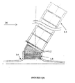
The proposed floating solar chimney is based on the seat (1.4) shown in figure la: - The Main Chimney (1.1) is composed by parts. This has double wall filled with lighter than air inflammable gas that creates the necessary buoyancy force. This lifting force compels the main chimney to take, without exterior winds, a vertical position.
- The Heavy Mobile Base (1.2) by which the main chimney is suspended. The total weight of this heavy base is bigger than the total buoyancy of the main chimney. This has a result, without exterior winds, the heavy mobile base to sit on the seat (1.4) of the chimney.
- The folding lower part of the chimney (1.3) which without exterior winds is inside the upper part of the seat.
- If exterior winds appear the main chimney (1.1) declines to a balance angle. The heavy base (1.2) supported in the edges of the seat receives also a corresponding declined position and the folding part of the chimney (1.3) that is fixed in the lower part of the Heavy Base, is lifted off and receives this decline, ensuring the continuity of the chimney as it appears in
figure 1b .
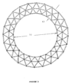
An indicative way of constructing a floating chimney is presented in the following paragraphs. The proposed way of construction is indicative, because there are several ways in doing so. The proposed construction is based on the idea of developing the main solar chimney with horizontal balloon cylindrical rings (Ring D1,figure 2 ) from flexible wrapping of balloons or airships (with a average surface density of 0,068 kg/sqm). Each cylindrical balloon ring D1 is filled with gas He (that gives a lifting force under regular conditions 10,36 Nt/m) or other light non flammable gas (e.g. NH3 with lift force under regular conditions 4,97 Nt/m). The ring has an orthogonal cross-section and valves of fulfillment. The dimensions of orthogonal cross-section of ring D1 depend mainly from the diameter of solar chimney. Each cylindrical ring D1 will be separated from next from durable, in horizontal stresses, supporting ring D2 (figure 3 ). Rings D2 will be manufactured by pipes of hard plastic or composed materials or aluminum with suitable diameter and thickness. Hence the ring D2 supports balloon ring D1 from compressive forces of deformity. The total weight of ring D2 has to be smaller than the remain lift force of the balloon ring D1. Thus each balloon ring D1 will be able to lift up to any atmospheric height as part of floating solar chimney, lifting together at least one ring D2. The exterior part of ring D2 will have suitable tips for the fastening of rings D2 between them, with the help of threads of high strength in order that intermediaryballoon rings D 1 to be under pressure.
The proposed floating solar chimney is a set of independent successive parts which are constituted by a constant number of balloon rings D1 and supporting rings D2. Each part is a compact durable set that can float due to its buoyancy. Each part of the chimney is suspended by at least three threads of high strength by the upper part of the Heavy Mobile Base (1.2), seefigure 1a .
Thus each part can receive any declined position imposed by exterior winds without problem. The successive parts of the floating chimney are separated, with a balloon ring D1, full from air from the environment which instead of valve of fulfillment, has a simple aperture or a special valve that allows air to enter and to come out depending on the relative movement of successive independent parts of chimney by variable exterior winds. With this intermediate air rings each part of the floating solar chimney becomes dynamically independent from the rests. The main floating solar chimney (1.1) is the sum of these successive and dynamically independent parts fastened independently to the Heavy Base. This set and every part of it can self float and stand the forces from the Bernoulli pressures by the internal updraft of warm air and the exterior winds. The thickness of balloon ring D1 is sufficient for he satisfactory heat insulation of the internal warm current of air that runs through the solar chimney from the exterior air that has lower temperature.
The main floating solar chimney (1.1) leads to its Heavy Mobile Base (1.2). The Heavy Mobile Base (1.2) is constituted by two rings of equal weight connected between them with exceptionally durable threads with high strength and high modulus, invested with flexible durable plastic films, so that it can receive any decline position while remains attached to the top of the seat of chimney. The total weight of the Heavy Base (1.2) exceeds the overall lift force of the main chimney and forms with this a single set. Under regular conditions the upper ring of the Heavy Base, which is manufactured with bigger diameter than the diameter of the upper part of the seat (1.4), sits on the seat of the chimney (1.4) while the lower ring, that has smaller diameter than the internal diameter of upper part of the seat (1.4), remains inside the seat (1.4) of chimney. By the lower part of the internal ring of the Heavy Base (1.2) is suspended the final folding part (1.3) of the floating solar chimney. This folding part (1.3), type accordion, is constructed in a similar way as the main chimney, with the difference that the balloon rings D1 that constitute it, instead of valve of fulfillment have a simple aperture (or a special valve) which allows the air of the environment to enter and to come out of them, depending on the decline of main solar chimney. The height of the folding part is calculated so that it can receive the maximum decline of the main solar chimney.
The threads of high strength and modulus, combined with the intermediate supporting rings D2, ensure the strength of this folding part to the forces that it accepts and they do not allow the deformity of its cross-section when it is declined and unfolded. This allows the smooth operation of the floating solar chimney when exterior winds appear that compel the solar chimney to receive a decline angle of balance. - If a floating solar chimney is free, without the presence of exterior winds, will have a vertical position, forced by the net lift force of main chimney's balloon rings D1, (
figure 1a ). The exterior winds compel the floating solar chimney to receive a decline which the heavy base follows and finally the folding part receives it, as shown infigure 1b . The angle of decline will be the one for which the normal drag force, from the vertical on the chimney component of the wind velocity, is equal to the counterbalancing component of net lift force of floating solar chimney.
In this case the dynamic field of flow of exterior winds facilitates the coming out of hot air at the top of the solar chimney, and consequently facilitates the updraft movement of warm air inside the main chimney.
This action potentially compensates the reduction of active height of floating solar chimneys due to the decline that receives when exterior winds appear. Thus the power output by floating solar chimney can be practically independent of exterior winds.
The appropriate place of installment of this solar power station should be chosen in order that the expected local winds do not exceed some strength for safety reasons. The threads of high strength via which becomes the fastening of the rings D2 between them and the final fastening to the Heavy Base (1.2) can ensure the safe withholding of the floating solar chimney under the most unfavorable conditions of exterior winds even if these do not have practical probability to appear.
The construction of a floating lighter than air chimney is feasible taking into consideration that the solar chimney is used exclusively for the up-drafting of warm air. Thus solar chimney stresses arise from the exterior winds and the Bernoulli pressure from the internal stream of warm air. A clever, simple and inexpensive construction can face these stresses effectively. The modem plastic and composed materials that are used for airships or balloons can be used for such a construction combining light weight and high strength in extreme stresses with long life under any exterior conditions.
Claims (1)
- A floating solar chimney comprising a lighter than air cylindrical structure used as a warm air up drafting operator when used in cooperation with a circular solar collector a set of air turbines geared to respective electric generator for electricity production, the lighter than air cylindrical structures providing thermal insulation to the rising air inside them
the floating solar chimney characterized, in that it further comprises :- an adjustable lighter than air cylindrical structure, comprising:
a main chimney unit (1.1) including a plurality of dynamically independent floating parts (1.5), wherein each dynamically independent floating part includes at least one tubular balloon ring made by fabric containing non-flammable, lighter - than - air gas, and wherein each dynamically independent floating part (1.5) further includes at least one supporting ring, made of aluminum, plastic or composite material ,in order to withstand compressive forces, and wherein the at least one cylindrical balloon ring and the at least one supporting ring of each dynamically independent floating part are interconnected, and wherein each dynamically independent floating part (1.5) is separated from the adjacent dynamically independent floating part (1.5) by an independent tubular balloon ring, made by fabric, filled with ambient air, configured to freely draw in and emit its air, whereby each dynamically independent floating part (1.5) is enabled to move independently from adjacent dynamically independent floating parts;
a base unit (1.2) coupled to the main chimney unit, wherein each dynamically independent floating part (1.5) of the main chimney unit (1.1) is fastened independently to the base unit (1.2), using at least three threads and wherein the base unit (1.2) includes an upper ring and a lower ring having equal weight and different exterior diameters, and wherein the upper ring and the lower ring are fixedly tied, and wherein the total weight of the base unit is larger than the net lift force of the main chimney unit;
a dynamically variable folding unit (1.3) coupled to the base unit(1.2), wherein the dynamically variable folding unit is fastened to the lower ring of the base unit and has a flexible, accordion - like configuration, and wherein the dynamically variable folding unit includes a plurality of balloon rings and a plurality of supporting rings, and wherein the plurality of balloon rings of the dynamically variable folding unit each have one of an aperture and a valve configured to freely draw in and emit ambient air, whereby the dynamically variable folding unit is configured to bend in accordance with the orientation of the main chimney unit (1.1) and the base unit (1.2), due to external winds (1.6);
and a chimney seat (1.4) configured to accommodate the base unit (1.2) and the dynamically variable folding unit (1.3), wherein at least a portion of the base unit (1.2) is seated on the top portion of the chimney seat (1.4), and wherein at least a portion of the dynamically variable folding unit (1.3) is contained within the chimney seat, and wherein an exterior diameter of the upper ring is larger than an exterior diameter of the chimney seat, and an exterior diameter of the lower ring is smaller than an internal diameter of the chimney seat.
Priority Applications (1)
| Application Number | Priority Date | Filing Date | Title |
|---|---|---|---|
| CY20091100566T CY1109105T1 (en) | 2003-03-27 | 2009-05-28 | Hovering Solar Chimney |
Applications Claiming Priority (2)
| Application Number | Priority Date | Filing Date | Title |
|---|---|---|---|
| GR20030100150A GR1004334B (en) | 2003-03-27 | 2003-03-27 | Self suspended solar chimney |
| PCT/GR2003/000037 WO2004085846A1 (en) | 2003-03-27 | 2003-09-08 | Floating solar chimney |
Publications (2)
| Publication Number | Publication Date |
|---|---|
| EP1618302A1 EP1618302A1 (en) | 2006-01-25 |
| EP1618302B1 true EP1618302B1 (en) | 2009-04-29 |
Family
ID=37492722
Family Applications (1)
| Application Number | Title | Priority Date | Filing Date |
|---|---|---|---|
| EP03816437A Expired - Lifetime EP1618302B1 (en) | 2003-03-27 | 2003-09-08 | Floating solar chimney |
Country Status (10)
| Country | Link |
|---|---|
| US (1) | US7735483B2 (en) |
| EP (1) | EP1618302B1 (en) |
| CN (1) | CN100374717C (en) |
| AT (1) | ATE430258T1 (en) |
| AU (1) | AU2003260797B2 (en) |
| DE (1) | DE60327472D1 (en) |
| ES (1) | ES2324781T3 (en) |
| GR (1) | GR1004334B (en) |
| WO (1) | WO2004085846A1 (en) |
| ZA (1) | ZA200507212B (en) |
Families Citing this family (21)
| Publication number | Priority date | Publication date | Assignee | Title |
|---|---|---|---|---|
| US7854224B2 (en) * | 2007-01-03 | 2010-12-21 | Pitaya Yangpichit | Solar chimney with internal and external solar collectors |
| US8166710B2 (en) | 2007-04-18 | 2012-05-01 | The Invention Science Fund I, Llc | High altitude structure for expelling a fluid stream through an annular space |
| US20080257977A1 (en) * | 2007-04-18 | 2008-10-23 | Searete Llc, A Limited Liability Corporation Of The State Of Delaware | High altitude atmospheric alteration system and method |
| US20100071771A1 (en) * | 2007-04-18 | 2010-03-25 | Searete Llc, A Limited Liability Corporation Of The State Of Delaware | High altitude atmospheric injection system and method |
| US8985477B2 (en) * | 2007-04-18 | 2015-03-24 | The Invention Science Fund I Llc | High altitude payload structures and related methods |
| US20080258006A1 (en) * | 2007-04-18 | 2008-10-23 | Searete Llc, A Limited Liability Corporation Of The State Of Delaware | High altitude structures control system and related methods |
| GB2451123A (en) * | 2007-07-20 | 2009-01-21 | Oz10 Ltd | A tent with a chimney vent |
| US20090152370A1 (en) * | 2007-12-18 | 2009-06-18 | Michael Gregory Pesochinsky | Chimney device and methods of using it to fight global warming, produce water precipitation and produce electricity |
| RU2374486C2 (en) * | 2008-01-23 | 2009-11-27 | Олег Николаевич Цепляев | Air-driven electric power station |
| US7821151B2 (en) * | 2008-02-23 | 2010-10-26 | Le John O | Hybrid solar thermal chimney |
| AT508047A1 (en) * | 2009-03-18 | 2010-10-15 | Univ Wien Tech | SUPPORT STRUCTURE |
| WO2011011341A2 (en) * | 2009-07-20 | 2011-01-27 | Slobodan Tepic | Generating electrical power utilizing surface-level hot air as the heat source, high atmosphere as the heat sink and a microwave beam to initiate and control air updraft |
| WO2012159611A2 (en) * | 2011-05-26 | 2012-11-29 | Machtwissen.De Ag | Devices for optimizing individual solar modules/collector modules and composite collector module groups and stabilizing the operation thereof against environmental influences, especially wind and particles and objects carried along by the wind |
| DE102013007836B3 (en) * | 2013-05-08 | 2014-05-28 | Franz Hegele | Tornado power plant for generating electrical energy, has chimney with hollow bodies filled with carrier gas e.g. hydrogen, and rotated with rotating frequency by drive, where base of chimney is rotatably supported around vertical axis |
| US20140375057A1 (en) * | 2013-06-23 | 2014-12-25 | Gaurav BAZAZ | Artificial wind generator |
| US10006443B1 (en) * | 2014-10-10 | 2018-06-26 | Stc.Unm | Inflatable, free-standing solar updraft tower with optimal geometry and active control |
| US10179630B2 (en) | 2015-02-18 | 2019-01-15 | Charles I. Wee | Floating community |
| CN105714689B (en) * | 2016-03-17 | 2017-11-17 | 王燏斌 | Bridge main tower sink-float construction method |
| CN105735133A (en) * | 2016-03-17 | 2016-07-06 | 王燏斌 | Pier sinking and floating construction method |
| US10648458B2 (en) | 2016-06-27 | 2020-05-12 | Martin E Nix | Downdraft and updraft tornado wind chimney |
| US11680750B1 (en) * | 2022-05-26 | 2023-06-20 | Iosif Gaportsin | System and method for green integrated electric power plant |
Family Cites Families (7)
| Publication number | Priority date | Publication date | Assignee | Title |
|---|---|---|---|---|
| US3918518A (en) * | 1974-03-15 | 1975-11-11 | Hudson Engineering Corp | Atmospheric heat exchangers |
| US4267824A (en) * | 1979-07-30 | 1981-05-19 | Hayakawa Associates | Solar concentrator |
| DE3006702A1 (en) * | 1980-02-20 | 1981-09-10 | Christian Dr.-Ing. 1000 Berlin Boes | Up-draft power plant using flexible tubular tower - supported by balloon or buoyancy chambers and having guide vanes at base to deflect entering air into turbine |
| IN180647B (en) * | 1993-03-11 | 1998-02-28 | Daya Ranjit Senanayake | |
| WO1996004443A1 (en) * | 1994-07-29 | 1996-02-15 | Daya Ranjit Senanayake | Chimney |
| DE29622549U1 (en) | 1996-12-30 | 1997-03-27 | Drabner Thomas | Wind power station |
| WO2004036039A1 (en) * | 2002-10-16 | 2004-04-29 | De Luca Kenneth A | Solar tower |
-
2003
- 2003-03-27 GR GR20030100150A patent/GR1004334B/en not_active IP Right Cessation
- 2003-09-08 AT AT03816437T patent/ATE430258T1/en not_active IP Right Cessation
- 2003-09-08 US US10/550,253 patent/US7735483B2/en not_active Expired - Fee Related
- 2003-09-08 DE DE60327472T patent/DE60327472D1/en not_active Expired - Lifetime
- 2003-09-08 EP EP03816437A patent/EP1618302B1/en not_active Expired - Lifetime
- 2003-09-08 WO PCT/GR2003/000037 patent/WO2004085846A1/en not_active Application Discontinuation
- 2003-09-08 CN CNB038259486A patent/CN100374717C/en not_active Expired - Fee Related
- 2003-09-08 ES ES03816437T patent/ES2324781T3/en not_active Expired - Lifetime
- 2003-09-08 AU AU2003260797A patent/AU2003260797B2/en not_active Ceased
-
2005
- 2005-09-08 ZA ZA200507212A patent/ZA200507212B/en unknown
Also Published As
| Publication number | Publication date |
|---|---|
| EP1618302A1 (en) | 2006-01-25 |
| ATE430258T1 (en) | 2009-05-15 |
| CN1742158A (en) | 2006-03-01 |
| WO2004085846A1 (en) | 2004-10-07 |
| GR1004334B (en) | 2003-09-11 |
| ES2324781T3 (en) | 2009-08-14 |
| AU2003260797A1 (en) | 2004-10-18 |
| US7735483B2 (en) | 2010-06-15 |
| CN100374717C (en) | 2008-03-12 |
| ZA200507212B (en) | 2006-05-31 |
| AU2003260797B2 (en) | 2010-08-26 |
| DE60327472D1 (en) | 2009-06-10 |
| US20060272240A1 (en) | 2006-12-07 |
Similar Documents
| Publication | Publication Date | Title |
|---|---|---|
| EP1618302B1 (en) | Floating solar chimney | |
| US4491739A (en) | Airship-floated wind turbine | |
| DK2379876T3 (en) | PELAGIC, SUSTAINABLE ENERGY SYSTEM | |
| US5404868A (en) | Apparatus using a balloon supported reflective surface for reflecting light from the sun | |
| WO2004036039A1 (en) | Solar tower | |
| EP0045202A1 (en) | Improvements in wind powered electric generators | |
| US20090096217A1 (en) | Wind turbine with perimeter power takeoff | |
| US5527216A (en) | Chimney | |
| US8127760B2 (en) | Low-cost heliostatic mirror with protective inflation stabilizable surface element means | |
| US20140105752A1 (en) | Drum pouch wind turbine | |
| NZ314482A (en) | Vertical axis wind turbine with outwardly extending flow directing wings | |
| US5266837A (en) | Apparatus for artifical wind power generation | |
| US20220106939A1 (en) | System for generating electricity | |
| US9546643B2 (en) | Revolving overhead windmill | |
| WO2017160825A1 (en) | Wind energy harvesting utilizing air shaft and centrifugal impellor wheels | |
| GB2404433A (en) | Balloon supported flexible chimney especially for use in solar power stations | |
| KR20200047805A (en) | Sail device | |
| JP7384047B2 (en) | power generation system | |
| JP2007205341A (en) | Solar heat wind power generation apparatus with balloon stack | |
| KR100736557B1 (en) | Typhoon Tower System | |
| JP3355487B2 (en) | Building materials | |
| Cr | optimurn Design for solar Power stations vyith Eloating solar ChIllIneys | |
| CN115492243A (en) | Three-dimensional urban super high-rise building and construction method thereof | |
| JP2007239725A (en) | Juxtaposing system of marine solar heat-wind power generation with balloon type chimney and screw power generation | |
| Hall | Weightless Solar Energy Collection," |
Legal Events
| Date | Code | Title | Description |
|---|---|---|---|
| PUAI | Public reference made under article 153(3) epc to a published international application that has entered the european phase |
Free format text: ORIGINAL CODE: 0009012 |
|
| 17P | Request for examination filed |
Effective date: 20051011 |
|
| AK | Designated contracting states |
Kind code of ref document: A1 Designated state(s): AT BE BG CH CY CZ DE DK EE ES FI FR GB GR HU IE IT LI LU MC NL PT RO SE SI SK TR |
|
| AX | Request for extension of the european patent |
Extension state: AL LT LV MK |
|
| DAX | Request for extension of the european patent (deleted) | ||
| GRAP | Despatch of communication of intention to grant a patent |
Free format text: ORIGINAL CODE: EPIDOSNIGR1 |
|
| GRAS | Grant fee paid |
Free format text: ORIGINAL CODE: EPIDOSNIGR3 |
|
| GRAA | (expected) grant |
Free format text: ORIGINAL CODE: 0009210 |
|
| AK | Designated contracting states |
Kind code of ref document: B1 Designated state(s): AT BE BG CH CY CZ DE DK EE ES FI FR GB GR HU IE IT LI LU MC NL PT RO SE SI SK TR |
|
| REG | Reference to a national code |
Ref country code: GB Ref legal event code: FG4D |
|
| REG | Reference to a national code |
Ref country code: CH Ref legal event code: EP |
|
| REF | Corresponds to: |
Ref document number: 60327472 Country of ref document: DE Date of ref document: 20090610 Kind code of ref document: P |
|
| REG | Reference to a national code |
Ref country code: IE Ref legal event code: FG4D |
|
| REG | Reference to a national code |
Ref country code: ES Ref legal event code: FG2A Ref document number: 2324781 Country of ref document: ES Kind code of ref document: T3 |
|
| NLV1 | Nl: lapsed or annulled due to failure to fulfill the requirements of art. 29p and 29m of the patents act | ||
| PG25 | Lapsed in a contracting state [announced via postgrant information from national office to epo] |
Ref country code: PT Free format text: LAPSE BECAUSE OF FAILURE TO SUBMIT A TRANSLATION OF THE DESCRIPTION OR TO PAY THE FEE WITHIN THE PRESCRIBED TIME-LIMIT Effective date: 20090829 Ref country code: AT Free format text: LAPSE BECAUSE OF FAILURE TO SUBMIT A TRANSLATION OF THE DESCRIPTION OR TO PAY THE FEE WITHIN THE PRESCRIBED TIME-LIMIT Effective date: 20090429 Ref country code: FI Free format text: LAPSE BECAUSE OF FAILURE TO SUBMIT A TRANSLATION OF THE DESCRIPTION OR TO PAY THE FEE WITHIN THE PRESCRIBED TIME-LIMIT Effective date: 20090429 |
|
| PG25 | Lapsed in a contracting state [announced via postgrant information from national office to epo] |
Ref country code: SE Free format text: LAPSE BECAUSE OF FAILURE TO SUBMIT A TRANSLATION OF THE DESCRIPTION OR TO PAY THE FEE WITHIN THE PRESCRIBED TIME-LIMIT Effective date: 20090729 Ref country code: SI Free format text: LAPSE BECAUSE OF FAILURE TO SUBMIT A TRANSLATION OF THE DESCRIPTION OR TO PAY THE FEE WITHIN THE PRESCRIBED TIME-LIMIT Effective date: 20090429 Ref country code: NL Free format text: LAPSE BECAUSE OF FAILURE TO SUBMIT A TRANSLATION OF THE DESCRIPTION OR TO PAY THE FEE WITHIN THE PRESCRIBED TIME-LIMIT Effective date: 20090429 |
|
| PG25 | Lapsed in a contracting state [announced via postgrant information from national office to epo] |
Ref country code: EE Free format text: LAPSE BECAUSE OF FAILURE TO SUBMIT A TRANSLATION OF THE DESCRIPTION OR TO PAY THE FEE WITHIN THE PRESCRIBED TIME-LIMIT Effective date: 20090429 Ref country code: CZ Free format text: LAPSE BECAUSE OF FAILURE TO SUBMIT A TRANSLATION OF THE DESCRIPTION OR TO PAY THE FEE WITHIN THE PRESCRIBED TIME-LIMIT Effective date: 20090429 Ref country code: DK Free format text: LAPSE BECAUSE OF FAILURE TO SUBMIT A TRANSLATION OF THE DESCRIPTION OR TO PAY THE FEE WITHIN THE PRESCRIBED TIME-LIMIT Effective date: 20090429 Ref country code: RO Free format text: LAPSE BECAUSE OF FAILURE TO SUBMIT A TRANSLATION OF THE DESCRIPTION OR TO PAY THE FEE WITHIN THE PRESCRIBED TIME-LIMIT Effective date: 20090429 |
|
| PG25 | Lapsed in a contracting state [announced via postgrant information from national office to epo] |
Ref country code: SK Free format text: LAPSE BECAUSE OF FAILURE TO SUBMIT A TRANSLATION OF THE DESCRIPTION OR TO PAY THE FEE WITHIN THE PRESCRIBED TIME-LIMIT Effective date: 20090429 Ref country code: BE Free format text: LAPSE BECAUSE OF FAILURE TO SUBMIT A TRANSLATION OF THE DESCRIPTION OR TO PAY THE FEE WITHIN THE PRESCRIBED TIME-LIMIT Effective date: 20090429 |
|
| PLBE | No opposition filed within time limit |
Free format text: ORIGINAL CODE: 0009261 |
|
| STAA | Information on the status of an ep patent application or granted ep patent |
Free format text: STATUS: NO OPPOSITION FILED WITHIN TIME LIMIT |
|
| PG25 | Lapsed in a contracting state [announced via postgrant information from national office to epo] |
Ref country code: BG Free format text: LAPSE BECAUSE OF FAILURE TO SUBMIT A TRANSLATION OF THE DESCRIPTION OR TO PAY THE FEE WITHIN THE PRESCRIBED TIME-LIMIT Effective date: 20090729 |
|
| 26N | No opposition filed |
Effective date: 20100201 |
|
| PG25 | Lapsed in a contracting state [announced via postgrant information from national office to epo] |
Ref country code: MC Free format text: LAPSE BECAUSE OF NON-PAYMENT OF DUE FEES Effective date: 20090930 |
|
| REG | Reference to a national code |
Ref country code: CH Ref legal event code: PL |
|
| GBPC | Gb: european patent ceased through non-payment of renewal fee |
Effective date: 20090908 |
|
| REG | Reference to a national code |
Ref country code: IE Ref legal event code: MM4A |
|
| PG25 | Lapsed in a contracting state [announced via postgrant information from national office to epo] |
Ref country code: IE Free format text: LAPSE BECAUSE OF NON-PAYMENT OF DUE FEES Effective date: 20090908 |
|
| PG25 | Lapsed in a contracting state [announced via postgrant information from national office to epo] |
Ref country code: GR Free format text: LAPSE BECAUSE OF FAILURE TO SUBMIT A TRANSLATION OF THE DESCRIPTION OR TO PAY THE FEE WITHIN THE PRESCRIBED TIME-LIMIT Effective date: 20090730 Ref country code: CH Free format text: LAPSE BECAUSE OF NON-PAYMENT OF DUE FEES Effective date: 20090930 Ref country code: LI Free format text: LAPSE BECAUSE OF NON-PAYMENT OF DUE FEES Effective date: 20090930 |
|
| PG25 | Lapsed in a contracting state [announced via postgrant information from national office to epo] |
Ref country code: GB Free format text: LAPSE BECAUSE OF NON-PAYMENT OF DUE FEES Effective date: 20090908 |
|
| PGFP | Annual fee paid to national office [announced via postgrant information from national office to epo] |
Ref country code: CY Payment date: 20100706 Year of fee payment: 8 Ref country code: DE Payment date: 20100922 Year of fee payment: 8 |
|
| PG25 | Lapsed in a contracting state [announced via postgrant information from national office to epo] |
Ref country code: LU Free format text: LAPSE BECAUSE OF NON-PAYMENT OF DUE FEES Effective date: 20090908 |
|
| PG25 | Lapsed in a contracting state [announced via postgrant information from national office to epo] |
Ref country code: HU Free format text: LAPSE BECAUSE OF FAILURE TO SUBMIT A TRANSLATION OF THE DESCRIPTION OR TO PAY THE FEE WITHIN THE PRESCRIBED TIME-LIMIT Effective date: 20091030 |
|
| PGFP | Annual fee paid to national office [announced via postgrant information from national office to epo] |
Ref country code: TR Payment date: 20110516 Year of fee payment: 9 |
|
| PGFP | Annual fee paid to national office [announced via postgrant information from national office to epo] |
Ref country code: IT Payment date: 20110517 Year of fee payment: 9 |
|
| PGFP | Annual fee paid to national office [announced via postgrant information from national office to epo] |
Ref country code: FR Payment date: 20111004 Year of fee payment: 9 Ref country code: ES Payment date: 20110707 Year of fee payment: 9 |
|
| PG25 | Lapsed in a contracting state [announced via postgrant information from national office to epo] |
Ref country code: CY Free format text: LAPSE BECAUSE OF NON-PAYMENT OF DUE FEES Effective date: 20110908 |
|
| REG | Reference to a national code |
Ref country code: FR Ref legal event code: ST Effective date: 20130531 |
|
| PG25 | Lapsed in a contracting state [announced via postgrant information from national office to epo] |
Ref country code: DE Free format text: LAPSE BECAUSE OF NON-PAYMENT OF DUE FEES Effective date: 20130403 |
|
| PG25 | Lapsed in a contracting state [announced via postgrant information from national office to epo] |
Ref country code: IT Free format text: LAPSE BECAUSE OF NON-PAYMENT OF DUE FEES Effective date: 20120908 Ref country code: FR Free format text: LAPSE BECAUSE OF NON-PAYMENT OF DUE FEES Effective date: 20121001 |
|
| REG | Reference to a national code |
Ref country code: DE Ref legal event code: R119 Ref document number: 60327472 Country of ref document: DE Effective date: 20130403 |
|
| REG | Reference to a national code |
Ref country code: ES Ref legal event code: FD2A Effective date: 20131018 |
|
| PG25 | Lapsed in a contracting state [announced via postgrant information from national office to epo] |
Ref country code: ES Free format text: LAPSE BECAUSE OF NON-PAYMENT OF DUE FEES Effective date: 20120909 |
|
| PG25 | Lapsed in a contracting state [announced via postgrant information from national office to epo] |
Ref country code: TR Free format text: LAPSE BECAUSE OF NON-PAYMENT OF DUE FEES Effective date: 20120908 |