EP1617794B1 - Calf and foot support and adjustment assembly - Google Patents
Calf and foot support and adjustment assembly Download PDFInfo
- Publication number
- EP1617794B1 EP1617794B1 EP04759515A EP04759515A EP1617794B1 EP 1617794 B1 EP1617794 B1 EP 1617794B1 EP 04759515 A EP04759515 A EP 04759515A EP 04759515 A EP04759515 A EP 04759515A EP 1617794 B1 EP1617794 B1 EP 1617794B1
- Authority
- EP
- European Patent Office
- Prior art keywords
- foot
- calf
- support assembly
- assembly
- treatment table
- Prior art date
- Legal status (The legal status is an assumption and is not a legal conclusion. Google has not performed a legal analysis and makes no representation as to the accuracy of the status listed.)
- Expired - Lifetime
Links
- 244000309466 calf Species 0.000 title claims description 49
- 210000002683 foot Anatomy 0.000 claims description 118
- 210000003423 ankle Anatomy 0.000 claims description 9
- 238000005266 casting Methods 0.000 description 10
- 238000009232 chiropractic Methods 0.000 description 4
- 239000000463 material Substances 0.000 description 4
- 206010048961 Localised oedema Diseases 0.000 description 3
- 230000005484 gravity Effects 0.000 description 3
- 210000002414 leg Anatomy 0.000 description 3
- 230000007246 mechanism Effects 0.000 description 3
- 238000002560 therapeutic procedure Methods 0.000 description 3
- 208000003618 Intervertebral Disc Displacement Diseases 0.000 description 2
- 210000004712 air sac Anatomy 0.000 description 2
- 230000009286 beneficial effect Effects 0.000 description 2
- 230000000694 effects Effects 0.000 description 2
- 210000004705 lumbosacral region Anatomy 0.000 description 2
- 238000012423 maintenance Methods 0.000 description 2
- 210000003205 muscle Anatomy 0.000 description 2
- 230000001144 postural effect Effects 0.000 description 2
- PICXIOQBANWBIZ-UHFFFAOYSA-N zinc;1-oxidopyridine-2-thione Chemical class [Zn+2].[O-]N1C=CC=CC1=S.[O-]N1C=CC=CC1=S PICXIOQBANWBIZ-UHFFFAOYSA-N 0.000 description 2
- 208000025940 Back injury Diseases 0.000 description 1
- 241000282412 Homo Species 0.000 description 1
- 206010050296 Intervertebral disc protrusion Diseases 0.000 description 1
- 208000007623 Lordosis Diseases 0.000 description 1
- 208000020307 Spinal disease Diseases 0.000 description 1
- 230000009471 action Effects 0.000 description 1
- 210000003484 anatomy Anatomy 0.000 description 1
- 230000000712 assembly Effects 0.000 description 1
- 238000000429 assembly Methods 0.000 description 1
- 210000001124 body fluid Anatomy 0.000 description 1
- 239000010839 body fluid Substances 0.000 description 1
- 210000000988 bone and bone Anatomy 0.000 description 1
- 210000001217 buttock Anatomy 0.000 description 1
- 230000008859 change Effects 0.000 description 1
- 230000001419 dependent effect Effects 0.000 description 1
- 208000037265 diseases, disorders, signs and symptoms Diseases 0.000 description 1
- 208000035475 disorder Diseases 0.000 description 1
- 239000003814 drug Substances 0.000 description 1
- 230000004064 dysfunction Effects 0.000 description 1
- 230000036541 health Effects 0.000 description 1
- 230000006872 improvement Effects 0.000 description 1
- 210000003127 knee Anatomy 0.000 description 1
- 210000004446 longitudinal ligament Anatomy 0.000 description 1
- 210000003141 lower extremity Anatomy 0.000 description 1
- 210000005036 nerve Anatomy 0.000 description 1
- 230000009467 reduction Effects 0.000 description 1
- 230000000284 resting effect Effects 0.000 description 1
- 238000000926 separation method Methods 0.000 description 1
- 230000035939 shock Effects 0.000 description 1
- 210000000273 spinal nerve root Anatomy 0.000 description 1
- 239000000725 suspension Substances 0.000 description 1
- 230000001225 therapeutic effect Effects 0.000 description 1
- 210000001519 tissue Anatomy 0.000 description 1
- 210000001835 viscera Anatomy 0.000 description 1
Images






Classifications
-
- A—HUMAN NECESSITIES
- A61—MEDICAL OR VETERINARY SCIENCE; HYGIENE
- A61H—PHYSICAL THERAPY APPARATUS, e.g. DEVICES FOR LOCATING OR STIMULATING REFLEX POINTS IN THE BODY; ARTIFICIAL RESPIRATION; MASSAGE; BATHING DEVICES FOR SPECIAL THERAPEUTIC OR HYGIENIC PURPOSES OR SPECIFIC PARTS OF THE BODY
- A61H1/00—Apparatus for passive exercising; Vibrating apparatus; Chiropractic devices, e.g. body impacting devices, external devices for briefly extending or aligning unbroken bones
- A61H1/02—Stretching or bending or torsioning apparatus for exercising
- A61H1/0237—Stretching or bending or torsioning apparatus for exercising for the lower limbs
-
- A—HUMAN NECESSITIES
- A61—MEDICAL OR VETERINARY SCIENCE; HYGIENE
- A61G—TRANSPORT, PERSONAL CONVEYANCES, OR ACCOMMODATION SPECIALLY ADAPTED FOR PATIENTS OR DISABLED PERSONS; OPERATING TABLES OR CHAIRS; CHAIRS FOR DENTISTRY; FUNERAL DEVICES
- A61G13/00—Operating tables; Auxiliary appliances therefor
- A61G13/009—Physiotherapeutic tables, beds or platforms; Chiropractic or osteopathic tables
-
- A—HUMAN NECESSITIES
- A61—MEDICAL OR VETERINARY SCIENCE; HYGIENE
- A61G—TRANSPORT, PERSONAL CONVEYANCES, OR ACCOMMODATION SPECIALLY ADAPTED FOR PATIENTS OR DISABLED PERSONS; OPERATING TABLES OR CHAIRS; CHAIRS FOR DENTISTRY; FUNERAL DEVICES
- A61G13/00—Operating tables; Auxiliary appliances therefor
- A61G13/10—Parts, details or accessories
- A61G13/12—Rests specially adapted therefor; Arrangements of patient-supporting surfaces
-
- A—HUMAN NECESSITIES
- A61—MEDICAL OR VETERINARY SCIENCE; HYGIENE
- A61H—PHYSICAL THERAPY APPARATUS, e.g. DEVICES FOR LOCATING OR STIMULATING REFLEX POINTS IN THE BODY; ARTIFICIAL RESPIRATION; MASSAGE; BATHING DEVICES FOR SPECIAL THERAPEUTIC OR HYGIENIC PURPOSES OR SPECIFIC PARTS OF THE BODY
- A61H1/00—Apparatus for passive exercising; Vibrating apparatus; Chiropractic devices, e.g. body impacting devices, external devices for briefly extending or aligning unbroken bones
- A61H1/02—Stretching or bending or torsioning apparatus for exercising
- A61H1/0218—Drawing-out devices
- A61H1/0222—Traction tables
-
- A—HUMAN NECESSITIES
- A61—MEDICAL OR VETERINARY SCIENCE; HYGIENE
- A61H—PHYSICAL THERAPY APPARATUS, e.g. DEVICES FOR LOCATING OR STIMULATING REFLEX POINTS IN THE BODY; ARTIFICIAL RESPIRATION; MASSAGE; BATHING DEVICES FOR SPECIAL THERAPEUTIC OR HYGIENIC PURPOSES OR SPECIFIC PARTS OF THE BODY
- A61H1/00—Apparatus for passive exercising; Vibrating apparatus; Chiropractic devices, e.g. body impacting devices, external devices for briefly extending or aligning unbroken bones
- A61H1/02—Stretching or bending or torsioning apparatus for exercising
- A61H1/0218—Drawing-out devices
- A61H1/0229—Drawing-out devices by reducing gravity forces normally applied to the body, e.g. by lifting or hanging the body or part of it
-
- A—HUMAN NECESSITIES
- A61—MEDICAL OR VETERINARY SCIENCE; HYGIENE
- A61G—TRANSPORT, PERSONAL CONVEYANCES, OR ACCOMMODATION SPECIALLY ADAPTED FOR PATIENTS OR DISABLED PERSONS; OPERATING TABLES OR CHAIRS; CHAIRS FOR DENTISTRY; FUNERAL DEVICES
- A61G13/00—Operating tables; Auxiliary appliances therefor
- A61G13/10—Parts, details or accessories
- A61G13/12—Rests specially adapted therefor; Arrangements of patient-supporting surfaces
- A61G13/1205—Rests specially adapted therefor; Arrangements of patient-supporting surfaces for specific parts of the body
- A61G13/121—Head or neck
-
- A—HUMAN NECESSITIES
- A61—MEDICAL OR VETERINARY SCIENCE; HYGIENE
- A61G—TRANSPORT, PERSONAL CONVEYANCES, OR ACCOMMODATION SPECIALLY ADAPTED FOR PATIENTS OR DISABLED PERSONS; OPERATING TABLES OR CHAIRS; CHAIRS FOR DENTISTRY; FUNERAL DEVICES
- A61G13/00—Operating tables; Auxiliary appliances therefor
- A61G13/10—Parts, details or accessories
- A61G13/12—Rests specially adapted therefor; Arrangements of patient-supporting surfaces
- A61G13/1205—Rests specially adapted therefor; Arrangements of patient-supporting surfaces for specific parts of the body
- A61G13/1225—Back
-
- A—HUMAN NECESSITIES
- A61—MEDICAL OR VETERINARY SCIENCE; HYGIENE
- A61G—TRANSPORT, PERSONAL CONVEYANCES, OR ACCOMMODATION SPECIALLY ADAPTED FOR PATIENTS OR DISABLED PERSONS; OPERATING TABLES OR CHAIRS; CHAIRS FOR DENTISTRY; FUNERAL DEVICES
- A61G13/00—Operating tables; Auxiliary appliances therefor
- A61G13/10—Parts, details or accessories
- A61G13/12—Rests specially adapted therefor; Arrangements of patient-supporting surfaces
- A61G13/1205—Rests specially adapted therefor; Arrangements of patient-supporting surfaces for specific parts of the body
- A61G13/1235—Arms
-
- A—HUMAN NECESSITIES
- A61—MEDICAL OR VETERINARY SCIENCE; HYGIENE
- A61G—TRANSPORT, PERSONAL CONVEYANCES, OR ACCOMMODATION SPECIALLY ADAPTED FOR PATIENTS OR DISABLED PERSONS; OPERATING TABLES OR CHAIRS; CHAIRS FOR DENTISTRY; FUNERAL DEVICES
- A61G13/00—Operating tables; Auxiliary appliances therefor
- A61G13/10—Parts, details or accessories
- A61G13/12—Rests specially adapted therefor; Arrangements of patient-supporting surfaces
- A61G13/1205—Rests specially adapted therefor; Arrangements of patient-supporting surfaces for specific parts of the body
- A61G13/124—Hands or wrists
-
- A—HUMAN NECESSITIES
- A61—MEDICAL OR VETERINARY SCIENCE; HYGIENE
- A61G—TRANSPORT, PERSONAL CONVEYANCES, OR ACCOMMODATION SPECIALLY ADAPTED FOR PATIENTS OR DISABLED PERSONS; OPERATING TABLES OR CHAIRS; CHAIRS FOR DENTISTRY; FUNERAL DEVICES
- A61G13/00—Operating tables; Auxiliary appliances therefor
- A61G13/10—Parts, details or accessories
- A61G13/12—Rests specially adapted therefor; Arrangements of patient-supporting surfaces
- A61G13/1205—Rests specially adapted therefor; Arrangements of patient-supporting surfaces for specific parts of the body
- A61G13/1245—Knees, upper or lower legs
-
- A—HUMAN NECESSITIES
- A61—MEDICAL OR VETERINARY SCIENCE; HYGIENE
- A61G—TRANSPORT, PERSONAL CONVEYANCES, OR ACCOMMODATION SPECIALLY ADAPTED FOR PATIENTS OR DISABLED PERSONS; OPERATING TABLES OR CHAIRS; CHAIRS FOR DENTISTRY; FUNERAL DEVICES
- A61G13/00—Operating tables; Auxiliary appliances therefor
- A61G13/10—Parts, details or accessories
- A61G13/12—Rests specially adapted therefor; Arrangements of patient-supporting surfaces
- A61G13/1205—Rests specially adapted therefor; Arrangements of patient-supporting surfaces for specific parts of the body
- A61G13/125—Ankles or feet
-
- A—HUMAN NECESSITIES
- A61—MEDICAL OR VETERINARY SCIENCE; HYGIENE
- A61G—TRANSPORT, PERSONAL CONVEYANCES, OR ACCOMMODATION SPECIALLY ADAPTED FOR PATIENTS OR DISABLED PERSONS; OPERATING TABLES OR CHAIRS; CHAIRS FOR DENTISTRY; FUNERAL DEVICES
- A61G13/00—Operating tables; Auxiliary appliances therefor
- A61G13/10—Parts, details or accessories
- A61G13/12—Rests specially adapted therefor; Arrangements of patient-supporting surfaces
- A61G13/1205—Rests specially adapted therefor; Arrangements of patient-supporting surfaces for specific parts of the body
- A61G13/1255—Shoulders
-
- A—HUMAN NECESSITIES
- A61—MEDICAL OR VETERINARY SCIENCE; HYGIENE
- A61G—TRANSPORT, PERSONAL CONVEYANCES, OR ACCOMMODATION SPECIALLY ADAPTED FOR PATIENTS OR DISABLED PERSONS; OPERATING TABLES OR CHAIRS; CHAIRS FOR DENTISTRY; FUNERAL DEVICES
- A61G2200/00—Information related to the kind of patient or his position
- A61G2200/30—Specific positions of the patient
- A61G2200/32—Specific positions of the patient lying
- A61G2200/322—Specific positions of the patient lying lateral
-
- A—HUMAN NECESSITIES
- A61—MEDICAL OR VETERINARY SCIENCE; HYGIENE
- A61G—TRANSPORT, PERSONAL CONVEYANCES, OR ACCOMMODATION SPECIALLY ADAPTED FOR PATIENTS OR DISABLED PERSONS; OPERATING TABLES OR CHAIRS; CHAIRS FOR DENTISTRY; FUNERAL DEVICES
- A61G2200/00—Information related to the kind of patient or his position
- A61G2200/30—Specific positions of the patient
- A61G2200/32—Specific positions of the patient lying
- A61G2200/325—Specific positions of the patient lying prone
Definitions
- the within invention is an improvement of the inventions of my U.S. Patent Nos. 4,915,101 (1990 ), 5,922,011 (1999 ), and that reflected in my Application Serial No. 09/661,078, filed September 13, 2000 .
- U.S. Patent No. 4,568,669 (1971 ) to Stiles discloses a posture board wherein the patient is rotated 180 degrees from an initial upright position on his back to one of complete inversion hanging by the ankles. With the body hanging freely, normal gravitational pull is reversed thus causing a therapeutic effect on bone structure, spinal column, muscles, internal organs and body fluids.
- U.S. Patent No. 4,292,926 (1981) to Krause presents an apparatus for effecting postural treatment of humans in which the patient, while resting face down on a pivoting platform, can vary the position of his arms, adjust his center of gravity while in suspension and, thereby, affect his posture upon the table.
- any device designated to treat lower back dysfunction is in large part dependent on proper positioning of the patient prior to, during, and after treatment.
- the patient wears a pelvic harness and is positioned supinely (face up) in bed, with the spine slightly flexed and knees bent. Straps or roping which is attached to the harness are then inserted into a pulley mechanism and weights attached at an opposite end, causing a desired pulling/traction effect.
- Such pulling traction force produces an elongation of the spinal column (distraction) and a reduction in internal intervertebral disc pressure. This creates a vacuum phenomenon inside the disc, which retracts protruded gelatinous material back into its fibrous casing and off of the spinal nerve roots. With the pain gone and the anatomy restored to its natural state, the traction phase of therapy is complete.
- US-A-3 238 936 describes an apparatus for mechanical corrective therapy according to the preamble of claim 1.
- This apparatus is equipped with means for linear movement, however the carriage is not pivotally attached to the table. Furthermore, this known apparatus does not have means enabling vertical or lateral movement of the carriage.
- the present invention being both beneficial to the patient and convenient to the doctor, fulfills this need in a variety of ways in that the inventive treatment table not only enables rotation of a patient about a pivot point but, additionally, permits the relative, selectable positioning of the patient's arms, upper torso, legs, lower back, head and shoulders through manual adjustment or an automatic keypad control.
- the present invention also allows a complete choice as to prone, supine or lateral positioning of the patient prior to treatment.
- doctor to vary the position of the patient prior to and during treatment, and to vary the degree of tractive force applied to the patient by selectably variably rotating the patient platform to increase or decrease the tractional gravitational pull applied through such rotation.
- a "dynamic rotation" into a variable vertical traction position, i.e., the patient stands upright against the table, supported by an adjustable shoulder, arm and hand support and is lifted off the ground, thereby achieving tractional dynamics related to those described above, namely a rapid lengthening of the muscles and longitudinal ligaments of the spine increasing the separation of the intervertebral disc and articular joint spaces.
- My instant invention therefore defines functionally over the structure of my earlier inventions in the following material respects:
- a foot and calf support and treatment table for extension, flexion, traction, distraction and lateral movement of the spine and lower body of a patient is provided as defined in claim 1.
- the table more particularly includes a base adapted to rest upon a floor, and system support means having an upper end and a lower end integrally secured to said base, said support means including a pivot axis proximal to said upper end thereof.
- the treatment table also includes means for selectable reciprocal extension having an upper end and a lower end, one end pivotally attached to said system support means, said selectable extension means providing reciprocal movement of said one end relative to an opposite end thereof.
- the table further includes a rigid support platform having an upper end and a lower end, said platform pivotally secured to said pivot axis of said support means and, further, pivotally secured to said one end of said selectable extension means, thereby providing a resultant rotational motion of the support platform.
- the treatment table yet further includes a body support assembly adjustably positionable relative to said rigid support platform, said assembly having an upper end and a lower end; and means for enabling said patient to remain on said body support assembly during rotational movement thereof.
- a principal object of the invention is to provide a multi-purpose table to effectuate flexion, extension, traction, lateral movement and distraction of the spine, as may be required in the treatment of spinal disorders and/or maintenance of proper human posture, in such a manner that the relative positions of the patient's arms, legs, lower back, head and shoulders can be varied.
- Another object is to provide a multipurpose rotatable traction/treatment table permitting patient rotation and dynamic lifting of a patient while standing, concurrently with selective patient body positionings as may be required in the treatment of disc herniations and other disorders and/or maintenance of proper human posture.
- Yet another object of the invention is to provide a treatment table having a range of motion from zero to at least ninety degrees and, within that range, which can pivot from zero to at least ninety degrees, thereby providing the ability to achieve spinal positioning including spinal flexion, extension, lateral flexion, and axial spinal positioning and traction in the absence of a lower leg support assembly enabled by inherent torso support and placement of the human body at or near its center of gravity at the lower back support assembly.
- a still further object is to provide a table which having a variety of pneumatic and other adjustments to permit that patients of widely disparate age, height and weight to be accommodated, without requirement of extended physician set up time.
- Another object of the invention is to provide a multi-purpose table that is simple to operate, weighted and designed for safety so as not to tip, and constructed of quality materials.
- a yet further object is to provide a system in which the position of the upper torso support assembly may be varied relative to the lower back support assembly.
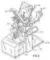
- the present chiropractic treatment table for effecting extension, flexion, traction and distraction of the spine of a patient may be seen to include a base 10 adapted to rest upon a floor 12 in a typical treatment room of a chiropractor, physical therapist, or other health professionals involved in physical medicine, and a system support 15 integrally secured to the base.
- the chiropractic table may be seen to optionally include a pair of elevation means 14 and 16 to enable positioning of patients of various heights on the table.
- Elevation means 14 and 16 preferably comprise extensible hydraulic pistons, each including upper ends which support a pivot axle 22.
- pivot axle 22 is journalled within channel 23 of block support 25 of rigid upper body support platform 26.
- the instant multi-purpose treatment table thereby includes said upper support platform 26 having an upper part 28 and a lower part 30.
- Said lower part 30 of rigid support platform 26 is secured to said pivot block 25 (see Fig. 3 ) which is rotatable upon said pivot axle 22 at the approximate mid-point of lower part 30 of platform 26.
- said upper part 28 defines a plane which is directed at an angle of about thirty degrees relative to a plane defined by said lower part 30 of the upper support platform 26. Such an angle is necessary in that it allows the patient's upper body to be ergonomically supported by a body support assembly 32 (See Fig. 1 ), permitting the back to extend convexly and backward relative to base 10.
- Support assembly 32 is mounted upon said upper part 28 of said rigid support platform 26.
- Said body support assembly may or may not be divided into, and may or may not include, moveable sections with hydraulic or pneumatic pistons or other means for elevation and de-elevation of the body support assembly 32.
- Said body support assembly may contain an integral air bladder for additional immobilization.
- the system may also be seen to optionally include a pair of positionally adjustable arm support means 42 and 44 which are located proximally to the sides of a body support assembly 32.
- said arm support means include a selectably adjustable rear portion 46 which is secured to said upper part 28 of the rigid support platform 26.
- Said arm support means 42 and 44 include (i) substantially horizontal arm rests 50; (ii) a chest and shoulder support 51 situated posteriorly and angled inwardly in a patient direction from said arm rest; and (iii) a tilted hand grip 52 depending integrally upwardly and inwardly, proximally to said chest and shoulder supports 51.
- the present treatment table may be seen to further include a lumbar and buttock support assembly 40, which is displaced from said body support assembly 32.
- Lumbar assembly 40 is connected to telescoping piston rods 53 and 55 (see Fig. 3 ) or other means which provide for elevation and de-elevation thereof.
- Said lumbar assembly may include an internal air cushion in the form of an inflatable air bladder, for added support and tissue mobilization. The same is true of the upper torso support assembly.
- Foot-and-calf assembly control bar 209 and foot rest 202 may also be seen in Fig. 1 .
- Fig. 3 is shown a general view of lumbar back assembly 160 and of calf/foot support assembly 200. Therein, said figure depicts a general position of the lumbar support assembly in relation to the calf/foot support assembly and rigid support platform 26, including upper and lower portions of 28 and 30 respectively, associated with the platform 26. Also, shown in Fig. 3 is lumbar cushion 40 and lumbar cushion hydraulic/pneumatic extension rods 53/55 which, in combination with hydraulic pistons 138/139, determine the angle of the lumbar cushion relative to lower portion 30 of the rigid support platform 26.
- Said cylinders 138/139 rest upon a rigid support frame plate 150 which itself is supported by a rigid support frame space bar 152 and a block support 25 which includes a main horizontal axial channel 23 through which pivot axle 22 (see Figs. 1 and 2 ).
- calf/foot support link casting 212 Further shown in Fig. 3 is calf/foot support link casting 212, foot tubing 214, foot rest 202 and ankle cushion 204, all of calf/foot support assembly 200. Also shown therein is side-swing mechanism 290 of calf/foot support assembly 200.
- Fig. 4 is a more detailed illustration of the calf/foot support assembly and its relationship to rigid support platform 26. More particularly, therein are shown calf/foot support assembly vertical positioning hydraulics 208 and their relationship to said calf/foot support link casting 212 and lumbar support casting 112. Also shown is link casting axle 213 of the calf/foot support link casting 212, said side-swing assembly 290 and its transverse bar 215, foot tubing 214, foot side bracket 274, foot lock housing 264, foot rest 202, ankle cushion 204, and calf/foot support assembly control bar 209. Also shown therein are arrows U, D, R, and L which illustrate the up-down and left-right degrees of freedom of the calf/foot support assembly 200.
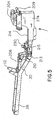
- the calf/foot support assembly 200 is shown in a raised position in Fig. 5 .
- the vertical-positioning hydraulic rods 208 are shown fully retracted, the same corresponding the upper limit of the vertical position of the assembly.
- Fig. 6 is shown a general view of the calf/foot support assembly in which the mid-section covers thereof have been removed. It is noted that the subassemblies of the calf/foot support assembly rest upon foot tubing 214 (see also Fig. 5 ) that is pivotally attached for the calf/foot support link casting 212, which itself is pivotally attached to the rigid support platform (see axial 213) for vertically positioning, thereby permitting the calf/foot support assembly to be lifted up to 30° above the horizontal plane of lower part 30 and as much as 15° therebelow.
- Fig. 6 Further shown in Fig. 6 are side handles 66 of the system and, with respect to sided-swing assembly 290, there is shown transverse bar 215, vertical pivot axle 294 which attaches foot support assembly 200 to foot tubing 214, side-swing solenoid 298, and solenoid journal plate 299. Accordingly, upon actuation of the side-swing solenoid 298 by control 303 of the calf/foot support assembly control bar 209, journal plate 299 is rotated to the left upon side swing control bar 292 and, therewith, the calf/foot support assembly 200.
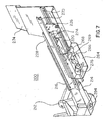
- Fig. 7 is shown the bottom view of the assembly 200 inclusive of foot side brackets 274.
- a foot mechanical lock 266 is fixed to foot lock housing 264 by two mechanical lock brackets 268 and 269.
- a mechanical lock rod 220 is rigidly screwed onto a thrust plate 226 of the assembly 200.
- mechanical lock solenoid 276 When mechanical lock solenoid 276 is activated, said foot mechanical lock 266 is released from mechanical lock rod 220, permitting foot-lock housing 264 to slide along the mechanical lock rod 220, thereby adjusting the overall length of the calf/foot support assembly 200 to accommodate different patient heights before the assembly is locked into position.
- hydraulic rod 221, spring assembly 224, thrust plate 226 and the entire foot side bracket group 260 (in Fig. 11 ), move in unison.
- Fig. 8 In the exploded view of Fig. 8 may be seen the front half of foot side brackets 274 and middle slides 228.
- hydraulic cylinder 218, is mounted inside of foot tubing 214, from which hydraulic rod 221 is powered.
- the other end of the hydraulic rod 221 is rigidly fixed into spring assembly 224 which in turn is mounted upon thrust plate 226.
- Said thrust plate 226 is itself mounted on middle slides 228 for hydraulic/pneumatic linear traction.
- Middle slides 228 slide upon outer slides 216.
- Fig. 9 is shown an exposed view of calf/foot support assembly 200 including, particularly, the foot tubing group 210 thereof. Foot tubing 214 may be seen, revealing hydraulic cylinder 218 which is located therein. Further shown is one of foot side brackets 274. It may be further seen that hydraulic rod 221 is connected to shock absorbing spring assembly 224 that is attached to thrust plate 226 which, in turn, is mounted upon middle slides 228 upon each side thereof. Inner slides 270 are fixed to the inside of foot side brackets 274. Outer slides 216 are externally attached to the sides of foot tubing 214. Middle slides 228 and inner slides 270 are indirectly locked by a mechanical lock in the foot lock housing 264 to insure transfer of hydraulic power to the foot side brackets. Also shown in Fig. 9 is load cell 219 which monitors over-pressure conditions at a proximal output of hydraulic cylinder 218, and vertical pivot axle 294 upon which foot tubing 214 rotates.
- calf/foot support assembly 200 including foot/calf support link casting 212, vertical pivot axle 294, foot tubing 214, transverse bar 215, ball-bearing slide assembly 232, foot lock housing 264, foot side brackets 274, and thrust plate 226.
- foot tubing 214 houses a foot traction hydraulic assembly (not shown) and pivots horizontally upon vertical pivot axle 294 of foot/calf support link casting 212.
- Ankle cushion, foot support assembly control bar (both not shown), and ankle harnesses mount on the foot side brackets and are slidably mounted upon foot tubing 214 by ball bearing slide assembly 232.
- a mechanical locking assembly is located inside of foot lock housing 264 and operates to unlock the main components of the foot assembly when patient height adjustment is required.
- Fig. 11 is shown foot tubing group 210 and foot side bracket group 260.
- the foot side bracket group 260 is pivotally attached to the foot support link casting 212 by vertical axial 294, and houses the foot traction hydraulic assembly inclusive of hydraulic cylinder 218, hydraulic rod 221 , and spring assembly 224.
- Foot side bracket group 260 is slidably attached to the foot tubing group 210 by means of said inner slides 270, middle slides 228, and outer slides 216. Individual adjustments to accommodate patients heights are made by allowing mechanical lock 266 to slide upon mechanical lock rod 220 , thus locking foot mechanical lock to the mechanical lock rod after an adjustment of relative position of foot side bracket group 260 to the hydraulic rod 220 of the foot tubing group 210.
- Fig. 12 which is related to Fig. 6 , is an illustration of the side-swing motion and side-swing assembly 290 of the calf/foot support assembly 200.
- calf/foot support assembly is pivotally attached to foot/calf support link casting 212 at vertical pivot axle 294 to effect sideway (left and right) movements of the calf and leg.
- the side-swing assembly (described more fully above in Fig. 6 ) links to foot tubing 214 through side swing control bar 292 which connects solenoid journal plate 299 of the side-swing assembly 290 to transverse bar 215 which rests upon ball bearing slide assembly 232. (See also Fig. 10 ).
- calf/foot support assembly control bar 209 As also shown in Fig. 12 are the controls associated with calf/foot support assembly control bar 209, namely, power traction Y axis control switches 300 and 302 as well as patient height, Y axis adjustment switch 304. Also shown in Fig. 12 is LCD reader 207, a foot rest 202, ankle cushion 204, and ankle strap brackets 203.
- Figs. 1 and 2 further illustrates a system control 74 for use by the doctor which includes the following function[[s]] buttons: 1.
- TBL LFT Table Lift. 2.
- TBL LWR Table Lower. 3.
- ROT BACK Rotate Table Back. 4.
- ROT FWD Rotate Table Forward. 5.
- ARM UP Translational Arm Height Up. 6.
- ARM DWN Translational Arm Height Down. 7.
- ARM R. UP Arm Rotate Up. 10.
- ARM R. DOWN Arm Rotate Down.
- LUM IN Lumbar In 12.
- LUM OUT Lumbar Out 13.
- RBK TL Rotate Table Back with Table Lift. 16.
- RFW TLW Rotate Table Forward with Table and Lower Table. 17.
- SAFETY ON AND OFF A safety on and off button is included which stops pneumatic/ hydraulic piston and ceases all table movement.
- controls may also be incorporated into overhead gripping means 54 or into handgrips 42 (see Figs. 1 and 2 ), with optional patient control of other functions.
Landscapes
- Health & Medical Sciences (AREA)
- Life Sciences & Earth Sciences (AREA)
- Public Health (AREA)
- Veterinary Medicine (AREA)
- Animal Behavior & Ethology (AREA)
- General Health & Medical Sciences (AREA)
- Biomedical Technology (AREA)
- Engineering & Computer Science (AREA)
- Rehabilitation Therapy (AREA)
- Physical Education & Sports Medicine (AREA)
- Pain & Pain Management (AREA)
- Epidemiology (AREA)
- Biophysics (AREA)
- Orthopedic Medicine & Surgery (AREA)
- Neurosurgery (AREA)
- Otolaryngology (AREA)
- Orthopedics, Nursing, And Contraception (AREA)
- Accommodation For Nursing Or Treatment Tables (AREA)
Applications Claiming Priority (2)
| Application Number | Priority Date | Filing Date | Title |
|---|---|---|---|
| US10/413,730 US6923825B2 (en) | 2000-09-13 | 2003-04-15 | Calf and foot support and adjustment assembly |
| PCT/US2004/011433 WO2004091467A2 (en) | 2003-04-15 | 2004-04-14 | Calf and foot support and adjustment assembly |
Publications (3)
| Publication Number | Publication Date |
|---|---|
| EP1617794A2 EP1617794A2 (en) | 2006-01-25 |
| EP1617794A4 EP1617794A4 (en) | 2007-10-24 |
| EP1617794B1 true EP1617794B1 (en) | 2012-09-12 |
Family
ID=33298375
Family Applications (1)
| Application Number | Title | Priority Date | Filing Date |
|---|---|---|---|
| EP04759515A Expired - Lifetime EP1617794B1 (en) | 2003-04-15 | 2004-04-14 | Calf and foot support and adjustment assembly |
Country Status (6)
| Country | Link |
|---|---|
| US (2) | US6923825B2 (https=) |
| EP (1) | EP1617794B1 (https=) |
| JP (1) | JP2006523512A (https=) |
| KR (1) | KR100979585B1 (https=) |
| CA (1) | CA2520953C (https=) |
| WO (1) | WO2004091467A2 (https=) |
Families Citing this family (21)
| Publication number | Priority date | Publication date | Assignee | Title |
|---|---|---|---|---|
| US6923825B2 (en) * | 2000-09-13 | 2005-08-02 | David F. Cuccia | Calf and foot support and adjustment assembly |
| US20080167684A1 (en) * | 2003-04-15 | 2008-07-10 | Cuccia David F | Treatment table with calf/foot assembly and method of use |
| US7951097B2 (en) * | 2009-06-15 | 2011-05-31 | Schaeffer Dwight L | Automated therapy table for treating lower extremities and method therefor |
| KR101054232B1 (ko) * | 2009-12-24 | 2011-08-08 | 한국산재의료원 | 자기유체제어식 척추굽힘운동 훈련기 |
| US20120078142A1 (en) * | 2010-03-25 | 2012-03-29 | Randall Fenkell | Continuous passive motion device |
| KR101415104B1 (ko) | 2012-03-05 | 2014-07-04 | 주식회사 씨에스테크놀로지 | 도수 치료용 테이블 |
| CN104027161A (zh) * | 2014-04-30 | 2014-09-10 | 陈春美 | 多向可调控体外复位髂腰垫 |
| KR101706587B1 (ko) * | 2014-12-04 | 2017-02-15 | 허강수 | 순차적 3단계 척추견인 기법을 이용한 척추견인장치 및 그 제어 방법,기록매체 |
| KR101706586B1 (ko) * | 2014-12-04 | 2017-02-27 | 허강수 | 3단계 척추견인 기법을 이용한 척추질환 치료장치 및 그 제어 방법, 기록매체 |
| US9616284B1 (en) * | 2016-08-25 | 2017-04-11 | Aganyan Inc. | Portable multi-functional upright body stretching apparatus |
| US9764188B1 (en) * | 2016-08-25 | 2017-09-19 | Aganyan Inc. | Portable multi-functional upright body stretching apparatus |
| CN107693182B (zh) * | 2016-10-14 | 2018-08-24 | 崔韡 | 一种护理用穿戴式牵引装置 |
| CN109172240B (zh) * | 2018-09-03 | 2020-11-17 | 张敏丽 | 腿部护理用支撑装置 |
| CN109620506B (zh) * | 2019-01-24 | 2024-04-09 | 河北医科大学第三医院 | 一种腰椎间盘突出牵引架 |
| US20220175605A1 (en) * | 2019-03-25 | 2022-06-09 | ScoliWRx Inc. | Systems and Methods for Relieving Nerve Tension in Scoliosis |
| CN111388253A (zh) * | 2020-03-26 | 2020-07-10 | 河北地质大学华信学院 | 一种可移动式妇产医疗车 |
| CN111904772A (zh) * | 2020-08-06 | 2020-11-10 | 张雷 | 一种骨科牵引架的多段双牙盘折叠式牵引腿杆机构 |
| CN112972192B (zh) * | 2021-03-02 | 2022-12-06 | 新疆维吾尔自治区人民医院 | 一种用于下肢康复治疗的辅助用具 |
| CN115517875B (zh) * | 2022-04-13 | 2024-10-29 | 云阳县江口镇中心卫生院(云阳县第二人民医院) | 一种儿科腿部骨折术后护理床 |
| CN117919013B (zh) * | 2024-03-11 | 2024-07-09 | 中国人民解放军联勤保障部队第九二四医院 | 一种基于气囊的下肢康复运动装置 |
| CN119454362B (zh) * | 2024-11-26 | 2025-10-17 | 中国人民解放军陆军特色医学中心 | 一种照护轮椅机器人及照护方法 |
Family Cites Families (14)
| Publication number | Priority date | Publication date | Assignee | Title |
|---|---|---|---|---|
| US2023429A (en) * | 1934-05-21 | 1935-12-10 | Williams Mfg Company Inc | Chiropractic table |
| US2273088A (en) * | 1940-01-03 | 1942-02-17 | Byers George | Massaging table |
| US2267054A (en) * | 1940-10-17 | 1941-12-23 | Williams Mfg Company | Chiropractic table |
| US3060926A (en) * | 1961-02-06 | 1962-10-30 | William E Westcott | Therapeutic table |
| US3238936A (en) * | 1962-04-16 | 1966-03-08 | Nat Foundation For Physical Me | Apparatus for mechanical corrective therapy |
| US4582311A (en) | 1983-10-27 | 1986-04-15 | Steffensmeier Lloyd A | Hydraulically controlled chiropractic table |
| JPH0339967U (https=) * | 1989-08-28 | 1991-04-17 | ||
| US5176706A (en) * | 1991-09-06 | 1993-01-05 | Lee Jong W | Spinal curvature correction device |
| US5794286A (en) * | 1995-09-13 | 1998-08-18 | Standex International | Patient treatment apparatus |
| US5860899A (en) * | 1996-10-07 | 1999-01-19 | New Back Technologies, L.L.C. | Back manipulating apparatus |
| US5840001A (en) * | 1997-03-24 | 1998-11-24 | Schedel; Robert M. | Therapy exercise table |
| JP3583005B2 (ja) * | 1999-02-23 | 2004-10-27 | 維衛 川合 | 腰痛治療機 |
| US6547809B1 (en) * | 1999-09-14 | 2003-04-15 | David F. Cuccia | Multi-function chiropractic treatment table |
| US6923825B2 (en) * | 2000-09-13 | 2005-08-02 | David F. Cuccia | Calf and foot support and adjustment assembly |
-
2003
- 2003-04-15 US US10/413,730 patent/US6923825B2/en not_active Expired - Fee Related
-
2004
- 2004-04-14 KR KR1020057019314A patent/KR100979585B1/ko not_active Expired - Fee Related
- 2004-04-14 CA CA002520953A patent/CA2520953C/en not_active Expired - Fee Related
- 2004-04-14 WO PCT/US2004/011433 patent/WO2004091467A2/en not_active Ceased
- 2004-04-14 EP EP04759515A patent/EP1617794B1/en not_active Expired - Lifetime
- 2004-04-14 JP JP2006510007A patent/JP2006523512A/ja active Pending
-
2005
- 2005-07-25 US US11/189,956 patent/US7309347B2/en not_active Expired - Fee Related
Also Published As
| Publication number | Publication date |
|---|---|
| JP2006523512A (ja) | 2006-10-19 |
| CA2520953A1 (en) | 2004-10-28 |
| CA2520953C (en) | 2009-12-22 |
| KR100979585B1 (ko) | 2010-09-01 |
| US6923825B2 (en) | 2005-08-02 |
| EP1617794A4 (en) | 2007-10-24 |
| WO2004091467A2 (en) | 2004-10-28 |
| KR20060023523A (ko) | 2006-03-14 |
| US20030216782A1 (en) | 2003-11-20 |
| EP1617794A2 (en) | 2006-01-25 |
| WO2004091467A3 (en) | 2005-06-30 |
| US20050256538A1 (en) | 2005-11-17 |
| US7309347B2 (en) | 2007-12-18 |
Similar Documents
| Publication | Publication Date | Title |
|---|---|---|
| EP1617794B1 (en) | Calf and foot support and adjustment assembly | |
| US12097151B2 (en) | Surgical table and accessories to facilitate hip arthroscopy | |
| US4915101A (en) | Rotatable treatment table having adjustable support assemblies | |
| US6547809B1 (en) | Multi-function chiropractic treatment table | |
| CN110996871B (zh) | 包含用于便于接近患者的主梁的手术支架 | |
| US10888484B2 (en) | Reconfigurable pelvic support for surgical frame and method for use thereof | |
| CN107920946B (zh) | 促进在手术期间对患者的关节式支撑的手术支架 | |
| US10881570B2 (en) | Reconfigurable pelvic support for a surgical frame and method for use thereof | |
| US6905508B2 (en) | Lumbar support and adjustment assembly | |
| US20250367052A1 (en) | Reconfigurable upper leg support for a surgical frame | |
| JP2006523512A5 (https=) | ||
| WO2017031225A1 (en) | Surgical frame facilitating articulatable support for a patient during surgery | |
| US5922011A (en) | Multi-function chiropractic treatment table | |
| US20080167684A1 (en) | Treatment table with calf/foot assembly and method of use | |
| WO2007027573A2 (en) | Lumbar lordosis brace | |
| RU2348391C1 (ru) | Кровать медицинская функциональная | |
| CA2374259C (en) | Multi-function chiropractic treatment table | |
| CN118319572A (zh) | 一种腰椎曲度及骨盆矫正仪器 |
Legal Events
| Date | Code | Title | Description |
|---|---|---|---|
| PUAI | Public reference made under article 153(3) epc to a published international application that has entered the european phase |
Free format text: ORIGINAL CODE: 0009012 |
|
| 17P | Request for examination filed |
Effective date: 20051105 |
|
| AK | Designated contracting states |
Kind code of ref document: A2 Designated state(s): AT BE BG CH CY CZ DE DK EE ES FI FR GB GR HU IE IT LI LU MC NL PL PT RO SE SI SK TR |
|
| AX | Request for extension of the european patent |
Extension state: AL HR LT LV MK |
|
| DAX | Request for extension of the european patent (deleted) | ||
| A4 | Supplementary search report drawn up and despatched |
Effective date: 20070926 |
|
| RIC1 | Information provided on ipc code assigned before grant |
Ipc: A61G 13/00 20060101AFI20070920BHEP Ipc: A61H 1/02 20060101ALI20070920BHEP |
|
| 17Q | First examination report despatched |
Effective date: 20080307 |
|
| RIC1 | Information provided on ipc code assigned before grant |
Ipc: A61H 1/02 20060101ALI20111214BHEP Ipc: A61G 13/00 20060101AFI20111214BHEP Ipc: A61G 13/12 20060101ALI20111214BHEP |
|
| GRAP | Despatch of communication of intention to grant a patent |
Free format text: ORIGINAL CODE: EPIDOSNIGR1 |
|
| GRAS | Grant fee paid |
Free format text: ORIGINAL CODE: EPIDOSNIGR3 |
|
| GRAA | (expected) grant |
Free format text: ORIGINAL CODE: 0009210 |
|
| AK | Designated contracting states |
Kind code of ref document: B1 Designated state(s): AT BE BG CH CY CZ DE DK EE ES FI FR GB GR HU IE IT LI LU MC NL PL PT RO SE SI SK TR |
|
| REG | Reference to a national code |
Ref country code: GB Ref legal event code: FG4D |
|
| REG | Reference to a national code |
Ref country code: CH Ref legal event code: EP |
|
| REG | Reference to a national code |
Ref country code: AT Ref legal event code: REF Ref document number: 574688 Country of ref document: AT Kind code of ref document: T Effective date: 20120915 |
|
| REG | Reference to a national code |
Ref country code: IE Ref legal event code: FG4D |
|
| REG | Reference to a national code |
Ref country code: DE Ref legal event code: R096 Ref document number: 602004039308 Country of ref document: DE Effective date: 20121108 |
|
| PG25 | Lapsed in a contracting state [announced via postgrant information from national office to epo] |
Ref country code: FI Free format text: LAPSE BECAUSE OF FAILURE TO SUBMIT A TRANSLATION OF THE DESCRIPTION OR TO PAY THE FEE WITHIN THE PRESCRIBED TIME-LIMIT Effective date: 20120912 |
|
| REG | Reference to a national code |
Ref country code: NL Ref legal event code: VDEP Effective date: 20120912 |
|
| REG | Reference to a national code |
Ref country code: AT Ref legal event code: MK05 Ref document number: 574688 Country of ref document: AT Kind code of ref document: T Effective date: 20120912 |
|
| PG25 | Lapsed in a contracting state [announced via postgrant information from national office to epo] |
Ref country code: SI Free format text: LAPSE BECAUSE OF FAILURE TO SUBMIT A TRANSLATION OF THE DESCRIPTION OR TO PAY THE FEE WITHIN THE PRESCRIBED TIME-LIMIT Effective date: 20120912 Ref country code: SE Free format text: LAPSE BECAUSE OF FAILURE TO SUBMIT A TRANSLATION OF THE DESCRIPTION OR TO PAY THE FEE WITHIN THE PRESCRIBED TIME-LIMIT Effective date: 20120912 |
|
| REG | Reference to a national code |
Ref country code: GR Ref legal event code: EP Ref document number: 20120402777 Country of ref document: GR Effective date: 20130205 |
|
| PG25 | Lapsed in a contracting state [announced via postgrant information from national office to epo] |
Ref country code: CZ Free format text: LAPSE BECAUSE OF FAILURE TO SUBMIT A TRANSLATION OF THE DESCRIPTION OR TO PAY THE FEE WITHIN THE PRESCRIBED TIME-LIMIT Effective date: 20120912 Ref country code: BE Free format text: LAPSE BECAUSE OF FAILURE TO SUBMIT A TRANSLATION OF THE DESCRIPTION OR TO PAY THE FEE WITHIN THE PRESCRIBED TIME-LIMIT Effective date: 20120912 Ref country code: EE Free format text: LAPSE BECAUSE OF FAILURE TO SUBMIT A TRANSLATION OF THE DESCRIPTION OR TO PAY THE FEE WITHIN THE PRESCRIBED TIME-LIMIT Effective date: 20120912 Ref country code: NL Free format text: LAPSE BECAUSE OF FAILURE TO SUBMIT A TRANSLATION OF THE DESCRIPTION OR TO PAY THE FEE WITHIN THE PRESCRIBED TIME-LIMIT Effective date: 20120912 Ref country code: RO Free format text: LAPSE BECAUSE OF FAILURE TO SUBMIT A TRANSLATION OF THE DESCRIPTION OR TO PAY THE FEE WITHIN THE PRESCRIBED TIME-LIMIT Effective date: 20120912 Ref country code: ES Free format text: LAPSE BECAUSE OF FAILURE TO SUBMIT A TRANSLATION OF THE DESCRIPTION OR TO PAY THE FEE WITHIN THE PRESCRIBED TIME-LIMIT Effective date: 20121223 |
|
| PG25 | Lapsed in a contracting state [announced via postgrant information from national office to epo] |
Ref country code: PL Free format text: LAPSE BECAUSE OF FAILURE TO SUBMIT A TRANSLATION OF THE DESCRIPTION OR TO PAY THE FEE WITHIN THE PRESCRIBED TIME-LIMIT Effective date: 20120912 Ref country code: SK Free format text: LAPSE BECAUSE OF FAILURE TO SUBMIT A TRANSLATION OF THE DESCRIPTION OR TO PAY THE FEE WITHIN THE PRESCRIBED TIME-LIMIT Effective date: 20120912 Ref country code: PT Free format text: LAPSE BECAUSE OF FAILURE TO SUBMIT A TRANSLATION OF THE DESCRIPTION OR TO PAY THE FEE WITHIN THE PRESCRIBED TIME-LIMIT Effective date: 20130114 |
|
| PG25 | Lapsed in a contracting state [announced via postgrant information from national office to epo] |
Ref country code: AT Free format text: LAPSE BECAUSE OF FAILURE TO SUBMIT A TRANSLATION OF THE DESCRIPTION OR TO PAY THE FEE WITHIN THE PRESCRIBED TIME-LIMIT Effective date: 20120912 |
|
| PLBE | No opposition filed within time limit |
Free format text: ORIGINAL CODE: 0009261 |
|
| STAA | Information on the status of an ep patent application or granted ep patent |
Free format text: STATUS: NO OPPOSITION FILED WITHIN TIME LIMIT |
|
| PG25 | Lapsed in a contracting state [announced via postgrant information from national office to epo] |
Ref country code: BG Free format text: LAPSE BECAUSE OF FAILURE TO SUBMIT A TRANSLATION OF THE DESCRIPTION OR TO PAY THE FEE WITHIN THE PRESCRIBED TIME-LIMIT Effective date: 20121212 Ref country code: DK Free format text: LAPSE BECAUSE OF FAILURE TO SUBMIT A TRANSLATION OF THE DESCRIPTION OR TO PAY THE FEE WITHIN THE PRESCRIBED TIME-LIMIT Effective date: 20120912 |
|
| 26N | No opposition filed |
Effective date: 20130613 |
|
| PG25 | Lapsed in a contracting state [announced via postgrant information from national office to epo] |
Ref country code: IT Free format text: LAPSE BECAUSE OF FAILURE TO SUBMIT A TRANSLATION OF THE DESCRIPTION OR TO PAY THE FEE WITHIN THE PRESCRIBED TIME-LIMIT Effective date: 20120912 |
|
| REG | Reference to a national code |
Ref country code: DE Ref legal event code: R097 Ref document number: 602004039308 Country of ref document: DE Effective date: 20130613 |
|
| PG25 | Lapsed in a contracting state [announced via postgrant information from national office to epo] |
Ref country code: MC Free format text: LAPSE BECAUSE OF FAILURE TO SUBMIT A TRANSLATION OF THE DESCRIPTION OR TO PAY THE FEE WITHIN THE PRESCRIBED TIME-LIMIT Effective date: 20120912 |
|
| REG | Reference to a national code |
Ref country code: CH Ref legal event code: PL |
|
| GBPC | Gb: european patent ceased through non-payment of renewal fee |
Effective date: 20130414 |
|
| REG | Reference to a national code |
Ref country code: GR Ref legal event code: ML Ref document number: 20120402777 Country of ref document: GR Effective date: 20131104 |
|
| REG | Reference to a national code |
Ref country code: IE Ref legal event code: MM4A |
|
| PG25 | Lapsed in a contracting state [announced via postgrant information from national office to epo] |
Ref country code: LI Free format text: LAPSE BECAUSE OF NON-PAYMENT OF DUE FEES Effective date: 20130430 Ref country code: DE Free format text: LAPSE BECAUSE OF NON-PAYMENT OF DUE FEES Effective date: 20131101 Ref country code: CY Free format text: LAPSE BECAUSE OF FAILURE TO SUBMIT A TRANSLATION OF THE DESCRIPTION OR TO PAY THE FEE WITHIN THE PRESCRIBED TIME-LIMIT Effective date: 20130703 Ref country code: GB Free format text: LAPSE BECAUSE OF NON-PAYMENT OF DUE FEES Effective date: 20130414 Ref country code: CH Free format text: LAPSE BECAUSE OF NON-PAYMENT OF DUE FEES Effective date: 20130430 |
|
| REG | Reference to a national code |
Ref country code: FR Ref legal event code: ST Effective date: 20131231 |
|
| REG | Reference to a national code |
Ref country code: DE Ref legal event code: R119 Ref document number: 602004039308 Country of ref document: DE Effective date: 20131101 |
|
| PG25 | Lapsed in a contracting state [announced via postgrant information from national office to epo] |
Ref country code: FR Free format text: LAPSE BECAUSE OF NON-PAYMENT OF DUE FEES Effective date: 20130430 Ref country code: GR Free format text: LAPSE BECAUSE OF NON-PAYMENT OF DUE FEES Effective date: 20131104 |
|
| PG25 | Lapsed in a contracting state [announced via postgrant information from national office to epo] |
Ref country code: CY Free format text: LAPSE BECAUSE OF FAILURE TO SUBMIT A TRANSLATION OF THE DESCRIPTION OR TO PAY THE FEE WITHIN THE PRESCRIBED TIME-LIMIT Effective date: 20130414 |
|
| PG25 | Lapsed in a contracting state [announced via postgrant information from national office to epo] |
Ref country code: IE Free format text: LAPSE BECAUSE OF NON-PAYMENT OF DUE FEES Effective date: 20130414 |
|
| PG25 | Lapsed in a contracting state [announced via postgrant information from national office to epo] |
Ref country code: TR Free format text: LAPSE BECAUSE OF FAILURE TO SUBMIT A TRANSLATION OF THE DESCRIPTION OR TO PAY THE FEE WITHIN THE PRESCRIBED TIME-LIMIT Effective date: 20120912 |
|
| PG25 | Lapsed in a contracting state [announced via postgrant information from national office to epo] |
Ref country code: LU Free format text: LAPSE BECAUSE OF NON-PAYMENT OF DUE FEES Effective date: 20130414 Ref country code: HU Free format text: LAPSE BECAUSE OF FAILURE TO SUBMIT A TRANSLATION OF THE DESCRIPTION OR TO PAY THE FEE WITHIN THE PRESCRIBED TIME-LIMIT; INVALID AB INITIO Effective date: 20040414 |