EP1617583A1 - Radio transmitting/receiving apparatus and radio transmitting/receiving method for estimating noise and interference power in ratio transmission using code spread - Google Patents
Radio transmitting/receiving apparatus and radio transmitting/receiving method for estimating noise and interference power in ratio transmission using code spread Download PDFInfo
- Publication number
- EP1617583A1 EP1617583A1 EP04729507A EP04729507A EP1617583A1 EP 1617583 A1 EP1617583 A1 EP 1617583A1 EP 04729507 A EP04729507 A EP 04729507A EP 04729507 A EP04729507 A EP 04729507A EP 1617583 A1 EP1617583 A1 EP 1617583A1
- Authority
- EP
- European Patent Office
- Prior art keywords
- code
- spreading
- despreading
- time axis
- frequency axis
- Prior art date
- Legal status (The legal status is an assumption and is not a legal conclusion. Google has not performed a legal analysis and makes no representation as to the accuracy of the status listed.)
- Withdrawn
Links
Images


Classifications
-
- H—ELECTRICITY
- H04—ELECTRIC COMMUNICATION TECHNIQUE
- H04B—TRANSMISSION
- H04B1/00—Details of transmission systems, not covered by a single one of groups H04B3/00 - H04B13/00; Details of transmission systems not characterised by the medium used for transmission
- H04B1/69—Spread spectrum techniques
- H04B1/692—Hybrid techniques using combinations of two or more spread spectrum techniques
-
- H—ELECTRICITY
- H04—ELECTRIC COMMUNICATION TECHNIQUE
- H04L—TRANSMISSION OF DIGITAL INFORMATION, e.g. TELEGRAPHIC COMMUNICATION
- H04L5/00—Arrangements affording multiple use of the transmission path
- H04L5/02—Channels characterised by the type of signal
- H04L5/023—Multiplexing of multicarrier modulation signals, e.g. multi-user orthogonal frequency division multiple access [OFDMA]
- H04L5/026—Multiplexing of multicarrier modulation signals, e.g. multi-user orthogonal frequency division multiple access [OFDMA] using code division
-
- H—ELECTRICITY
- H04—ELECTRIC COMMUNICATION TECHNIQUE
- H04B—TRANSMISSION
- H04B1/00—Details of transmission systems, not covered by a single one of groups H04B3/00 - H04B13/00; Details of transmission systems not characterised by the medium used for transmission
- H04B1/69—Spread spectrum techniques
- H04B1/707—Spread spectrum techniques using direct sequence modulation
- H04B1/7097—Interference-related aspects
-
- H—ELECTRICITY
- H04—ELECTRIC COMMUNICATION TECHNIQUE
- H04J—MULTIPLEX COMMUNICATION
- H04J11/00—Orthogonal multiplex systems, e.g. using WALSH codes
- H04J11/0023—Interference mitigation or co-ordination
- H04J11/0026—Interference mitigation or co-ordination of multi-user interference
- H04J11/0036—Interference mitigation or co-ordination of multi-user interference at the receiver
-
- H—ELECTRICITY
- H04—ELECTRIC COMMUNICATION TECHNIQUE
- H04J—MULTIPLEX COMMUNICATION
- H04J13/00—Code division multiplex systems
- H04J13/0007—Code type
- H04J13/004—Orthogonal
-
- H—ELECTRICITY
- H04—ELECTRIC COMMUNICATION TECHNIQUE
- H04J—MULTIPLEX COMMUNICATION
- H04J13/00—Code division multiplex systems
- H04J13/16—Code allocation
- H04J13/18—Allocation of orthogonal codes
-
- H—ELECTRICITY
- H04—ELECTRIC COMMUNICATION TECHNIQUE
- H04L—TRANSMISSION OF DIGITAL INFORMATION, e.g. TELEGRAPHIC COMMUNICATION
- H04L27/00—Modulated-carrier systems
- H04L27/26—Systems using multi-frequency codes
- H04L27/2601—Multicarrier modulation systems
- H04L27/2602—Signal structure
- H04L27/261—Details of reference signals
- H04L27/2613—Structure of the reference signals
Definitions
- the present invention relates to a radio transmitter-receiver and a radio transmitting-receiving method that estimates noise and interference power in radio transmission that uses code spreading.
- Radio transmission systems of the prior art include radio transmission systems of the CDMA (Code Division Multiple Access)/TDD (Time Division Duplex) method that suppress the transmission power control error to a low level at mobile stations when diversity reception is performed by means of a plurality of antennas at a base station (For example, refer to Patent Document 1).
- CDMA Code Division Multiple Access
- TDD Time Division Duplex
- communication devices of the OFDM-CDMA method also exist that prevent deterioration of the error rate characteristic of a demodulated signal without impairing transmission efficiency (for example, refer to Patent
- Multicarrier transmission devices of the multicarrier CDMA method also exist that neither require a broad frequency band nor cause high peaks in the signal waveform (for example, refer to Patent Document 5).
- OFDM communication devices that arrange information signals that have undergone direct sequence spreading in DS subcarriers to improve the transmission efficiency while suppressing the error rate characteristic of information signals (for example, refer to Patent Document 6).
- Cellular spread-spectrum communication systems also exist in which each terminal device can communicate with a base station at a high S/N and that can increase the number of simultaneous communications in each cell (for example, refer to Patent Document 7).
- OFDM-CDMA radio communication devices also exist that can prevent both increase in peak power and deterioration of communication quality (for example, refer to Patent Document 8).
- noise and interference power are estimated by despreading the received signal by means of a spreading code that is not used in spreading the pilot signal.
- This explanation takes a case in which spreading codes that are spread on the time axis at spreading rate 4 as shown in FIG. 1.
- pilot signal is used that is spread two chips on the time axis and two chips on the frequency axis at a spreading rate 4 as shown in FIG. 2.
- a case is here considered in which the three codes Code 1, Code 2, and Code 3 are used to spread the pilot signal, and noise and interference power are estimated by despreading the received signal by Code 4.
- the channel impulse response values that correspond to C 0 , C 1 , C 2 , and C 3 of FIG. 2 are h 11 , h 21 , h 12 , and h 22 , respectively; and the noise and interference components are Nl 11, Nl 21 , Nl 12 , and Nl 22 .
- the problem occurs that, when the noise and interference power estimation method that is conventionally used in the above-described CDMA is applied without alteration to a pilot signal that is subjected to two-dimensional spreading as described above, the estimation accuracy deteriorates dramatically if the channel fluctuation on both the frequency axis and the time axis is not sufficiently low. For example, even when fluctuation on the time axis is almost absent, i.e., even when: h 11 ⁇ h 12 and h 21 ⁇ h 22 then d is: d ⁇ 2 h 11 - 2 h 21 + NI 11 - NI 21 - NI 12 + NI 22 and if the fluctuation on the frequency axis is great, i.e.
- the spreading code that is not used in spreading the pilot signal is used as a despreading code to despread the received signal and then estimate the noise and interference power
- the spreading code that is used in spreading the pilot symbol and the despreading code that is used in despreading are assigned so as to be orthogonal even if only in N chips on the time axis.
- the second radio transmitter-receiver in a case in which a pilot symbol that has undergone M-chip spreading on the frequency axis and N-chip spreading on the time axis by means of a spreading code having an M ⁇ N chip length (where M and N are any integers that are greater than or equal to 2) is used in the transmitter, and in the receiver, a spreading code that is not used in spreading the pilot signal is used as a despreading code to despread the received signal and then estimate the noise and interference power, the spreading code that is used in spreading the pilot symbol and the despreading code that is used in despreading are assigned so as to be orthogonal even if only in M chips on the frequency axis.
- the third radio transmitter-receiver in a case in which a pilot symbol that has undergone M-chip spreading on the frequency axis and N-chip spreading on the time axis by means of a spreading code having an M ⁇ N chip length (where M and N are any integers that are greater than or equal to 2) is used in the transmitter, and in the receiver, a spreading code that is not used in spreading the pilot signal is used as a despreading code to despread the received signal and then estimate the noise and interference power, the spreading code that is used in spreading the pilot symbol and the despreading code that is used in despreading are assigned either to be orthogonal even if only in M chips on the frequency axis or to be orthogonal even if only in N chips on the time axis.
- the fourth radio transmitter-receiver in a case in which a pilot symbol that has undergone M-chip spreading on the frequency axis and N-chip spreading on the time axis by means of a spreading code having an M ⁇ N chip length (where M and N are any integers that are greater than or equal to 2) is used in the transmitter, and in the receiver, a spreading code that is not used in spreading the pilot signal is used as a despreading code to despread the received signal and then estimate the noise and interference power, code that is orthogonal to the despreading code that is used in despreading even if only in N chips on the time axis is preferentially assigned as a spreading code that is used in spreading pilot symbols.
- the fifth radio transmitter-receiver in a case in which a pilot symbol that has undergone M-chip spreading on the frequency axis and N-chip spreading on the time axis by means of a spreading code having an M ⁇ N chip length (where M and N are any integers that are greater than or equal to 2) is used in the transmitter, and in the receiver, a spreading code that is not used in spreading the pilot signal is used as a despreading code to despread the received signal and then estimate the noise and interference power, code that is orthogonal to the despreading code that is used in despreading even if only in M chips on the frequency axis is preferentially assigned as the spreading code that is used in spreading pilot symbols.
- the sixth radio transmitter-receiver in a case in which a pilot symbol that has undergone M-chip spreading on the frequency axis and N-chip spreading on the time axis by means of a spreading code having an M ⁇ N chip length (where M and N are any integers that are greater than or equal to 2) is used in the transmitter, and in the receiver, a spreading code that is not used in spreading the pilot signal is used as a despreading code to despread the received signal and the noise and interference power then estimated, code that is orthogonal to the despreading code that is used in despreading even if only in M chips on the frequency axis, and further, orthogonal even if only in N chips on the time axis is preferentially assigned as spreading code that is used in spreading pilot symbols.
- the seventh radio transmitter-receiver in a case in which a pilot symbol that has undergone M-chip spreading on the frequency axis and N-chip spreading on the time axis by means of a spreading code having an M ⁇ N chip length (where M and N are any integers that are greater than or equal to 2) is used in the transmitter, and in the receiver, a spreading code that is not used in spreading the pilot signal is used as a despreading code to despread the received signal and then estimate the noise and interference power, includes in the receiver: means for detecting whether either of channel fluctuation on the frequency axis and channel fluctuation on the time axis is prominent, and means for reporting the detection results to a transmitter; and when channel fluctuation on the time axis is prominent, assigns as spreading code that is used in spreading a pilot symbol code that is orthogonal to the despreading code that is used in despreading even if only in M chips on the frequency axis; and assigns as spreading code that is used in spreading a pilot symbol
- the eighth radio transmitter-receiver provided by the present invention in a case in which a pilot symbol that has undergone M-chip spreading on the frequency axis and N-chip spreading on the time axis by means of a spreading code having an M ⁇ N chip length (where M and N are any integers that are greater than or equal to 2) is used in the transmitter, and in the receiver, a spreading code that is not used in spreading the pilot signal is used as a despreading code to despread the received signal and then estimate noise and interference power, includes in the transmitter: means for detecting whether either of channel fluctuation on the frequency axis and channel fluctuation on the time axis is prominent; and assigns, as the spreading code that is used in spreading a pilot symbol, code that is orthogonal to the despreading code that is used in despreading even if only in M chips on the frequency axis when channel fluctuation on the time axis is prominent; and assigns, as spreading code that is used in spreading a pilot symbol, code that is orthogonal to the despre
- the ninth radio transmitter-receiver in a case in which a pilot symbol that has undergone M-chip spreading on the frequency axis and N-chip spreading on the time axis by means of a spreading code having an M ⁇ N chip length (where M and N are any integers that are greater than or equal to 2) is used in the transmitter, and in the receiver, a spreading code that is not used in spreading the pilot signal is used as a despreading code to despread the received signal and then estimate noise and interference power, includes in the receiver: means for detecting whether either of channel fluctuation on the frequency axis and channel fluctuation on the time axis is prominent and means for reporting the detection results to the transmitter; and when channel fluctuation on the time axis is prominent, preferentially assigns, as spreading code that is used in spreading the pilot symbol, code that is orthogonal to the despreading code that is used in despreading even if only in M chips on the frequency axis; and when channel fluctuation on the frequency axis is prominent,
- the tenth radio transmitter-receiver provided by the present invention in a case in which a pilot symbol that has undergone M-chip spreading on the frequency axis and N-chip spreading on the time axis by means of a spreading code having an M ⁇ N chip length (where M and N are any integers that are greater than or equal to 2) is used in the transmitter, and in the receiver, a spreading code that is not used in spreading the pilot signal is used as a despreading code to despread the received signal and then estimate the noise and interference power, includes in the transmitter: means for detecting whether either of channel fluctuation on the frequency axis and channel fluctuation on the time axis is prominent; and when channel fluctuation on the time axis is prominent, preferentially assigns, as spreading code that is used in spreading the pilot symbol, code that is orthogonal to the despreading code that is used in despreading even if only in M chips on the frequency axis; and when channel fluctuation on the frequency axis is prominent, preferentially assigns, as
- a delay spread may be used as an index of the channel fluctuation on the frequency axis.
- a coherent band may be used as an index of the channel fluctuation on the frequency axis.
- a Doppler frequency may be used as an index of channel fluctuation on the time axis.
- the radio transmitter-receiver of the present invention is thus capable of realizing highly accurate noise and interference power estimation even when either the channel fluctuation on the frequency axis or channel fluctuation on the time axis is great.
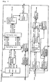
- FIG. 3 is a block diagram showing the configuration of a radio transmitter-receiver in the first embodiment according to the present invention.
- a pilot signal is of course multiplexed with data and transmitted in the transmitter and a means for demodulating the data is necessary in the receiver, but for the sake of simplification, explanation here will focus on only the transmission and reception of the pilot signal.
- a pilot signal is used that is spread at spreading rate 4 on two chips on the frequency axis and two chips on the time axis.
- data copy unit 103 makes four copies of pilot signal S PI and supplies this output as parallel pilot signals S PPI (1)-S PPI (4).
- Parallel/serial converter 104 effects parallel/serial conversion of parallel pilot signals S PPI (1)-S PPI (4) and supplies direct spread input signals S SPI (1), S SPI (2), S SPI (3), and S SPI (4) as output.
- Spreading code assignment unit 105 supplies spreading code assignment signal S CAL as output.
- Spreading unit 106 receives as input direct spread input signals S SPI (1), S SPI (2), S SPI (3), and S SPI (4) and spreading code assignment signal S CAL , and supplies as output first direct spreading output signals S SPO1 (1), S SPO1 (2), S SPO1 (3), and S SPO1 (4) and second direct spreading output signals S SPO2 (1), S SPO2 (2), S SPO2 (3), and S SPO2 (4).
- Multiplex unit 107 performs code multiplexing of first direct spreading output signals S SPO1 (1), S SPO1 (2), S SPO1 (3), and S SPO1 (4) and second direct spreading output signals S SPO2 (1), S SPO2 (2), S SPO2 (3), and S SPO2 (4), and supplies output as IFFT input signals S IFFTI (1), S IFFTI (2), S IFFTI (3), and S IFFTI (4).
- Inverse Fourier transform unit 108 performs inverse Fourier transformation of IFFT input signals S IFFTI (1), S IFFTI (2), S IFFTI (3), and S IFFTI (4), and supplies output as IFFT output signals S IFFTO (1), S IFFO (2), S IFFTO (3), and S IFFTO (4).
- Guard interval adder 109 adds a guard interval to IFFT output signals S IFFTO (1), S IFFTO (2), S IFFTO (3), and S IFFTO (4), and supplies output as transmission signals S TX (1), S TX (2), S TX (3), and S TX (4).
- guard interval elimination unit 110 removes the guard interval from received signals S RX (1), S RX (2), S RX (3), and S RX (4), and supplies as output FFT input signals S FFTI (1), S FFTI (2), S FFTI (3), and S FFTI (4).
- Fourier transform unit 111 performs Fourier transformation of FFT input signals S FFTI (1), S FFTI (2), S FFTI (3), and S FFTI (4) and supplies as output FFT output signals S FFTO (1), S FFTO (2), S FFTO (3), and S FFTO (4).
- Parallel/serial conversion unit 112 performs parallel/serial conversion of FFT output signals S FFTO (1), S FFTO (2), S FFTO (3), and S FFTO (4) and supplies as output despreading input signals S DSPI (1), S DSPI (2), S DSPI (3), and S DSPI (4).
- Despreading code assignment unit 113 supplies despreading code assignment signal S DCAL as output.
- Despreading unit 114 receives as input despreading input signals S DSPI (1), S DSPI (2), S DSPI (3), and S DSPI (4) and despreading code assignment signal S DCAL and supplies as output despreading output signal S DSPO .
- Power calculation unit 115 receives despreading output signal S DSPO as input, estimates the noise and interference power, and supplies an estimated power signal as output.
- the estimation of noise and interference power is realized by the above-described operations.
- the two spreading codes that are assigned by spreading code assignment unit 105 are orthogonal to the despreading code that is assigned by despreading code assignment unit 113 even if only on the time axis.
- a pilot signal that is spread two chips on the frequency axis and two chips on the time axis at the spread rate 4 as shown in FIG. 2 is now employed.
- this radio transmitter-receiver is identical to that of the first embodiment, this configuration is shown by the block diagram of FIG. 3.
- the second embodiment and the first embodiment differ in that the two spreading codes that are assigned by spreading code assignment unit 105 are orthogonal to the despreading code that is assigned by despreading code assignment unit 113 even if only on the frequency axis. It is now assumed that a pilot signal is used that has been spread two chips on the frequency axis and two chips on the time axis by means of a spreading rate 4 as shown in FIG. 2.
- the third embodiment differs from the first and second embodiments in that the spreading code that is assigned by spreading code assignment unit 105 is orthogonal to the despreading code that is assigned by despreading code assignment unit 113 even if only on the frequency axis and only the time axis. It is now assumed that a pilot signal is used that has been spread two chips on the frequency axis and two chips on the time axis at a spreading rate 4 as shown in FIG. 2.
- FIG. 4 is a block diagram showing the configuration of a radio transmitter-receiver in the fourth embodiment of the present invention. As the points of difference between this figure and FIG. 3, which is the block diagram in the first to third embodiments:
- Assignment is realized in despreading code assignment unit 207 based on channel fluctuation information S CHl and in spreading code assignment unit 204 based on reproduction channel fluctuation information S RECHl that has reproduced channel fluctuation information S CHl such that the spreading code and despreading code are orthogonal even if only in M chips on the frequency axis when channel fluctuation on the time axis is greater than fluctuation on the frequency axis and such that the spreading code and despreading code are orthogonal even if only in N chips on the time axis when channel fluctuation on the frequency axis is greater than fluctuation on the time axis.
- code assignment can be realized in accordance with channel fluctuation to enable greater accuracy in noise and interference power estimation.
Landscapes
- Engineering & Computer Science (AREA)
- Signal Processing (AREA)
- Computer Networks & Wireless Communication (AREA)
- Mobile Radio Communication Systems (AREA)
- Noise Elimination (AREA)
Abstract
Description
- The present invention relates to a radio transmitter-receiver and a radio transmitting-receiving method that estimates noise and interference power in radio transmission that uses code spreading.
- Radio transmission systems of the prior art include radio transmission systems of the CDMA (Code Division Multiple Access)/TDD (Time Division Duplex) method that suppress the transmission power control error to a low level at mobile stations when diversity reception is performed by means of a plurality of antennas at a base station (For example, refer to Patent Document 1).
- Alternatively, in OFDM (Orthogonal Frequency Division Multiplexing)-CDMA communication, there are transmitter-receivers that reduce the difference in amplitudes between subcarriers and maintain orthogonality between spreading codes to improve the transmission efficiency in a mum-path environment (for example, refer to Patent Document 2).
- As another example, there are also communication terminal devices of the OFDM-CDMA method that compensate for residual phase errors (for example, refer to Patent Document 3).
- In addition, communication devices of the OFDM-CDMA method also exist that prevent deterioration of the error rate characteristic of a demodulated signal without impairing transmission efficiency (for example, refer to Patent
- Document 4).
- Multicarrier transmission devices of the multicarrier CDMA method also exist that neither require a broad frequency band nor cause high peaks in the signal waveform (for example, refer to Patent Document 5).
- Still further, there are also OFDM communication devices that arrange information signals that have undergone direct sequence spreading in DS subcarriers to improve the transmission efficiency while suppressing the error rate characteristic of information signals (for example, refer to Patent Document 6).
- Cellular spread-spectrum communication systems also exist in which each terminal device can communicate with a base station at a high S/N and that can increase the number of simultaneous communications in each cell (for example, refer to Patent Document 7).
- OFDM-CDMA radio communication devices also exist that can prevent both increase in peak power and deterioration of communication quality (for example, refer to Patent Document 8).
- In one method of estimating noise and interference power in a radio transmission device that employs CDMA, noise and interference power are estimated by despreading the received signal by means of a spreading code that is not used in spreading the pilot signal. This explanation takes a case in which spreading codes that are spread on the time axis at spreading
rate 4 as shown in FIG. 1. The four codes: - Code 1:
- (1, 1, 1, 1)
- Code 2:
- (1, 1, -1, -1)
- Code 3:
- (1, -1, 1, -1)
- Code 4:
- (1, -1, -1, 1)
- Despreading signal d, in which this value is spread by
Code 4 that was not used in the spreading of the pilot signal, is:
- In this case, if:


- pilot signal is used that is spread two chips on the time axis and two chips on the frequency axis at a
spreading rate 4 as shown in FIG. 2. As with the example of CDMA, a case is here considered in which the threecodes Code 1,Code 2, andCode 3 are used to spread the pilot signal, and noise and interference power are estimated by despreading the received signal byCode 4. The channel impulse response values that correspond to C0, C1, C2, and C3 of FIG. 2 are h11, h21, h12, and h22, respectively; and the noise and interference components are Nl11, Nl21, Nl12, and Nl22. As a result of the convolution operation of received signal r andcode 4 at this time, despreading signal d is:
- Here, if:


- Patent Document 1:
Japanese Patent Laid-Open Publication No. 2000-91986 - Patent Document 2:
Japanese Patent Laid-Open Publication No. 2001-24618 - Patent Document 3:
Japanese Patent Laid-Open Publication No. 2001-28557 - Patent Document 4:
Japanese Patent Laid-Open Publication No. 2001-144724 - Patent Document 5:
Japanese Patent Laid-Open Publication No. 2001-168837 - Patent Document 6:
Japanese Patent Laid-Open Publication No. 2001-203664 - Patent Document 7:
Japanese Patent Laid-Open Publication No. 2002-198902 - Patent Document 8:
Japanese Patent Laid-Open Publication No. 2002-271296 - Non-Patent Document 1:
The Proceedings of PIMRC 1999, pp. 498-502. - However, the problem occurs that, when the noise and interference power estimation method that is conventionally used in the above-described CDMA is applied without alteration to a pilot signal that is subjected to two-dimensional spreading as described above, the estimation accuracy deteriorates dramatically if the channel fluctuation on both the frequency axis and the time axis is not sufficiently low. For example, even when fluctuation on the time axis is almost absent, i.e., even when:




- In view of the above-described problems of the prior art, it is an object of the present invention to provide a radio transmitter-receiver that can realize highly accurate noise and interference power estimation even when either of channel fluctuation on the frequency axis and channel fluctuation on the time axis is great.
- To solve the above-described problems in the first radio transmitter-receiver that is provided by the present invention, in a case in which a pilot symbol that has undergone M-chip spreading on the frequency axis and N-chip spreading on the time axis by means of a spreading code having an M×N chip length (where M and N are any integers that are greater than or equal to 2) is used in the transmitter, and in the receiver, a spreading code that is not used in spreading the pilot signal is used as a despreading code to despread the received signal and then estimate the noise and interference power, the spreading code that is used in spreading the pilot symbol and the despreading code that is used in despreading are assigned so as to be orthogonal even if only in N chips on the time axis.
- In the second radio transmitter-receiver provided by the present invention, in a case in which a pilot symbol that has undergone M-chip spreading on the frequency axis and N-chip spreading on the time axis by means of a spreading code having an M×N chip length (where M and N are any integers that are greater than or equal to 2) is used in the transmitter, and in the receiver, a spreading code that is not used in spreading the pilot signal is used as a despreading code to despread the received signal and then estimate the noise and interference power, the spreading code that is used in spreading the pilot symbol and the despreading code that is used in despreading are assigned so as to be orthogonal even if only in M chips on the frequency axis.
- In the third radio transmitter-receiver provided by the present invention, in a case in which a pilot symbol that has undergone M-chip spreading on the frequency axis and N-chip spreading on the time axis by means of a spreading code having an M×N chip length (where M and N are any integers that are greater than or equal to 2) is used in the transmitter, and in the receiver, a spreading code that is not used in spreading the pilot signal is used as a despreading code to despread the received signal and then estimate the noise and interference power, the spreading code that is used in spreading the pilot symbol and the despreading code that is used in despreading are assigned either to be orthogonal even if only in M chips on the frequency axis or to be orthogonal even if only in N chips on the time axis.
- In the fourth radio transmitter-receiver provided by the present invention, in a case in which a pilot symbol that has undergone M-chip spreading on the frequency axis and N-chip spreading on the time axis by means of a spreading code having an M×N chip length (where M and N are any integers that are greater than or equal to 2) is used in the transmitter, and in the receiver, a spreading code that is not used in spreading the pilot signal is used as a despreading code to despread the received signal and then estimate the noise and interference power, code that is orthogonal to the despreading code that is used in despreading even if only in N chips on the time axis is preferentially assigned as a spreading code that is used in spreading pilot symbols.
- In the fifth radio transmitter-receiver provided by the present invention, in a case in which a pilot symbol that has undergone M-chip spreading on the frequency axis and N-chip spreading on the time axis by means of a spreading code having an M×N chip length (where M and N are any integers that are greater than or equal to 2) is used in the transmitter, and in the receiver, a spreading code that is not used in spreading the pilot signal is used as a despreading code to despread the received signal and then estimate the noise and interference power, code that is orthogonal to the despreading code that is used in despreading even if only in M chips on the frequency axis is preferentially assigned as the spreading code that is used in spreading pilot symbols.
- In the sixth radio transmitter-receiver provided by the present invention, in a case in which a pilot symbol that has undergone M-chip spreading on the frequency axis and N-chip spreading on the time axis by means of a spreading code having an M×N chip length (where M and N are any integers that are greater than or equal to 2) is used in the transmitter, and in the receiver, a spreading code that is not used in spreading the pilot signal is used as a despreading code to despread the received signal and the noise and interference power then estimated, code that is orthogonal to the despreading code that is used in despreading even if only in M chips on the frequency axis, and further, orthogonal even if only in N chips on the time axis is preferentially assigned as spreading code that is used in spreading pilot symbols.
- The seventh radio transmitter-receiver provided by the present invention, in a case in which a pilot symbol that has undergone M-chip spreading on the frequency axis and N-chip spreading on the time axis by means of a spreading code having an M×N chip length (where M and N are any integers that are greater than or equal to 2) is used in the transmitter, and in the receiver, a spreading code that is not used in spreading the pilot signal is used as a despreading code to despread the received signal and then estimate the noise and interference power, includes in the receiver: means for detecting whether either of channel fluctuation on the frequency axis and channel fluctuation on the time axis is prominent, and means for reporting the detection results to a transmitter; and when channel fluctuation on the time axis is prominent, assigns as spreading code that is used in spreading a pilot symbol code that is orthogonal to the despreading code that is used in despreading even if only in M chips on the frequency axis; and assigns as spreading code that is used in spreading a pilot symbol code that is orthogonal to despreading code that is used in despreading even if only in N chips on the time axis when channel fluctuation on the frequency axis is prominent.
- The eighth radio transmitter-receiver provided by the present invention, in a case in which a pilot symbol that has undergone M-chip spreading on the frequency axis and N-chip spreading on the time axis by means of a spreading code having an M×N chip length (where M and N are any integers that are greater than or equal to 2) is used in the transmitter, and in the receiver, a spreading code that is not used in spreading the pilot signal is used as a despreading code to despread the received signal and then estimate noise and interference power, includes in the transmitter: means for detecting whether either of channel fluctuation on the frequency axis and channel fluctuation on the time axis is prominent; and assigns, as the spreading code that is used in spreading a pilot symbol, code that is orthogonal to the despreading code that is used in despreading even if only in M chips on the frequency axis when channel fluctuation on the time axis is prominent; and assigns, as spreading code that is used in spreading a pilot symbol, code that is orthogonal to the despreading code that is used in despreading even if only in N chips on the time axis when channel fluctuation on the frequency axis is prominent.
- The ninth radio transmitter-receiver provided by the present invention, in a case in which a pilot symbol that has undergone M-chip spreading on the frequency axis and N-chip spreading on the time axis by means of a spreading code having an M×N chip length (where M and N are any integers that are greater than or equal to 2) is used in the transmitter, and in the receiver, a spreading code that is not used in spreading the pilot signal is used as a despreading code to despread the received signal and then estimate noise and interference power, includes in the receiver: means for detecting whether either of channel fluctuation on the frequency axis and channel fluctuation on the time axis is prominent and means for reporting the detection results to the transmitter; and when channel fluctuation on the time axis is prominent, preferentially assigns, as spreading code that is used in spreading the pilot symbol, code that is orthogonal to the despreading code that is used in despreading even if only in M chips on the frequency axis; and when channel fluctuation on the frequency axis is prominent, preferentially assigns, as the spreading code that is used in spreading the pilot symbol, code that is orthogonal to the despreading code that is used in despreading even if only in N chips on the time axis.
- The tenth radio transmitter-receiver provided by the present invention, in a case in which a pilot symbol that has undergone M-chip spreading on the frequency axis and N-chip spreading on the time axis by means of a spreading code having an M×N chip length (where M and N are any integers that are greater than or equal to 2) is used in the transmitter, and in the receiver, a spreading code that is not used in spreading the pilot signal is used as a despreading code to despread the received signal and then estimate the noise and interference power, includes in the transmitter: means for detecting whether either of channel fluctuation on the frequency axis and channel fluctuation on the time axis is prominent; and when channel fluctuation on the time axis is prominent, preferentially assigns, as spreading code that is used in spreading the pilot symbol, code that is orthogonal to the despreading code that is used in despreading even if only in M chips on the frequency axis; and when channel fluctuation on the frequency axis is prominent, preferentially assigns, as the spreading code that is used in spreading pilot symbols, code that is orthogonal to the despreading code that is used in despreading even if only in N chips on the time axis.
- In addition, a delay spread may be used as an index of the channel fluctuation on the frequency axis.
- Alternatively, a coherent band may be used as an index of the channel fluctuation on the frequency axis.
- Still further, a Doppler frequency may be used as an index of channel fluctuation on the time axis.
- The radio transmitter-receiver of the present invention is thus capable of realizing highly accurate noise and interference power estimation even when either the channel fluctuation on the frequency axis or channel fluctuation on the time axis is great.
- In addition, when a pilot signal that has undergone two-dimensional spreading is used to estimate noise and interference power, preferential assignment of a pilot signal can realize still greater accuracy in noise and interference power estimation.
-
- FIG. 1 is a view for explaining spreading code in CDMA.
- FIG. 2 is a view for explaining the spreading code in two-dimensional spreading.
- FIG. 3 shows the configuration of the radio transmitter-receiver in the first, second, and third embodiments according to the present invention.
- FIG. 4 shows the configuration of the radio transmitter-receiver in the fourth embodiment according to the present invention.
- Explanation next regards the embodiments of the present invention.
- FIG. 3 is a block diagram showing the configuration of a radio transmitter-receiver in the first embodiment according to the present invention. In an actual radio transmitter-receiver, a pilot signal is of course multiplexed with data and transmitted in the transmitter and a means for demodulating the data is necessary in the receiver, but for the sake of simplification, explanation here will focus on only the transmission and reception of the pilot signal. In addition, an example will be described in which a pilot signal is used that is spread at spreading
rate 4 on two chips on the frequency axis and two chips on the time axis. Intransmitter 101, data copyunit 103 makes four copies of pilot signal SPI and supplies this output as parallel pilot signals SPPI(1)-SPPI(4). Parallel/serial converter 104 effects parallel/serial conversion of parallel pilot signals SPPI(1)-SPPI(4) and supplies direct spread input signals SSPI(1), SSPI(2), SSPI(3), and SSPI(4) as output. Spreadingcode assignment unit 105 supplies spreading code assignment signal SCAL as output. Spreadingunit 106 receives as input direct spread input signals SSPI(1), SSPI(2), SSPI(3), and SSPI(4) and spreading code assignment signal SCAL, and supplies as output first direct spreading output signals SSPO1(1), SSPO1(2), SSPO1(3), and SSPO1(4) and second direct spreading output signals SSPO2(1), SSPO2(2), SSPO2(3), and SSPO2(4).Multiplex unit 107 performs code multiplexing of first direct spreading output signals SSPO1(1), SSPO1(2), SSPO1(3), and SSPO1(4) and second direct spreading output signals SSPO2(1), SSPO2(2), SSPO2(3), and SSPO2(4), and supplies output as IFFT input signals SIFFTI(1), SIFFTI(2), SIFFTI(3), and SIFFTI(4). InverseFourier transform unit 108 performs inverse Fourier transformation of IFFT input signals SIFFTI(1), SIFFTI(2), SIFFTI(3), and SIFFTI(4), and supplies output as IFFT output signals SIFFTO(1), SIFFO(2), SIFFTO(3), and SIFFTO(4).Guard interval adder 109 adds a guard interval to IFFT output signals SIFFTO(1), SIFFTO(2), SIFFTO(3), and SIFFTO(4), and supplies output as transmission signals STX(1), STX(2), STX(3), and STX(4). - At
receiver 102, guardinterval elimination unit 110 removes the guard interval from received signals SRX(1), SRX(2), SRX(3), and SRX(4), and supplies as output FFT input signals SFFTI(1), SFFTI(2), SFFTI(3), and SFFTI(4).Fourier transform unit 111 performs Fourier transformation of FFT input signals SFFTI(1), SFFTI(2), SFFTI(3), and SFFTI(4) and supplies as output FFT output signals SFFTO(1), SFFTO(2), SFFTO(3), and SFFTO(4). Parallel/serial conversion unit 112 performs parallel/serial conversion of FFT output signals SFFTO(1), SFFTO(2), SFFTO(3), and SFFTO(4) and supplies as output despreading input signals SDSPI(1), SDSPI(2), SDSPI(3), and SDSPI(4). Despreadingcode assignment unit 113 supplies despreading code assignment signal SDCAL as output.Despreading unit 114 receives as input despreading input signals SDSPI(1), SDSPI(2), SDSPI(3), and SDSPI(4) and despreading code assignment signal SDCAL and supplies as output despreading output signal SDSPO.Power calculation unit 115 receives despreading output signal SDSPO as input, estimates the noise and interference power, and supplies an estimated power signal as output. - The estimation of noise and interference power is realized by the above-described operations.
- As a distinguishing feature of the first embodiment, the two spreading codes that are assigned by spreading
code assignment unit 105 are orthogonal to the despreading code that is assigned by despreadingcode assignment unit 113 even if only on the time axis. A pilot signal that is spread two chips on the frequency axis and two chips on the time axis at thespread rate 4 as shown in FIG. 2 is now employed. The four codes: - Code 1: (1, 1, 1, 1)
- Code 2: (1, 1, -1, -1)
- Code 3: (1, -1, 1, -1)
- Code 4: (1, -1, -1, 1)
- Accordingly, if the channel fluctuation on the time axis is small, i.e., if:

code assignment unit 105 assigns onlyCode 1 as the spreading code, then:
code assignment unit 105 assigns onlyCode 3 as the spreading code, then:
- And as a result, if the channel fluctuation on the time axis is small, i.e., if:

- As described above, assignment such that the spreading code that is used in spreading the pilot symbol and the despreading code that is used in despreading are orthogonal even if only in N chips on the time axis allows realization of highly accurate noise and interference power estimation despite large channel fluctuation on the frequency axis if channel fluctuation on the time axis is small.
- Explanation next regards the second embodiment according to the present invention. The configuration of this radio transmitter-receiver being identical to that of the first embodiment, this configuration is shown by the block diagram of FIG. 3. The second embodiment and the first embodiment differ in that the two spreading codes that are assigned by spreading
code assignment unit 105 are orthogonal to the despreading code that is assigned by despreadingcode assignment unit 113 even if only on the frequency axis. It is now assumed that a pilot signal is used that has been spread two chips on the frequency axis and two chips on the time axis by means of a spreadingrate 4 as shown in FIG. 2. The four codes: - Code 1: (1, 1, 1, 1)
- Code 2: (1, 1, -1, -1)
- Code 3: (1, -1, 1, -1)
- Code 4: (1, -1, -1, 1)
- And as a result, if the channel fluctuation on the frequency axis is small, i.e., if:

code assignment unit 105 assigns onlyCode 1 as the spreading code, then:
- If spreading
code assignment unit 105 assigns onlyCode 2 as the spreading code, then:
- Thus, if the channel fluctuation on the frequency axis is small, i.e., if:

- As described above, assignment such that the spreading codes that are used in spreading the pilot symbol and the despreading code that is used in despreading are orthogonal even if only in M chips on the frequency axis allows realization of highly accurate noise and interference power estimation even when channel fluctuation is great on the time axis as long as channel fluctuation is small on the frequency axis.
- Explanation next regards the third embodiment according to the present invention. The configuration of this radio transmitter-receiver, being the same as that of the first and second embodiments, is shown in the block diagram of FIG. 3. However, the output of spreading
unit 106 is only first direct spreading output signals SSPO1(1), SSPO1(2), SSPO1(3), and SSPO1(4). In addition, the third embodiment differs from the first and second embodiments in that the spreading code that is assigned by spreadingcode assignment unit 105 is orthogonal to the despreading code that is assigned by despreadingcode assignment unit 113 even if only on the frequency axis and only the time axis. It is now assumed that a pilot signal is used that has been spread two chips on the frequency axis and two chips on the time axis at a spreadingrate 4 as shown in FIG. 2. The four codes: - Code 1:(1,1,1,1)
- Code 2: (1, 1, -1, -1)
- Code 3: (1, -1, 1, -1)
- Code 4: (1, -1, -1, 1)
- And as a result, if the channel fluctuation is small on either of the frequency axis and the time axis, i.e., if either of:

- As described above, assignment such that the spreading codes that are used in spreading the pilot symbol and the despreading code that is used in despreading are orthogonal even if only in M chips on the frequency axis or only in N chips on the time axis allows realization of highly accurate noise and interference power estimation if either of channel fluctuation on the frequency axis and channel fluctuation on the time axis is small.
- FIG. 4 is a block diagram showing the configuration of a radio transmitter-receiver in the fourth embodiment of the present invention. As the points of difference between this figure and FIG. 3, which is the block diagram in the first to third embodiments:
- In
transmitter 201, channelfluctuation information receiver 203 is included for receiving channel fluctuation information signal SRCHl as input, reproducing channel fluctuation information, and supplying this information as reproduction channel fluctuation information SRECHl; and spreadingcode assignment unit 204 determines the assignment of spreading codes based on reproduction channel fluctuation information SRECHl. - In
receiver 202, channelfluctuation detection unit 205 is included for receiving received signals SRx(1), SRx(2), SRx(3), and SRx(4) as input, detecting channel fluctuation, and supplying the detection result as channel fluctuation information SCHl; channelfluctuation information transmitter 206 is included for receiving channel fluctuation information SCHl as input and supplying transmission channel fluctuation information S.SCHl as output; and despreadingcode assignment unit 207 determines the assignment of the despreading code based on channel fluctuation information SCHl. - Assignment is realized in despreading
code assignment unit 207 based on channel fluctuation information SCHl and in spreadingcode assignment unit 204 based on reproduction channel fluctuation information SRECHl that has reproduced channel fluctuation information SCHl such that the spreading code and despreading code are orthogonal even if only in M chips on the frequency axis when channel fluctuation on the time axis is greater than fluctuation on the frequency axis and such that the spreading code and despreading code are orthogonal even if only in N chips on the time axis when channel fluctuation on the frequency axis is greater than fluctuation on the time axis. - By means of the above-described operations, code assignment can be realized in accordance with channel fluctuation to enable greater accuracy in noise and interference power estimation.
- In addition, when noise and interference power is estimated by using a pilot signal that has been subjected to two-dimensional spreading, preferential assignment of the pilot signal enables greater accuracy in noise and interference power estimation.


Claims (7)
- A radio transmitter-receiver wherein a pilot symbol that has undergone M-chip spreading on a frequency axis and N-chip spreading on a time axis by means of a spreading code having an M×N chip length (where M and N are any integers greater than or equal to 2) is used in the transmitter, and in the receiver, a spreading code that is not used in spreading a pilot signal is used as a despreading code to despread a received signal and then estimate noise and interference power; wherein said spreading code that is used in spreading a pilot symbol and said despreading code that is used in despreading are assigned so as to be orthogonal at least in only N chips on the time axis and/or in only M chips on the frequency axis.
- A radio transmitter-receiver according to claim 1, wherein at least one of code that is orthogonal to said despreading code that is used in despreading even if only in M chips on the frequency axis and/or code that is orthogonal to said despreading code that is used in despreading even if only in N chips on the time axis is preferentially assigned as said spreading code that is used in spreading pilot symbols.
- A radio transmitter-receiver according to claim 1, further comprising:means for detecting whether either of channel fluctuation on the frequency axis or channel fluctuation on the time axis is prominent;
wherein:code that is orthogonal even if only in M chips on the frequency axis is assigned as said spreading code that is used in spreading a pilot symbol when channel fluctuation is prominent on the time axis; andcode that is orthogonal even if only in N chips on the time axis is assigned as said spreading code that is used in spreading a pilot symbol when channel fluctuation is prominent on the frequency axis. - A radio transmitter-receiver according to claim 3, wherein delay spread is used as an index of channel fluctuation on the frequency axis.
- A radio transmitter-receiver according to claim 3, wherein a coherent band is used as an index of channel fluctuation on the frequency axis.
- A radio transmitter-receiver according to claim 3, wherein Doppler frequency is used as an index of channel fluctuation on the time axis.
- A radio transmitting and receiving method wherein a pilot symbol that has undergone M-chip spreading on a frequency axis and N-chip spreading on a time axis by means of a spreading code having an M×N chip length (where M and N are any integers greater than or equal to 2) is used in the transmitter, and in the receiver, a spreading code that is not used in spreading a pilot signal is used as a despreading code to despread a received signal and then estimate noise and interference power;
wherein said spreading code that is used in spreading a pilot symbol and said despreading code that is used in despreading are assigned so as to be orthogonal at least in only N chips on the time axis and/or in only M chips on the frequency axis.
Applications Claiming Priority (2)
| Application Number | Priority Date | Filing Date | Title |
|---|---|---|---|
| JP2003119778 | 2003-04-24 | ||
| PCT/JP2004/005996 WO2004095749A1 (en) | 2003-04-24 | 2004-04-26 | Radio transmitting/receiving apparatus and radio transmitting/receiving method for estimating noise and interference power in ratio transmission using code spread |
Publications (2)
| Publication Number | Publication Date |
|---|---|
| EP1617583A1 true EP1617583A1 (en) | 2006-01-18 |
| EP1617583A4 EP1617583A4 (en) | 2011-06-01 |
Family
ID=33308109
Family Applications (1)
| Application Number | Title | Priority Date | Filing Date |
|---|---|---|---|
| EP04729507A Withdrawn EP1617583A4 (en) | 2003-04-24 | 2004-04-26 | METHOD AND APPARATUS FOR RADIO TRANSMISSION / RECEPTION FOR ESTIMATING NOISE AND INTERFERENCE POWER IN A CODE RADIATION RADIO TRANSMISSION |
Country Status (6)
| Country | Link |
|---|---|
| US (1) | US7826514B2 (en) |
| EP (1) | EP1617583A4 (en) |
| JP (1) | JP4502952B2 (en) |
| KR (1) | KR100685089B1 (en) |
| CN (1) | CN100578987C (en) |
| WO (1) | WO2004095749A1 (en) |
Families Citing this family (4)
| Publication number | Priority date | Publication date | Assignee | Title |
|---|---|---|---|---|
| JP4510712B2 (en) * | 2005-07-15 | 2010-07-28 | シャープ株式会社 | Multi-carrier signal receiver and multi-carrier signal receiving method |
| US8929324B2 (en) * | 2009-07-16 | 2015-01-06 | Qualcomm Incorporated | Facilitating noise estimation in wireless communication |
| JP5549777B2 (en) * | 2010-04-02 | 2014-07-16 | 富士通株式会社 | OCC generating apparatus and OCC generating method, and OCC mapping apparatus and OCC mapping method |
| WO2017180036A1 (en) * | 2016-04-12 | 2017-10-19 | Telefonaktiebolaget Lm Ericsson (Publ) | Common phase error compensation |
Family Cites Families (21)
| Publication number | Priority date | Publication date | Assignee | Title |
|---|---|---|---|---|
| US5740141A (en) * | 1993-03-09 | 1998-04-14 | Matsushita Electric Industrial Co., Ltd. | Signal processing device for an optical information reproducing apparatus |
| US6650661B1 (en) * | 1998-06-15 | 2003-11-18 | International Business Machines Corporation | System that compensates for variances due to process and temperature changes |
| JP3321419B2 (en) | 1998-09-17 | 2002-09-03 | 松下電器産業株式会社 | Communication terminal device and wireless communication method |
| JP3376315B2 (en) * | 1999-05-18 | 2003-02-10 | 日本電気株式会社 | Bit synchronization circuit |
| JP3678944B2 (en) | 1999-07-02 | 2005-08-03 | 松下電器産業株式会社 | Wireless communication apparatus and wireless communication method |
| JP3715141B2 (en) | 1999-07-13 | 2005-11-09 | 松下電器産業株式会社 | Communication terminal device |
| KR100346227B1 (en) * | 1999-09-18 | 2002-08-01 | 삼성전자 주식회사 | Apparatus and method for noise power estimation in cdma mobile communication system |
| JP3581281B2 (en) | 1999-11-11 | 2004-10-27 | 松下電器産業株式会社 | OFDM-CDMA receiving apparatus and OFDM-CDMA transmitting apparatus |
| JP3329322B2 (en) | 1999-12-07 | 2002-09-30 | 株式会社ワイ・アール・ピー移動通信基盤技術研究所 | Multi-carrier transmission equipment |
| US7327775B1 (en) * | 1999-12-23 | 2008-02-05 | Nokia Corporation | CDMA receiver |
| JP3522619B2 (en) | 2000-01-05 | 2004-04-26 | 株式会社エヌ・ティ・ティ・ドコモ | Transmitter in multi-carrier CDMA transmission system |
| JP3581286B2 (en) | 2000-01-19 | 2004-10-27 | 松下電器産業株式会社 | OFDM transmitter, OFDM receiver, and signal allocation method |
| CN1364358A (en) * | 2000-03-17 | 2002-08-14 | 松下电器产业株式会社 | Wireless communication device and wireless communication method |
| DE60104974T2 (en) * | 2001-01-22 | 2005-09-01 | Lucent Technologies Inc. | Method and arrangement for correcting the clock phase in a data receiver with a Hogge or Alexander phase discriminator |
| JP3679018B2 (en) | 2001-03-14 | 2005-08-03 | 松下電器産業株式会社 | Wireless communication apparatus and wireless communication method |
| JP3676991B2 (en) * | 2001-07-05 | 2005-07-27 | 松下電器産業株式会社 | Wireless communication apparatus and wireless communication method |
| JP3628987B2 (en) | 2001-07-31 | 2005-03-16 | 松下電器産業株式会社 | Wireless communication apparatus and wireless communication method |
| JP2003046481A (en) * | 2001-07-31 | 2003-02-14 | Matsushita Electric Ind Co Ltd | Data transmission device and data transmission method |
| JP3613228B2 (en) | 2001-11-09 | 2005-01-26 | 株式会社日立製作所 | Transmission power control method, mobile terminal apparatus, and base station |
| JP3727283B2 (en) * | 2001-11-26 | 2005-12-14 | 松下電器産業株式会社 | Wireless transmission device, wireless reception device, and wireless transmission method |
| JP4091412B2 (en) | 2002-12-06 | 2008-05-28 | 三星電子株式会社 | Despreading method in wireless communication |
-
2004
- 2004-04-26 US US10/526,225 patent/US7826514B2/en not_active Expired - Fee Related
- 2004-04-26 CN CN200480000760A patent/CN100578987C/en not_active Expired - Fee Related
- 2004-04-26 WO PCT/JP2004/005996 patent/WO2004095749A1/en not_active Ceased
- 2004-04-26 EP EP04729507A patent/EP1617583A4/en not_active Withdrawn
- 2004-04-26 JP JP2005505813A patent/JP4502952B2/en not_active Expired - Fee Related
- 2004-04-26 KR KR20057003240A patent/KR100685089B1/en not_active Expired - Fee Related
Also Published As
| Publication number | Publication date |
|---|---|
| JP4502952B2 (en) | 2010-07-14 |
| CN100578987C (en) | 2010-01-06 |
| US7826514B2 (en) | 2010-11-02 |
| CN1701548A (en) | 2005-11-23 |
| KR100685089B1 (en) | 2007-02-22 |
| KR20050042166A (en) | 2005-05-04 |
| JPWO2004095749A1 (en) | 2006-07-13 |
| WO2004095749A1 (en) | 2004-11-04 |
| US20060182167A1 (en) | 2006-08-17 |
| EP1617583A4 (en) | 2011-06-01 |
Similar Documents
| Publication | Publication Date | Title |
|---|---|---|
| US5555268A (en) | Multicode direct sequence spread spectrum | |
| EP0795969B1 (en) | CDMA cellular radio transmission system | |
| EP1069725B1 (en) | Spread spectrum, multicarrier transmission | |
| EP2195940B1 (en) | Frequency hopping pattern and method for transmitting uplink signals using the same | |
| USRE37802E1 (en) | Multicode direct sequence spread spectrum | |
| US7590169B2 (en) | Multipath interference reduction on pilot estimation with legacy system interoperability | |
| US20020159425A1 (en) | Radio communication apparatus and radio communication method | |
| US20020176485A1 (en) | Multi-cast communication system and method of estimating channel impulse responses therein | |
| US8284653B2 (en) | User signal transmitting and receiving method, apparatus and system in OFDMA system | |
| KR20000008080A (en) | Device and method for eliminating code interference of code division multiple access communication system | |
| US8179865B2 (en) | Method and apparatus for cancelling other cell interference in a wireless communication system | |
| KR102105355B1 (en) | Training sequences and channel estimation method for spread spectrum based systems | |
| EP2127437B1 (en) | Systems and methods for improving reference signals for spatially multiplexed cellular systems | |
| US20080232486A1 (en) | Systems and methods for extending zadoff-chu sequences to a non-prime number length to minimize average correlation | |
| US8923206B2 (en) | Wireless communication apparatus and wireless communication method | |
| US6674732B1 (en) | Transmitting method, receiving method, transmitter, and receiver | |
| TWI232645B (en) | Segment-wise channel equalization based data estimation | |
| CN101099319B (en) | Frequency division communication system | |
| US7826514B2 (en) | Radio transmitter-receiving apparatus and radio transmitting-receiving method for estimating noise and interference power in radio transmission using code spread | |
| EP1347588A1 (en) | Radio communication apparatus and radio communication method | |
| KR101265587B1 (en) | Method and Apparatus for Receiving signal in Multiple Access System Using Multple Carriers | |
| US7715462B2 (en) | Variable spreading factor-orthogonal frequency and code division multiplexing (VSF-OFCDM) system, a receiver for use therein and a method of processing received signals in such a system | |
| US20060251037A1 (en) | Apparatus and method for performance improvement of channel estimation in broadband wireless access communication system | |
| KR20070050119A (en) | FA multiplexing method and apparatus |
Legal Events
| Date | Code | Title | Description |
|---|---|---|---|
| PUAI | Public reference made under article 153(3) epc to a published international application that has entered the european phase |
Free format text: ORIGINAL CODE: 0009012 |
|
| 17P | Request for examination filed |
Effective date: 20051124 |
|
| AK | Designated contracting states |
Kind code of ref document: A1 Designated state(s): AT BE BG CH CY CZ DE DK EE ES FI FR GB GR HU IE IT LI LU MC NL PL PT RO SE SI SK TR |
|
| AX | Request for extension of the european patent |
Extension state: AL HR LT LV MK |
|
| DAX | Request for extension of the european patent (deleted) | ||
| RBV | Designated contracting states (corrected) |
Designated state(s): DE GB IT |
|
| A4 | Supplementary search report drawn up and despatched |
Effective date: 20110504 |
|
| RIC1 | Information provided on ipc code assigned before grant |
Ipc: H04J 13/00 20110101ALI20110428BHEP Ipc: H04L 5/02 20060101ALI20110428BHEP Ipc: H04J 11/00 20060101AFI20041109BHEP |
|
| 17Q | First examination report despatched |
Effective date: 20120413 |
|
| STAA | Information on the status of an ep patent application or granted ep patent |
Free format text: STATUS: THE APPLICATION IS DEEMED TO BE WITHDRAWN |
|
| 18D | Application deemed to be withdrawn |
Effective date: 20151103 |