EP1069725B1 - Spread spectrum, multicarrier transmission - Google Patents
Spread spectrum, multicarrier transmission Download PDFInfo
- Publication number
- EP1069725B1 EP1069725B1 EP20000114855 EP00114855A EP1069725B1 EP 1069725 B1 EP1069725 B1 EP 1069725B1 EP 20000114855 EP20000114855 EP 20000114855 EP 00114855 A EP00114855 A EP 00114855A EP 1069725 B1 EP1069725 B1 EP 1069725B1
- Authority
- EP
- European Patent Office
- Prior art keywords
- signal
- known signal
- phase error
- transmission signals
- residual phase
- Prior art date
- Legal status (The legal status is an assumption and is not a legal conclusion. Google has not performed a legal analysis and makes no representation as to the accuracy of the status listed.)
- Expired - Lifetime
Links
Images


Classifications
-
- H—ELECTRICITY
- H04—ELECTRIC COMMUNICATION TECHNIQUE
- H04J—MULTIPLEX COMMUNICATION
- H04J11/00—Orthogonal multiplex systems, e.g. using WALSH codes
-
- H—ELECTRICITY
- H04—ELECTRIC COMMUNICATION TECHNIQUE
- H04L—TRANSMISSION OF DIGITAL INFORMATION, e.g. TELEGRAPHIC COMMUNICATION
- H04L27/00—Modulated-carrier systems
- H04L27/26—Systems using multi-frequency codes
- H04L27/2601—Multicarrier modulation systems
- H04L27/2626—Arrangements specific to the transmitter only
- H04L27/2627—Modulators
-
- H—ELECTRICITY
- H04—ELECTRIC COMMUNICATION TECHNIQUE
- H04B—TRANSMISSION
- H04B1/00—Details of transmission systems, not covered by a single one of groups H04B3/00 - H04B13/00; Details of transmission systems not characterised by the medium used for transmission
- H04B1/69—Spread spectrum techniques
- H04B1/707—Spread spectrum techniques using direct sequence modulation
-
- H—ELECTRICITY
- H04—ELECTRIC COMMUNICATION TECHNIQUE
- H04L—TRANSMISSION OF DIGITAL INFORMATION, e.g. TELEGRAPHIC COMMUNICATION
- H04L27/00—Modulated-carrier systems
- H04L27/26—Systems using multi-frequency codes
- H04L27/2601—Multicarrier modulation systems
- H04L27/2647—Arrangements specific to the receiver only
- H04L27/2655—Synchronisation arrangements
- H04L27/2657—Carrier synchronisation
- H04L27/266—Fine or fractional frequency offset determination and synchronisation
-
- H—ELECTRICITY
- H04—ELECTRIC COMMUNICATION TECHNIQUE
- H04L—TRANSMISSION OF DIGITAL INFORMATION, e.g. TELEGRAPHIC COMMUNICATION
- H04L27/00—Modulated-carrier systems
- H04L27/26—Systems using multi-frequency codes
- H04L27/2601—Multicarrier modulation systems
- H04L27/2647—Arrangements specific to the receiver only
- H04L27/2655—Synchronisation arrangements
- H04L27/2668—Details of algorithms
- H04L27/2673—Details of algorithms characterised by synchronisation parameters
- H04L27/2675—Pilot or known symbols
-
- H—ELECTRICITY
- H04—ELECTRIC COMMUNICATION TECHNIQUE
- H04L—TRANSMISSION OF DIGITAL INFORMATION, e.g. TELEGRAPHIC COMMUNICATION
- H04L5/00—Arrangements affording multiple use of the transmission path
- H04L5/003—Arrangements for allocating sub-channels of the transmission path
- H04L5/0044—Arrangements for allocating sub-channels of the transmission path allocation of payload
-
- H—ELECTRICITY
- H04—ELECTRIC COMMUNICATION TECHNIQUE
- H04L—TRANSMISSION OF DIGITAL INFORMATION, e.g. TELEGRAPHIC COMMUNICATION
- H04L5/00—Arrangements affording multiple use of the transmission path
- H04L5/003—Arrangements for allocating sub-channels of the transmission path
- H04L5/0048—Allocation of pilot signals, i.e. of signals known to the receiver
-
- H—ELECTRICITY
- H04—ELECTRIC COMMUNICATION TECHNIQUE
- H04L—TRANSMISSION OF DIGITAL INFORMATION, e.g. TELEGRAPHIC COMMUNICATION
- H04L5/00—Arrangements affording multiple use of the transmission path
- H04L5/0001—Arrangements for dividing the transmission path
- H04L5/0014—Three-dimensional division
- H04L5/0016—Time-frequency-code
- H04L5/0017—Time-frequency-code in which a distinct code is applied, as a temporal sequence, to each frequency
Description
- The present invention relates to a communication apparatus, and more particularly, to a communication apparatus that carries out radio communications combining a CDMA (Code Division Multiple Access) system and OFDM (Orthogonal Frequency Division Multiplexing) system in mobile communications.
- An error rate characteristic in a communication based on a CDMA system deteriorates in a multi-path environment because of interference between spreading codes. On the other hand, a well-known communication system resistant to interference between codes is an OFDM communication that uses a guard interval. Thus, a radio communication based on an OFDM-CDMA system that implements a CDMA-based communication with multiple carriers and performs transmission with subcarriers assigned to their respective chips then subjected to frequency division multiplexing is now a focus of attention as a next-generation radio communication system.
- In an OFDM-CDMA-based communication, a plurality of signals is spread using mutually not correlated spreading codes by assigning one spread signal to one subcarrier. If these spreading codes are completely orthogonal to each other, signals other than the necessary ones are completely removed through despreading processing at the time of reception regardless of the degree of signal multiplexing.
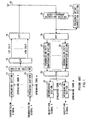
- Hereinafter, a conventional OFDM-CDMA-based communication apparatus will be explained using FIG.1. FIG.1 is a block diagram showing a configuration of a conventional OFDM-CDMA-based communication apparatus.
- In the transmission system shown in FIG.1, each spreading
section 11 carries out spreading processing by multiplyingtransmission signals 1 to n by theirrespective spreading codes 1 to n. Here, suppose their spreading factor is k. -
Addition section 12 adds up the transmission signals subjected to spreading processing. Serial/parallel (hereinafter referred to as "S/P")converter 13 converts a serial signal to a plurality of parallel signals. This S/P converter 13 divides the transmission signals thus spread and added up by spread signal or breaks downspread transmission signals 1 to n by spread signal (chip), that is, A 1st to kth chip. - IFFT
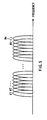
processing section 14 carries out inverse Fourier transform processing on a plurality of parallel signals. ThisIFFT processing section 14 assigns one subcarrier to one chip data signal string and carries out frequency division multiplexing. - That is, the number of subcarriers corresponds to the spreading factor and it is "k" in this case. Suppose the 1st chip of
transmission signals 1 to n is placed insubcarrier 1 and the kth chip oftransmission signals 1 to n is placed in subcarrier k. That is, a chip data string is subjected to frequency division multiplexing. FIG.2 shows this mode.Antenna 15 transmits/receives a radio signal. - In the reception system, quasi-coherent
detection section 16 carries out quasi coherent detection processing on the reception signal fromantenna 15. That is, quasi-coherentdetection section 16 carries out quasi-coherent detection processing under the control of a local signal subjected to frequency offset correction from frequencyoffset correction section 17, which will be described later. In this way, frequency offset correction is performed. - Frequency
offset correction section 17 detects a frequency offset using the signal after quasi-coherent detection processing and creates a local signal based on this frequency offset. That is, frequencyoffset correction section 17 outputs the local signal subjected to frequency offset correction to quasi-coherentdetection section 16. -
FFT processing section 18 carries out Fourier transform processing on the reception signal subjected to quasi-coherent detection processing and extracts each subcarrier signal (chip data signal string). Transmissionpath compensation sections 19 are provided in one-to-one correspondence with subcarriers and carry out compensation processing such as phase compensation on their respective subcarrier reception signals. - Parallel/serial (hereinafter referred to as "P/S")
converter 20 converts a plurality of parallel signals into a single serial signal. This P/S converter 20 rearranges the subcarrier signals from one chip to another and outputs the 1st chip of a signal on which spreadtransmission signals 1 to n are multiplexed at time t1, the 2nd chip of a signal on which spreadtransmission signals 1 to n are multiplexed at time t2, ... up to the kth chip of a signal on which spreadtransmission signals 1 to n are multiplexed at time tk. - Despreading
sections 21 carry out despreading processing by multiplying the reception signal which has been converted to a single serial signal by theirrespective spreading codes 1 to n and extracting only the signals spread using those codes. - However, the above OFDM-CDMA-based communication apparatus has problems as shown below. That is, if the frequency offset detected by frequency
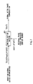
offset correction section 17 above contains a detection error, the reception signal after FFT processing contains a residual phase error. - This results in the reception signal after FFT processing involving phase rotation. For example, as shown in FIG.3, 1f the frequency offset contains a detection error of Δf, the 1st chip to kth chip corresponding to
2nd transmission signals 1 to n contain a residual phase error with 2π ΔfT. The 1st chip to kth chip corresponding to3rd transmission signals 1 to n contain a residual phase error with 2πΔf2T. Here, T is signal transmission speed before spreading processing. - Thus, the reception signals obtained from those signals containing residual phase errors have a deteriorated error rate characteristic.
- Document "A New Multi-carrier CDMA/TDD Transmission Scheme Based on Cyclic Extended Spread Code for 4th Generation Mobile Communication System" a Personal Wireless Communications, 1997 IEEE International Conference in Bumbai, India, 17-20 December; 1997, New York, USA, IEEE, US 17 December 1997, pages 319 through 323, discloses that the fixed pattern pilot data is inserted and spread by one of the cyclic extended PN sequences to estimate multi-path characteristics of mobile radio channel and multiplexed with the signals of other traffic channels. This spread data of all traffic and pilot channel are modulated and multiplexed with OFDM and transmitted to the air. At the receiver, the received data are fed into the DFT circuit and detected as subchannel data. The subchannel data are fed into a multicode division multiplex receiver unit.
- Document "Downlink Detection Schemes for MC-CDM A in Indoor Environments", IEICE TRANS. COMMUN., VOL E79-B, NO. 9, September 1996, pages 1351-1360 discloses a reception apparatus/method according to the preamble of the independent claims.
- It is an object of the present invention to provide an OFDM-CDMA-based communication apparatus capable of compensating residual phase errors.
- This object is achieved by adopting an apparatus and a method as defined in the present claims.
- The above and other objects and features of the invention will appear more fully hereinafter from a consideration of the following description taken in connection with the accompanying drawing wherein one example is illustrated by way of example, in which;
- FIG.1 is a block diagram showing a configuration of a conventional OFDM-CDMA-based communication apparatus;
- FIG.2 is a schematic diagram showing an example of subcarrier placement of the conventional OFDM-CDMA-based communication apparatus;
- FIG.3 is a schematic diagram showing an amount of phase rotation contained in a reception signal of the conventional OFDM-CDMA-based communication apparatus;
- FIG.4 is a block diagram showing a configuration of an OFDM-CDMA-based communication apparatus according to
Embodiment 1 of the present invention; - FIG.5 is a schematic diagram showing an example of subcarrier placement of the OFDM-CDMA-based communication apparatus according to
Embodiment 1 above; - FIG.6 is a block diagram showing a configuration of a residual phase error detection section of the OFDM-CDMA-based communication apparatus according to
Embodiment 1 above; - FIG.7 is a block diagram showing a configuration of a phase compensation section of the OFDM-CDMA-based communication apparatus according to
Embodiment 1 above; and - FIG.8 is a block diagram showing a configuration of an OFDM-CDMA-based communication apparatus according to
Embodiment 2 of the present invention. - With reference now to the attached drawings, embodiments of the present invention will be explained in detail below.
- FIG.4 is a block diagram showing a configuration of an OFDM-CDMA-based communication apparatus according to
Embodiment 1 of the present invention. In the transmission system shown in FIG.4, each spreadingsection 101 carries out spreading processing by multiplyingtransmission signals 1 to n by theirrespective spreading codes 1 to n. Spreadingsection 102 carries out spreading processing by multiplying a known signal by a spreading code for the known signal. Here, suppose their spreading factor is k. -
Addition section 103 multiplexes the transmission signals subjected to spreading processing by each spreading section and the known signal. S/P converter 104 divides the multiplexed and spread transmission signals and known signal by spread signal and breaks downspread transmission signals 1 to n and known signal by spread signal. That is, S/P converter 104 breaks downspread transmission signals 1 to n and known signal into a 1st chip to kth chip. -
IFFT processing section 105 carries out inverse Fourier transform processing on a plurality of parallel signals. Here,IFFT processing section 105 assigns one subcarrier (carrier) to one chip data signal string and carries out frequency division multiplexing. That is, the number of subcarriers corresponds to the spreading factor and it is k in this case. Suppose the 1st chip oftransmission signals 1 to n is placed insubcarrier 1 and the kth chip oftransmission signals 1 to n is placed in subcarrier k. In other words,IFFT processing section 105 subjects a chip data string to frequency division multiplexing. FIG.5 shows this mode.Antenna 106 transmits/receives a radio signal. - In the reception system,
FFT processing section 107 carries out Fourier transform processing on the reception signal fromantenna 106 and extracts each subcarrier signal (chip data signal string). Here, the reception signal sent toFFT processing section 107 can also be the one subjected to frequency offset correction according to the above conventional system. - Each transmission
path compensation section 108 is provided in one-to-one correspondence with subcarriers. Each transmissionpath compensation section 108 carries out compensation processing such as phase compensation on their respective subcarrier reception signals. - P/
S converter 109 converts a plurality of parallel signals into a single serial signal. This P/S converter 109 rearranges subcarrier signals from one chip to another and outputs the first chip of a signal on which spreadtransmission signals 1 to n and the known signal are multiplexed at time t1, the second chip of a signal on which spreadtransmission signals 1 to n and the known signal are multiplexed at time t2, ... up to the kth chip of a signal on which spreadtransmission signals 1 to n and the known signal are multiplexed at time tk. - Each
despreading section 110 carries out despreading processing by multiplying the reception signal which has been converted to a single serial signal by their respective spreadingcodes 1 to n and extracting only the signals spread by those codes.Despreading section 111 carries out despreading processing by multiplying the reception signal which has been converted to a single serial signal by a known signal spreading code and extracting only the known signal spread by this code. - Residual phase
error detection section 113 detects a residual phase error using the known signal, that is, the same known signal used in the transmission system and the despread signal (received known signal) from thedespreading section 111. Here, the method of detecting a residual phase error by residual phaseerror detection section 113 will be explained using FIG.6. FIG.6 is a block diagram showing a configuration of the residual phase error detection section of the OFDM-CDMA-based communication apparatus according toEmbodiment 1 of the present invention. - Here, suppose residual phase error θ(nT) exists in the despread signal. In this case, despread signal RX(nT) is expressed in the following expression:

where TX(nT) is transmission signal n (n=1, 2, 3, ...). - Furthermore, if residual phase error θ(nT) exists, despread known signal RXPi(nT), that is, the signal from
despreading section 111 is expressed in the following expression.
where A(nT) is reception amplitude information of the known signal and Pi(nT) is the known signal. - In FIG.6,
multiplication section 301 multiplies despread known signal RXPi(nT) shown inexpression ② by known signal Pi(nT). In this way, the signal output bymultiplication section 301 is expressed in the following expression. Here, suppose |RXPi(nT)| = 1.
- Then,
division section 302 normalizes the signal frommultiplication section 301, that is, the signal shown in expression ③ using the reception amplitude information A(nT) fromenvelope generation section 303. In this way, from division section 302 a residual phase error expressed in the following expression is detected.
- Furthermore,
conjugate generation section 304 generates a conjugate complex number of the signal fromdivision section 302, that is, the signal shown in expression ④. In this way, conjugate complex number of the residual phase error exp(-jθ(nT)) is created. This is how the residual phaseerror detection section 113 detects a residual phase error. - In FIG.4, residual phase
error detection section 113 outputs the conjugate complex number of the detected residual phase error to each ofphase compensation sections 112. Eachphase compensation section 112 compensates the residual phase error for the despread reception signals from despreadingsections 110 using the above conjugate complex numbers of the above residual phase errors. Here, the method of compensating a residual phase error byphase compensation sections 112 will be explained using FIG.7. FIG. 7 is a block diagram showing a configuration of a phase compensation section of the OFDM-CDMA-based communication apparatus according toEmbodiment 1 of the present invention. - As shown in FIG.7,
multiplication section 401 multiplies reception signal RX(nT) subjected to despreading processing by the conjugate complex number of residual phase error exp(-jθ(nT)). This allowsmultiplication section 401 to produce a reception signal with its residual phase error compensated as shown in the following expression:
- That is,
phase compensation sections 112 output signals quasi-equivalent to the transmission signals in the transmission system as reception signals with a residual phase error compensated. This is howcompensation sections 112 compensate a residual phase error. - As shown above, according to this embodiment, the transmission system carries out spreading processing on a known signal provided apart from each transmission signal using a spreading code assigned to this known signal and inserts the despread known signal and each despread transmission signal into each subcarrier, while the reception system detects a residual phase error using the above known signal and received known signal obtained through the despreading processing using the above spreading code and carries out compensation processing using the detected residual phase error on the reception signal obtained through despreading processing using each spreading code, thus allowing a reception signal with an optimal errorrate characteristic to be extracted. Thus, this embodiment can provide an OFDM-CDMA-based communication apparatus capable of compensating a residual phase error.
- This embodiment describes the case where the transmission system uses one known reference signal, but the present invention is not limited to this and is also applicable to cases where the transmission system uses two or more known reference signals. In such cases, the reception system averages detected residual phase errors using each known reference signal, thus further improving the accuracy in detecting residual phase errors.
-
Embodiment 2 is an improved version ofEmbodiment 1 with the transmission system having a known signal whose signal level is higher than the levels of other transmission signals and the reception system with an improved signal-to-noise ratio when receiving the above known signal, thus improving the accuracy in detecting phase errors and preventing deterioration of the error rate characteristic of each reception signal. The OFDM-CDMA-based communication apparatus according to this embodiment will be explained using FIG.8. - FIG.8 is a block diagram showing a configuration of the OFDM-CDMA-based communication apparatus according to
Embodiment 2 of the present invention. The parts with the same configuration as that in Embodiment 1 (FIG.4) are assigned the same reference numerals and their explanations are omitted. - In FIG.8,
multiplication section 501 receives gain-related information and a known signal as inputs and outputs a signal obtained by multiplying this known signal by a factor indicating the above gain to spreadingsection 102. This allows the reception system to have an improved signal-to-noise ratio when receiving the above known signal, which improves the accuracy in detecting phase errors in residual phaseerror detection section 113. This makes it possible to further suppress deterioration of the error rate characteristic of each reception signal compared toEmbodiment 1. - Thus, this embodiment can prevent the error rate characteristic of each reception signal from deteriorating in the reception system by having a known signal whose signal level is higher than the levels of other transmission signals in the transmission system.
- When two or more known reference signals are used, it goes without saying that the transmission system raises the signal level of each known reference signal as shown above. This allows the accuracy in detecting residual phase errors to be further improved, making it possible to prevent the error rate characteristic of each reception signal from deteriorating in the reception system.
- Multiplexing a spread known signal with data is also applicable to a direct spreading CDMA system, but when the reception signal level falls or when interference between codes is large, deterioration of the residual phase error detection characteristic is also large.
- On the other hand, when multiplexing a spread known signal with data is applied to an OFDM-CDMA system, it is possible to obtain a high accuracy residual phase error detection characteristic even when the reception signal level falls or when interference between codes is large for the following reasons:
- ① Even if the reception level of a certain subcarrier falls, there are still other subcarriers whose reception level has not fallen, which allows a frequency diversity effect to be obtained.
- ② A guard interval prevents influences of interference between codes.
- As described above, according to the present invention, the transmission system carries out spreading processing on a known signal provided apart from each transmission signal using a spreading code assigned to this known signal and inserts each transmission signal subjected to spreading processing and the known signal subjected to spreading processing into each subcarrier, and the reception system detects a residual phase error using the received known signal obtained through despreading processing using the above spreading code and the above known signal and carries out compensation processing on each reception signal using the detected residual phase error, thus providing an OFDM-CDMA-based communication apparatus capable of compensating residual phase errors.
- The present invention is not limited to the above described embodiments, and various variations and modifications may be possible without departing from the scope of the present invention.
Claims (4)
- An OFDM-CDMA reception apparatus comprising;a frequency division demultiplexer (107) for demultiplexing a received signal into a plurality of subcarriers which are each assigned a separate chip comprising information about a plurality of differently spread transmission signals and at least one known signal;a parallel to serial converter (109) for converting the parallel output of the frequency division multiplexer into a serial stream;a first demodulator (110) for carrying out despreading processing on the serial stream using a corresponding one of a plurality of predetermined spreading codes, to thereby extract received versions of the transmission signals;characterized bya second demodulator (111) for carrying out despreading processing on the serial stream using a corresponding one of a plurality of said spreading codes, to thereby extract a received version of the known signal;a phase error detector (113) for detecting a residual phase error using the known signal and the received version of the known signal; anda phase compensator (112) for carrying out phase compensation on each of said received version of transmission signals using the residual phase error.
- A communication terminal apparatus equipped with an OFDM-CDMA reception apparatus as defined in claim 1.
- A base station apparatus equipped with an OFDM-CDMA reception apparatus as defined in claim 1.
- A reception method comprising:a frequency division demultiplexing step for demultiplexing a received signal into a plurality of subcarriers which are each assigned a separate chip comprising information about a plurality of differently spread transmission signals and at least one known signal;a parallel to serial converting step for converting the parallel output of the frequency division multiplexer into a serial stream;a first demodulating step for carrying out despreading processing on the serial stream using a corresponding one of a plurality of predetermined spreading codes, to thereby extract received versions of the transmission signals;characterized bya second demodulating step for carrying out despreading processing on the serial stream using a corresponding one of a plurality of said spreading codes, to thereby extract a received version of the known signal;a phase error detecting step for detecting a residual phase error using the known signal and the received version of the known signal; anda phase compensating step for carrying out phase compensation on each of said received version of transmission signals using the residual phase error.
Priority Applications (1)
| Application Number | Priority Date | Filing Date | Title |
|---|---|---|---|
| EP20050027646 EP1638242A3 (en) | 1999-07-13 | 2000-07-11 | OFDM-CDMA transmission apparatus and corresponding method |
Applications Claiming Priority (2)
| Application Number | Priority Date | Filing Date | Title |
|---|---|---|---|
| JP19894399 | 1999-07-13 | ||
| JP19894399A JP3715141B2 (en) | 1999-07-13 | 1999-07-13 | Communication terminal device |
Related Child Applications (1)
| Application Number | Title | Priority Date | Filing Date |
|---|---|---|---|
| EP20050027646 Division EP1638242A3 (en) | 1999-07-13 | 2000-07-11 | OFDM-CDMA transmission apparatus and corresponding method |
Publications (3)
| Publication Number | Publication Date |
|---|---|
| EP1069725A2 EP1069725A2 (en) | 2001-01-17 |
| EP1069725A3 EP1069725A3 (en) | 2004-01-07 |
| EP1069725B1 true EP1069725B1 (en) | 2006-02-22 |
Family
ID=16399553
Family Applications (2)
| Application Number | Title | Priority Date | Filing Date |
|---|---|---|---|
| EP20000114855 Expired - Lifetime EP1069725B1 (en) | 1999-07-13 | 2000-07-11 | Spread spectrum, multicarrier transmission |
| EP20050027646 Ceased EP1638242A3 (en) | 1999-07-13 | 2000-07-11 | OFDM-CDMA transmission apparatus and corresponding method |
Family Applications After (1)
| Application Number | Title | Priority Date | Filing Date |
|---|---|---|---|
| EP20050027646 Ceased EP1638242A3 (en) | 1999-07-13 | 2000-07-11 | OFDM-CDMA transmission apparatus and corresponding method |
Country Status (6)
| Country | Link |
|---|---|
| US (1) | US7161895B1 (en) |
| EP (2) | EP1069725B1 (en) |
| JP (1) | JP3715141B2 (en) |
| KR (1) | KR100381514B1 (en) |
| CN (1) | CN1159872C (en) |
| DE (1) | DE60026094T2 (en) |
Families Citing this family (37)
| Publication number | Priority date | Publication date | Assignee | Title |
|---|---|---|---|---|
| JP4000057B2 (en) * | 2000-11-17 | 2007-10-31 | 松下電器産業株式会社 | OFDM communication device |
| KR100392642B1 (en) * | 2000-11-20 | 2003-07-23 | 에스케이 텔레콤주식회사 | A mobile terminal capable of multi-carrier transmission and receipt |
| GB2370476A (en) * | 2000-12-22 | 2002-06-26 | Ubinetics | Combined demodulation of OFDM and CDMA signals using reduced area on an ASIC by sharing FFT hardware |
| KR100375350B1 (en) * | 2001-03-26 | 2003-03-08 | 삼성전자주식회사 | Data communication apparatus and method based on the Orthogonal Frequency Division Multiple Access |
| JP3628977B2 (en) * | 2001-05-16 | 2005-03-16 | 松下電器産業株式会社 | Radio base station apparatus and communication terminal apparatus |
| JP3676991B2 (en) * | 2001-07-05 | 2005-07-27 | 松下電器産業株式会社 | Wireless communication apparatus and wireless communication method |
| WO2003026297A1 (en) * | 2001-09-12 | 2003-03-27 | Samsung Electronics Co., Ltd. | Method and apparatus for transferring channel information in ofdm communications |
| CN1557064B (en) * | 2001-09-18 | 2013-02-06 | 西门子公司 | Method and communication system device for the generation or processing of OFDM symbols in a transmission system with spread user data |
| US20030081538A1 (en) * | 2001-10-18 | 2003-05-01 | Walton Jay R. | Multiple-access hybrid OFDM-CDMA system |
| JP3941466B2 (en) * | 2001-11-14 | 2007-07-04 | 三菱電機株式会社 | Multi-carrier code division multiplexing communication apparatus, multi-carrier code division multiplexing communication method, multi-carrier code division multiplexing transmission apparatus, and multi-carrier code division multiplexing transmission method |
| JP3727283B2 (en) | 2001-11-26 | 2005-12-14 | 松下電器産業株式会社 | Wireless transmission device, wireless reception device, and wireless transmission method |
| BR0214622A (en) * | 2001-11-29 | 2004-11-23 | Interdigital Tech Corp | Efficient multi-in and multi-out system for multipath fading channels |
| JP2003319005A (en) * | 2002-02-20 | 2003-11-07 | Mitsubishi Electric Corp | Symbol timing correction circuit, receiver, symbol timing correction method, and demodulation process method |
| JP3564108B2 (en) * | 2002-03-08 | 2004-09-08 | イビデン産業株式会社 | Wire spread spectrum communication apparatus, communication method thereof, and wire spread spectrum communication system |
| KR100532586B1 (en) * | 2002-10-30 | 2005-12-02 | 한국전자통신연구원 | Appratus and Method for transmitting and receiving using orthogonal code and non binary value in CDMA/OFDM |
| JP4256158B2 (en) * | 2002-12-26 | 2009-04-22 | パナソニック株式会社 | Wireless communication apparatus and wireless communication method |
| WO2004095749A1 (en) | 2003-04-24 | 2004-11-04 | Nec Corporation | Radio transmitting/receiving apparatus and radio transmitting/receiving method for estimating noise and interference power in ratio transmission using code spread |
| CN1317863C (en) * | 2003-07-02 | 2007-05-23 | 矽统科技股份有限公司 | Frequency displacement compensation estimating system for WLAN and method thereof |
| US7315563B2 (en) * | 2003-12-03 | 2008-01-01 | Ut-Battelle Llc | Multicarrier orthogonal spread-spectrum (MOSS) data communications |
| US7336600B2 (en) * | 2003-12-29 | 2008-02-26 | Industrial Technology Research Institute | Cell search method for orthogonal frequency division multiplexing based cellular communication system |
| US7397839B2 (en) | 2004-01-27 | 2008-07-08 | Ntt Docomo, Inc. | OFDM communication system and method |
| EP1596521B1 (en) * | 2004-05-13 | 2013-04-03 | NTT DoCoMo, Inc. | Signal separation device and signal separation method |
| EP1655918A3 (en) | 2004-11-03 | 2012-11-21 | Broadcom Corporation | A low-rate long-range mode for OFDM wireless LAN |
| WO2006064549A1 (en) * | 2004-12-14 | 2006-06-22 | Fujitsu Limited | Spreading code allocating method, despreading method, transmitter, receiver, communication device, wireless base station device, and mobile terminal |
| US8442441B2 (en) * | 2004-12-23 | 2013-05-14 | Qualcomm Incorporated | Traffic interference cancellation |
| KR20080022104A (en) * | 2005-07-07 | 2008-03-10 | 노키아 코포레이션 | Techniques to improve redundancy for multi-carrier wireless systems |
| KR101154979B1 (en) * | 2005-07-22 | 2012-06-18 | 엘지전자 주식회사 | apparatus for receiving and transmitting data of multi-carrier system and method for receiving and transmitting data using the same |
| JP4504317B2 (en) * | 2006-01-17 | 2010-07-14 | 学校法人同志社 | MC-CDMA system, transmitter and receiver |
| JP4732947B2 (en) * | 2006-05-01 | 2011-07-27 | 日本電信電話株式会社 | OFDM communication system, OFDM communication method, OFDM signal transmitting apparatus, and OFDM signal receiving apparatus |
| CN101119351A (en) * | 2006-08-02 | 2008-02-06 | 华为技术有限公司 | OFDM signal receiving and dispatching method and apparatus |
| KR100934502B1 (en) * | 2007-02-06 | 2009-12-30 | 삼성전자주식회사 | Signal transceiving device and method in communication system |
| CN105610751B (en) * | 2007-12-19 | 2019-07-23 | 福尔肯纳米有限公司 | For improving communication speed, spectrum efficiency and realizing that the common waveform of other benefits and sideband inhibit communication system and method |
| KR101513044B1 (en) * | 2008-08-05 | 2015-04-17 | 엘지전자 주식회사 | Radio access method for reduced papr |
| JP5365132B2 (en) * | 2008-10-17 | 2013-12-11 | 富士ゼロックス株式会社 | Serial signal receiver, serial transmission system, serial transmission method, serial signal transmitter |
| CN101753501A (en) * | 2008-11-28 | 2010-06-23 | Tcl集团股份有限公司 | Method for combining TD-SCDMA downlink with orthogonal frequency division multiplexing |
| US8982924B2 (en) * | 2010-03-02 | 2015-03-17 | The Aerospace Corporation | Architectures and methods for code combiners |
| US9979583B2 (en) * | 2015-09-25 | 2018-05-22 | Nxp Usa, Inc. | Methods and system for generating a waveform for transmitting data to a plurality of receivers and for decoding the received waveform |
Family Cites Families (34)
| Publication number | Priority date | Publication date | Assignee | Title |
|---|---|---|---|---|
| US3735266A (en) * | 1971-12-20 | 1973-05-22 | Bell Telephone Labor Inc | Method and apparatus for reducing crosstalk on cross-polarized communication links |
| GB9020170D0 (en) * | 1990-09-14 | 1990-10-24 | Indep Broadcasting Authority | Orthogonal frequency division multiplexing |
| US5559789A (en) * | 1994-01-31 | 1996-09-24 | Matsushita Electric Industrial Co., Ltd. | CDMA/TDD Radio Communication System |
| JPH07226710A (en) | 1994-02-16 | 1995-08-22 | Matsushita Electric Ind Co Ltd | Cdma/tdd system radio communication system |
| US5710768A (en) * | 1994-09-30 | 1998-01-20 | Qualcomm Incorporated | Method of searching for a bursty signal |
| US5822359A (en) * | 1994-10-17 | 1998-10-13 | Motorola, Inc. | Coherent random access channel in a spread-spectrum communication system and method |
| JP3130752B2 (en) * | 1995-02-24 | 2001-01-31 | 株式会社東芝 | OFDM transmission receiving method and transmitting / receiving apparatus |
| JPH08331095A (en) | 1995-05-31 | 1996-12-13 | Sony Corp | Communication system |
| JP2863993B2 (en) * | 1995-06-22 | 1999-03-03 | 松下電器産業株式会社 | CDMA wireless multiplex transmitting apparatus, CDMA wireless multiplex transmitting apparatus, CDMA wireless receiving apparatus, and CDMA wireless multiplex transmitting method |
| US6831905B1 (en) * | 1995-06-30 | 2004-12-14 | Interdigital Technology Corporation | Spread spectrum system assigning information signals to message-code signals |
| ZA965340B (en) * | 1995-06-30 | 1997-01-27 | Interdigital Tech Corp | Code division multiple access (cdma) communication system |
| JP3200547B2 (en) | 1995-09-11 | 2001-08-20 | 株式会社日立製作所 | CDMA mobile communication system |
| US5815488A (en) * | 1995-09-28 | 1998-09-29 | Cable Television Laboratories, Inc. | Multiple user access method using OFDM |
| JP2820919B2 (en) * | 1996-03-25 | 1998-11-05 | 株式会社ワイ・アール・ピー移動通信基盤技術研究所 | CDMA mobile communication system and transceiver |
| JPH1051354A (en) * | 1996-05-30 | 1998-02-20 | N T T Ido Tsushinmo Kk | Ds-cdma transmission method |
| US6067292A (en) * | 1996-08-20 | 2000-05-23 | Lucent Technologies Inc | Pilot interference cancellation for a coherent wireless code division multiple access receiver |
| JP2798130B2 (en) * | 1996-08-29 | 1998-09-17 | 日本電気株式会社 | CDMA communication system |
| FI102577B (en) * | 1996-09-05 | 1998-12-31 | Nokia Telecommunications Oy | Transmission and reception method and radio system |
| US6359938B1 (en) * | 1996-10-31 | 2002-03-19 | Discovision Associates | Single chip VLSI implementation of a digital receiver employing orthogonal frequency division multiplexing |
| JPH10190521A (en) * | 1996-12-20 | 1998-07-21 | Fujitsu Ltd | Radio communication equipment and radio communication system |
| US6408016B1 (en) * | 1997-02-24 | 2002-06-18 | At&T Wireless Services, Inc. | Adaptive weight update method and system for a discrete multitone spread spectrum communications system |
| US5943331A (en) * | 1997-02-28 | 1999-08-24 | Interdigital Technology Corporation | Orthogonal code synchronization system and method for spread spectrum CDMA communications |
| KR100213100B1 (en) | 1997-04-10 | 1999-08-02 | 윤종용 | Frequency error corrector for orthogonal frequency division multiplexing and method therefor |
| JP3335887B2 (en) | 1997-08-20 | 2002-10-21 | 松下電器産業株式会社 | Spread spectrum demodulator and spread spectrum demodulation method |
| JPH10262028A (en) | 1998-03-25 | 1998-09-29 | Matsushita Electric Ind Co Ltd | Cdma radio multiplex transmitting device and method therefor |
| US6366607B1 (en) * | 1998-05-14 | 2002-04-02 | Interdigital Technology Corporation | Processing for improved performance and reduced pilot |
| US6442152B1 (en) * | 1998-07-13 | 2002-08-27 | Samsung Electronics, Co., Ltd. | Device and method for communicating packet data in mobile communication system |
| JP2988522B1 (en) * | 1998-09-28 | 1999-12-13 | 日本電気株式会社 | CDMA transmitter |
| US6542485B1 (en) * | 1998-11-25 | 2003-04-01 | Lucent Technologies Inc. | Methods and apparatus for wireless communication using time division duplex time-slotted CDMA |
| JP3678944B2 (en) * | 1999-07-02 | 2005-08-03 | 松下電器産業株式会社 | Wireless communication apparatus and wireless communication method |
| JP3727283B2 (en) * | 2001-11-26 | 2005-12-14 | 松下電器産業株式会社 | Wireless transmission device, wireless reception device, and wireless transmission method |
| JP4142917B2 (en) * | 2002-08-23 | 2008-09-03 | 松下電器産業株式会社 | CDMA transmitter and OFDM-CDMA transmitter |
| CN100579309C (en) * | 2002-08-23 | 2010-01-06 | 松下电器产业株式会社 | OFDM-CDMA transmission device and OFDM-CDMA transmission method |
| JP3732830B2 (en) * | 2002-10-10 | 2006-01-11 | 松下電器産業株式会社 | Multicarrier transmission apparatus and multicarrier transmission method |
-
1999
- 1999-07-13 JP JP19894399A patent/JP3715141B2/en not_active Expired - Fee Related
-
2000
- 2000-07-10 US US09/613,527 patent/US7161895B1/en not_active Expired - Fee Related
- 2000-07-11 EP EP20000114855 patent/EP1069725B1/en not_active Expired - Lifetime
- 2000-07-11 EP EP20050027646 patent/EP1638242A3/en not_active Ceased
- 2000-07-11 DE DE2000626094 patent/DE60026094T2/en not_active Expired - Lifetime
- 2000-07-12 KR KR10-2000-0039811A patent/KR100381514B1/en not_active IP Right Cessation
- 2000-07-13 CN CNB001240250A patent/CN1159872C/en not_active Expired - Fee Related
Non-Patent Citations (2)
| Title |
|---|
| FARHANG-BOROUJENY B.: "Pilot-based channel identification: Proposal for semi-blind identification of communication channels", ELECTRONICS LETTERS, vol. 31, no. 13, 22 June 1995 (1995-06-22), IEE STEVENAGE, GB * |
| TOMBA L.; KRZYMIEN W.A.: "DOWNLINK DETECTION SCHEMES FOR MC-CDMA SYSTEMS IN INDOOR ENVIRONMENTS", IEICE TRANSACTIONS ON COMMUNICATIONS, no. 9, 1 September 1996 (1996-09-01), TOKYO, JP * |
Also Published As
| Publication number | Publication date |
|---|---|
| EP1638242A3 (en) | 2006-03-29 |
| DE60026094D1 (en) | 2006-04-27 |
| JP3715141B2 (en) | 2005-11-09 |
| DE60026094T2 (en) | 2006-08-10 |
| EP1069725A3 (en) | 2004-01-07 |
| CN1280427A (en) | 2001-01-17 |
| EP1638242A2 (en) | 2006-03-22 |
| CN1159872C (en) | 2004-07-28 |
| US7161895B1 (en) | 2007-01-09 |
| KR100381514B1 (en) | 2003-04-23 |
| KR20010015294A (en) | 2001-02-26 |
| JP2001028557A (en) | 2001-01-30 |
| EP1069725A2 (en) | 2001-01-17 |
Similar Documents
| Publication | Publication Date | Title |
|---|---|---|
| EP1069725B1 (en) | Spread spectrum, multicarrier transmission | |
| US10270574B2 (en) | Transmission signal generation apparatus, transmission signal generation method, reception signal apparatus, and reception signal method | |
| US6282185B1 (en) | Transmitting and receiving method and radio system | |
| EP2076980B1 (en) | Tdm based cell search method for ofdm system | |
| US20180270725A1 (en) | System Access and Synchronization Methods for MIMO OFDM Communications Systems and Physical Layer Packet and Preamble Design | |
| US7539263B2 (en) | Method for transmitting and receiving preamble sequences in an orthogonal frequency division multiplexing communication system using a multiple input multiple output scheme | |
| EP1560359B1 (en) | OFDM communication system and method | |
| EP1337069B1 (en) | Synchronisation in a spread-spectrum multicarrier system | |
| EP2187544B1 (en) | Base station apparatus, mobile station apparatus, distributed antenna wireless communications system, pilot channel generation method, synchronization channel generation method, and antenna selection method | |
| KR100715913B1 (en) | Apparatus of up-link ranging signal detection in orthogonal frequency division multiple access cellular system and the method thereof | |
| US20060126491A1 (en) | Cell search apparatus and method in a mobile communication system using multiple access scheme | |
| US7283559B2 (en) | Transmitting/receiving apparatus and method for packet data service in a mobile telecommunication system | |
| US20060056528A1 (en) | Method of transmitting and receiving preamble sequences in an orthogonal frequency division multiplexing communication system using multiple input multiple output scheme | |
| US20040009783A1 (en) | Multi-carrier transmission apparatus, multi-carrier reception apparatus, and multi-carrier radio communication method | |
| US20030210735A1 (en) | System and method for demodulating multiple walsh codes using a chip combiner | |
| KR20050041804A (en) | Apparatus and method for transmitting/receiving pilot in an orthogonal frequency division multiplexing communication system | |
| JP2001024618A (en) | Transmitter-receiver | |
| US20060233125A1 (en) | Radio access scheme in CDMA-based communication system | |
| JP3581281B2 (en) | OFDM-CDMA receiving apparatus and OFDM-CDMA transmitting apparatus | |
| JPH10190626A (en) | Cdma reception device | |
| US20030137957A1 (en) | Radio transmitting and receiving device and radio communication system | |
| JP3679014B2 (en) | Wireless communication device | |
| EP1999859B1 (en) | Apparatus and method for efficiently transmitting/receiving a control channel in a mobile communication system simultaneously supporting a synchronous hrpd system and an ofdm system | |
| KR20050018296A (en) | Apparatus and method for transmitting/receiving pilot in an orthogonal frequency division multiplexing communication system | |
| EP1617583A1 (en) | Radio transmitting/receiving apparatus and radio transmitting/receiving method for estimating noise and interference power in ratio transmission using code spread |
Legal Events
| Date | Code | Title | Description |
|---|---|---|---|
| PUAI | Public reference made under article 153(3) epc to a published international application that has entered the european phase |
Free format text: ORIGINAL CODE: 0009012 |
|
| AK | Designated contracting states |
Kind code of ref document: A2 Designated state(s): AT BE CH CY DE DK ES FI FR GB GR IE IT LI LU MC NL PT SE |
|
| AX | Request for extension of the european patent |
Free format text: AL;LT;LV;MK;RO;SI |
|
| PUAL | Search report despatched |
Free format text: ORIGINAL CODE: 0009013 |
|
| RIC1 | Information provided on ipc code assigned before grant |
Ipc: 7H 04L 27/26 B Ipc: 7H 04L 5/02 A |
|
| AK | Designated contracting states |
Kind code of ref document: A3 Designated state(s): AT BE CH CY DE DK ES FI FR GB GR IE IT LI LU MC NL PT SE |
|
| AX | Request for extension of the european patent |
Extension state: AL LT LV MK RO SI |
|
| 17P | Request for examination filed |
Effective date: 20040303 |
|
| 17Q | First examination report despatched |
Effective date: 20040330 |
|
| AKX | Designation fees paid |
Designated state(s): DE FR GB SE |
|
| GRAP | Despatch of communication of intention to grant a patent |
Free format text: ORIGINAL CODE: EPIDOSNIGR1 |
|
| GRAS | Grant fee paid |
Free format text: ORIGINAL CODE: EPIDOSNIGR3 |
|
| GRAA | (expected) grant |
Free format text: ORIGINAL CODE: 0009210 |
|
| AK | Designated contracting states |
Kind code of ref document: B1 Designated state(s): DE FR GB SE |
|
| REG | Reference to a national code |
Ref country code: GB Ref legal event code: FG4D |
|
| REF | Corresponds to: |
Ref document number: 60026094 Country of ref document: DE Date of ref document: 20060427 Kind code of ref document: P |
|
| PG25 | Lapsed in a contracting state [announced via postgrant information from national office to epo] |
Ref country code: SE Free format text: LAPSE BECAUSE OF FAILURE TO SUBMIT A TRANSLATION OF THE DESCRIPTION OR TO PAY THE FEE WITHIN THE PRESCRIBED TIME-LIMIT Effective date: 20060522 |
|
| ET | Fr: translation filed | ||
| PLBE | No opposition filed within time limit |
Free format text: ORIGINAL CODE: 0009261 |
|
| STAA | Information on the status of an ep patent application or granted ep patent |
Free format text: STATUS: NO OPPOSITION FILED WITHIN TIME LIMIT |
|
| 26N | No opposition filed |
Effective date: 20061123 |
|
| REG | Reference to a national code |
Ref country code: DE Ref legal event code: R082 Ref document number: 60026094 Country of ref document: DE Representative=s name: GRUENECKER, KINKELDEY, STOCKMAIR & SCHWANHAEUS, DE |
|
| REG | Reference to a national code |
Ref country code: FR Ref legal event code: CD Owner name: PANASONIC CORPORATION, JP Effective date: 20140612 |
|
| REG | Reference to a national code |
Ref country code: GB Ref legal event code: 732E Free format text: REGISTERED BETWEEN 20140626 AND 20140702 |
|
| REG | Reference to a national code |
Ref country code: DE Ref legal event code: R082 Ref document number: 60026094 Country of ref document: DE Representative=s name: GRUENECKER, KINKELDEY, STOCKMAIR & SCHWANHAEUS, DE Effective date: 20140630 Ref country code: DE Ref legal event code: R081 Ref document number: 60026094 Country of ref document: DE Owner name: PANASONIC INTELLECTUAL PROPERTY CORPORATION OF, US Free format text: FORMER OWNER: PANASONIC CORPORATION, KADOMA-SHI, OSAKA, JP Effective date: 20140630 Ref country code: DE Ref legal event code: R082 Ref document number: 60026094 Country of ref document: DE Representative=s name: GRUENECKER PATENT- UND RECHTSANWAELTE PARTG MB, DE Effective date: 20140630 |
|
| REG | Reference to a national code |
Ref country code: FR Ref legal event code: TP Owner name: PANASONIC INTELLECTUAL PROPERTY CORPORATION OF, US Effective date: 20141014 |
|
| REG | Reference to a national code |
Ref country code: FR Ref legal event code: PLFP Year of fee payment: 16 |
|
| PGFP | Annual fee paid to national office [announced via postgrant information from national office to epo] |
Ref country code: DE Payment date: 20150707 Year of fee payment: 16 Ref country code: GB Payment date: 20150708 Year of fee payment: 16 |
|
| PGFP | Annual fee paid to national office [announced via postgrant information from national office to epo] |
Ref country code: FR Payment date: 20150629 Year of fee payment: 16 |
|
| REG | Reference to a national code |
Ref country code: DE Ref legal event code: R119 Ref document number: 60026094 Country of ref document: DE |
|
| GBPC | Gb: european patent ceased through non-payment of renewal fee |
Effective date: 20160711 |
|
| PG25 | Lapsed in a contracting state [announced via postgrant information from national office to epo] |
Ref country code: DE Free format text: LAPSE BECAUSE OF NON-PAYMENT OF DUE FEES Effective date: 20170201 Ref country code: FR Free format text: LAPSE BECAUSE OF NON-PAYMENT OF DUE FEES Effective date: 20160801 |
|
| REG | Reference to a national code |
Ref country code: FR Ref legal event code: ST Effective date: 20170331 |
|
| PG25 | Lapsed in a contracting state [announced via postgrant information from national office to epo] |
Ref country code: GB Free format text: LAPSE BECAUSE OF NON-PAYMENT OF DUE FEES Effective date: 20160711 |