EP1617536B1 - Cable connector with fluid injection port - Google Patents
Cable connector with fluid injection port Download PDFInfo
- Publication number
- EP1617536B1 EP1617536B1 EP05020059A EP05020059A EP1617536B1 EP 1617536 B1 EP1617536 B1 EP 1617536B1 EP 05020059 A EP05020059 A EP 05020059A EP 05020059 A EP05020059 A EP 05020059A EP 1617536 B1 EP1617536 B1 EP 1617536B1
- Authority
- EP
- European Patent Office
- Prior art keywords
- cable
- cable connector
- elongate conduit
- connector
- hollow interior
- Prior art date
- Legal status (The legal status is an assumption and is not a legal conclusion. Google has not performed a legal analysis and makes no representation as to the accuracy of the status listed.)
- Expired - Lifetime
Links
- 238000002347 injection Methods 0.000 title description 15
- 239000007924 injection Substances 0.000 title description 15
- 239000012530 fluid Substances 0.000 title description 12
- 239000000126 substance Substances 0.000 claims abstract description 34
- XLYOFNOQVPJJNP-UHFFFAOYSA-N water Substances O XLYOFNOQVPJJNP-UHFFFAOYSA-N 0.000 claims abstract description 12
- 230000008439 repair process Effects 0.000 claims description 27
- 238000000034 method Methods 0.000 abstract description 8
- 238000005304 joining Methods 0.000 abstract description 2
- 238000009413 insulation Methods 0.000 description 25
- 240000005572 Syzygium cordatum Species 0.000 description 14
- 235000006650 Syzygium cordatum Nutrition 0.000 description 14
- 150000001875 compounds Chemical class 0.000 description 8
- 238000013459 approach Methods 0.000 description 7
- 238000002788 crimping Methods 0.000 description 5
- IJGRMHOSHXDMSA-UHFFFAOYSA-N Atomic nitrogen Chemical compound N#N IJGRMHOSHXDMSA-UHFFFAOYSA-N 0.000 description 4
- 239000004705 High-molecular-weight polyethylene Substances 0.000 description 4
- 238000012856 packing Methods 0.000 description 4
- 229920000642 polymer Polymers 0.000 description 4
- 229920001296 polysiloxane Polymers 0.000 description 4
- 229920000181 Ethylene propylene rubber Polymers 0.000 description 3
- 239000004698 Polyethylene Substances 0.000 description 3
- 238000007906 compression Methods 0.000 description 3
- 230000006835 compression Effects 0.000 description 3
- 229920003020 cross-linked polyethylene Polymers 0.000 description 3
- 239000004703 cross-linked polyethylene Substances 0.000 description 3
- 229920001971 elastomer Polymers 0.000 description 3
- 150000002500 ions Chemical class 0.000 description 3
- 238000004519 manufacturing process Methods 0.000 description 3
- 239000000463 material Substances 0.000 description 3
- 230000035515 penetration Effects 0.000 description 3
- -1 polyethylene Polymers 0.000 description 3
- 229920000573 polyethylene Polymers 0.000 description 3
- 239000005060 rubber Substances 0.000 description 3
- 125000000391 vinyl group Chemical group [H]C([*])=C([H])[H] 0.000 description 3
- 229920002554 vinyl polymer Polymers 0.000 description 3
- 239000000356 contaminant Substances 0.000 description 2
- 238000011109 contamination Methods 0.000 description 2
- 239000007788 liquid Substances 0.000 description 2
- 229910052757 nitrogen Inorganic materials 0.000 description 2
- 239000004971 Cross linker Substances 0.000 description 1
- 239000004677 Nylon Substances 0.000 description 1
- 229910000831 Steel Inorganic materials 0.000 description 1
- 239000000853 adhesive Substances 0.000 description 1
- 230000001070 adhesive effect Effects 0.000 description 1
- 238000007605 air drying Methods 0.000 description 1
- 239000003054 catalyst Substances 0.000 description 1
- 230000008859 change Effects 0.000 description 1
- 238000004891 communication Methods 0.000 description 1
- 239000004020 conductor Substances 0.000 description 1
- 238000010276 construction Methods 0.000 description 1
- 230000007547 defect Effects 0.000 description 1
- 239000002274 desiccant Substances 0.000 description 1
- 238000009826 distribution Methods 0.000 description 1
- 238000005516 engineering process Methods 0.000 description 1
- 238000009472 formulation Methods 0.000 description 1
- 239000012212 insulator Substances 0.000 description 1
- 238000012423 maintenance Methods 0.000 description 1
- 230000005012 migration Effects 0.000 description 1
- 238000013508 migration Methods 0.000 description 1
- 239000000203 mixture Substances 0.000 description 1
- 229920001778 nylon Polymers 0.000 description 1
- 238000005192 partition Methods 0.000 description 1
- 229920003023 plastic Polymers 0.000 description 1
- 239000004033 plastic Substances 0.000 description 1
- 230000000135 prohibitive effect Effects 0.000 description 1
- 230000002787 reinforcement Effects 0.000 description 1
- 230000003014 reinforcing effect Effects 0.000 description 1
- 238000007789 sealing Methods 0.000 description 1
- 239000000243 solution Substances 0.000 description 1
- 239000010959 steel Substances 0.000 description 1
- 230000001052 transient effect Effects 0.000 description 1
Images


Classifications
-
- H—ELECTRICITY
- H02—GENERATION; CONVERSION OR DISTRIBUTION OF ELECTRIC POWER
- H02G—INSTALLATION OF ELECTRIC CABLES OR LINES, OR OF COMBINED OPTICAL AND ELECTRIC CABLES OR LINES
- H02G15/00—Cable fittings
- H02G15/08—Cable junctions
-
- H—ELECTRICITY
- H01—ELECTRIC ELEMENTS
- H01R—ELECTRICALLY-CONDUCTIVE CONNECTIONS; STRUCTURAL ASSOCIATIONS OF A PLURALITY OF MUTUALLY-INSULATED ELECTRICAL CONNECTING ELEMENTS; COUPLING DEVICES; CURRENT COLLECTORS
- H01R4/00—Electrically-conductive connections between two or more conductive members in direct contact, i.e. touching one another; Means for effecting or maintaining such contact; Electrically-conductive connections having two or more spaced connecting locations for conductors and using contact members penetrating insulation
- H01R4/10—Electrically-conductive connections between two or more conductive members in direct contact, i.e. touching one another; Means for effecting or maintaining such contact; Electrically-conductive connections having two or more spaced connecting locations for conductors and using contact members penetrating insulation effected solely by twisting, wrapping, bending, crimping, or other permanent deformation
- H01R4/18—Electrically-conductive connections between two or more conductive members in direct contact, i.e. touching one another; Means for effecting or maintaining such contact; Electrically-conductive connections having two or more spaced connecting locations for conductors and using contact members penetrating insulation effected solely by twisting, wrapping, bending, crimping, or other permanent deformation by crimping
- H01R4/20—Electrically-conductive connections between two or more conductive members in direct contact, i.e. touching one another; Means for effecting or maintaining such contact; Electrically-conductive connections having two or more spaced connecting locations for conductors and using contact members penetrating insulation effected solely by twisting, wrapping, bending, crimping, or other permanent deformation by crimping using a crimping sleeve
-
- H—ELECTRICITY
- H02—GENERATION; CONVERSION OR DISTRIBUTION OF ELECTRIC POWER
- H02G—INSTALLATION OF ELECTRIC CABLES OR LINES, OR OF COMBINED OPTICAL AND ELECTRIC CABLES OR LINES
- H02G1/00—Methods or apparatus specially adapted for installing, maintaining, repairing or dismantling electric cables or lines
- H02G1/14—Methods or apparatus specially adapted for installing, maintaining, repairing or dismantling electric cables or lines for joining or terminating cables
-
- H—ELECTRICITY
- H02—GENERATION; CONVERSION OR DISTRIBUTION OF ELECTRIC POWER
- H02G—INSTALLATION OF ELECTRIC CABLES OR LINES, OR OF COMBINED OPTICAL AND ELECTRIC CABLES OR LINES
- H02G15/00—Cable fittings
- H02G15/02—Cable terminations
-
- H—ELECTRICITY
- H02—GENERATION; CONVERSION OR DISTRIBUTION OF ELECTRIC POWER
- H02G—INSTALLATION OF ELECTRIC CABLES OR LINES, OR OF COMBINED OPTICAL AND ELECTRIC CABLES OR LINES
- H02G15/00—Cable fittings
- H02G15/08—Cable junctions
- H02G15/10—Cable junctions protected by boxes, e.g. by distribution, connection or junction boxes
- H02G15/103—Cable junctions protected by boxes, e.g. by distribution, connection or junction boxes with devices for relieving electrical stress
- H02G15/105—Cable junctions protected by boxes, e.g. by distribution, connection or junction boxes with devices for relieving electrical stress connected to the cable shield only
-
- H—ELECTRICITY
- H02—GENERATION; CONVERSION OR DISTRIBUTION OF ELECTRIC POWER
- H02G—INSTALLATION OF ELECTRIC CABLES OR LINES, OR OF COMBINED OPTICAL AND ELECTRIC CABLES OR LINES
- H02G15/00—Cable fittings
- H02G15/20—Cable fittings for cables filled with or surrounded by gas or oil
- H02G15/24—Cable junctions
Definitions
- the invention relates to electrical cable connectors, such as splices; and further relates to conduits, or the like, for injection of fluid into the interior of electrical cables.
- Underground electrical cable lines were recognized as an eyesore.
- Underground electrical cable technology was developed and implemented due to its aesthetic advantages and reliability.
- Underground electrical cable a medium voltage cable that carries from 5,000 volts to 35,000 volts with an average voltage of 15,000 volts, initially employed high molecular weight polyethylene (HMWPE) polymer as the insulation of choice due to its low cost and ease of manufacturing.
- HMWPE high molecular weight polyethylene
- XLPE cross-linked polyethylene
- EPR ethylene propylene rubber
- a water damage retardant formulation has also been included in these newer types of insulation.
- Underground electrical cable was initially advocated as having a useful life of from 25 to 40 years. However, the useful life of underground cable has rarely exceeded 20 years, and has occasionally been as short as 10 to 12 years. Catastrophic failure of older HMWPE, XLPE, and EPR cable is now beginning to occur due to water damage known as "water trees.” Water trees are formed in the polymer when medium to high voltage alternating current is applied to a polymeric dielectric (insulator) in the presence of liquid water and ions. As water trees grow, they compromise the dielectric properties of the polymer until the insulation fails. Many large water trees initiate at the site of an imperfection or contaminant, but contamination is not a necessary condition for water trees to propagate.
- Water tree growth can be eliminated or retarded by removing or minimizing the water or ions, or by reducing the voltage stress. Voltage stress can be minimized by employing thicker insulation. "Clean room” manufacturing processes can be used to both eliminate ion sources and minimize defects or contaminants that function as water tree growth sites. Another approach is to change the character of the dielectric, either through adding water tree retardant chemicals to polyethylene or by using more expensive, but water tree resistant, plastics or rubbers. All of these approaches have merit, but only address the performance of electrical cable yet to be installed.
- the options are more limited.
- a more promising approach to retard failure of underground cable is to inject a silicone fluid such as, for example, CABLECURE ® , into the electrical cable conductor strands.
- CABLECURE reacts with water in the underground cable and polymerizes to form a water tree retardant that is more advanced than those used in the manufacture of modem cables.
- the dielectric properties of the cable are not only stabilized by CABLECURE, but actually improved dramatically.
- the splice can be reinforced with clamps or other devices to increase its hoop strength.
- this approach is limited because the force necessarily applied by the hose clamps or other reinforcement devices on the splice is so large that there is substantial deformation of the rubber material used to make the splice. The deformation compromises the geometrical and electrical integrity of the splice and thus provides only a slight increase in injection pressure tolerance.
- a second approach is to remove the splice prior to injecting the two separated segments of the electrical cable with CABLECURE, then injecting CABLECURE, and finally injecting a second damming chemical compound into the two electrical cable segments that physically blocks the migration of the CABLECURE into a new splice that is applied to the two cable segments after the CABLECURE treatment has been completed.
- An example of a damming compound is a combination of dimethylsilicone polymers with vinyl cross-linker and a suitable catalyst.
- a damming fluid must be compatible with all cables, splices and other components.
- Drawbacks with the above method of employing a damming compound include the additional cost of the expensive damming compound, the necessity to install a new splice, and the possibility that the CABLECURE may compromise the structural integrity of the new splice if the physical partition formed by the damming compound fails.
- CABLECURE injection can also be employed to treat water tree damage in URD cables. Since the diameter of the URD cables is less than that of feeder cables, the splices in URD cables can withstand the vapor pressure of CABLECURE. Additionally, due to the typically shorter lengths of the URD cables, a lower pressure (0-30 psig) than the pressure employed in feeder cables is required to transport the CABLECURE through the URD cable; therefore, the splices in the URD cable are not subjected to the moderate pressures (30-120 psig) desired to inject typically longer feeder cable and their integral splices.
- URD cables do not have enough interstitial volume in the strands of the cable to hold sufficient CABLECURE for maximum dielectric performance
- URD cables require an extended soak period of 60 days or more to allow for additional CABLECURE to diffuse from the cable strands into the polyethylene.
- moderate to medium pressure injection of CABLECURE may be required.
- the moderate to medium pressure addition of CABLECURE to an URD cable therefore necessitates removing the splices during the treatment of the cable, followed by adding new splices after the treatment.
- a device for repairing and electrically connecting, in a first embodiment, at least two sections of electrical cable includes an elongate conduit, for example, a tube having two open ends that are each adapted to receive an end of an electrical cable section.
- the elongate conduit has an interior wall longitudinally dividing the elongate conduit into two portions, each portion having a hollow interior for containing the end of one of the two electrical cable sections.
- the elongate conduit also has an orifice in each of the two portions communicating with the hollow interior of that portion.
- a closure device such as a threaded plug, is mateable with each orifice. Additionally, the device further comprises a fluid-tight seal over the juncture of each electrical cable section end and at each end of the elongate conduit.
- water damage to the electrical cable portions is repaired by securing an end of an electrical cable section in the hollow interior of each of the two portions of the elongate conduit, sealing those junctures, and passing repairing chemicals through the orifices in the elongate conduit, into the hollow interior of each of the two portions of the elongate conduit, and into the interior of the sections of the electrical cable.
- the secondary addition of damming chemicals through the elongate conduit and into the electrical cable sections is not required.
- the sections of electrical cable are electrically connected when secured in the hollow interior of the two portions of the elongate conduit; therefore, the elongate conduit also functions as a splice electrically joining the two wire sections.
- the elongate conduit further comprises an annular groove adjacent each elongate conduit end, on the hollow interior and intersecting the orifice to augment fluid flow.
- the elongate conduit also preferably comprises an annular groove adjacent each elongate conduit end and around the elongate conduit exterior for strain relief.
- the elongate conduit also comprises an annular groove adjacent each elongate conduit end and around the elongate conduit exterior that is sized to receive an interior seal locatable between the elongate conduit and the fluid-tight sheath.
- an end of a single electrical cable is secured to an end of an elongate conduit having a hollow interior that contains the electrical cable end.
- a single orifice communicates with the hollow interior for passage of chemicals therebetween.
- a single fluid-tight seal is located over the juncture of the single electrical cable end and end of the elongate conduit.
- a device for repairing and electrically connecting a section of electrical cable having an end and an interior comprising:
- the seal may comprise a fluid-tight sheath over the juncture of the electrical cable section end and the end of the elongate conduit.
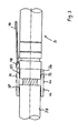
- FIGURES 1 and 2 depict a cable connector 2 of the present invention in the form of an elongate conduit which may be, for example, a tube, pipe or any other similarly shaped device capable of fluid transport.
- the cable connector has an exterior 4, ends 6 and 7, and an interior 8 that is divided by an interior wall 10 into two hollow portions 12 and 14.
- the hollow portions 12 and 14 are each sized and shaped to receive an end of an electrical cable or cable section. A portion of a cable that has been stripped to remove the outer insulation from the cable is inserted into each hollow portion.
- Crimping guides 28 and 30 are provided on the exterior 4 of the connector to demark the appropriate location of crimping.
- Strain relief grooves 24 and 26 are located on the exterior 4 of the cable connector adjacent the crimping guides 28 and 30, respectively, and provide relief from strain forces generated as the cable connector is crimped.
- Two orifices 16 and 18 are provided in the ends 6 and 7 of the cable connector 2 to allow a cable damage repair chemical to be injected into the cable.
- Orifice 16 communicates with the hollow portion 12 of the cable connector
- orifice 18 communicates with the hollow portion 14.
- Each orifice 16 and 18 is preferably threaded to allow the orifice to be closed after chemicals have been pumped through the orifice, as described in further detail below.
- interior circumferential grooves 20 and 22 are formed around the interior of the hollow portions 12 and 14, respectively.
- the interior grooves 20 and 22 preferably intersect orifice 16 and orifice 18, respectively, to channel chemicals pumped through the orifice around the exterior of each cable contained in the ends of the cable connector.
- the exterior 4 of the cable connector 2 is also formed with circumferential seal grooves 32 and 34 adjacent the ends 6 and 7 of the connector, respectively.
- the seal grooves are sized to receive an O-ring or other seal known in the art, to optionally provide an enhanced seal between the cable connector 2 and electrical cable sections or cables, as described in further detail below.
- FIGURE 3 shows a first embodiment for attachment of the cable connector 2 to an electrical cable in which an O-ring or other seal is not employed in seal groove 32, and seal groove 32 is not present.
- broad band seals 33 can be employed between sheath 36 and connector 2 and cable 38.
- sheath 36 itself, may provide a tight enough seal without seals if sheath 36 is, for example, vinyl.
- an adhesive can be employed between sheath 36 and connector 2 and cable 38. As shown in FIGURE 3 , sheath 36 is initially placed over the end 6 of the cable connector 2.
- the sheath 36 is preferably comprised of a liquid tight material that can be either resilient or can have heat-shrink properties and can be, for example, rubber, vinyl, polyethylene, or nylon.
- Cable 38 that is comprised of, for example, cable insulation 40 and cable strands 42, is inserted into the end of the cable connector and secured in the hollow portion 12 by crimping the connector.
- Sheath connectors 44 which may be, for example, steel bands or clamps, or other material with high tensile strength, are placed around the sheath 36 to secure the sheath 36 at the juncture of the end 6 of cable connector 2 and the cable insulation 40 of the cable 38.
- cable water-damage repair chemicals such as, for example, a silicone fluid (CABLECURE ® ), may be injected into the cable 38.
- the repair chemicals are supplied from a pressure source known in the art through a tube 46 in communication with a tube fitting 48.
- Tube fitting 48 is preferably threadedly mateable with orifices 16 and 18, and preferably also functions as a closure device.
- the silicone fluid flows through orifice 16, into hollow portion 12, where it contacts cable strands 42 of cable 38, passes out of end 6 of elongate conduit 2 and into cable 38 for a predetermined distance.
- the tube 46 is removed.
- the tube fitting 48 remains in the orifices 16 and 18 and is plugged to the orifices 16 and 18.
- FIGURE 3 only shows and describes the chemical repair and electrical connection of a single cable 38 to the cable connector 2 at end 6, it is understood that a second cable can be attached at end 7 of the cable connector 2 for a similar chemical repair and electrical connection.
- the present invention encompasses both a cable connector 2 having only an end 6 and not an end 7 to secure only a single cable 38 with some other known electrically conductive connection to other devices in place of end 7, as well as a cable connector 2 having both an end 6 and an end 7 to secure, repair and electrically connect two cables 38.
- FIGURE 4 a second embodiment of the present invention is shown which is similar to the first embodiment of the present invention of FIGURE 3 and in which the same element numbers are used as in FIGURE 3 to describe like elements.
- the primary difference between the first embodiment of FIGURE 3 and the second embodiment of FIGURE 4 is that in the second embodiment of FIGURE 4 , an O-ring or seal 50 is located in the seal groove 32 adjacent the end 6 of the cable connector 2.
- the seal 50 is therefore located between the end 6 of the cable connector 2 and the sheath 36.
- a second seal 50 is also located between the sheath 36 and the cable insulation 40 of cable 38.
- sheath 36 is bowed such that concave portions are present for the placement of seals 50 between sheath 36 and cable 38, and between sheath 36 and the end 6 of the cable connector 2, respectively. Additionally, sheath 36 is bowed such that a convex center portion provides additional closure at the juncture of attachment of cable 38 in end 6 of the cable connector 2.
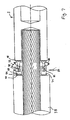
- FIGURES 5 and 6 a third embodiment of the present invention is shown in which the same element numbers are used as are used in FIGURE 3 , which shows the first embodiment, to describe like elements.
- the primary difference between the first embodiment of FIGURE 3 and the third embodiment of FIGURES 5 and 6 is that the third embodiment of FIGURES 5 and 6 does not employ a sheath 36 at the juncture of the end 6 of cable connector 2 and the insulation 40 of the cable 38. Instead, a threaded seal 52 is located at the juncture of end 6 of cable connector 2 and insulation 40 of cable 38.
- Threaded seal 52 is comprised of a preferably annular inner seal member 54 having an exterior surface 56. On exterior surface 56 are threads 58.
- Compression ring 59 is located on inner seal member 54 with O-ring seal 57 located therebetween.
- Threaded seal 52 also includes outer seal member 60 which is preferably annular, and which has threads 64 thereon that are mateable with threads 58 of inner seal member 54.
- Elastomeric packing 68 is located between the junctures of both compression ring 59 and inner seal member 54 with insulation 40 of cable 38, and elastomeric packing 69 is located between inner seal member 54 and end 6 of cable connector 2.
- Inner seal member 54 has a passageway 70 therethrough for passage of cable water-damaged repair chemicals through threaded seal 52 and into contact with cable strands 42 of cable 38, in a manner described above for the first embodiment of the present invention.
- connector 2 can be a connector known in the art, with the elements of the third embodiment being located over cable strands 42 and between insulation 40 and connector 2.
- FIGURE 7 a fourth embodiment of the present invention is shown which includes elements described in the first embodiment of the present invention of FIGURE 3 , these elements having like element numbers to those in the first embodiment of FIGURE 3 .
- spring seal 72 is employed in the fourth embodiment of the invention of FIGURE 7 .
- Spring seal 72 is comprised of a spring receptacle portion 74 which is preferably annular in shape and which has a hollow interior 76 which is sized to receive spring 78.
- Spring seal 72 also includes annular elongate portion 80 which is mateable with hollow interior 76 of spring receptacle portion 74 to compress spring 78 when spring seal 72 is secured.
- Hole 82 passes through spring receptacle portion 74, communicates with hollow interior 76 thereof, and is coaxially aligned with hole 84 when elongate portion 80 is inserted into hollow interior 76 of spring receptacle portion 74.
- Pin 86 is adapted to pass through hole 82 of spring receptacle portion 74 and hole 84 of elongate portion 80 to lock elongate portion 80 in spring receptacle portion 74.
- O-ring-type seal 88 is present between elongate portion 80 and spring receptacle portion 74 in hollow interior 76 thereof; O-ring-type seal 90 is present between spring receptacle portion 74 and insulation 40 of cable 38, and O-ring-type seal 92 is present between elongate portion 80 and end 6 of cable connector 2 to provide a fluid-tight environment through which cable repair chemicals can pass.
- Passageway 94 is located through spring receptacle portion 74 to allow cable repair chemicals to pass through spring seal 72 and contact cable strands 42 of cable 38.
- FIGURE 8 a fifth embodiment of the present invention is shown having elements that are also present in the first embodiment of the present invention of FIGURE 3 , these like elements having the same element numbers as those used in the first embodiment of FIGURE 3 .
- a fluid-tight connection between cable 38 and connector 2 is created by cable shoulder 98 which is defined by first portion 100 of insulation 40 having a standard outside diameter and by a second portion 102 of insulation 40 having an outside diameter less than the outside diameter of first portion 100 of insulation 40 of cable 38.
- a seat 104 in hollow portion 12 of interior 8 of connector 2 is mateable with shoulder 98. More specifically, seat 104 includes first portion 106 that has an inside diameter less than the outside diameter of second portion 102 of insulation 40, and also includes a second portion 108 that has an inside diameter greater than the outside diameter of second portion 102 of insulation 40.
- second portion 102 of insulation 40 is insertable into second portion 108 of hollow portion 12, but second portion 102 of insulation 40 has an outside diameter too great to clear the lesser inside diameter of first portion 106 of hollow portion 12 such that shoulder 98 of insulation 40 mates with seat 104 of hollow portion 12 and abuts against end 6 of connector 2.
- annular seal 110 for example, an O-ring or the like, can be located between second portion 108 of hollow portion 12 and second portion 102 of insulation 40.
- FIGURE 9 a sixth embodiment of the present invention is shown having elements that are also present in the first embodiment of the present invention of FIGURE 3 , these like elements having the same element numbers as those used in the first embodiment of FIGURE 3 .
- a configuration is shown which allows cable connector 2 to pass cable repair chemicals therethrough such that these chemicals are originated only at one end of cable connector 2, i.e., end 6, and not at both ends 6 and 7 of cable connector 2, whereby cable repair chemicals flow in a single direction through cable connector 2.
- the above configuration is useful when cable connector 2 is located remotely from the initial injection point of the cable repair chemicals into cable 38.
- tube 96 is employed to connect tube fitting 48 of end 6 with tube fitting 48 of end 7 such that cable repair chemicals entering end 6 of cable connector 2 are not blocked by interior wall 10, but instead pass through tube fitting 48 of end 6, through tube 96, through tube fitting 48 of end 7, and out of end 7 into the other portion of cable 38 which is joined by cable connector 2.
- the subject invention can be used in low, medium, or high voltage environments, and is also applicable for the use of air drying techniques for cable water contamination in addition to the above described water damage repair chemical application.
Landscapes
- Processing Of Terminals (AREA)
- Infusion, Injection, And Reservoir Apparatuses (AREA)
- Catching Or Destruction (AREA)
- Paper (AREA)
Abstract
Description
- The invention relates to electrical cable connectors, such as splices; and further relates to conduits, or the like, for injection of fluid into the interior of electrical cables.
- Beginning in the post-war construction boom of the late 1950s and early 1960s, overhead electrical cable lines were recognized as an eyesore. Underground electrical cable technology was developed and implemented due to its aesthetic advantages and reliability. Underground electrical cable, a medium voltage cable that carries from 5,000 volts to 35,000 volts with an average voltage of 15,000 volts, initially employed high molecular weight polyethylene (HMWPE) polymer as the insulation of choice due to its low cost and ease of manufacturing. Subsequently, cross-linked polyethylene (XLPE) and ethylene propylene rubber (EPR) replaced high molecular weight polyethylene as the insulation. More recently, a water damage retardant formulation has also been included in these newer types of insulation.
- Underground electrical cable was initially touted as having a useful life of from 25 to 40 years. However, the useful life of underground cable has rarely exceeded 20 years, and has occasionally been as short as 10 to 12 years. Catastrophic failure of older HMWPE, XLPE, and EPR cable is now beginning to occur due to water damage known as "water trees." Water trees are formed in the polymer when medium to high voltage alternating current is applied to a polymeric dielectric (insulator) in the presence of liquid water and ions. As water trees grow, they compromise the dielectric properties of the polymer until the insulation fails. Many large water trees initiate at the site of an imperfection or contaminant, but contamination is not a necessary condition for water trees to propagate.
- Water tree growth can be eliminated or retarded by removing or minimizing the water or ions, or by reducing the voltage stress. Voltage stress can be minimized by employing thicker insulation. "Clean room" manufacturing processes can be used to both eliminate ion sources and minimize defects or contaminants that function as water tree growth sites. Another approach is to change the character of the dielectric, either through adding water tree retardant chemicals to polyethylene or by using more expensive, but water tree resistant, plastics or rubbers. All of these approaches have merit, but only address the performance of electrical cable yet to be installed.
- For electrical cables already underground, the options are more limited. First, the entire failing electrical cable can be replaced, but the cost is often prohibitive. Second, the points of failures due to water tree propagation can be excised and the removed portions replaced with a splice. Unfortunately, since water trees are not identifiable until after cable failure occurs, splicing after cable failure results in a power interruption to the electric utility customers. Third, the cable can be dried with a desiccant fluid such as nitrogen in order to remove the water that initiates the water tree. While this approach improves the dielectric properties of the underground cable, it requires perpetual maintenance to replace large and unsightly nitrogen bottles that remain coupled to the cable.
- A more promising approach to retard failure of underground cable is to inject a silicone fluid such as, for example, CABLECURE®, into the electrical cable conductor strands. CABLECURE reacts with water in the underground cable and polymerizes to form a water tree retardant that is more advanced than those used in the manufacture of modem cables. The dielectric properties of the cable are not only stabilized by CABLECURE, but actually improved dramatically.
- However, the devices and methods used to treat underground electrical cables with CABLECURE do have drawbacks. Different methodologies are employed depending upon the type of cable being treated. There are two main classes of cables, underground residential distribution (URD) cables which are relatively small cables, and feeder cables, which are larger cables which often supply the URD cables.
- Regarding the treatment of feeder cables with CABLECURE, a major problem is the ability of splices which are often encountered in the feeder cable to hold the pressure required to inject perhaps miles of the feeder cable with CABLECURE. The larger the overall cable diameter, the larger the splice, and the higher the hoop forces created by the pressurization of the cable cavity. Due to the large diameter of feeder cables, there is seldom sufficient hoop strength in the typical splices to withstand the basic vapor pressure of the CABLECURE without leaking, not to mention the increased pressurization required to transport the CABLECURE along the miles of feeder cable. A leak of CABLECURE in the splice can create a contaminated path along the splice interface which may lead to eventual failure of the splice.
- To avoid the problem of CABLECURE leaking at splices, one of two approaches have been employed for injection of CABLECURE into feeder cables. First, the splice can be reinforced with clamps or other devices to increase its hoop strength. However, this approach is limited because the force necessarily applied by the hose clamps or other reinforcement devices on the splice is so large that there is substantial deformation of the rubber material used to make the splice. The deformation compromises the geometrical and electrical integrity of the splice and thus provides only a slight increase in injection pressure tolerance. A second approach is to remove the splice prior to injecting the two separated segments of the electrical cable with CABLECURE, then injecting CABLECURE, and finally injecting a second damming chemical compound into the two electrical cable segments that physically blocks the migration of the CABLECURE into a new splice that is applied to the two cable segments after the CABLECURE treatment has been completed. An example of a damming compound is a combination of dimethylsilicone polymers with vinyl cross-linker and a suitable catalyst. In addition to low viscosity and quick cure times, a damming fluid must be compatible with all cables, splices and other components. Drawbacks with the above method of employing a damming compound include the additional cost of the expensive damming compound, the necessity to install a new splice, and the possibility that the CABLECURE may compromise the structural integrity of the new splice if the physical partition formed by the damming compound fails.
- Further, it has been learned that injection of damming compounds into even short lengths near the end of a cable can create transient discontinuities in the penetration of the dielectric enhancement fluid. These discontinuities of penetration create discontinuous treatment, which at a minimum leaves some small section of the cable untreated for a longer period of time, increasing the risk of a post treatment dielectric failure. Further, there is a potential that these discontinuities can even lead to local electrical stress increases which may contribute to a failure in the region where the dam interferes with uniform penetration. Since the point of injecting cable is to increase its reliability and mitigate its proclivity to fail, the use of either reinforcing devices or damming compounds to handle sufficient injection, vapor and elevation-induced pressure are not ideal solutions.
- CABLECURE injection can also be employed to treat water tree damage in URD cables. Since the diameter of the URD cables is less than that of feeder cables, the splices in URD cables can withstand the vapor pressure of CABLECURE. Additionally, due to the typically shorter lengths of the URD cables, a lower pressure (0-30 psig) than the pressure employed in feeder cables is required to transport the CABLECURE through the URD cable; therefore, the splices in the URD cable are not subjected to the moderate pressures (30-120 psig) desired to inject typically longer feeder cable and their integral splices. However, because an URD cable does not have enough interstitial volume in the strands of the cable to hold sufficient CABLECURE for maximum dielectric performance, URD cables require an extended soak period of 60 days or more to allow for additional CABLECURE to diffuse from the cable strands into the polyethylene. When very long URD cables or URD cables with large elevation changes are encountered, moderate to medium (120-350 psig) pressure injection of CABLECURE may be required. The moderate to medium pressure addition of CABLECURE to an URD cable therefore necessitates removing the splices during the treatment of the cable, followed by adding new splices after the treatment.
- A need thus exists for devices and methods whereby expensive damming compounds are not required to block the contact of repair chemicals with the replacement splice in feeder cables.
- A need also exists for devices and methods in which both a separate conduit for injecting CABLECURE into a feeder cable as well as a separate replacement splice are not required.
- A further need exists for devices and methods in which repair chemicals can be injected into URD cables at moderate to medium pressures without compromising the structural integrity of splices.
-
US 477376 has been used to identify the pre-characterising portion of the independent claim. - A device for repairing and electrically connecting, in a first embodiment, at least two sections of electrical cable includes an elongate conduit, for example, a tube having two open ends that are each adapted to receive an end of an electrical cable section. The elongate conduit has an interior wall longitudinally dividing the elongate conduit into two portions, each portion having a hollow interior for containing the end of one of the two electrical cable sections. The elongate conduit also has an orifice in each of the two portions communicating with the hollow interior of that portion. A closure device, such as a threaded plug, is mateable with each orifice. Additionally, the device further comprises a fluid-tight seal over the juncture of each electrical cable section end and at each end of the elongate conduit. In operation, water damage to the electrical cable portions is repaired by securing an end of an electrical cable section in the hollow interior of each of the two portions of the elongate conduit, sealing those junctures, and passing repairing chemicals through the orifices in the elongate conduit, into the hollow interior of each of the two portions of the elongate conduit, and into the interior of the sections of the electrical cable. The secondary addition of damming chemicals through the elongate conduit and into the electrical cable sections is not required. The sections of electrical cable are electrically connected when secured in the hollow interior of the two portions of the elongate conduit; therefore, the elongate conduit also functions as a splice electrically joining the two wire sections.
- Preferably, the elongate conduit further comprises an annular groove adjacent each elongate conduit end, on the hollow interior and intersecting the orifice to augment fluid flow. The elongate conduit also preferably comprises an annular groove adjacent each elongate conduit end and around the elongate conduit exterior for strain relief. Most preferably, the elongate conduit also comprises an annular groove adjacent each elongate conduit end and around the elongate conduit exterior that is sized to receive an interior seal locatable between the elongate conduit and the fluid-tight sheath.
- In another embodiment of the present invention, an end of a single electrical cable is secured to an end of an elongate conduit having a hollow interior that contains the electrical cable end. A single orifice communicates with the hollow interior for passage of chemicals therebetween. A single fluid-tight seal is located over the juncture of the single electrical cable end and end of the elongate conduit.
- According to a first aspect of the invention, we provide a device for repairing and electrically connecting a section of electrical cable having an end and an interior, the device comprising:
- an elongate conduit having an open end that is adapted to receive an end of an electrical cable section, having an exterior, and having a hollow interior integrally formed within said conduit for receiving said end of said electrical cable section, the elongate conduit having an orifice communicating with the hollow interior and a closure device for the orifice, the elongate conduit having a seal adjacent the open end of the elongate conduit such that water damage to electrical cable is repaired by securing an end of an electrical cable section that is secured in the hollow interior of the elongate conduit to form a juncture and the seal seals the juncture of the electrical cable section end and the elongate conduit open end, wherein repair chemicals are passed through the orifice in the elongate conduit, into the hollow interior of the elongate conduit,
- characterized in that the electrical cable section is electrically connectable to an electrically conductive assembly without physically contacting the assembly when secured in the hollow interior of the elongate conduit,
- wherein repair chemicals are passed into the interior of the electrical cable.
- The seal may comprise a fluid-tight sheath over the juncture of the electrical cable section end and the end of the elongate conduit.
- The foregoing aspects and many of the attendant advantages of this invention will become more readily appreciated as the same becomes better understood by reference to the following detailed description, when taken in conjunction with the accompanying drawings, wherein:
-
FIGURE 1 is a perspective view, partially exposed, of a cable connector of the present invention; -
FIGURE 2 is a side view of the cable connector of the present invention; ' -
FIGURE 3 is a side view of a first embodiment of the cable connector of the present invention secured to a cable for injection of cable damage repair chemicals therethrough and for electrical connection of the cable with a second cable; -
FIGURE 4 is a side view of a second embodiment of the cable connector of the present invention secured to a cable for injection of cable damage repair chemicals therethrough and for electrical connection of the cable with a second cable; -
FIGURE 5 is a side view, partially exposed, of a third embodiment of the cable connector of the present invention secured to a cable for injection of cable damage repair chemicals therethrough and for electrical connection of the cable with a second cable; -
FIGURE 6 is a detail view ofFIGURE 5 ; -
FIGURE 7 is a side view, partially exposed, of a fourth embodiment of the cable connector of the present invention secured to a cable for injection of cable damage repair chemicals therethrough and for electrical connection of the cable with a second cable; -
FIGURE 8 is a side view of a fifth embodiment of the cable connector of the present invention secured to a cable for injection of cable damage repair chemicals therethrough and for electrical connection of the cable with a second cable; and -
FIGURE 9 is a side view of a sixth embodiment of the cable connector of the present invention secured to a cable for injection of cable damage repair chemicals therethrough and for electrical connection of the cable with a second cable. -
FIGURES 1 and2 depict acable connector 2 of the present invention in the form of an elongate conduit which may be, for example, a tube, pipe or any other similarly shaped device capable of fluid transport. The cable connector has an exterior 4, ends 6 and 7, and an interior 8 that is divided by aninterior wall 10 into twohollow portions hollow portions end Strain relief grooves guides - Two
orifices ends cable connector 2 to allow a cable damage repair chemical to be injected into the cable.Orifice 16 communicates with thehollow portion 12 of the cable connector, andorifice 18 communicates with thehollow portion 14. Eachorifice interior 8 of the cable connector, interiorcircumferential grooves hollow portions interior grooves orifice 16 andorifice 18, respectively, to channel chemicals pumped through the orifice around the exterior of each cable contained in the ends of the cable connector. - The exterior 4 of the
cable connector 2 is also formed withcircumferential seal grooves ends cable connector 2 and electrical cable sections or cables, as described in further detail below. -
FIGURE 3 shows a first embodiment for attachment of thecable connector 2 to an electrical cable in which an O-ring or other seal is not employed inseal groove 32, and sealgroove 32 is not present. Instead, broad band seals 33 can be employed betweensheath 36 andconnector 2 andcable 38. Alternatively,sheath 36, itself, may provide a tight enough seal without seals ifsheath 36 is, for example, vinyl. Also, instead of broad band seals 33, an adhesive can be employed betweensheath 36 andconnector 2 andcable 38. As shown inFIGURE 3 ,sheath 36 is initially placed over theend 6 of thecable connector 2. Thesheath 36 is preferably comprised of a liquid tight material that can be either resilient or can have heat-shrink properties and can be, for example, rubber, vinyl, polyethylene, or nylon.Cable 38 that is comprised of, for example,cable insulation 40 andcable strands 42, is inserted into the end of the cable connector and secured in thehollow portion 12 by crimping the connector.Sheath connectors 44, which may be, for example, steel bands or clamps, or other material with high tensile strength, are placed around thesheath 36 to secure thesheath 36 at the juncture of theend 6 ofcable connector 2 and thecable insulation 40 of thecable 38. - Once the
cable 38 is secured to thecable connector 2, cable water-damage repair chemicals, such as, for example, a silicone fluid (CABLECURE®), may be injected into thecable 38. The repair chemicals are supplied from a pressure source known in the art through atube 46 in communication with atube fitting 48. Tube fitting 48 is preferably threadedly mateable withorifices FIGURE 3 , after passing through tube fitting 48, the silicone fluid flows throughorifice 16, intohollow portion 12, where itcontacts cable strands 42 ofcable 38, passes out ofend 6 ofelongate conduit 2 and intocable 38 for a predetermined distance. After sufficient silicone fluid has been injected into the cable thetube 46 is removed. The tube fitting 48 remains in theorifices orifices - After termination of cable water-damage repair chemical treatment and after the
tube 46 is detached from the tube fitting 48, the electrical cable or cable sections are electrically energized. It will be appreciated that because thecable connector 2 is electrically conductive,cable 38 is electrically connectable to any other cable also attached to the cable connector. Note that whileFIGURE 3 only shows and describes the chemical repair and electrical connection of asingle cable 38 to thecable connector 2 atend 6, it is understood that a second cable can be attached atend 7 of thecable connector 2 for a similar chemical repair and electrical connection. In other words, the present invention encompasses both acable connector 2 having only anend 6 and not anend 7 to secure only asingle cable 38 with some other known electrically conductive connection to other devices in place ofend 7, as well as acable connector 2 having both anend 6 and anend 7 to secure, repair and electrically connect twocables 38. - Referring to
FIGURE 4 , a second embodiment of the present invention is shown which is similar to the first embodiment of the present invention ofFIGURE 3 and in which the same element numbers are used as inFIGURE 3 to describe like elements. The primary difference between the first embodiment ofFIGURE 3 and the second embodiment ofFIGURE 4 is that in the second embodiment ofFIGURE 4 , an O-ring or seal 50 is located in theseal groove 32 adjacent theend 6 of thecable connector 2. Theseal 50 is therefore located between theend 6 of thecable connector 2 and thesheath 36. Asecond seal 50 is also located between thesheath 36 and thecable insulation 40 ofcable 38. Additionally,sheath 36 is bowed such that concave portions are present for the placement ofseals 50 betweensheath 36 andcable 38, and betweensheath 36 and theend 6 of thecable connector 2, respectively. Additionally,sheath 36 is bowed such that a convex center portion provides additional closure at the juncture of attachment ofcable 38 inend 6 of thecable connector 2. - Referring to
FIGURES 5 and 6 , a third embodiment of the present invention is shown in which the same element numbers are used as are used inFIGURE 3 , which shows the first embodiment, to describe like elements. The primary difference between the first embodiment ofFIGURE 3 and the third embodiment ofFIGURES 5 and 6 is that the third embodiment ofFIGURES 5 and 6 does not employ asheath 36 at the juncture of theend 6 ofcable connector 2 and theinsulation 40 of thecable 38. Instead, a threadedseal 52 is located at the juncture ofend 6 ofcable connector 2 andinsulation 40 ofcable 38. Threadedseal 52 is comprised of a preferably annularinner seal member 54 having anexterior surface 56. Onexterior surface 56 arethreads 58.Compression ring 59 is located oninner seal member 54 with O-ring seal 57 located therebetween. Threadedseal 52 also includes outer seal member 60 which is preferably annular, and which has threads 64 thereon that are mateable withthreads 58 ofinner seal member 54. Elastomeric packing 68 is located between the junctures of bothcompression ring 59 andinner seal member 54 withinsulation 40 ofcable 38, and elastomeric packing 69 is located betweeninner seal member 54 andend 6 ofcable connector 2.Inner seal member 54 has apassageway 70 therethrough for passage of cable water-damaged repair chemicals through threadedseal 52 and into contact withcable strands 42 ofcable 38, in a manner described above for the first embodiment of the present invention. In operation, threaded interconnection ofinner seal member 54 and outer seal member 60 imparts an axial force throughcompression ring 59 and into elastomeric packing 68 whileinner seal member 54 imparts an opposite axial force onelastomeric packing 69 to form a complete seal. Note that in the third embodiment,connector 2 can be a connector known in the art, with the elements of the third embodiment being located overcable strands 42 and betweeninsulation 40 andconnector 2. - Now referring to
FIGURE 7 , a fourth embodiment of the present invention is shown which includes elements described in the first embodiment of the present invention ofFIGURE 3 , these elements having like element numbers to those in the first embodiment ofFIGURE 3 . Unlike the first embodiment of the present invention ofFIGURE 3 in whichsheath 36 is located at the juncture of theend 6 ofcable connector 2 andinsulation 40 ofcable 38, in the fourth embodiment of the invention ofFIGURE 7 ,spring seal 72 is employed.Spring seal 72 is comprised of aspring receptacle portion 74 which is preferably annular in shape and which has a hollow interior 76 which is sized to receivespring 78.Spring seal 72 also includes annular elongate portion 80 which is mateable with hollow interior 76 ofspring receptacle portion 74 to compressspring 78 whenspring seal 72 is secured.Hole 82 passes throughspring receptacle portion 74, communicates with hollow interior 76 thereof, and is coaxially aligned with hole 84 when elongate portion 80 is inserted into hollow interior 76 ofspring receptacle portion 74. Pin 86 is adapted to pass throughhole 82 ofspring receptacle portion 74 and hole 84 of elongate portion 80 to lock elongate portion 80 inspring receptacle portion 74. O-ring-type seal 88 is present between elongate portion 80 andspring receptacle portion 74 in hollow interior 76 thereof; O-ring-type seal 90 is present betweenspring receptacle portion 74 andinsulation 40 ofcable 38, and O-ring-type seal 92 is present between elongate portion 80 andend 6 ofcable connector 2 to provide a fluid-tight environment through which cable repair chemicals can pass.Passageway 94 is located throughspring receptacle portion 74 to allow cable repair chemicals to pass throughspring seal 72 andcontact cable strands 42 ofcable 38. - Referring to
FIGURE 8 , a fifth embodiment of the present invention is shown having elements that are also present in the first embodiment of the present invention ofFIGURE 3 , these like elements having the same element numbers as those used in the first embodiment ofFIGURE 3 . Unlike the first embodiment of the present invention ofFIGURE 3 in whichsheath 36 is located at the juncture of theend 6 ofcable connector 2 andinsulation 40 ofcable 38, in the fifth embodiment ofFIGURE 8 , a fluid-tight connection betweencable 38 andconnector 2 is created bycable shoulder 98 which is defined byfirst portion 100 ofinsulation 40 having a standard outside diameter and by asecond portion 102 ofinsulation 40 having an outside diameter less than the outside diameter offirst portion 100 ofinsulation 40 ofcable 38. Aseat 104 inhollow portion 12 ofinterior 8 ofconnector 2 is mateable withshoulder 98. More specifically,seat 104 includesfirst portion 106 that has an inside diameter less than the outside diameter ofsecond portion 102 ofinsulation 40, and also includes asecond portion 108 that has an inside diameter greater than the outside diameter ofsecond portion 102 ofinsulation 40. Thus,second portion 102 ofinsulation 40 is insertable intosecond portion 108 ofhollow portion 12, butsecond portion 102 ofinsulation 40 has an outside diameter too great to clear the lesser inside diameter offirst portion 106 ofhollow portion 12 such thatshoulder 98 ofinsulation 40 mates withseat 104 ofhollow portion 12 and abuts againstend 6 ofconnector 2. To further ensure a fluid-tight fit betweencable 38 andconnector 2,annular seal 110, for example, an O-ring or the like, can be located betweensecond portion 108 ofhollow portion 12 andsecond portion 102 ofinsulation 40. - Referring to
FIGURE 9 , a sixth embodiment of the present invention is shown having elements that are also present in the first embodiment of the present invention ofFIGURE 3 , these like elements having the same element numbers as those used in the first embodiment ofFIGURE 3 . In the sixth embodiment ofFIGURE 9 , a configuration is shown which allowscable connector 2 to pass cable repair chemicals therethrough such that these chemicals are originated only at one end ofcable connector 2, i.e.,end 6, and not at both ends 6 and 7 ofcable connector 2, whereby cable repair chemicals flow in a single direction throughcable connector 2. The above configuration is useful whencable connector 2 is located remotely from the initial injection point of the cable repair chemicals intocable 38. Thus, as shown inFIGURE 9 ,tube 96 is employed to connect tube fitting 48 ofend 6 with tube fitting 48 ofend 7 such that cable repairchemicals entering end 6 ofcable connector 2 are not blocked byinterior wall 10, but instead pass through tube fitting 48 ofend 6, throughtube 96, through tube fitting 48 ofend 7, and out ofend 7 into the other portion ofcable 38 which is joined bycable connector 2. - Those skilled in the art will recognize that the subject invention can be used in low, medium, or high voltage environments, and is also applicable for the use of air drying techniques for cable water contamination in addition to the above described water damage repair chemical application.
- While the preferred embodiments of the invention have been illustrated and described, it will be appreciated that various changes can be made therein without departing from the scope of the invention as defined by the claims.
Claims (2)
- A device for repairing and electrically connecting a section of electrical cable (38) having an end and an interior, the device comprising:an elongate conduit (2) having an open end (6) that is adapted to receive an end of an electrical cable section, having an exterior (4), and having a hollow interior (8) integrally formed within said conduit for receiving said end of said electrical cable section, the elongate conduit having an orifice (16) communicating with the hollow interior (8) and a closure device for the orifice (16), the elongate conduit having a seal (33) adjacent the open end of the elongate conduit such that water damage to electrical cable is repaired by securing an end of an electrical cable section (38) that is secured in the hollow interior (8) of the elongate conduit to form a juncture and the seal (33) seals the juncture of the electrical cable section end and the elongate conduit open end, wherein repair chemicals are passed through the orifice (16) in the elongate conduit, into the hollow interior (18) of the elongate conduit (12),characterized in that the electrical cable section (38) is electrically connectable to an electrically conductive assembly without physically contacting the assembly when secured in the hollow interior (8) of the elongate conduit, wherein repair chemicals are passed into the interior of the electrical cable.
- The device of Claim 1 wherein the seal (33) comprises a fluid-tight sheath (36) over the juncture of the electrical cable section (38) end and the end of the elongate conduit (2).
Applications Claiming Priority (2)
| Application Number | Priority Date | Filing Date | Title |
|---|---|---|---|
| US08/799,547 US5907128A (en) | 1997-02-13 | 1997-02-13 | Cable connector with fluid injection port |
| EP98906483A EP1008217B1 (en) | 1997-02-13 | 1998-02-12 | Cable connector with fluid injection port |
Related Parent Applications (2)
| Application Number | Title | Priority Date | Filing Date |
|---|---|---|---|
| EP98906483A Division EP1008217B1 (en) | 1997-02-13 | 1998-02-12 | Cable connector with fluid injection port |
| EP98906483.7 Division | 1998-08-20 |
Publications (3)
| Publication Number | Publication Date |
|---|---|
| EP1617536A2 EP1617536A2 (en) | 2006-01-18 |
| EP1617536A3 EP1617536A3 (en) | 2008-07-02 |
| EP1617536B1 true EP1617536B1 (en) | 2011-12-21 |
Family
ID=25176185
Family Applications (2)
| Application Number | Title | Priority Date | Filing Date |
|---|---|---|---|
| EP05020059A Expired - Lifetime EP1617536B1 (en) | 1997-02-13 | 1998-02-12 | Cable connector with fluid injection port |
| EP98906483A Expired - Lifetime EP1008217B1 (en) | 1997-02-13 | 1998-02-12 | Cable connector with fluid injection port |
Family Applications After (1)
| Application Number | Title | Priority Date | Filing Date |
|---|---|---|---|
| EP98906483A Expired - Lifetime EP1008217B1 (en) | 1997-02-13 | 1998-02-12 | Cable connector with fluid injection port |
Country Status (10)
| Country | Link |
|---|---|
| US (1) | US5907128A (en) |
| EP (2) | EP1617536B1 (en) |
| AT (2) | ATE328387T1 (en) |
| AU (1) | AU6169798A (en) |
| CA (1) | CA2280899C (en) |
| DE (1) | DE69834730T2 (en) |
| DK (1) | DK1008217T3 (en) |
| ES (1) | ES2267177T3 (en) |
| PT (1) | PT1008217E (en) |
| WO (1) | WO1998036482A1 (en) |
Families Citing this family (30)
| Publication number | Priority date | Publication date | Assignee | Title |
|---|---|---|---|---|
| NZ508348A (en) * | 1998-05-27 | 2003-11-28 | Utilx Corp | Cable fluid injection sleeve |
| EP1222723B1 (en) | 1999-10-11 | 2007-03-07 | Utilx Corporation | Connections and terminations for cables |
| US6517366B2 (en) | 2000-12-06 | 2003-02-11 | Utilx Corporation | Method and apparatus for blocking pathways between a power cable and the environment |
| AU2005218559B2 (en) * | 2004-03-01 | 2010-09-23 | Novinium, Inc. | Method for treating electrical cable at sustained elevated pressure |
| EP1744866B1 (en) * | 2004-03-01 | 2012-08-08 | Novinium, Inc. | Method for selecting formulations to treat electrical cables |
| CA2557169C (en) * | 2004-03-01 | 2014-07-15 | Novinium, Inc. | High-pressure power cable connector |
| US7146745B2 (en) * | 2004-05-27 | 2006-12-12 | Kent Thomas G | Apparatus and process for servicing underground electrical power distribution cables |
| EP1755723B1 (en) * | 2004-06-04 | 2009-10-21 | Radi Medical Systems Ab | Medical guidewire with sensor |
| US7331806B2 (en) * | 2004-08-25 | 2008-02-19 | Utilx Corporation | Cable connectors with internal fluid reservoirs |
| US7704087B1 (en) | 2004-09-03 | 2010-04-27 | Utilx Corporation | Check valve for charge tank |
| US7256350B2 (en) * | 2005-04-19 | 2007-08-14 | Utilx Corporation | Fluid reservoir for a cable span |
| US20060231283A1 (en) * | 2005-04-19 | 2006-10-19 | Stagi William R | Cable connector having fluid reservoir |
| US7344396B2 (en) * | 2005-08-23 | 2008-03-18 | Utilx Corporation | Cable connection assembly |
| US7544105B2 (en) * | 2005-08-23 | 2009-06-09 | Utilx Corporation | Cable and cable connection assembly |
| US7658808B2 (en) * | 2005-08-30 | 2010-02-09 | Novinium, Inc. | Method for extending long-term electrical power cable performance |
| US7353601B1 (en) | 2005-08-30 | 2008-04-08 | Novinium, Inc. | Integrated method for restoring electrical power cable |
| US7538274B2 (en) * | 2006-01-23 | 2009-05-26 | Novinium, Inc. | Swagable high-pressure cable connectors having improved sealing means |
| US7700871B2 (en) * | 2007-01-19 | 2010-04-20 | Novinium, Inc. | Acid-catalyzed dielectric enhancement fluid and cable restoration method employing same |
| CA2618518C (en) * | 2007-11-27 | 2016-03-01 | Novinium, Inc. | Method for restoring power cables |
| US8344252B2 (en) * | 2008-08-20 | 2013-01-01 | Utilx Corporation | Cable splice connection assembly |
| US7959477B2 (en) * | 2008-08-20 | 2011-06-14 | Utilx Corporation | Cable termination connection assembly |
| US9853394B2 (en) | 2014-05-02 | 2017-12-26 | Itt Manufacturing Enterprises, Llc | Pressure-blocking feedthru with pressure-balanced cable terminations |
| US9793029B2 (en) * | 2015-01-21 | 2017-10-17 | Itt Manufacturing Enterprises Llc | Flexible, pressure-balanced cable assembly |
| US9843113B1 (en) | 2017-04-06 | 2017-12-12 | Itt Manufacturing Enterprises Llc | Crimpless electrical connectors |
| US9941622B1 (en) | 2017-04-20 | 2018-04-10 | Itt Manufacturing Enterprises Llc | Connector with sealing boot and moveable shuttle |
| US10276969B2 (en) | 2017-04-20 | 2019-04-30 | Itt Manufacturing Enterprises Llc | Connector with sealing boot and moveable shuttle |
| JP6787292B2 (en) * | 2017-10-13 | 2020-11-18 | 住友電装株式会社 | Wire harness |
| CN110189850A (en) * | 2019-04-30 | 2019-08-30 | 无锡市神光电缆有限公司 | A kind of copper core polyvinyl chloride insulation cord and preparation method thereof |
| US11841169B2 (en) * | 2020-09-17 | 2023-12-12 | Ojo, Inc. | Tracker motor support for truss foundations |
| US20250273898A1 (en) * | 2021-10-15 | 2025-08-28 | John Mezzalingua Associates, LLC | Vacuum soldered connector having an insulator with a check valve to prevent water ingress |
Family Cites Families (13)
| Publication number | Priority date | Publication date | Assignee | Title |
|---|---|---|---|---|
| US2958844A (en) * | 1955-05-02 | 1960-11-01 | Amp Inc | High voltage, high altitude bushing |
| US2938940A (en) * | 1958-04-16 | 1960-05-31 | Roy A Calendine | Cable splicing sleeve |
| GB870165A (en) * | 1958-10-16 | 1961-06-14 | British Insulated Callenders | Improvements in joints and terminations of electric cables |
| US3036147A (en) * | 1959-08-21 | 1962-05-22 | Fargo Mfg Co Inc | Connector |
| US3242255A (en) * | 1964-02-03 | 1966-03-22 | Cons Edison Co New York Inc | Cable terminal assembly |
| US3846578A (en) * | 1972-03-22 | 1974-11-05 | Phelps Dodge Ind Inc | Splice for electric cables |
| US3810078A (en) * | 1973-02-08 | 1974-05-07 | J Chordas | Compression splice for electrically coupling electrical conductors |
| GB1470049A (en) * | 1973-03-21 | 1977-04-14 | Rachem Corp | Splicing method and heat-recoverable article |
| US4477376A (en) * | 1980-03-10 | 1984-10-16 | Gold Marvin H | Castable mixture for insulating spliced high voltage cable |
| DE3041657A1 (en) * | 1980-11-05 | 1982-06-03 | HEW-Kabel Heinz Eilentropp KG, 5272 Wipperfürth | METHOD AND DEVICE FOR PRODUCING TENSILE AND PRESSURE SEAL, IN PARTICULAR TEMPERATURE-RESISTANT, CONNECTIONS FOR ELECTRICAL CABLES AND CABLES |
| DE3149048C2 (en) * | 1981-12-11 | 1989-03-16 | Kabel- Und Lackdrahtfabriken Gmbh, 6800 Mannheim | Arrangement for connecting cables |
| US5132495A (en) * | 1991-01-23 | 1992-07-21 | Homac Mfg. Company | Submersible splice cover with resilient corrugated and sections |
| US5245133A (en) * | 1991-10-15 | 1993-09-14 | Thomas & Betts Corporation | Moisture-resistant cable splice and sealing structure thereof |
-
1997
- 1997-02-13 US US08/799,547 patent/US5907128A/en not_active Expired - Lifetime
-
1998
- 1998-02-12 EP EP05020059A patent/EP1617536B1/en not_active Expired - Lifetime
- 1998-02-12 PT PT98906483T patent/PT1008217E/en unknown
- 1998-02-12 CA CA002280899A patent/CA2280899C/en not_active Expired - Fee Related
- 1998-02-12 ES ES98906483T patent/ES2267177T3/en not_active Expired - Lifetime
- 1998-02-12 DE DE69834730T patent/DE69834730T2/en not_active Expired - Lifetime
- 1998-02-12 AU AU61697/98A patent/AU6169798A/en not_active Abandoned
- 1998-02-12 EP EP98906483A patent/EP1008217B1/en not_active Expired - Lifetime
- 1998-02-12 AT AT98906483T patent/ATE328387T1/en active
- 1998-02-12 WO PCT/US1998/003016 patent/WO1998036482A1/en not_active Ceased
- 1998-02-12 DK DK98906483T patent/DK1008217T3/en active
- 1998-02-12 AT AT05020059T patent/ATE538523T1/en active
Also Published As
| Publication number | Publication date |
|---|---|
| CA2280899C (en) | 2006-05-30 |
| EP1008217B1 (en) | 2006-05-31 |
| CA2280899A1 (en) | 1998-08-20 |
| ATE538523T1 (en) | 2012-01-15 |
| DK1008217T3 (en) | 2006-10-02 |
| EP1008217A4 (en) | 2000-06-14 |
| EP1617536A3 (en) | 2008-07-02 |
| PT1008217E (en) | 2006-09-29 |
| ES2267177T3 (en) | 2007-03-01 |
| WO1998036482A1 (en) | 1998-08-20 |
| ATE328387T1 (en) | 2006-06-15 |
| EP1617536A2 (en) | 2006-01-18 |
| AU6169798A (en) | 1998-09-08 |
| US5907128A (en) | 1999-05-25 |
| DE69834730T2 (en) | 2007-06-06 |
| DE69834730D1 (en) | 2006-07-06 |
| EP1008217A1 (en) | 2000-06-14 |
Similar Documents
| Publication | Publication Date | Title |
|---|---|---|
| EP1617536B1 (en) | Cable connector with fluid injection port | |
| US20020046865A1 (en) | Cable fluid injection sleeve | |
| EP1222723B1 (en) | Connections and terminations for cables | |
| KR101005127B1 (en) | High voltage power cable connector | |
| US10522983B2 (en) | Injection electrical connector | |
| US8367931B2 (en) | Segmented decompression resistant cable splice and method of installation | |
| NZ508348A (en) | Cable fluid injection sleeve | |
| GB2327140A (en) | Adapting paper insulated lead cables for use with polymeric attachments |
Legal Events
| Date | Code | Title | Description |
|---|---|---|---|
| PUAI | Public reference made under article 153(3) epc to a published international application that has entered the european phase |
Free format text: ORIGINAL CODE: 0009012 |
|
| 17P | Request for examination filed |
Effective date: 20050928 |
|
| AC | Divisional application: reference to earlier application |
Ref document number: 1008217 Country of ref document: EP Kind code of ref document: P |
|
| AK | Designated contracting states |
Kind code of ref document: A2 Designated state(s): AT BE CH DE DK ES FI FR GB GR IE IT LI LU MC NL PT SE |
|
| AX | Request for extension of the european patent |
Extension state: AL LT LV MK RO SI |
|
| PUAL | Search report despatched |
Free format text: ORIGINAL CODE: 0009013 |
|
| AK | Designated contracting states |
Kind code of ref document: A3 Designated state(s): AT BE CH DE DK ES FI FR GB GR IE IT LI LU MC NL PT SE |
|
| AX | Request for extension of the european patent |
Extension state: AL LT LV MK RO SI |
|
| 17Q | First examination report despatched |
Effective date: 20090209 |
|
| AKX | Designation fees paid |
Designated state(s): AT BE CH DE DK ES FI FR GB GR IE IT LI LU MC NL PT SE |
|
| GRAP | Despatch of communication of intention to grant a patent |
Free format text: ORIGINAL CODE: EPIDOSNIGR1 |
|
| GRAS | Grant fee paid |
Free format text: ORIGINAL CODE: EPIDOSNIGR3 |
|
| GRAA | (expected) grant |
Free format text: ORIGINAL CODE: 0009210 |
|
| AC | Divisional application: reference to earlier application |
Ref document number: 1008217 Country of ref document: EP Kind code of ref document: P |
|
| AK | Designated contracting states |
Kind code of ref document: B1 Designated state(s): AT BE CH DE DK ES FI FR GB GR IE IT LI LU MC NL PT SE |
|
| REG | Reference to a national code |
Ref country code: GB Ref legal event code: FG4D |
|
| REG | Reference to a national code |
Ref country code: CH Ref legal event code: EP |
|
| REG | Reference to a national code |
Ref country code: AT Ref legal event code: REF Ref document number: 538523 Country of ref document: AT Kind code of ref document: T Effective date: 20120115 |
|
| REG | Reference to a national code |
Ref country code: IE Ref legal event code: FG4D |
|
| REG | Reference to a national code |
Ref country code: DE Ref legal event code: R096 Ref document number: 69842547 Country of ref document: DE Effective date: 20120301 |
|
| REG | Reference to a national code |
Ref country code: NL Ref legal event code: VDEP Effective date: 20111221 |
|
| PG25 | Lapsed in a contracting state [announced via postgrant information from national office to epo] |
Ref country code: GR Free format text: LAPSE BECAUSE OF FAILURE TO SUBMIT A TRANSLATION OF THE DESCRIPTION OR TO PAY THE FEE WITHIN THE PRESCRIBED TIME-LIMIT Effective date: 20120322 Ref country code: SE Free format text: LAPSE BECAUSE OF FAILURE TO SUBMIT A TRANSLATION OF THE DESCRIPTION OR TO PAY THE FEE WITHIN THE PRESCRIBED TIME-LIMIT Effective date: 20111221 Ref country code: NL Free format text: LAPSE BECAUSE OF FAILURE TO SUBMIT A TRANSLATION OF THE DESCRIPTION OR TO PAY THE FEE WITHIN THE PRESCRIBED TIME-LIMIT Effective date: 20111221 |
|
| PG25 | Lapsed in a contracting state [announced via postgrant information from national office to epo] |
Ref country code: BE Free format text: LAPSE BECAUSE OF FAILURE TO SUBMIT A TRANSLATION OF THE DESCRIPTION OR TO PAY THE FEE WITHIN THE PRESCRIBED TIME-LIMIT Effective date: 20111221 |
|
| PG25 | Lapsed in a contracting state [announced via postgrant information from national office to epo] |
Ref country code: PT Free format text: LAPSE BECAUSE OF FAILURE TO SUBMIT A TRANSLATION OF THE DESCRIPTION OR TO PAY THE FEE WITHIN THE PRESCRIBED TIME-LIMIT Effective date: 20120423 |
|
| REG | Reference to a national code |
Ref country code: AT Ref legal event code: MK05 Ref document number: 538523 Country of ref document: AT Kind code of ref document: T Effective date: 20111221 |
|
| PG25 | Lapsed in a contracting state [announced via postgrant information from national office to epo] |
Ref country code: MC Free format text: LAPSE BECAUSE OF NON-PAYMENT OF DUE FEES Effective date: 20120229 |
|
| REG | Reference to a national code |
Ref country code: CH Ref legal event code: PL |
|
| PLBE | No opposition filed within time limit |
Free format text: ORIGINAL CODE: 0009261 |
|
| STAA | Information on the status of an ep patent application or granted ep patent |
Free format text: STATUS: NO OPPOSITION FILED WITHIN TIME LIMIT |
|
| PG25 | Lapsed in a contracting state [announced via postgrant information from national office to epo] |
Ref country code: DK Free format text: LAPSE BECAUSE OF FAILURE TO SUBMIT A TRANSLATION OF THE DESCRIPTION OR TO PAY THE FEE WITHIN THE PRESCRIBED TIME-LIMIT Effective date: 20111221 Ref country code: CH Free format text: LAPSE BECAUSE OF NON-PAYMENT OF DUE FEES Effective date: 20120229 Ref country code: LI Free format text: LAPSE BECAUSE OF NON-PAYMENT OF DUE FEES Effective date: 20120229 |
|
| REG | Reference to a national code |
Ref country code: IE Ref legal event code: MM4A |
|
| REG | Reference to a national code |
Ref country code: FR Ref legal event code: ST Effective date: 20121031 |
|
| 26N | No opposition filed |
Effective date: 20120924 |
|
| GBPC | Gb: european patent ceased through non-payment of renewal fee |
Effective date: 20120321 |
|
| PG25 | Lapsed in a contracting state [announced via postgrant information from national office to epo] |
Ref country code: IT Free format text: LAPSE BECAUSE OF FAILURE TO SUBMIT A TRANSLATION OF THE DESCRIPTION OR TO PAY THE FEE WITHIN THE PRESCRIBED TIME-LIMIT Effective date: 20111221 |
|
| REG | Reference to a national code |
Ref country code: DE Ref legal event code: R097 Ref document number: 69842547 Country of ref document: DE Effective date: 20120924 |
|
| PG25 | Lapsed in a contracting state [announced via postgrant information from national office to epo] |
Ref country code: IE Free format text: LAPSE BECAUSE OF NON-PAYMENT OF DUE FEES Effective date: 20120212 Ref country code: AT Free format text: LAPSE BECAUSE OF FAILURE TO SUBMIT A TRANSLATION OF THE DESCRIPTION OR TO PAY THE FEE WITHIN THE PRESCRIBED TIME-LIMIT Effective date: 20111221 Ref country code: FR Free format text: LAPSE BECAUSE OF NON-PAYMENT OF DUE FEES Effective date: 20120229 Ref country code: GB Free format text: LAPSE BECAUSE OF NON-PAYMENT OF DUE FEES Effective date: 20120321 |
|
| PG25 | Lapsed in a contracting state [announced via postgrant information from national office to epo] |
Ref country code: ES Free format text: LAPSE BECAUSE OF FAILURE TO SUBMIT A TRANSLATION OF THE DESCRIPTION OR TO PAY THE FEE WITHIN THE PRESCRIBED TIME-LIMIT Effective date: 20120401 |
|
| PG25 | Lapsed in a contracting state [announced via postgrant information from national office to epo] |
Ref country code: FI Free format text: LAPSE BECAUSE OF FAILURE TO SUBMIT A TRANSLATION OF THE DESCRIPTION OR TO PAY THE FEE WITHIN THE PRESCRIBED TIME-LIMIT Effective date: 20111221 |
|
| PG25 | Lapsed in a contracting state [announced via postgrant information from national office to epo] |
Ref country code: LU Free format text: LAPSE BECAUSE OF NON-PAYMENT OF DUE FEES Effective date: 20120212 |
|
| PGFP | Annual fee paid to national office [announced via postgrant information from national office to epo] |
Ref country code: DE Payment date: 20150203 Year of fee payment: 18 |
|
| REG | Reference to a national code |
Ref country code: DE Ref legal event code: R119 Ref document number: 69842547 Country of ref document: DE |
|
| PG25 | Lapsed in a contracting state [announced via postgrant information from national office to epo] |
Ref country code: DE Free format text: LAPSE BECAUSE OF NON-PAYMENT OF DUE FEES Effective date: 20160901 |