EP1617285A1 - Screen and projector - Google Patents
Screen and projector Download PDFInfo
- Publication number
- EP1617285A1 EP1617285A1 EP05015103A EP05015103A EP1617285A1 EP 1617285 A1 EP1617285 A1 EP 1617285A1 EP 05015103 A EP05015103 A EP 05015103A EP 05015103 A EP05015103 A EP 05015103A EP 1617285 A1 EP1617285 A1 EP 1617285A1
- Authority
- EP
- European Patent Office
- Prior art keywords
- light
- lens elements
- lens
- length
- screen
- Prior art date
- Legal status (The legal status is an assumption and is not a legal conclusion. Google has not performed a legal analysis and makes no representation as to the accuracy of the status listed.)
- Withdrawn
Links
- 230000003287 optical effect Effects 0.000 claims description 21
- 230000002093 peripheral effect Effects 0.000 claims description 4
- 239000004973 liquid crystal related substance Substances 0.000 description 15
- 230000005540 biological transmission Effects 0.000 description 10
- 238000010586 diagram Methods 0.000 description 10
- 238000000034 method Methods 0.000 description 4
- 230000005855 radiation Effects 0.000 description 4
- 239000000758 substrate Substances 0.000 description 4
- 238000009826 distribution Methods 0.000 description 3
- QSHDDOUJBYECFT-UHFFFAOYSA-N mercury Chemical compound [Hg] QSHDDOUJBYECFT-UHFFFAOYSA-N 0.000 description 3
- 229910052753 mercury Inorganic materials 0.000 description 3
- 230000015572 biosynthetic process Effects 0.000 description 2
- 230000010287 polarization Effects 0.000 description 2
- 238000000926 separation method Methods 0.000 description 2
- 238000003786 synthesis reaction Methods 0.000 description 2
- YCKRFDGAMUMZLT-UHFFFAOYSA-N Fluorine atom Chemical compound [F] YCKRFDGAMUMZLT-UHFFFAOYSA-N 0.000 description 1
- 238000006243 chemical reaction Methods 0.000 description 1
- 239000003795 chemical substances by application Substances 0.000 description 1
- 239000012141 concentrate Substances 0.000 description 1
- 230000007423 decrease Effects 0.000 description 1
- 238000009792 diffusion process Methods 0.000 description 1
- 238000005530 etching Methods 0.000 description 1
- 238000001704 evaporation Methods 0.000 description 1
- 229910052731 fluorine Inorganic materials 0.000 description 1
- 239000011737 fluorine Substances 0.000 description 1
- 239000011521 glass Substances 0.000 description 1
- 238000003754 machining Methods 0.000 description 1
- 238000004519 manufacturing process Methods 0.000 description 1
- 239000000463 material Substances 0.000 description 1
- 238000000206 photolithography Methods 0.000 description 1
- 239000010453 quartz Substances 0.000 description 1
- 239000011347 resin Substances 0.000 description 1
- 229920005989 resin Polymers 0.000 description 1
- 238000007788 roughening Methods 0.000 description 1
- VYPSYNLAJGMNEJ-UHFFFAOYSA-N silicon dioxide Inorganic materials O=[Si]=O VYPSYNLAJGMNEJ-UHFFFAOYSA-N 0.000 description 1
- 239000007921 spray Substances 0.000 description 1
- 238000004544 sputter deposition Methods 0.000 description 1
Images






Classifications
-
- G—PHYSICS
- G03—PHOTOGRAPHY; CINEMATOGRAPHY; ANALOGOUS TECHNIQUES USING WAVES OTHER THAN OPTICAL WAVES; ELECTROGRAPHY; HOLOGRAPHY
- G03B—APPARATUS OR ARRANGEMENTS FOR TAKING PHOTOGRAPHS OR FOR PROJECTING OR VIEWING THEM; APPARATUS OR ARRANGEMENTS EMPLOYING ANALOGOUS TECHNIQUES USING WAVES OTHER THAN OPTICAL WAVES; ACCESSORIES THEREFOR
- G03B21/00—Projectors or projection-type viewers; Accessories therefor
- G03B21/54—Accessories
- G03B21/56—Projection screens
- G03B21/60—Projection screens characterised by the nature of the surface
- G03B21/62—Translucent screens
- G03B21/625—Lenticular translucent screens
-
- G—PHYSICS
- G03—PHOTOGRAPHY; CINEMATOGRAPHY; ANALOGOUS TECHNIQUES USING WAVES OTHER THAN OPTICAL WAVES; ELECTROGRAPHY; HOLOGRAPHY
- G03B—APPARATUS OR ARRANGEMENTS FOR TAKING PHOTOGRAPHS OR FOR PROJECTING OR VIEWING THEM; APPARATUS OR ARRANGEMENTS EMPLOYING ANALOGOUS TECHNIQUES USING WAVES OTHER THAN OPTICAL WAVES; ACCESSORIES THEREFOR
- G03B21/00—Projectors or projection-type viewers; Accessories therefor
- G03B21/54—Accessories
- G03B21/56—Projection screens
- G03B21/60—Projection screens characterised by the nature of the surface
-
- H—ELECTRICITY
- H04—ELECTRIC COMMUNICATION TECHNIQUE
- H04N—PICTORIAL COMMUNICATION, e.g. TELEVISION
- H04N9/00—Details of colour television systems
- H04N9/12—Picture reproducers
- H04N9/31—Projection devices for colour picture display, e.g. using electronic spatial light modulators [ESLM]
- H04N9/3141—Constructional details thereof
Definitions
- the present invention relates to a screen and a projector, and in particular to a transmission screen that is suitable for rear projectors.
- Screens in particular, screens for projecting projected light from a projector are roughly classified into a reflection screen and a transmission screen.
- the reflection screen reflects projected light and scatters (diffuses) the light in directions of observers.
- the reflection screen is mainly used for front-type projectors.
- the transmission screen transmits projected light and scatters the light in directions of observers.
- the transmission screen is mainly used for rear projectors.
- any one of the screens it is possible to concentrate the scattered light in, for example, a normal direction of the screen by setting a scattering angle (a diffusion angle) of the projected light to a predetermined value. Consequently, observers in front of the screen can observe a bright projected image.
- a scattering angle a diffusion angle
- projected light is condensed by the lenticular lens, for example, in a horizontal direction of the screen viewed from observers.
- the projected light is not condensed in a vertical direction orthogonal to the horizontal direction.
- an angular field of view that is, a range in which a projected image can be observed is extremely narrow in the vertical direction compared with the horizontal direction.
- micro-lens elements are arranged in an array.
- the respective micro-lens elements refract projected light concentrically in a normal direction of the screen with an optical axis as a center.
- Many of plural observers are often present in the horizontal direction with respect to the screen.
- plural observers are rarely present in the vertical direction of the screen. Therefore, in the screen including the micro-lens array of the related art, projected light is refracted and guided in unnecessary directions in which observers are not present.
- a projected image is dark.
- a screen including a lens array having plural spherical lens elements.
- a first length of the lens elements along a first direction passing substantially centers of the respective lens elements and a second length of the lens elements along a second direction passing substantially the centers of the respective lens elements and substantially orthogonal to the first direction are set such that the second length is larger than the first length.
- a curvature center position of any one of the plural lens elements is arranged to be at substantially a half of the first length along the first direction with respect to a curvature center position of another lens element adjacent to the lens element in the second direction.
- a structure in which the second length is larger than the first length is equivalent to a structure in which an interval in the horizontal direction between a line connecting the centers of the lens elements in the vertical direction and a line connecting the centers of the lens elements adjacent to the lens elements on the line is larger than an interval between the curvature center positions of the lens elements adjacent to each other in the vertical direction.
- the screen has a wide radiation characteristic in the horizontal direction compared with the vertical direction. Consequently, the screen can guide bright light of a uniform amount effectively in the horizontal direction in which many observers are present.
- a ratio obtained by dividing the second length by the first length is 1 to 4.
- a curvature radius ratio of the lens elements is 50 to 150%. Consequently, it is possible to obtain satisfactory values for both an angular field of view and light utilization efficiency.
- a lens occupancy ratio is 70 to 130%. Consequently, it is possible to obtain satisfactory values for both an angular field of view and light utilization efficiency.
- a haze value of the lens elements is 0 to 90%. Consequently, it is possible to uniformalize video light.
- the lens elements have substantially a hexagonal external appearance. It is possible to arrange the lens elements continuously in the vertical direction and the horizontal direction by forming the lens elements in substantially a hexagonal shape. Consequently, it is possible to fill and arrange the lens elements efficiently.
- a projector including: a light source that supplies light; a spatial light modulator that modulates light from the light source according to an image signal; a projection optical system that projects the modulated light; and the screen described above on which the projected light from the projection optical system is projected. Since the projector has the screen, it is possible to obtain a projector that can guide projected light efficiently in predetermined directions and form a bright projected image.
- Fig. 1 shows a schematic structure of a projector 120 including a transmission screen 100 according to the invention.
- the projector 120 is a rear projector and includes the transmission screen 100 described later. First, the structure of the projector 120 will be explained.
- An ultra-high pressure mercury lamp 10 serving as a light source supplies light including R light that is first color light, G light that is second color light, and B light that is third color light.
- An integrator 15 uniformalizes an illuminance distribution of light from the ultra-high pressure mercury lamp 10.
- the light with the uniformalized illuminance distribution is converted into polarized light having a specific oscillating direction, for example, s-polarized light by a polarization conversion element 20.
- the light converted into the s-polarized light is made incident on an R light transmitting dichroic mirror 106R forming a color separation optical system.
- the R light will be hereinafter explained.
- the R light transmitting dichroic mirror 106R transmits the R light and reflects the G light and the B light.
- the R light transmitted through the R light transmitting dichroic mirror 106R is made incident on a reflection mirror 107.
- the reflection mirror 107 bends an optical path of the R light 90 degrees.
- the R light with the optical path bent is made incident on a spatial light modulator for first color light 110R that modulates the R light, which is the first color light, according to an image signal.
- the spatial light modulator for first color light 110R is a transmission liquid crystal display device that modulates the R light according to an image signal. Note that since a polarizing direction of light does not change even if the light is transmitted through a dichroic mirror, the R light made incident on the spatial light modulator for first color light 110R keeps the state of the s-polarized light.
- the spatial light modulator for first color light 110R includes, in order from an incidence side, a ⁇ /2 retardation film, a first polarizer, a liquid crystal panel, and a second polarizer.
- the s-polarized light made incident on the first spatial light modulator for first color light 110R is converted into a p-polarized light by the ⁇ /2 retardation film.
- the R light converted into the p-polarized light is transmitted through the first polarizer directly and made incident on the liquid crystal panel.
- the R light is converted into s-polarized light according to modulation corresponding to an image signal.
- the R light converted into the s-polarized light according to modulation of the liquid crystal panel is emitted from the second polarizer.
- the R light modulated in the first spatial light modulator for first color light 110R is made incident on a cross dichroic prism 112 serving as the color combining optical system.
- the G light will be explained.
- Optical paths of the G light and the B light reflected by the R light transmitting dichroic mirror 106R are bent 90 degrees.
- the G light and the B light with the optical path bent are made incident on a B light transmitting dichroic mirror 106G.
- the B light transmitting dichroic mirror 106G reflects the G light and transmits the B light.
- the G light reflected by the B light transmitting dichroic mirror 106G is made incident on a spatial light modulator for second color light 110G that modulates the G light, which is the second color light, according to an image signal.
- the spatial light modulator for second color light 110G is a transmission liquid crystal display device that modulates the G light according to an image signal.
- the spatial light modulator for second color light 110G includes, in order from an incidence side, a first polarizer, a liquid crystal panel, and a second polarizer.
- the G light made incident on the spatial light modulator for second color light 110G has been converted into s-polarized light.
- the s-polarized light made incident on the spatial light modulator for second color light 110G is transmitted through the first polarizer directly and made incident on the liquid crystal panel.
- the G light is converted into p-polarized light according to modulation corresponding to an image signal.
- the G light converted into the p-polarized light according to modulation of the liquid crystal panel is emitted from the second polarizer. In this way, the G light converted in the spatial light modulator for second color light 110G is made incident on the cross dichroic prism 112 serving as the color combining optical system.
- the B light transmitted through the B light transmitting dichroic mirror 106G is made incident on a spatial light modulator for third color light 110B that modulates the B light, which is the third color light, according to an image signal through two relay lenses 108 and two reflection mirrors 107.
- the spatial light modulator for third color light 110B is a transmission liquid crystal display device that modulates the B light according to an image signal.
- the spatial light modulator for third color light 110B includes, in order from an incidence side, a ⁇ /2 retardation film, a first polarizer, a liquid crystal panel, and a second polarizer. Note that, since a structure of the spatial light modulator for third color light 110B is the same as the structure of the spatial light modulator for first color light 110R, a detailed explanation of the structure is omitted.
- the B light made incident on the spatial light modulator for third color light 110B has been converted into s-polarized light.
- the s-polarized light made incident on the spatial light modulator for third color light 110B is converted into p-polarized light by the ⁇ /2 retardation film.
- the B light converted into the p-polarized light is transmitted through the first polarizer directly and made incident on the liquid crystal panel.
- the B light is converted into s-polarized light according to modulation corresponding to an image signal.
- the B light converted into the s-polarized light according to modulation of the liquid crystal panel is emitted from the second polarizer.
- the B light modulated in the spatial light modulator for third color light is made incident on the cross dichroic prism 112 serving as the light combining system.
- the R light transmitting dichroic mirror 106R and the B light transmitting dichroic mirror 106G which form the color separation optical system, separate light supplied from the ultra-high pressure mercury lamp 10 into the R light that is the first color light, the G light that is the second color light, and the B light that is the third color light.
- the cross dichroic prism 112 serving as the color combining optical system includes two dichroic films 112a and 112b arranged orthogonally in an X shape.
- the dichroic film 112a reflects the B light and transmits the G light.
- the dichroic film 112b reflects the R light and transmits the G light.
- the cross dichroic prism 112 combines the R light, the G light, and the B light that are modulated by the spatial light modulator for first color light 110R, the spatial light modulator for second color light 110G, and the spatial light modulator for third color light 110B, respectively.
- a projection lens 114 projects light combined by the cross dichroic prism 112 on the screen 100.
- light made incident on the cross dichroic prism 112 from the spatial light modulator for first color light 110R and the spatial light modulator for third light 110B is set to s-polarized light.
- Light made incident on the cross dichroic prism 112 from the spatial light modulator for second color light 110G is set to be p-polarized light.
- a polarization direction of light made incident on the cross dichroic prism 112 is varied in this way. This is for the purpose of effectively combining lights, which are emitted from the respective spatial light modulators, in the cross dichroic prism 112.
- the dichroic films 112a and 112b are excellent in a reflection characteristic for s-polarized light.
- the R light and the B light, which should be reflected on the dichroic films 112a and 112b, are set as s-polarized lights and the G light, which should be transmitted through the dichroic films 112a and 112b, is set as p-polarized light.
- the light subjected to color synthesis is made incident on the projection lens 114.
- the projection lens 114 has a function of magnifying the light subjected to color synthesis and projecting the light on the screen 100.
- An optical path of the light from the projection lens 114 is changed to the horizontal direction in Fig. 1 by a reflection mirror 121.
- the light with the optical path changed is made incident on a Fresnel lens 122.
- the Fresnel lens 122 converts the incident light into substantially parallel beams and emits the light.
- the light converted into the substantially parallel beams is made incident on the screen 100.
- Fig. 2A shows a structure of the screen 100 viewed from a side where a lens 201 is formed.
- Fig. 2B shows a structure along a section A-A.
- the screen 100 includes a micro-lens array consisting of plural lens elements 200.
- the lens 201 is a spherical lens having a predetermined curvature radius.
- a first direction is a vertical direction (an x-axis direction) and a second direction is a horizontal direction (a y-axis direction).
- a first length h along the vertical direction passing substantially centers of the respective lens elements 200 and a second length w along the horizontal direction passing substantially the centers of the respective lens elements 200 are set such that the second length w is larger than the first length h.
- a structure in which the second length w is larger than the first length h is equivalent to a structure in which an interval w in the horizontal direction between a line A-A connecting the centers of the lens elements in the vertical direction and a line B-B adjacent to the line A-A is larger than an interval h between the curvature center positions R1 of the lens elements adjacent to each other in the vertical direction.
- the screen 100 has a wide radiation characteristic in the horizontal direction compared with the vertical direction. Consequently, the screen 100 can guide bright light of a uniform amount effectively in the horizontal direction in which many observers OBS are present.
- the lens elements 200 are substantially hexagonal and are arranged continuously in the vertical direction and the horizontal direction.
- the lens elements 200 in adjacent columns are arranged to be shifted by half a pitch.
- the first length h is set as one pitch.
- the respective lens elements 200 are arranged to be shifted by half a pitch, that is, h/2. Consequently, it is possible to arrange the lens elements 200 efficiently.
- a ratio obtained by dividing the second length w by the first length h is 1 to 4.
- an angular field of view index will be explained with reference to Fig. 3.
- a vertical axis and a horizontal axis of Fig. 3 indicate an arbitrary luminance quantity and an angle with respect to a normal (0 degree in the front) of the screen 100, respectively.
- a solid line indicates an angular field of view distribution in the horizontal direction and a broken line indicates an angular field of view in the vertical direction.
- a peak luminance of light traveling in a normal direction of the screen is set as a reference intensity.
- a maximum angle, at which light of half the reference intensity is irradiated, is set as an angular field of view index ⁇ .
- a maximum angle, at which light of one third of the reference intensity is irradiated, is set as an angular field of view index ⁇ and a maximum angle, at which light of one tens of the reference intensity is irradiated, is set as an angular field of view index y.
- FIG. 4 shows both the angular field of view ⁇ and light utilization efficiency at the time when a ratio of the first length h and the second length w is changed. According to an increase in the ratio in the vertical direction, an angular field of view in the vertical direction increases but the light utilization efficiency decreases. In this way, it is possible to adjust radiation characteristics (scattering degrees) in the vertical direction and the horizontal direction of video light according to the ratio of the vertical direction and the horizontal direction of the lens elements 200, that is, the ellipicity.
- a lens occupancy ratio and a screen characteristic will be explained.
- a lens occupancy ratio is defined as 100%. In other words, in a state in which the lens occupancy ratio is 100%, there is no flat portion on the lens elements 200.
- a lens occupancy ratio is defined according to a curvature radius ratio at the time when the curvature radius R is changed.
- Figs. 5A, 5B, and 5C show examples of the curvature radius R and a lens diameter ⁇ in the case of the lens occupancy ratios 100%, 95%, and 97.5%, respectively. Both the curvature radius R and the lens diameter ⁇ are indicated by a unit of micrometer.
- the curvature radius R of the lens elements 200 is 41.06 and the lens diameter ⁇ thereof is 82.13.
- the lens occupancy ratio is 95%
- the curvature radius R of the lens elements 200 is 39.08 and the lens diameter ⁇ thereof is 78.17.
- the curvature radius R of the lens elements 200 is 40.07 and the lens diameter ⁇ thereof is 80.15.
- a curvature radius ratio of the lenses 201 is 50 to 150%.
- Fig. 6 shows a relation between a lens occupancy and an angular field of view characteristic. As it is evident from Fig. 6, the angular field of view characteristic has a maximum near the lens occupancy ratio of 100%. It is desirable that the lens occupancy is 50 to 150% and, more preferably, 70 to 130%. Consequently, it is possible to obtain satisfactory values for both the angular field of view and the light utilization efficiency.
- an external shape of the lens elements 200 is hexagonal as described above. If the lens occupancy ratio is changed, an amount of overlap of the adjacent lens elements 200 changes. Therefore, an external shape of lens elements can take various shapes such as circular, substantially octagonal, and rectangular according to the lens occupancy ratio.
- Fig. 7 shows a sectional structure of a screen 700 according to a second embodiment of the invention.
- Flat portions 701 are formed to be substantially perpendicular to a z-axis direction, which is an optical axis, near vertexes of lens elements.
- Fig. 8 shows a relation between a size (i.e., an initial hole diameter indicated by a horizontal axis) of the flat portions 701 and an angular field of vision characteristic. It is desirable that the size of the flat portions 701 is about 1 to 20% and, more preferably, about 3 to 10% of a lens diameter of respective lens elements. Consequently, it is possible to increase scattered light in a front direction and improve a video quality in the front direction without significantly narrowing down an angular field of view.
- slopes 901 may be formed in peripheral parts of lenses of lens elements.
- a light utilization ratio is improved when the slopes 901 are provided as indicated by a curve C. Therefore, by forming the slopes 901 in peripheral parts of lens elements, it is possible to control video light to be condensed in a range of an angular field of view where frequency of presence of the observers OBS is high.
- a haze value of the lens elements is 0 to 90%.
- Fig. 11 shows a relation among a haze value, efficiency, and an angular field of view.
- the haze value is defined as 0% when incident light is transmitted directly and as 100% when incident light is scattered entirely. It is possible to control the haze value by roughening lens surfaces or mixing a scattering agent in the lens elements. Consequently, it is possible to uniformalize video light.
- the screen of the embodiment can be manufactured according to a manufacturing method described below.
- a mold of a desired shape is formed by machining, a mask is formed by a method of transferring the shape to a resin material, a sputtering method, an evaporation method, a CVD, or the like, a resist film is formed on a synthetic quartz substrate by a spin coat method or a spray coat method, and, then, a mask opening is formed by a photolithography technique. After the mask opening is provided, the substrate is immersed in a fluorine solution and the substrate is etched by isotropic etching from the mask opening to form a lens shape. A replica is formed using this glass substrate as a mold.
- a light-emitting diode may be used as a light source of a projector.
- lens surfaces may be formed on an observer side of the screen.
- the screen according to the invention is suitable for projectors, and in particular to rear projectors including a transmission screen.
Landscapes
- Physics & Mathematics (AREA)
- General Physics & Mathematics (AREA)
- Engineering & Computer Science (AREA)
- Multimedia (AREA)
- Signal Processing (AREA)
- Projection Apparatus (AREA)
- Overhead Projectors And Projection Screens (AREA)
- Lenses (AREA)
Abstract
a first direction (x) and a second direction (y) are orthogonal to each other and they lay in the plane defined by the lens array (200);
the lens elements (201) have a size of a first length (h) along the first direction (x) and a second length (w) along the second direction (y), the second length being larger than the first length;
adjacent lens elements (201) line up along the first direction (x) with a distance being equal to the first length (h); and
lens elements (201) adjacent in the second direction (y) do not line up along the second direction, but are shifted to each other along the first direction (x) by about one half of the first length (h).

Description
- The present invention relates to a screen and a projector, and in particular to a transmission screen that is suitable for rear projectors.
- Screens, in particular, screens for projecting projected light from a projector are roughly classified into a reflection screen and a transmission screen. The reflection screen reflects projected light and scatters (diffuses) the light in directions of observers. The reflection screen is mainly used for front-type projectors. The transmission screen transmits projected light and scatters the light in directions of observers. The transmission screen is mainly used for rear projectors.
- In any one of the screens, it is possible to concentrate the scattered light in, for example, a normal direction of the screen by setting a scattering angle (a diffusion angle) of the projected light to a predetermined value. Consequently, observers in front of the screen can observe a bright projected image.
- In order to guide light projected on the screens in a predetermined direction, screens with structures using a lenticular lens and a micro-lens array have been proposed (see, for example, JP-A-2001-305315 and JP-A-2003-29344).
- In the screen with the structure using a lenticular lens, projected light is condensed by the lenticular lens, for example, in a horizontal direction of the screen viewed from observers. In this case, the projected light is not condensed in a vertical direction orthogonal to the horizontal direction. In the screen with this structure, there is a problem in that an angular field of view, that is, a range in which a projected image can be observed is extremely narrow in the vertical direction compared with the horizontal direction.
- In the screen with the structure using a micro-lens array, plural micro-lens elements are arranged in an array. The respective micro-lens elements refract projected light concentrically in a normal direction of the screen with an optical axis as a center. Many of plural observers are often present in the horizontal direction with respect to the screen. On the other hand, plural observers are rarely present in the vertical direction of the screen. Therefore, in the screen including the micro-lens array of the related art, projected light is refracted and guided in unnecessary directions in which observers are not present. As a result, in the screen including a micro-lens array, it is difficult to guide projected light effectively only in directions in which observers are present. Thus, there is a problem in that a projected image is dark.
- It is an advantage of the invention to provide a screen that can guide projected light effectively in predetermined directions and obtain a bright projected image and a projector including this screen.
- In order to solve the problems, according to a first aspect of the invention, it is possible to provide a screen including a lens array having plural spherical lens elements. In the screen, a first length of the lens elements along a first direction passing substantially centers of the respective lens elements and a second length of the lens elements along a second direction passing substantially the centers of the respective lens elements and substantially orthogonal to the first direction are set such that the second length is larger than the first length. In addition, a curvature center position of any one of the plural lens elements is arranged to be at substantially a half of the first length along the first direction with respect to a curvature center position of another lens element adjacent to the lens element in the second direction.
- A structure in which the second length is larger than the first length is equivalent to a structure in which an interval in the horizontal direction between a line connecting the centers of the lens elements in the vertical direction and a line connecting the centers of the lens elements adjacent to the lens elements on the line is larger than an interval between the curvature center positions of the lens elements adjacent to each other in the vertical direction. With such a structure, the screen has a wide radiation characteristic in the horizontal direction compared with the vertical direction. Consequently, the screen can guide bright light of a uniform amount effectively in the horizontal direction in which many observers are present. In addition, it is possible to arrange the lens elements efficiently by shifting the curvature center positions of the adjacent lens elements by a length substantially a half of the first length along the first direction. Consequently, it is possible to obtain a screen that can guide projected light efficiently in predetermined directions and obtain a bright projected image.
- It is desirable that a ratio obtained by dividing the second length by the first length is 1 to 4. By setting a ratio obtained by dividing the second length w by the first length h to 1 to 4, it is possible to keep a proper balance between an angular field of view in the vertical direction and an angular field of view in the horizontal direction.
- Assuming that a curvature radius at the time when lens forming surfaces of lens elements are entirely covered by curvature surfaces of lenses is 100%, it is desirable that a curvature radius ratio of the lens elements is 50 to 150%. Consequently, it is possible to obtain satisfactory values for both an angular field of view and light utilization efficiency. Preferably, a lens occupancy ratio is 70 to 130%. Consequently, it is possible to obtain satisfactory values for both an angular field of view and light utilization efficiency.
- It is desirable that flat portions are formed near vertexes of the lens elements so as to be substantially vertical to an optical axis direction. Consequently, it is possible to increase scattered light in a front direction and improve a video quality in the front direction without significantly narrowing down an angular field of vision.
- It is desirable that slopes are provided in peripheral parts of lenses of the lens elements. Consequently, it is possible to control video light to be condensed in a range of an angular field of view where frequency of presence of observers is high.
- It is desirable that a haze value of the lens elements is 0 to 90%. Consequently, it is possible to uniformalize video light.
- It is desirable that the lens elements have substantially a hexagonal external appearance. It is possible to arrange the lens elements continuously in the vertical direction and the horizontal direction by forming the lens elements in substantially a hexagonal shape. Consequently, it is possible to fill and arrange the lens elements efficiently.
- According to another aspect of the invention, it is possible to provide a projector including: a light source that supplies light; a spatial light modulator that modulates light from the light source according to an image signal; a projection optical system that projects the modulated light; and the screen described above on which the projected light from the projection optical system is projected. Since the projector has the screen, it is possible to obtain a projector that can guide projected light efficiently in predetermined directions and form a bright projected image.
- The invention will be described with reference to the accompanying drawings, wherein like numbers reference like elements, and wherein:
- Fig. 1 is a schematic diagram of a projector in a first embodiment;
- Fig. 2A is a front view of a screen;
- Fig. 2B is a sectional view of the screen;
- Fig. 3 is a diagram explaining an angular field of view index;
- Fig. 4 is a diagram explaining an ellipicity, efficiency, and the like;
- Fig. 5A is a diagram explaining a lens occupancy ratio;
- Fig. 5B is another diagram explaining a lens occupancy ratio;
- Fig. 5C is still another diagram explaining a lens occupancy ratio;
- Fig. 6 is a diagram explaining a lens occupancy ratio, efficiency, and the like;
- Fig. 7 is a sectional view of a screen in a second embodiment;
- Fig. 8 is a diagram explaining an initial hole diameter, efficiency, and the like;
- Fig. 9 is a sectional view of another screen in the second embodiment;
- Fig. 10 is a diagram explaining a slope, efficiency, and the like; and
- Fig. 11 is a diagram explaining a haze value, efficiency, and the like.
- Embodiments of a screen and a projector including the screen according to the invention will be hereinafter explained in detail with reference to the drawings. Note that the invention is not limited by the embodiments.
- Fig. 1 shows a schematic structure of a
projector 120 including atransmission screen 100 according to the invention. Theprojector 120 is a rear projector and includes thetransmission screen 100 described later. First, the structure of theprojector 120 will be explained. - An ultra-high
pressure mercury lamp 10 serving as a light source supplies light including R light that is first color light, G light that is second color light, and B light that is third color light. Anintegrator 15 uniformalizes an illuminance distribution of light from the ultra-highpressure mercury lamp 10. The light with the uniformalized illuminance distribution is converted into polarized light having a specific oscillating direction, for example, s-polarized light by apolarization conversion element 20. The light converted into the s-polarized light is made incident on an R light transmittingdichroic mirror 106R forming a color separation optical system. The R light will be hereinafter explained. The R light transmittingdichroic mirror 106R transmits the R light and reflects the G light and the B light. The R light transmitted through the R light transmittingdichroic mirror 106R is made incident on areflection mirror 107. Thereflection mirror 107 bends an optical path of the R light 90 degrees. The R light with the optical path bent is made incident on a spatial light modulator forfirst color light 110R that modulates the R light, which is the first color light, according to an image signal. The spatial light modulator forfirst color light 110R is a transmission liquid crystal display device that modulates the R light according to an image signal. Note that since a polarizing direction of light does not change even if the light is transmitted through a dichroic mirror, the R light made incident on the spatial light modulator forfirst color light 110R keeps the state of the s-polarized light. - The spatial light modulator for
first color light 110R includes, in order from an incidence side, a λ/2 retardation film, a first polarizer, a liquid crystal panel, and a second polarizer. The s-polarized light made incident on the first spatial light modulator forfirst color light 110R is converted into a p-polarized light by the λ/2 retardation film. The R light converted into the p-polarized light is transmitted through the first polarizer directly and made incident on the liquid crystal panel. In the p-polarized light made incident on the liquid crystal panel, the R light is converted into s-polarized light according to modulation corresponding to an image signal. The R light converted into the s-polarized light according to modulation of the liquid crystal panel is emitted from the second polarizer. In this way, the R light modulated in the first spatial light modulator forfirst color light 110R is made incident on a crossdichroic prism 112 serving as the color combining optical system. - Next, the G light will be explained. Optical paths of the G light and the B light reflected by the R light transmitting
dichroic mirror 106R are bent 90 degrees. The G light and the B light with the optical path bent are made incident on a B light transmittingdichroic mirror 106G. The B light transmittingdichroic mirror 106G reflects the G light and transmits the B light. The G light reflected by the B light transmittingdichroic mirror 106G is made incident on a spatial light modulator forsecond color light 110G that modulates the G light, which is the second color light, according to an image signal. The spatial light modulator forsecond color light 110G is a transmission liquid crystal display device that modulates the G light according to an image signal. The spatial light modulator forsecond color light 110G includes, in order from an incidence side, a first polarizer, a liquid crystal panel, and a second polarizer. - The G light made incident on the spatial light modulator for
second color light 110G has been converted into s-polarized light. The s-polarized light made incident on the spatial light modulator forsecond color light 110G is transmitted through the first polarizer directly and made incident on the liquid crystal panel. In the s-polarized light made incident on the liquid crystal panel, the G light is converted into p-polarized light according to modulation corresponding to an image signal. The G light converted into the p-polarized light according to modulation of the liquid crystal panel is emitted from the second polarizer. In this way, the G light converted in the spatial light modulator forsecond color light 110G is made incident on the crossdichroic prism 112 serving as the color combining optical system. - Next, the B light will be explained. The B light transmitted through the B light transmitting
dichroic mirror 106G is made incident on a spatial light modulator forthird color light 110B that modulates the B light, which is the third color light, according to an image signal through tworelay lenses 108 and two reflection mirrors 107. The spatial light modulator forthird color light 110B is a transmission liquid crystal display device that modulates the B light according to an image signal. - Note that the B light is made incident on the spatial light modulator for
third color light 110B through therelay lenses 108 because a length of an optical path of the B light is larger than lengths of optical paths of the R light and the G light. By using therelay lenses 108, it is possible to guide the B light transmitted through the B light transmittingdichroic mirror 106G to the spatial light modulator forthird color light 110B directly. The spatial light modulator forthird color light 110B includes, in order from an incidence side, a λ/2 retardation film, a first polarizer, a liquid crystal panel, and a second polarizer. Note that, since a structure of the spatial light modulator forthird color light 110B is the same as the structure of the spatial light modulator forfirst color light 110R, a detailed explanation of the structure is omitted. - The B light made incident on the spatial light modulator for
third color light 110B has been converted into s-polarized light. The s-polarized light made incident on the spatial light modulator forthird color light 110B is converted into p-polarized light by the λ/2 retardation film. The B light converted into the p-polarized light is transmitted through the first polarizer directly and made incident on the liquid crystal panel. In the p-polarized light made incident on the liquid crystal panel, the B light is converted into s-polarized light according to modulation corresponding to an image signal. The B light converted into the s-polarized light according to modulation of the liquid crystal panel is emitted from the second polarizer. The B light modulated in the spatial light modulator for third color light is made incident on the crossdichroic prism 112 serving as the light combining system. In this way, the R light transmittingdichroic mirror 106R and the B light transmittingdichroic mirror 106G, which form the color separation optical system, separate light supplied from the ultra-highpressure mercury lamp 10 into the R light that is the first color light, the G light that is the second color light, and the B light that is the third color light. - The cross
dichroic prism 112 serving as the color combining optical system includes twodichroic films dichroic film 112a reflects the B light and transmits the G light. Thedichroic film 112b reflects the R light and transmits the G light. In this way, the crossdichroic prism 112 combines the R light, the G light, and the B light that are modulated by the spatial light modulator forfirst color light 110R, the spatial light modulator forsecond color light 110G, and the spatial light modulator forthird color light 110B, respectively. Aprojection lens 114 projects light combined by the crossdichroic prism 112 on thescreen 100. - Note that, as described above, light made incident on the cross
dichroic prism 112 from the spatial light modulator forfirst color light 110R and the spatial light modulator for third light 110B is set to s-polarized light. Light made incident on the crossdichroic prism 112 from the spatial light modulator forsecond color light 110G is set to be p-polarized light. A polarization direction of light made incident on the crossdichroic prism 112 is varied in this way. This is for the purpose of effectively combining lights, which are emitted from the respective spatial light modulators, in the crossdichroic prism 112. Usually, thedichroic films dichroic films dichroic films - The light subjected to color synthesis is made incident on the
projection lens 114. Theprojection lens 114 has a function of magnifying the light subjected to color synthesis and projecting the light on thescreen 100. An optical path of the light from theprojection lens 114 is changed to the horizontal direction in Fig. 1 by areflection mirror 121. The light with the optical path changed is made incident on aFresnel lens 122. TheFresnel lens 122 converts the incident light into substantially parallel beams and emits the light. The light converted into the substantially parallel beams is made incident on thescreen 100. - Fig. 2A shows a structure of the
screen 100 viewed from a side where alens 201 is formed. Fig. 2B shows a structure along a section A-A. Thescreen 100 includes a micro-lens array consisting ofplural lens elements 200. Thelens 201 is a spherical lens having a predetermined curvature radius. Here, when observers OBS observe theprojector 120, it is assumed that a first direction is a vertical direction (an x-axis direction) and a second direction is a horizontal direction (a y-axis direction). In this case, a first length h along the vertical direction passing substantially centers of therespective lens elements 200 and a second length w along the horizontal direction passing substantially the centers of therespective lens elements 200 are set such that the second length w is larger than the first length h. A curvature center position R1 of one of the plural lens elements is arranged to be at substantially a half of the first length h (=h/2) along the vertical direction with respect to a curvature center position R2 of another lens element adjacent to the lens element in the horizontal direction. - A structure in which the second length w is larger than the first length h is equivalent to a structure in which an interval w in the horizontal direction between a line A-A connecting the centers of the lens elements in the vertical direction and a line B-B adjacent to the line A-A is larger than an interval h between the curvature center positions R1 of the lens elements adjacent to each other in the vertical direction. With such a structure, the
screen 100 has a wide radiation characteristic in the horizontal direction compared with the vertical direction. Consequently, thescreen 100 can guide bright light of a uniform amount effectively in the horizontal direction in which many observers OBS are present. - The
lens elements 200 are substantially hexagonal and are arranged continuously in the vertical direction and the horizontal direction. Thelens elements 200 in adjacent columns are arranged to be shifted by half a pitch. Here, the first length h is set as one pitch. For example, in Fig. 2A, in columns indicated by the lines A-A and a column indicted by the line B-B between these columns, therespective lens elements 200 are arranged to be shifted by half a pitch, that is, h/2. Consequently, it is possible to arrange thelens elements 200 efficiently. - It is desirable that, in the
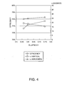
lens elements 200, a ratio obtained by dividing the second length w by the first length h is 1 to 4. Here, an angular field of view index will be explained with reference to Fig. 3. A vertical axis and a horizontal axis of Fig. 3 indicate an arbitrary luminance quantity and an angle with respect to a normal (0 degree in the front) of thescreen 100, respectively. A solid line indicates an angular field of view distribution in the horizontal direction and a broken line indicates an angular field of view in the vertical direction. A peak luminance of light traveling in a normal direction of the screen is set as a reference intensity. A maximum angle, at which light of half the reference intensity is irradiated, is set as an angular field of view index α. Similarly, a maximum angle, at which light of one third of the reference intensity is irradiated, is set as an angular field of view index β and a maximum angle, at which light of one tens of the reference intensity is irradiated, is set as an angular field of view index y. - An inverse of the ratio obtained by dividing the second length w by the first length h is defined as an ellipicity. Fig. 4 shows both the angular field of view α and light utilization efficiency at the time when a ratio of the first length h and the second length w is changed. According to an increase in the ratio in the vertical direction, an angular field of view in the vertical direction increases but the light utilization efficiency decreases. In this way, it is possible to adjust radiation characteristics (scattering degrees) in the vertical direction and the horizontal direction of video light according to the ratio of the vertical direction and the horizontal direction of the
lens elements 200, that is, the ellipicity. As described above, it is possible to keep a proper balance between an angular field of view in the vertical direction and an angular field of view in the horizontal direction by setting the ratio obtained by dividing the second length w by the first length h to 1 to 4. More preferably, as conditions of thescreen 100, it is desirable that utilization efficiency of the video light is 73% or more and the angular field of view in the vertical direction α is 12 degrees or more. - Next, a lens occupancy ratio and a screen characteristic will be explained. In a relation between a curvature radius R and a lens pitch of the
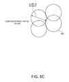
lenses 201, when the curvature radius R is changed, thelenses 201 overlap each other, and the entire surface of thelenses 201 are covered by a micro-lens array, a lens occupancy ratio is defined as 100%. In other words, in a state in which the lens occupancy ratio is 100%, there is no flat portion on thelens elements 200. With the curvature radius at this point as a reference, a lens occupancy ratio is defined according to a curvature radius ratio at the time when the curvature radius R is changed. - Figs. 5A, 5B, and 5C show examples of the curvature radius R and a lens diameter φ in the case of the
lens occupancy ratios 100%, 95%, and 97.5%, respectively. Both the curvature radius R and the lens diameter φ are indicated by a unit of micrometer. When the lens occupancy ratio is 100%, the curvature radius R of thelens elements 200 is 41.06 and the lens diameter φ thereof is 82.13. When the lens occupancy ratio is 95%, the curvature radius R of thelens elements 200 is 39.08 and the lens diameter φ thereof is 78.17. When the lens occupancy ratio is 97.5%, the curvature radius R of thelens elements 200 is 40.07 and the lens diameter φ thereof is 80.15. - Preferably, assuming that a curvature radius at the time when lens forming surfaces of the
lens elements 200 are entirely covered by curvature surfaces of thelenses 201 is 100%, it is desirable that a curvature radius ratio of thelenses 201 is 50 to 150%. Fig. 6 shows a relation between a lens occupancy and an angular field of view characteristic. As it is evident from Fig. 6, the angular field of view characteristic has a maximum near the lens occupancy ratio of 100%. It is desirable that the lens occupancy is 50 to 150% and, more preferably, 70 to 130%. Consequently, it is possible to obtain satisfactory values for both the angular field of view and the light utilization efficiency. Note that, in this embodiment, an external shape of thelens elements 200 is hexagonal as described above. If the lens occupancy ratio is changed, an amount of overlap of theadjacent lens elements 200 changes. Therefore, an external shape of lens elements can take various shapes such as circular, substantially octagonal, and rectangular according to the lens occupancy ratio. - Fig. 7 shows a sectional structure of a
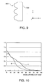
screen 700 according to a second embodiment of the invention.Flat portions 701 are formed to be substantially perpendicular to a z-axis direction, which is an optical axis, near vertexes of lens elements. Fig. 8 shows a relation between a size (i.e., an initial hole diameter indicated by a horizontal axis) of theflat portions 701 and an angular field of vision characteristic. It is desirable that the size of theflat portions 701 is about 1 to 20% and, more preferably, about 3 to 10% of a lens diameter of respective lens elements. Consequently, it is possible to increase scattered light in a front direction and improve a video quality in the front direction without significantly narrowing down an angular field of view. - As shown in Fig. 9, slopes 901 may be formed in peripheral parts of lenses of lens elements. As shown in Fig. 10, compared with the case in which the
slopes 901 are not provided as indicated by a curve D, a light utilization ratio is improved when theslopes 901 are provided as indicated by a curve C. Therefore, by forming theslopes 901 in peripheral parts of lens elements, it is possible to control video light to be condensed in a range of an angular field of view where frequency of presence of the observers OBS is high. - It is desirable to set a haze value of the lens elements is 0 to 90%. Fig. 11 shows a relation among a haze value, efficiency, and an angular field of view. The haze value is defined as 0% when incident light is transmitted directly and as 100% when incident light is scattered entirely. It is possible to control the haze value by roughening lens surfaces or mixing a scattering agent in the lens elements. Consequently, it is possible to uniformalize video light.
- The screen of the embodiment can be manufactured according to a manufacturing method described below. A mold of a desired shape is formed by machining, a mask is formed by a method of transferring the shape to a resin material, a sputtering method, an evaporation method, a CVD, or the like, a resist film is formed on a synthetic quartz substrate by a spin coat method or a spray coat method, and, then, a mask opening is formed by a photolithography technique. After the mask opening is provided, the substrate is immersed in a fluorine solution and the substrate is etched by isotropic etching from the mask opening to form a lens shape. A replica is formed using this glass substrate as a mold.
- As explained above, it is possible to irradiate a predetermined amount of light in necessary directions at high light utilization efficiency and obtain a bright and uniform video in a predetermined area by changing sizes in the vertical and horizontal direction of lens elements and a lens occupancy ratio and controlling radiation angles in the vertical and horizontal directions of a screen. In addition, a light-emitting diode may be used as a light source of a projector. Moreover, lens surfaces may be formed on an observer side of the screen.
- As described above, the screen according to the invention is suitable for projectors, and in particular to rear projectors including a transmission screen.
Claims (8)
- A screen comprising a lens array having plural spherical lens elements, wherein
a first length of the lens elements along a first direction passing substantially centers of the respective lens elements and a second length of the lens elements along a second direction passing substantially the centers of the respective lens elements and substantially orthogonal to the first direction are set such that the second length is larger than the first length, and
a curvature center position of any one of the plural lens elements is arranged to be at substantially a half of the first length along the first direction with respect to a curvature center position of another lens element adjacent to the lens element in the second direction. - A screen according to claim 1, wherein a ratio obtained by dividing the second length by the first length is 1 to 4.
- A screen according to claim 1 or 2, wherein, assuming that a curvature radius at the time when lens forming surfaces of lens elements are entirely covered by curvature surfaces of lenses is 100%, a curvature radius ratio of the lens elements is 50 to 150%.
- A screen according to claim 1, 2 or 3 wherein flat portions are formed near vertexes of the lens elements so as to be substantially vertical to an optical axis direction.
- A screen according to any one of the claims 1 to 4 wherein slopes are provided in peripheral parts of lenses of the lens elements.
- A screen according to any one of the claims 1 to 5 wherein a haze value of the lens elements is 0 to 90%.
- A screen according to any one of the claims 1 to 6 wherein the lens elements have substantially a hexagonal external appearance.
- A projector comprising:a light source that supplies light;a spatial light modulator that modulates light from the light source according to an image signal;a projection optical system that projects the modulated light; anda screen on which the projected light from the projection optical system is projected, whereinthe screen is a screen according to any one of the claims 1 to 7.
Applications Claiming Priority (1)
| Application Number | Priority Date | Filing Date | Title |
|---|---|---|---|
| JP2004207178A JP3900173B2 (en) | 2004-07-14 | 2004-07-14 | Screen and projector |
Publications (1)
| Publication Number | Publication Date |
|---|---|
| EP1617285A1 true EP1617285A1 (en) | 2006-01-18 |
Family
ID=35134258
Family Applications (1)
| Application Number | Title | Priority Date | Filing Date |
|---|---|---|---|
| EP05015103A Withdrawn EP1617285A1 (en) | 2004-07-14 | 2005-07-12 | Screen and projector |
Country Status (6)
| Country | Link |
|---|---|
| US (1) | US7382534B2 (en) |
| EP (1) | EP1617285A1 (en) |
| JP (1) | JP3900173B2 (en) |
| KR (1) | KR100729890B1 (en) |
| CN (1) | CN1721981A (en) |
| TW (1) | TWI272446B (en) |
Families Citing this family (5)
| Publication number | Priority date | Publication date | Assignee | Title |
|---|---|---|---|---|
| KR100876757B1 (en) | 2003-10-31 | 2009-01-07 | 삼성전자주식회사 | Subchannel Configuration System and Method in Communication System |
| JP2012230252A (en) * | 2011-04-26 | 2012-11-22 | Oki Data Corp | Lens array, lens unit, exposure device, image forming apparatus, and reader |
| JP6089616B2 (en) * | 2012-11-20 | 2017-03-08 | セイコーエプソン株式会社 | Light source device and projector |
| US10008822B2 (en) * | 2014-10-10 | 2018-06-26 | The Boeing Company | Laser system and method for controlling the wave front of a laser beam |
| JP2021117279A (en) * | 2020-01-23 | 2021-08-10 | セイコーエプソン株式会社 | Projection optics and projector |
Citations (6)
| Publication number | Priority date | Publication date | Assignee | Title |
|---|---|---|---|---|
| US4875064A (en) * | 1986-08-06 | 1989-10-17 | Casio Computer Co., Ltd. | Projector apparatus with mirror means |
| US4993806A (en) * | 1989-05-08 | 1991-02-19 | Dai Nippon Printing Co., Ltd. | Rear-projection screen |
| JPH03113434A (en) * | 1989-09-27 | 1991-05-14 | Dainippon Printing Co Ltd | Transmission type screen |
| US6317263B1 (en) * | 1999-06-18 | 2001-11-13 | 3M Innovative Properties Company | Projection screen using dispersing lens array for asymmetric viewing angle |
| US20020109915A1 (en) * | 2000-09-29 | 2002-08-15 | Hitachi, Ltd. | Rear projection display apparatus and translucent screen for use therein |
| EP1302787A2 (en) * | 2001-10-11 | 2003-04-16 | Nitto Denko Corporation | Optical sheet and display device having the optical sheet |
Family Cites Families (13)
| Publication number | Priority date | Publication date | Assignee | Title |
|---|---|---|---|---|
| JPS5662238A (en) | 1979-10-25 | 1981-05-28 | Asahi Glass Co Ltd | See-through type bright view screen |
| JPS57172435A (en) | 1981-04-16 | 1982-10-23 | Yamatake Honeywell Co Ltd | Keyboard for console |
| JPH0943588A (en) | 1995-07-28 | 1997-02-14 | Nippon Sheet Glass Co Ltd | Liquid crystal display device |
| JP2001305315A (en) | 2000-02-14 | 2001-10-31 | Fuji Photo Film Co Ltd | Light diffusing plate, liquid crystal display device and rear projector device |
| JP2002357869A (en) | 2001-06-01 | 2002-12-13 | Toppan Printing Co Ltd | Microlens sheet and rear projection screen and display device using the same |
| WO2002099530A1 (en) * | 2001-06-01 | 2002-12-12 | Toppan Printing Co., Ltd. | Micro-lens sheet and projection screen |
| JP3522716B2 (en) | 2001-07-13 | 2004-04-26 | 株式会社有沢製作所 | screen |
| JP2004029402A (en) | 2002-06-26 | 2004-01-29 | Toppan Printing Co Ltd | Microlens array sheet having a light shielding layer |
| US6848795B2 (en) * | 2002-10-24 | 2005-02-01 | Eastman Kodak Company | Increased contrast overhead projection films |
| JP4898121B2 (en) * | 2003-01-08 | 2012-03-14 | エクスプレイ エルティーディー | Image projection device |
| JP2004309733A (en) | 2003-04-04 | 2004-11-04 | Seiko Epson Corp | Manufacturing method of substrate with concave portion, substrate with concave portion, substrate with concave portion for microlens, microlens substrate, transmission screen and rear projector |
| JP2005017919A (en) | 2003-06-27 | 2005-01-20 | Toppan Printing Co Ltd | Transmission screen |
| JP4380522B2 (en) * | 2004-02-06 | 2009-12-09 | 日本ビクター株式会社 | Manufacturing method of replica mold for microlens array |
-
2004
- 2004-07-14 JP JP2004207178A patent/JP3900173B2/en not_active Expired - Fee Related
-
2005
- 2005-06-08 CN CNA2005100751177A patent/CN1721981A/en active Pending
- 2005-06-28 TW TW094121596A patent/TWI272446B/en not_active IP Right Cessation
- 2005-07-11 US US11/177,418 patent/US7382534B2/en not_active Expired - Fee Related
- 2005-07-12 EP EP05015103A patent/EP1617285A1/en not_active Withdrawn
- 2005-07-13 KR KR1020050063085A patent/KR100729890B1/en not_active Expired - Fee Related
Patent Citations (6)
| Publication number | Priority date | Publication date | Assignee | Title |
|---|---|---|---|---|
| US4875064A (en) * | 1986-08-06 | 1989-10-17 | Casio Computer Co., Ltd. | Projector apparatus with mirror means |
| US4993806A (en) * | 1989-05-08 | 1991-02-19 | Dai Nippon Printing Co., Ltd. | Rear-projection screen |
| JPH03113434A (en) * | 1989-09-27 | 1991-05-14 | Dainippon Printing Co Ltd | Transmission type screen |
| US6317263B1 (en) * | 1999-06-18 | 2001-11-13 | 3M Innovative Properties Company | Projection screen using dispersing lens array for asymmetric viewing angle |
| US20020109915A1 (en) * | 2000-09-29 | 2002-08-15 | Hitachi, Ltd. | Rear projection display apparatus and translucent screen for use therein |
| EP1302787A2 (en) * | 2001-10-11 | 2003-04-16 | Nitto Denko Corporation | Optical sheet and display device having the optical sheet |
Non-Patent Citations (1)
| Title |
|---|
| PATENT ABSTRACTS OF JAPAN vol. 015, no. 316 (P - 1237) 13 August 1991 (1991-08-13) * |
Also Published As
| Publication number | Publication date |
|---|---|
| KR100729890B1 (en) | 2007-06-18 |
| JP2006030454A (en) | 2006-02-02 |
| KR20060050116A (en) | 2006-05-19 |
| TWI272446B (en) | 2007-02-01 |
| CN1721981A (en) | 2006-01-18 |
| JP3900173B2 (en) | 2007-04-04 |
| US20060012877A1 (en) | 2006-01-19 |
| TW200602794A (en) | 2006-01-16 |
| US7382534B2 (en) | 2008-06-03 |
Similar Documents
| Publication | Publication Date | Title |
|---|---|---|
| EP1120682B1 (en) | Liquid crystal projector with polarization conversion element | |
| KR100917497B1 (en) | Screen and projection system | |
| US7931377B2 (en) | Screen and projection system | |
| US8228603B2 (en) | Screen and projector | |
| JP4407585B2 (en) | LIGHTING DEVICE, IMAGE DISPLAY DEVICE, AND PROJECTOR | |
| US20050078367A1 (en) | Screen and projector | |
| CN102124407A (en) | Projection system with imaging light source module | |
| JP4821204B2 (en) | LIGHTING DEVICE, IMAGE DISPLAY DEVICE, AND PROJECTOR | |
| US7538943B2 (en) | Screen and image display apparatus | |
| US20020113911A1 (en) | Liquid crystal display element and projection type liquid crystal display device | |
| US7382534B2 (en) | Screen and projector with spherical lens array | |
| CN100523941C (en) | Projector system | |
| US5839808A (en) | Projection optical system | |
| JP2005189470A (en) | Screen and projector | |
| JP2024092310A (en) | projector | |
| US8345190B2 (en) | Polarization optical system and projection-type liquid-crystal display device | |
| JP2007171561A (en) | Screen and rear projection display device | |
| JP2008158173A (en) | Screen and rear projector | |
| JP2024092309A (en) | projector | |
| JP2007206394A (en) | Lens sheet, screen and rear projector | |
| JP2007163832A (en) | Screen and rear projection display device | |
| JP2005283827A (en) | Spatial light modulator | |
| JP2005345905A (en) | Reflective liquid crystal spatial light modulator and image display device | |
| JP2005070633A (en) | Spatial light modulator and projector |
Legal Events
| Date | Code | Title | Description |
|---|---|---|---|
| PUAI | Public reference made under article 153(3) epc to a published international application that has entered the european phase |
Free format text: ORIGINAL CODE: 0009012 |
|
| AK | Designated contracting states |
Kind code of ref document: A1 Designated state(s): AT BE BG CH CY CZ DE DK EE ES FI FR GB GR HU IE IS IT LI LT LU LV MC NL PL PT RO SE SI SK TR |
|
| AX | Request for extension of the european patent |
Extension state: AL BA HR MK YU |
|
| 17P | Request for examination filed |
Effective date: 20060531 |
|
| 17Q | First examination report despatched |
Effective date: 20060707 |
|
| AKX | Designation fees paid |
Designated state(s): DE FR GB |
|
| GRAP | Despatch of communication of intention to grant a patent |
Free format text: ORIGINAL CODE: EPIDOSNIGR1 |
|
| STAA | Information on the status of an ep patent application or granted ep patent |
Free format text: STATUS: THE APPLICATION IS DEEMED TO BE WITHDRAWN |
|
| 18D | Application deemed to be withdrawn |
Effective date: 20100420 |