EP1616782A1 - Self-retracting lockable step-assembly for boats - Google Patents
Self-retracting lockable step-assembly for boats Download PDFInfo
- Publication number
- EP1616782A1 EP1616782A1 EP05076543A EP05076543A EP1616782A1 EP 1616782 A1 EP1616782 A1 EP 1616782A1 EP 05076543 A EP05076543 A EP 05076543A EP 05076543 A EP05076543 A EP 05076543A EP 1616782 A1 EP1616782 A1 EP 1616782A1
- Authority
- EP
- European Patent Office
- Prior art keywords
- ladder
- water
- telescoping
- self
- watercraft
- Prior art date
- Legal status (The legal status is an assumption and is not a legal conclusion. Google has not performed a legal analysis and makes no representation as to the accuracy of the status listed.)
- Granted
Links
- XLYOFNOQVPJJNP-UHFFFAOYSA-N water Substances O XLYOFNOQVPJJNP-UHFFFAOYSA-N 0.000 claims abstract description 61
- 230000009182 swimming Effects 0.000 claims abstract description 25
- 230000001960 triggered effect Effects 0.000 claims abstract description 14
- 230000008859 change Effects 0.000 claims abstract description 13
- 230000007246 mechanism Effects 0.000 abstract description 19
- 230000006835 compression Effects 0.000 description 3
- 238000007906 compression Methods 0.000 description 3
- 239000000463 material Substances 0.000 description 3
- 238000000034 method Methods 0.000 description 3
- 239000004033 plastic Substances 0.000 description 3
- 230000008569 process Effects 0.000 description 3
- 230000000712 assembly Effects 0.000 description 2
- 238000000429 assembly Methods 0.000 description 2
- 239000011152 fibreglass Substances 0.000 description 2
- 230000006872 improvement Effects 0.000 description 2
- 238000007689 inspection Methods 0.000 description 2
- 125000006850 spacer group Chemical group 0.000 description 2
- 229910000831 Steel Inorganic materials 0.000 description 1
- 230000009194 climbing Effects 0.000 description 1
- 238000010276 construction Methods 0.000 description 1
- 239000011796 hollow space material Substances 0.000 description 1
- 230000004048 modification Effects 0.000 description 1
- 238000012986 modification Methods 0.000 description 1
- 230000002035 prolonged effect Effects 0.000 description 1
- 230000003014 reinforcing effect Effects 0.000 description 1
- 239000010959 steel Substances 0.000 description 1
- 238000003466 welding Methods 0.000 description 1
Images




Classifications
-
- B—PERFORMING OPERATIONS; TRANSPORTING
- B63—SHIPS OR OTHER WATERBORNE VESSELS; RELATED EQUIPMENT
- B63B—SHIPS OR OTHER WATERBORNE VESSELS; EQUIPMENT FOR SHIPPING
- B63B27/00—Arrangement of ship-based loading or unloading equipment for cargo or passengers
- B63B27/14—Arrangement of ship-based loading or unloading equipment for cargo or passengers of ramps, gangways or outboard ladders ; Pilot lifts
- B63B27/146—Pilot ladders or similar outboard ladders, e.g. bathing ladders; Pilot lifts
-
- E—FIXED CONSTRUCTIONS
- E06—DOORS, WINDOWS, SHUTTERS, OR ROLLER BLINDS IN GENERAL; LADDERS
- E06C—LADDERS
- E06C5/00—Ladders characterised by being mounted on undercarriages or vehicles Securing ladders on vehicles
- E06C5/02—Ladders characterised by being mounted on undercarriages or vehicles Securing ladders on vehicles with rigid longitudinal members
- E06C5/04—Ladders characterised by being mounted on undercarriages or vehicles Securing ladders on vehicles with rigid longitudinal members capable of being elevated or extended ; Fastening means during transport, e.g. mechanical, hydraulic
-
- B—PERFORMING OPERATIONS; TRANSPORTING
- B63—SHIPS OR OTHER WATERBORNE VESSELS; RELATED EQUIPMENT
- B63B—SHIPS OR OTHER WATERBORNE VESSELS; EQUIPMENT FOR SHIPPING
- B63B27/00—Arrangement of ship-based loading or unloading equipment for cargo or passengers
- B63B27/14—Arrangement of ship-based loading or unloading equipment for cargo or passengers of ramps, gangways or outboard ladders ; Pilot lifts
- B63B2027/141—Arrangement of ship-based loading or unloading equipment for cargo or passengers of ramps, gangways or outboard ladders ; Pilot lifts telescopically extendable
Definitions
- the present invention is directed to a step assembly which is mounted to a swimming platform in the rear of a watercraft or boat, such as a pleasure boat, and which can be extended and locked when the watercraft or boat is essentially motionless to allow persons to descend into the water or ascend into the watercraft or boat, and which retracts when the watercraft or boat is in forward motion in the water.
- Patent No. 5,427,049 describes a self-retracting ladder assembly to be utilized in connection with personal watercraft. This ladder assembly is mounted underneath the riding platform of the personal watercraft and its surfaces are exposed to the thrust of the water generated by the jet pump. The ladder assembly of Patent No. 5,427,049 functions reasonably well when used on personal watercraft powered by a jet pump.
- step or ladder assemblies used on boats are described in United States Patent Nos. 5,152,244, 5,458,080 and 5,927,433.
- an improvement of the prior art is needed for boats where the rear of the hull includes a swimming platform.
- the self-retracting step assembly of the present invention provides such improvement.
- a self-retracting step assembly which is attached to a swimming platform provided on the rear of the hull of a boat.
- the self-retracting step assembly includes a ladder comprising a series of telescoping tubes which enable its extension and retraction.
- the step assembly including the ladder assembly are attached to the swimming platform in a position in which the ladder is capable of extending into the water wherein the watercraft or boat floats.
- the telescoping ladder assembly can be extended and placed from a normally horizontal position into an inclined position wherein at least the last step of the ladder reaches the water.
- the energy for extending the ladder is supplied by a human user or by a motor.
- the step assembly includes the motor or mechanical means for storing the energy used for extending the ladder.
- the ladder assembly is locked into the extended and inclined position by an improved mechanism that is located within the assembly attached to the swimming platform. Retraction of the ladder assembly is triggered by a change in the angle of the ladder relative to the water, said change being triggered by force of the water relative to the ladder when the watercraft or boat moves.
- the energy utilized for the retraction is preferably the stored energy of the extension, or it can be supplied by a motor.
- the novel step assembly of the present invention is mounted to the swimming platform 50 of boats 52 . It is well known in the art that many boats, primarily the boats used for pleasure, include such swimming platforms 50 onto which a person may step when he or she desires to enter the water 51 .
- the novel step assembly of the present invention is designed to be attached to the underside of the swimming platform 50 . Nevertheless, in modern boats wherein the hull includes a swimming platform 50 that has no horizontally disposed bottom surface the novel step assembly of the invention can be attached to the upper surface of the swimming platform 50 . This is shown in Figure 33 of the attached drawings.
- FIGS 1 through 16 disclose the first preferred embodiment of the novel step assembly of the present invention in detail.
- the step assembly includes a base plate 54 that is attached to cross-members 56 of the swimming platform 50 by a bolts and nuts assembly 58 .
- the step assembly also includes a cover 60 which is preferably made of fiberglass or plastic material.
- the cover 60 can be attached to side plates 62 of the step assembly by bolts and nuts, but in the preferred embodiment the bolt 64 that attaches the cover 60 to the side plates 62 includes a boss 66 into which the bolt 64 is fitted.
- the working mechanism of the self-retracting step assembly of the invention is contained in part within the box-like structure that is formed by the base plate 54 , side plates 62 and cover 60 .
- the working mechanism includes a ladder assembly that includes a pair of plurality of telescoping tubular members 68. Because of their telescoping nature the telescoping members 68 can be extended and retracted. Each pair of the telescoping members 68 is disposed substantially parallel with the respective side plates 62 of the step assembly so that when the telescoping members 68 are extended they form a U-shaped structure.
- Cross bars or rungs 70 are attached between the telescoping members 68 and a substantially flat, substantially rectangular member 72 is mounted to each cross bar or rung 70 .
- the substantially flat rectangular members 72 serve as steps when a person (not shown) utilizes the ladder assembly for entering or coming out of the water 51 and into the boat 52 .
- the tubular telescoping members 68 and the rungs 70 are made of steel and the rungs 70 are welded to the telescoping members 68 .
- the rectangular members 72 which serve as steps are preferably made of fiberglass or plastic material and are attached to the rungs 70 by screws or bolts (not shown).
- each pair of the telescoping members 68 has three tubes of successively smaller diameter, three rungs 70 interconnect the telescoping members 68 and one step 72 is mounted to each rung 70 .
- the first or largest of the tubular members 68 on each side of the step assembly is attached to a pivot block 74 shown in several of the drawing figures and perhaps best shown in Figures 8, 11, 12, and 13.
- Each pivot block 74 is attached to the respective side plate 62 of the step assembly on a hinge that is formed by a bolt 76 .
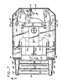
- the portion of the pivot block 74 that faces the interior of the step assembly is formed in a shape that cooperates with the mechanism or means that locks the ladder assembly in an extended and inclined position when the boat 52 is motionless in the water. The parts and operation of this mechanism or means are described below with primary reference to Figure 7 .
- a cross member or cross plate 78 is mounted between the side plates 62 .
- the cross plate 78 serves as a brace to reinforce the substantially box shaped structure formed by the base plate 54 and side plates 62 .
- a reel or spool 80 is mounted in the space between the base plate 54 and the reinforcing cross plate or brace 78 .
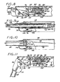
- the spool 80 and its mounting to the base plate 54 are best shown in Figures 8 and 11 . Proceeding in the description from the top of Figure 8 downward, first a round spacer 82 , preferably made of plastic materials is attached to the base plate 54 . One function of the round spacer 82 is to keep the spool 80 from wobbling.
- a boss 84 is attached, preferably by welding to the underside of the base plate 54 and the rotational axle 86 of the spool 80 is embedded in the boss 86 .
- the rotational axle 86 is in fact a shoulder bolt.
- a torsional spring 88 is disposed within a hollow space provided in the spool 80 and a flange 90 encloses the interior of the spool 80 .
- Below the flange 90 is the cross brace 78 , a washer 92 and a nut 94 that is placed on the shoulder bolt 86 whereby the spool 80 is solidly held and is nevertheless capable to rotate within the above described assembly.
- the circumference of the spool 80 includes a groove 96 in which a cable 98 rides. From the spool 80 the cable 98 is led through two pulleys 100 and a tensioner pulley 101 into the interior of each of the pair of telescoping tubular members 68. Each end of the cable 98 is attached to the respective end of the last telescoping member 68 that has the smallest diameter among the three telescoping members 68 .
- a pulley 102 is attached to a flange 104 provided in each of the first telescoping members 68 , namely the ones that have the largest diameter.
- the cable 98 is wrapped around the spool 80 and rides in its groove 96 and also rides over the two pulleys 100 , the tensioner pulley 101 and the pulleys 102 attached to the flanges 104 .
- Placement of the cable 98 within the interior of the tubular members 68 and attachment of the ends of the cable 98 to the last of the tubular members 68 is best shown in Figure 9 .
- the flanges 104 also serve to prevent the first of the tubular members 68 from being pulled out of the assembly, as is shown in Figure 10 .
- Each of the remaining tubular members 68 have a flange or flared end in their interior to prevent the members 68 from being pulled out from each other.
- each pulley 100 is mounted within a boss 106 welded to the base plate 54 on an axle formed by a bolt 108 and includes a retainer 110 which prevents the cable 98 from falling out of the groove of the respective pulley 100 .
- the herein described pulleys 100 and 101 are not self-adjusting to compensate for stretching of the cable 98 . Nevertheless the pulley 101 in the middle among the three in the herein described preferred embodiment can be adjusted to compensate for stretching of the cable 98 that may occur after prolonged use.
- this tensioner pulley 101 is mounted on a plate 112 that includes a slot 114 . When adjustment is needed the plate 112 is moved further on its mounting, as permitted by the slot 114 .
- a tensioner pulley 116 that is spring loaded and therefore self-adjusts for stretching of the cable 98 is shown in Figure 17 in connection with an alternative embodiment.
- the extended ladder assembly is rotated, still by the force of the human user (not shown), about the hinges or axles formed by the bolt 76 , into an inclined position.
- the inclined position at portion of the ladder assembly is in the water 51 .
- a person (not shown) can utilize the ladder assembly to enter into or exit from the water 51 .
- Two bosses 120 are mounted to the underside of the cross plate or brace 78 and a plate 122 carrying a bolt 124 is mounted on an axle 125 which is held by the two bosses 120 .
- the bolt 124 serves as a spool locking pin.
- the two bosses 120 and the axle 125 held by them is also shown in Figure 7.
- a rod 126 is attached to the plate 122 in a position which is transverse to the longitudinal axis of extension of the three tubular members 68 .
- the rod 126 is biased, that is being pulled towards the base plate 54 of the assembly by a tension spring 128 that is mounted both to the base plate 54 and to the rod 126 .
- the rear ends of the two pivot blocks 74 interface with the rod 126 .
- the rear ends of the pivot blocks push the plate 122 downward against the biasing force of the tension spring 128 .
- the spool locking pin or bolt 124 carried on the plate 122 is not in the locking channel 118 of the spool 80 , nor is the locking channel 118 in a position facing the spool locking pin 124 .
- Upward rotation of the extended and inclined telescoping members 68 can be initiated by human force. More importantly in accordance with the present invention it is automatically initiated when the boat 52 moves forward relative to the water 51 . This is because the portions of the ladder assembly in the water 51 act as a hydrofoil and result in a force that rotates upward the extended tubular members 68 .
- Figures 17 and 18 disclose another embodiment where the spool 80 has a recess 132 on its circumference and a spring-loaded arm 134 may engage the recess 132 and lock the inclined tubular members 68 into extended and inclined position.
- Figure 18 is a schematic representation of a bell crank 136 connected with a cable 138 to the spring-loaded arm 134 .
- Figure 19 schematically discloses still another embodiment for the locking mechanism, wherein a recess 138 is provided in one of the tubular members 68 and ball 140 is pushed under bias of a spring 142 into the recess 138 .
- the bias of the spring 142 is overcome by the pull of a cable 144 which is activated, for example, through a bell crank (not shown for this embodiment) interacting with the rear end of the block 74 when the tubular members 68 are not in the extended and inclined position.
- FIGs 20 and 21 schematically disclose still another embodiment wherein instead of the torsion springs 130 of the first preferred embodiment tension springs 146 are used to assist motion of the extended tubular members 68 from the inclined into the upright position.
- Figure 22 schematically discloses still another embodiment which includes the cable and spool assembly is for retracting the tubular members 68 and where any one of the previously described locking mechanism may be used optionally to lock the tubular members 68 into extended and inclined position.
- the retraction of the tubular members 68 is accomplished with an electric or hydraulic motor 148 which is connected to the spool 80 trough gears 150 .
- One or more swithches 152 may control the operation of the motor 148 in accordance with the position of the pivot blocks 74 .
- FIG. 23 , 24 and 25 disclose still another embodiment of the present invention where tensions springs 154 store the energy provided by a human user (not shown) when the user extends the tubular members 68 .
- This embodiment retains the cable 98 but has no spool. Locking of the tubular members 68 into extended and reclined position is accomplished by one or more cable locks 156 (shown schematically in Figure 24 ) which, as in the first preferred embodiment, are controlled by the position of the pivot blocks 74 .
- FIG. 26 discloses yet another embodiment.
- This embodiment is analogous to the embodiment shown by Figures 23 , 24 and 25 except that instead of the tension springs 154 compression springs 156 are used to store the energy of the human user (not shown) when the user extends the tubular members 68 .
- the compression springs 156 retract the tubular members 68 when they are no longer in the extended and inclined position.
- This embodiment also utilizes the pivot blocks 74 and may utilize cable locks 156 , or the locking mechanism described in connection with Figure 19 to lock the extended tubular members 68 into the inclined position.
- FIG. 27 discloses still another alternative embodiment that retains the cable 98 which interconnects the extended tubular members 68 with the retracting mechanism.
- the power to retract is provided by one or more hydraulically operated cylinders 158 .
- Switches (not shown) provided in appropriate locations in the assembly may control the operation of the hydraulic cylinders, or the cylinders can be operated manually.
- Figure 28 discloses still another embodiment of the present invention.
- a tension spring 160 stores the energy which is utilized by the human user (not shown) to extend the ladder assembly.
- the tension spring 160 also pulls the ladder assembly back into retracted position as described below.
- This embodiment similarly to the previously described embodiments, also has three telescoping tubular members.
- a dog 168 is attached on an axle 170 to the smallest tube 164 and the dog 168 cooperates with the camming surface 166 of the rod 162 .
- the tension spring 160 is attached to the dog 168 and as a result the tension spring 160 exerts a pulling force on the smallest tube 164 .
- the remaining two tubes 172 and 174 include apertures or holes 176 in their interior surfaces and pins 178 which also include a camming surface 180 .
- the pins 178 can enter into the respective holes 176 and in cooperation with the dog 168 keep the ladder assembly in a retracted and inclined position.
- Figure 29 shows the pivot blocks 74 which, similarly to the previously described embodiments, make it possible to bend the extended ladder assembly into the inclioned position where the last step 72 (schematically shown) is mounted on an axle 182 to allow some pivoting motion.
Landscapes
- Engineering & Computer Science (AREA)
- Mechanical Engineering (AREA)
- Chemical & Material Sciences (AREA)
- Combustion & Propulsion (AREA)
- Ocean & Marine Engineering (AREA)
- Ladders (AREA)
- Vehicle Step Arrangements And Article Storage (AREA)
- Lock And Its Accessories (AREA)
- Vehicle Body Suspensions (AREA)
Abstract
Description
- The present application claims the priority of U.S. provisional
application serial number 60/489,823, filed on July 23, 2003. - The present invention is directed to a step assembly which is mounted to a swimming platform in the rear of a watercraft or boat, such as a pleasure boat, and which can be extended and locked when the watercraft or boat is essentially motionless to allow persons to descend into the water or ascend into the watercraft or boat, and which retracts when the watercraft or boat is in forward motion in the water.
- Boats and ships are well known in the art. Many boats, primarily motor and sailboats used for pleasure include a swimming platform mounted to the rear of the hull. The swimming platform usually has a horizontal surface unto which a person can step prior to entering the water that floats the boat. Generally speaking, it is difficult for most persons to enter the water directly from the swimming platform and even more difficult, often virtually impossible, for the average person to ascend to the swimming platform from the water. For this reason the prior art provided ladders which can be lowered from the swimming platform into the water and which render it easier for a person to enter into and exit from the water. For several reasons it is usually considered undesirable to leave such ladders in the water when the boat is in motion, therefore the ladder is usually retracted before, or soon after, the boat begins moving. The prior art ladders utilized for this purpose, generally speaking, require extension and retraction by entirely manual operation. This involves manually folding the ladder downward when the ladder is placed into the water and the reverse manual operation when the ladder is retracted.
- United States Patent No. 5,427,049 describes a self-retracting ladder assembly to be utilized in connection with personal watercraft. This ladder assembly is mounted underneath the riding platform of the personal watercraft and its surfaces are exposed to the thrust of the water generated by the jet pump. The ladder assembly of Patent No. 5,427,049 functions reasonably well when used on personal watercraft powered by a jet pump.
- Other step or ladder assemblies used on boats are described in United States Patent Nos. 5,152,244, 5,458,080 and 5,927,433. In spite of the availability of these prior art step or ladder assemblies an improvement of the prior art is needed for boats where the rear of the hull includes a swimming platform. The self-retracting step assembly of the present invention provides such improvement.
- It is an object of the present invention to provide a self-retracting step assembly mounted to the swimming platform of a boat which can be used to facilitate getting into the water from the boat and climbing aboard the boat from the water.
- It is another object of the present invention to provide a step assembly which meets the following objective and which includes an improved mechanism to lock a ladder into an extended and inclined position wherein at least a last step of the ladder is in the water.
- It is still another object of the present invention to provide a step assembly which meets the foregoing objectives and wherein retraction of the ladder is automatically triggered by forward movement of the boat in the water.
- The foregoing and other objects and advantages are attained in accordance with the present invention by a self-retracting step assembly which is attached to a swimming platform provided on the rear of the hull of a boat. The self-retracting step assembly includes a ladder comprising a series of telescoping tubes which enable its extension and retraction. The step assembly including the ladder assembly are attached to the swimming platform in a position in which the ladder is capable of extending into the water wherein the watercraft or boat floats. The telescoping ladder assembly can be extended and placed from a normally horizontal position into an inclined position wherein at least the last step of the ladder reaches the water. The energy for extending the ladder is supplied by a human user or by a motor. The step assembly includes the motor or mechanical means for storing the energy used for extending the ladder. The ladder assembly is locked into the extended and inclined position by an improved mechanism that is located within the assembly attached to the swimming platform. Retraction of the ladder assembly is triggered by a change in the angle of the ladder relative to the water, said change being triggered by force of the water relative to the ladder when the watercraft or boat moves. The energy utilized for the retraction is preferably the stored energy of the extension, or it can be supplied by a motor.
- The features of the present invention can be best understood together with further objects and advantages by reference to the following description, taken in connection with the accompanying drawings, wherein like numerals indicate like parts.
-
- Figure 1 is a perspective view showing the self-retracting step assembly mounted to the swimming platform of a boat.
- Figure 2 is a cross-sectional view taken on
lines - Figure 3 is a plan view taken on
lines - Figure 4 is a plan view similar to the one taken on
lines - Figure 5 is a plan view taken on line 5,5 of Figure 2.
- Figure 6 is a plan view taken on
lines - Figure 7 is a view, partly in cross section, taken on
lines - Figure 8 is a view, partly in cross section, taken on lines 8,8 of Figure 7.
- Figure 9 is a view, partly in cross section, taken on lines 9,9 of Figure 7 showing the ladder assembly in the retracted position.
- Figure 10 is a view, partly in cross section, similar to the one taken on line 9,9 of Figure 7 and showing the ladder assembly in the extended position.
- Figure 11 is a view, partly in cross section, similar to the one taken on line 8,8 of Figure 7 and showing the ladder assembly in the extended and inclined position.
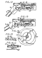
- Figure 12 is a view, partly in cross section, similar to the one taken on line 8,8 of Figure 7 and showing the ladder assembly moving up from the extended and inclined position.
- Figure 13 is a view, partly in cross section, similar to the one taken on line 8,8 of Figure 7 and showing the ladder assembly moving still further up from the extended and inclined position.
- Figure 14 is a view, partly in cross-section showing the cable spool of the first preferred embodiment in detail.
- Figure 15 is a cross-sectional view taken on
lines - Figure 16 is a cross-sectional view taken on
lines - Figure 17 is a view, partly in cross section, similar to the view of Figure 7 and showing another preferred embodiment of the invention.
- Figure 18 is a view, partly in cross section, taken on
lines - Figure 19 is a schematic view of the locking mechanism of still another preferred embodiment.
- Figures 20 and 21 are schematic views showing yet another preferred embodiment wherein a tension spring provides force to move the ladder assembly into a horizontal position.
- Figure 22 is a view, partly in cross section, showing a further embodiment of the invention that includes a motor for retracting the ladder assembly.
- Figure 23 is a schematic view of a still further embodiment showing an extension spring utilized for retracting the ladder assembly.
- Figure 24 is a schematic view of a still further embodiment wherein a cable clamp is utilized for locking the ladder assembly into the extended and inclined position.
- Figure 25 is a schematic view showing the same embodiment as Figure 23 with the ladder assembly extended.
- Figure 26 is a schematic view of still another further embodiment showing compression springs utilized for retracting the ladder assembly.
- Figure 27 is a schematic view showing hydraulically operated cylinders for retracting the ladder assembly.
- Figure 28 is a schematic bottom plan view of yet another embodiment of the present invention wherein springs are utilized instead of cables and pulley for retracting the ladder assembly of the present invention.
- Figure 29 is a view taken on
lines - Figure 30 is a view showing the locking mechanism to keep extended the ladder assembly of the embodiment of Figure 29.
- Figure 31 is a view showing the release of the locking mechanism of the embodiment of Figure 29.
- Figure 32 is a schematic view indicating the release of the locking mechanism by movement of the boat in the water.
- Figure 33 is a schematic view showing the self-retracting step assembly mounted above the swimming platform of a boat.
- The following specification taken in conjunction with the drawings sets forth the preferred embodiments of the present invention. The embodiments of the invention disclosed herein are the best modes contemplated by the inventors for carrying out their invention in a commercial environment, although it should be understood that various modifications can be accomplished within the parameters of the present invention.
- Referring now to the drawing figures the novel self-retracting step assembly of the present invention is disclosed. The novel step assembly of the present invention is mounted to the
swimming platform 50 of boats 52. It is well known in the art that many boats, primarily the boats used for pleasure, includesuch swimming platforms 50 onto which a person may step when he or she desires to enter thewater 51. The novel step assembly of the present invention is designed to be attached to the underside of theswimming platform 50. Nevertheless, in modern boats wherein the hull includes aswimming platform 50 that has no horizontally disposed bottom surface the novel step assembly of the invention can be attached to the upper surface of theswimming platform 50. This is shown in Figure 33 of the attached drawings. - Figures 1 through 16 disclose the first preferred embodiment of the novel step assembly of the present invention in detail. The step assembly includes a
base plate 54 that is attached tocross-members 56 of theswimming platform 50 by a bolts and nuts assembly 58. The step assembly also includes acover 60 which is preferably made of fiberglass or plastic material. Thecover 60 can be attached toside plates 62 of the step assembly by bolts and nuts, but in the preferred embodiment thebolt 64 that attaches thecover 60 to theside plates 62 includes aboss 66 into which thebolt 64 is fitted. - The working mechanism of the self-retracting step assembly of the invention is contained in part within the box-like structure that is formed by the
base plate 54,side plates 62 andcover 60. The working mechanism includes a ladder assembly that includes a pair of plurality of telescopingtubular members 68. Because of their telescoping nature thetelescoping members 68 can be extended and retracted. Each pair of thetelescoping members 68 is disposed substantially parallel with therespective side plates 62 of the step assembly so that when thetelescoping members 68 are extended they form a U-shaped structure. Cross bars orrungs 70 are attached between thetelescoping members 68 and a substantially flat, substantiallyrectangular member 72 is mounted to each cross bar orrung 70. The substantially flatrectangular members 72 serve as steps when a person (not shown) utilizes the ladder assembly for entering or coming out of thewater 51 and into the boat 52. In the herein described first preferred embodiment thetubular telescoping members 68 and therungs 70 are made of steel and therungs 70 are welded to thetelescoping members 68. Therectangular members 72 which serve as steps are preferably made of fiberglass or plastic material and are attached to therungs 70 by screws or bolts (not shown). In the preferred embodiments of the invention each pair of thetelescoping members 68 has three tubes of successively smaller diameter, threerungs 70 interconnect thetelescoping members 68 and onestep 72 is mounted to eachrung 70. - The first or largest of the
tubular members 68 on each side of the step assembly is attached to apivot block 74 shown in several of the drawing figures and perhaps best shown in Figures 8, 11, 12, and 13. Eachpivot block 74 is attached to therespective side plate 62 of the step assembly on a hinge that is formed by abolt 76. The portion of thepivot block 74 that faces the interior of the step assembly is formed in a shape that cooperates with the mechanism or means that locks the ladder assembly in an extended and inclined position when the boat 52 is motionless in the water. The parts and operation of this mechanism or means are described below with primary reference to Figure 7. - Referring now primarily to Figure 7 a cross member or cross
plate 78 is mounted between theside plates 62. Thecross plate 78 serves as a brace to reinforce the substantially box shaped structure formed by thebase plate 54 andside plates 62. A reel orspool 80 is mounted in the space between thebase plate 54 and the reinforcing cross plate orbrace 78. Thespool 80 and its mounting to thebase plate 54 are best shown in Figures 8 and 11. Proceeding in the description from the top of Figure 8 downward, first around spacer 82, preferably made of plastic materials is attached to thebase plate 54. One function of theround spacer 82 is to keep thespool 80 from wobbling. Aboss 84 is attached, preferably by welding to the underside of thebase plate 54 and therotational axle 86 of thespool 80 is embedded in theboss 86. Therotational axle 86 is in fact a shoulder bolt. A torsional spring 88 is disposed within a hollow space provided in thespool 80 and a flange 90 encloses the interior of thespool 80. Below the flange 90 is thecross brace 78, awasher 92 and anut 94 that is placed on theshoulder bolt 86 whereby thespool 80 is solidly held and is nevertheless capable to rotate within the above described assembly. - The circumference of the
spool 80 includes agroove 96 in which acable 98 rides. From thespool 80 thecable 98 is led through twopulleys 100 and a tensioner pulley 101 into the interior of each of the pair of telescopingtubular members 68. Each end of thecable 98 is attached to the respective end of thelast telescoping member 68 that has the smallest diameter among the threetelescoping members 68. Apulley 102 is attached to aflange 104 provided in each of thefirst telescoping members 68, namely the ones that have the largest diameter. Thus, thecable 98 is wrapped around thespool 80 and rides in itsgroove 96 and also rides over the twopulleys 100, the tensioner pulley 101 and thepulleys 102 attached to theflanges 104. Placement of thecable 98 within the interior of thetubular members 68 and attachment of the ends of thecable 98 to the last of thetubular members 68 is best shown in Figure 9. Theflanges 104 also serve to prevent the first of thetubular members 68 from being pulled out of the assembly, as is shown in Figure 10. Each of the remainingtubular members 68 have a flange or flared end in their interior to prevent themembers 68 from being pulled out from each other. - Detailed construction of the
pulleys 100 of the herein described preferred embodiment is disclosed by Figure 16. Eachpulley 100 is mounted within aboss 106 welded to thebase plate 54 on an axle formed by a bolt 108 and includes a retainer 110 which prevents thecable 98 from falling out of the groove of therespective pulley 100. The herein describedpulleys 100 and 101 are not self-adjusting to compensate for stretching of thecable 98. Nevertheless the pulley 101 in the middle among the three in the herein described preferred embodiment can be adjusted to compensate for stretching of thecable 98 that may occur after prolonged use. As it is shown in Figure 7, this tensioner pulley 101 is mounted on aplate 112 that includes aslot 114. When adjustment is needed theplate 112 is moved further on its mounting, as permitted by theslot 114. Atensioner pulley 116 that is spring loaded and therefore self-adjusts for stretching of thecable 98 is shown in Figure 17 in connection with an alternative embodiment. - It should be already apparent from the foregoing description and inspection of the drawing figures that a user (not shown) can manually extend the three
tubular members 68 of the ladder assembly by pulling the last member with a force that overcomes the force of the torsional spring 88 within thespool 80. By virtue of thecable 98 being disposed in thegroove 96 of thecable 98 thespool 80 rotates while thetubular members 68 are pulled out. In this process the torsion spring 88 is wound and, as a result, stores the energy expanded by the user (not shown) who extends thetubular members 68. After thetubular members 68 have been pulled out in a horizontal or substantially horizontal direction the extended ladder assembly is rotated, still by the force of the human user (not shown), about the hinges or axles formed by thebolt 76, into an inclined position. In the inclined position at portion of the ladder assembly is in thewater 51. In this inclined position of the ladder assembly a person (not shown) can utilize the ladder assembly to enter into or exit from thewater 51. - In the prior art extendible and self-retracting ladder and step assembly of United States patent No. 5,427,049 there are camming surfaces which more or less correspond to the position of the pivot blocks 74 of this invention, and these camming surfaces tend to lock the extended ladder of that disclosure in an inclined position, until motion of the watercraft or boat tilts the ladder upward and the ladder is retracted by the force of a spring. The step assembly of this invention comprises a significantly improved locking mechanism which is best shown for the first preferred embodiment in Figures 8 and 11 -15. Thus, the underside of the
spool 80 includes a ramped recess that serves as lockingchannel 118. Twobosses 120 are mounted to the underside of the cross plate or brace 78 and aplate 122 carrying abolt 124 is mounted on anaxle 125 which is held by the twobosses 120. Thebolt 124 serves as a spool locking pin. The twobosses 120 and theaxle 125 held by them is also shown in Figure 7. By virtue of being mounted on theaxle 125 theplate 122 is capable of some pivoting movement. Arod 126 is attached to theplate 122 in a position which is transverse to the longitudinal axis of extension of the threetubular members 68. Therod 126 is biased, that is being pulled towards thebase plate 54 of the assembly by atension spring 128 that is mounted both to thebase plate 54 and to therod 126. - For operation of the locking mechanism the rear ends of the two pivot blocks 74 interface with the
rod 126. In the retracted position of thetubular members 68 shown in Figure 8 the rear ends of the pivot blocks push theplate 122 downward against the biasing force of thetension spring 128. In this position of thetubular members 68 the spool locking pin or bolt 124 carried on theplate 122 is not in the lockingchannel 118 of thespool 80, nor is the lockingchannel 118 in a position facing thespool locking pin 124. - When the
tubular members 68 are fully, or substantially fully, extended then, due to the rotation of thespool 80, the recess forming the lockingchannel 118 in the underside of thespool 80 occupies a position facing thespool locking pin 124. The ramp and stop shape of the locking channel 118 (shown in Figure 15) allows for multiple rotation of thespool 80 before thepin 124 is locked in thechannel 118. When the extendedtubular members 68 are rotated downward to occupy an inclined position then the rear ends of the pivot blocks 74 disengage therod 126 of theplate 122 and the biasing force of thetension spring 128 pulls thespool locking pin 124 into the lockingchannel 118. This is shown in Figure 11. In this inclined position of thetubular members 68, thetubular members 68 are locked into the extended and inclined position. This is the position in which the ladder assembly is used by persons wishing to go into thewater 51 or ascend to theswimming platform 50 of the boat 52. - It should be apparent to those skilled in the art in light of the foregoing description and the drawing figures that rotation of the extended
tubular members 68 about theaxles 76 reverses the above described process, as is shown in Figures 12 and 13. During this reverse process the rear ends of the pivot blocks 74 come into contact with therod 126 and push theplate 122 downward and thereby pull the spool locking pin 108 out of thespool locking channel 118. Torsion springs 130 mounted within the pivot blocks 74 on theaxles 76 engage thecross brace 78 and the interior of theblocks 74. These provide a force tending to place thetubular members 68 into the upward position wherein they are retracted by thecable 98 which is wound up on thespool 80 under the force of the torsional spring 88 inside thespool 80. - Upward rotation of the extended and
inclined telescoping members 68 can be initiated by human force. More importantly in accordance with the present invention it is automatically initiated when the boat 52 moves forward relative to thewater 51. This is because the portions of the ladder assembly in thewater 51 act as a hydrofoil and result in a force that rotates upward the extendedtubular members 68. - Whereas the foregoing description in connection with Figures 1 through 16 discloses the presently preferred embodiment, and particularly the presently preferred locking mechanism of the invention, other locking mechanisms still utilizing the cable and spool arrangement can be incorporated in the present invention. For example, Figures 17 and 18 disclose another embodiment where the
spool 80 has arecess 132 on its circumference and a spring-loadedarm 134 may engage therecess 132 and lock the inclinedtubular members 68 into extended and inclined position. Figure 18 is a schematic representation of a bell crank 136 connected with acable 138 to the spring-loadedarm 134. When the rear end of the block 74 (shown only schematically in Figure 18) is in contact with the bell crank 136 then the spring-loadedarm 134 is not in therecess 132 nor is therecess 132 in position to accept the spring-loadedarm 134. Figure 17 shows this embodiment in the position where the spring-loadedarm 134 is about to engage or about to disengage therecess 132. However, when the rear end of theblock 74 no longer pushes against the bell crank 136 then the spring loadedarm 134 engages therecess 132 and locks the ladder assembly. - Figure 19 schematically discloses still another embodiment for the locking mechanism, wherein a
recess 138 is provided in one of thetubular members 68 andball 140 is pushed under bias of aspring 142 into therecess 138. The bias of thespring 142 is overcome by the pull of acable 144 which is activated, for example, through a bell crank (not shown for this embodiment) interacting with the rear end of theblock 74 when thetubular members 68 are not in the extended and inclined position. - Figures 20 and 21 schematically disclose still another embodiment wherein instead of the torsion springs 130 of the first preferred embodiment tension springs 146 are used to assist motion of the extended
tubular members 68 from the inclined into the upright position. - Figure 22 schematically discloses still another embodiment which includes the cable and spool assembly is for retracting the
tubular members 68 and where any one of the previously described locking mechanism may be used optionally to lock thetubular members 68 into extended and inclined position. However, the retraction of thetubular members 68 is accomplished with an electric orhydraulic motor 148 which is connected to thespool 80 trough gears 150. One or more swithches 152, only one of which is shown, may control the operation of themotor 148 in accordance with the position of the pivot blocks 74. - The schematic views of Figures 23, 24 and 25 disclose still another embodiment of the present invention where tensions springs 154 store the energy provided by a human user (not shown) when the user extends the
tubular members 68. This embodiment retains thecable 98 but has no spool. Locking of thetubular members 68 into extended and reclined position is accomplished by one or more cable locks 156 (shown schematically in Figure 24) which, as in the first preferred embodiment, are controlled by the position of the pivot blocks 74. - The schematic view of Figure 26 discloses yet another embodiment. This embodiment is analogous to the embodiment shown by Figures 23, 24 and 25 except that instead of the tension springs 154 compression springs 156 are used to store the energy of the human user (not shown) when the user extends the
tubular members 68. The compression springs 156 retract thetubular members 68 when they are no longer in the extended and inclined position. This embodiment also utilizes the pivot blocks 74 and may utilizecable locks 156, or the locking mechanism described in connection with Figure 19 to lock the extendedtubular members 68 into the inclined position. - The schematic view of Figure 27 discloses still another alternative embodiment that retains the
cable 98 which interconnects the extendedtubular members 68 with the retracting mechanism. In this embodiment the power to retract is provided by one or more hydraulically operatedcylinders 158. Switches (not shown) provided in appropriate locations in the assembly may control the operation of the hydraulic cylinders, or the cylinders can be operated manually. - Figure 28 discloses still another embodiment of the present invention. In this embodiment there is no cable and no spool. A
tension spring 160 stores the energy which is utilized by the human user (not shown) to extend the ladder assembly. Thetension spring 160 also pulls the ladder assembly back into retracted position as described below. This embodiment, similarly to the previously described embodiments, also has three telescoping tubular members. There is arod 162 in thetube 164 of the smallest diameter and therod 162 ends in acamming surface 166. Adog 168 is attached on anaxle 170 to thesmallest tube 164 and thedog 168 cooperates with thecamming surface 166 of therod 162. Thetension spring 160 is attached to thedog 168 and as a result thetension spring 160 exerts a pulling force on thesmallest tube 164. - The remaining two
tubes 172 and 174 include apertures or holes 176 in their interior surfaces and pins 178 which also include a camming surface 180. Thepins 178 can enter into therespective holes 176 and in cooperation with thedog 168 keep the ladder assembly in a retracted and inclined position. Figure 29 shows the pivot blocks 74 which, similarly to the previously described embodiments, make it possible to bend the extended ladder assembly into the inclioned position where the last step 72 (schematically shown) is mounted on anaxle 182 to allow some pivoting motion. - It should be readily apparent from the foregoing description and inspection of the drawing figures that when forward motion of the boat 52 creates a tilting force on the
step 72 that acts as a hydrofoil, thencam 166 is pushed inward, moves thedog 168 out of thehole 176 and thetension spring 160 retracts thetube 164 of the smallest diameter. The inwardly movingdog 168 then engages the camming surfaces 180 of therespective pins 178 of the twotubes 172 and 174 and removes thepins 178 from therespective holes 176 in thetubes 172 and 174 whereby the entire ladder assembly is retracted. - Still further variations of constructing a step assembly in accordance with the present invention may become readily apparent to those skilled in the art in accordance with the present disclosure. Therefore the scope of the present invention should be determined solely from the following claims, as such claims are interpreted in light of the disclosure and the relevant law and prior art.
Claims (20)
- A telescoping self-retracting step assembly for watercraft or boat, comprising:a ladder comprising a plurality of telescoping members enabling extension and retraction of the ladder, the ladder being attached to a watercraft or boat, the ladder including a surface that can act as a hydrofoil in the water;means for allowing rotation of the plurality of telescoping members when they are extended into a position where the surface capable of acting as the hydrofoil reaches the water;means for allowing extension of the ladder by energy supplied by a user for that purpose, said means including a cable attached to at least one of the telescoping tubes and a spool on which the cable is wound;spring means in operative engagement with the cable and spool for storing the energy used for extending the ladder;means for temporarily locking the ladder in the extended position wherein the surface that can act as a hydrofoil is in the water, andthe spring means being adapted for retracting the ladder by using the stored energy, said retraction being triggered by a change in the angle of the ladder relative to the water, said change being triggered by force of the water on the surface that acts as a hydrofoil when the watercraft or boat moves forward relative to the water, whereby the extended ladder self-retracts when the watercraft or boat moves.
- The self-retracting step assembly of Claim 1 further comprising means for attaching the step-assembly to a swimming platform affixed to a boat.
- The self-retracting step assembly of Claim 2 wherein the means for attaching are adapted for attaching the step assembly to an underside of the swimming platform.
- The self-retracting step assembly of Claim 1 wherein the means for temporarily locking the ladder in the extended position wherein the surface that can act as a hydrofoil is in the water includes a camming surface which is in operative engagement with the spring means, said camming surface acting as means for keeping the ladder in the extended position until the retraction is triggered by a change in the angle of the ladder relative to the water.
- The self-retracting step assembly of Claim 1 wherein the spring means comprise a torsion spring mounted to the spool.
- The self-retracting step assembly of Claim 5 wherein the spring means further comprise a torsion spring mounted to the means for allowing rotation.
- The self-retracting step assembly of Claim 1 wherein the means for temporarily locking includes a recess in the spool and a pin positioned in the the recess and acting as means for preventing rotation of the spool.
- The self retracting step-assembly of Claim 1 wherein the surface capable of acting as a hydrofoil comprises a step attached to one of the telescoping members.
- A telescoping self-retracting step assembly for watercraft or boat, comprising:a ladder comprising a plurality of telescoping members enabling extension and retraction of the ladder, the ladder being attached to a watercraft or boat, the ladder including a surface that can act as a hydrofoil in the water;means for allowing rotation of the plurality of telescoping members when they are extended into a position where the surface capable of acting as the hydrofoil reaches the water, said means including a plurality of pivot blocks;means for allowing extension of the ladder by energy supplied by a user for that purpose, said means including a cable attached to at least one of the telescoping tubes and a spool on which the cable is wound;spring means in operative engagement with the cable and spool for storing the energy used for extending the ladder;means for temporarily locking the ladder in the extended position wherein the surface that can act as a hydrofoil is in the water, said means for temporarily locking the ladder in the extended position including a camming surface which is in operative engagement with the spring means, the spool including a recess and the means for temporarily locking the ladder including a pin positioned in the recess, andthe spring means being adapted for retracting the ladder by using the stored energy, said retraction being triggered by a change in the angle of the ladder relative to the water, said change being triggered by force of the water on the surface that acts as a hydrofoil when the watercraft or boat moves forward relative to the water, whereby the extended ladder self-retracts when the watercraft or boat moves.
- The telescoping self-retracting step assembly of Claim 9 wherein the spring means comprise a torsion spring attached to the spool, and wherein the recess is located on the underside of the spool.
- The telescoping self-retracting step assembly of Claim 10 wherein the spring means further comprise a torsion spring acting on the pivot blocks.
- A telescoping self-retracting step assembly for watercraft or boat, comprising:a ladder comprising a plurality of telescoping members enabling extension and retraction of the ladder, the ladder being attached to a watercraft or boat, the ladder including a surface that can act as a hydrofoil in the water;means for allowing rotation of the plurality of telescoping members when they are extended into a position where the surface capable of acting as the hydrofoil reaches the water, said means including a plurality of pivot blocks;means for allowing extension of the ladder by energy supplied by a user for that purpose, said means including a cable attached to at least one of the telescoping tubes and a spool on which the cable is wound;spring means in operative engagement with the cable and spool for storing the energy used for extending the ladder;means for temporarily locking the ladder in the extended position wherein the surface that can act as a hydrofoil is in the water, said means for temporarily locking the ladder in the extended position including a camming surface which is in operative engagement with the spring means, the spool including a recess incorporated on the underside of the spool and the means for temporarily locking the ladder including a pin positioned in the recess, andthe spring means comprising a torsion spring attached to the spool and another spring acting on the pivot block the spring means being adapted for retracting the ladder by using the stored energy, said retraction being triggered by a change in the angle of the ladder relative to the water, said change being triggered by force of the water on the surface that acts as a hydrofoil when the watercraft or boat moves forward relative to the water, whereby the extended ladder self-retracts when the watercraft or boat moves.
- The telescoping self-retracting step assembly of Claim 12 further including a plurality of pulleys in engagement with the cable, said pulleys guiding the cable to the spool and to the telescoping tubes.
- The telescoping self-retracting step assembly of Claim 13 wherein said plurality of pulleys include a tensioner pulley forming means for adjusting tension of the cable.
- A telescoping step assembly for watercraft or boat, comprising:a ladder comprising a plurality of telescoping members enabling extension and retraction of the ladder, the ladder being attached to a watercraft or boat, the ladder including a surface that can act as a hydrofoil in the water;means for allowing rotation of the plurality of telescoping members when they are extended into a position where the surface capable of acting as the hydrofoil reaches the water;means for allowing extension of the ladder by energy supplied by a user for that purpose, said means including a cable attached to at least one of the telescoping tubes and a spool on which the cable is wound;means for temporarily locking the ladder in the extended position wherein the surface that can act as a hydrofoil is in the water, andmotor means being in operative engagement with the cable and spool for retracting the ladder when the watercraft or boat moves forward relative to the water, whereby the extended ladder retracts when the watercraft or boat moves.
- The telescoping step assembly of Claim 15 wherein the motor means are electrically operated.
- The telescoping step assembly of Claim 15 wherein the motor means are hydraulically operated.
- A telescoping self-retracting step assembly for watercraft or boat, comprising:a base plate;a ladder comprising a plurality of telescoping members enabling extension and retraction of the ladder, the ladder being attached to a watercraft or boat, the ladder including a surface that can act as a hydrofoil in the water;means for allowing the rotation of the plurality of telescoping members when they are extended into a position where the surface capable of acting as the hydrofoil reaches the water;means for allowing extension of the ladder by energy supplied by a user for that purpose, said means including a cable attached to at least one of the telescoping tubes;spring means in operative engagement with the cable storing the energy used for extending the ladder, said spring means being affixed to the base plate;means for temporarily locking the ladder in the extended position wherein the surface that can act as a hydrofoil is in the water, said locking means including a plurality of interfacing camming surfaces, pins and holes in the telescoping members, andthe spring means being adapted for retracting the ladder by using the stored energy, said retraction being triggered by a change in the angle of the ladder relative to the water, said change being triggered by force of the water on the surface that acts as a hydrofoil when the watercraft or boat moves forward relative to the water, whereby the extended ladder self-retracts when the watercraft or boat moves.
- The self-retracting step assembly of Claim 18 wherein the means for allowing rotation include a plurality of pivot blocks.
- The self retracting step assembly of Claim 18 where the spring means further comprise a substantially U-shaped tubes and a tension spring, the tension spring being held the U-shaped tube and the U-shaped tube being attached to the base plate.
Applications Claiming Priority (1)
| Application Number | Priority Date | Filing Date | Title |
|---|---|---|---|
| US10/892,713 US6904863B2 (en) | 2003-07-23 | 2004-07-16 | Self-retracting lockable step-assembly for boats |
Publications (2)
| Publication Number | Publication Date |
|---|---|
| EP1616782A1 true EP1616782A1 (en) | 2006-01-18 |
| EP1616782B1 EP1616782B1 (en) | 2008-01-02 |
Family
ID=35094392
Family Applications (1)
| Application Number | Title | Priority Date | Filing Date |
|---|---|---|---|
| EP05076543A Expired - Lifetime EP1616782B1 (en) | 2004-07-16 | 2005-07-06 | Self-retracting lockable step-assembly for boats |
Country Status (4)
| Country | Link |
|---|---|
| US (1) | US6904863B2 (en) |
| EP (1) | EP1616782B1 (en) |
| AT (1) | ATE382540T1 (en) |
| DE (1) | DE602005004075D1 (en) |
Cited By (5)
| Publication number | Priority date | Publication date | Assignee | Title |
|---|---|---|---|---|
| WO2009116920A1 (en) * | 2008-03-17 | 2009-09-24 | Stroemberg Bertil | Bathing and rescue ladder |
| ITVI20090239A1 (en) * | 2009-09-30 | 2011-04-01 | Besenzoni S P A | SIDE SERVICE PORT FOR BOATS |
| WO2011085504A1 (en) | 2010-01-13 | 2011-07-21 | Mueller Peter A | Light-weight platform having stairs |
| FR2963313A1 (en) * | 2010-07-27 | 2012-02-03 | Gilbert Rodriguez | Rigid nautical ladder device for use with e.g. boat, has ladder with discontinuous lateral uprights and median central upright, where kinematics of ladder support allows translation of ladder floated with immersed bars |
| US8671869B2 (en) | 2007-11-12 | 2014-03-18 | Peter A. Müller | Segmented platform |
Families Citing this family (44)
| Publication number | Priority date | Publication date | Assignee | Title |
|---|---|---|---|---|
| US7182175B1 (en) * | 2004-08-16 | 2007-02-27 | G.G. Schmitt & Sons, Inc. | Retractable telescopic boat ladder |
| US7237503B2 (en) * | 2004-12-28 | 2007-07-03 | Stagecoach Adventures, Inc. | Protective platform for a boat |
| US20060272895A1 (en) * | 2005-06-01 | 2006-12-07 | Jeffrey Lavoie | Detachable stairway system for water vehicles and method of use |
| ITMI20051028A1 (en) * | 2005-06-01 | 2006-12-02 | Douglas Marine Srl | RETRACTABLE LIFTING SYSTEM WITH RETRACTABLE LADDER FOR BOARDING BOATS |
| JP3117326U (en) * | 2005-10-03 | 2006-01-05 | 有限会社マリン・ワークス | Rescue ladder for floating pier |
| US8944210B2 (en) * | 2006-05-23 | 2015-02-03 | Vallery Industries, Inc. | Center ladder member apparatus and method |
| US20070281559A1 (en) * | 2006-05-30 | 2007-12-06 | Joseph Stanley | Amphibious recreational vessel |
| US7967110B2 (en) * | 2006-07-27 | 2011-06-28 | Werner Co. | Tubular access ladder and method |
| US9863187B2 (en) * | 2006-07-27 | 2018-01-09 | Werner Co. | Tubular access ladder and method |
| US20090199758A1 (en) * | 2008-02-11 | 2009-08-13 | Garelick Richard J | Stowable boat ladder |
| US20100012433A1 (en) * | 2008-07-18 | 2010-01-21 | Challenger Hardware Company | Self-locking extendable ladder for use with a boat |
| US20100229781A1 (en) * | 2009-03-13 | 2010-09-16 | Garelick Richard J | Slidably attached boat ladder |
| DE202009007991U1 (en) * | 2009-06-05 | 2010-10-28 | Ovibell Pflanzen, Deko Und Freizeit Gmbh & Co. Kg | Telescopic ladder |
| US8056496B1 (en) * | 2010-01-25 | 2011-11-15 | Patti Bussa | Floating deck apparatus for a pontoon boat |
| US20110277676A1 (en) * | 2010-05-17 | 2011-11-17 | Water Edward C Van De | Watercraft Stern Platform Extension Assembly |
| US8375880B1 (en) * | 2010-06-24 | 2013-02-19 | Cobalt Boats, LLC | Retractable step for boat swim platform |
| CN102001420B (en) * | 2010-11-19 | 2013-04-24 | 哈尔滨工程大学 | Three-point winding-rope telescopic accommodation ladder |
| US9580147B2 (en) | 2011-09-16 | 2017-02-28 | Malibu Boats, Llc | Surf wake system for a watercraft |
| DE102012214089A1 (en) * | 2012-08-08 | 2014-02-13 | Siemens Aktiengesellschaft | Vehicle with telescopic ladder |
| US9067647B2 (en) * | 2013-03-14 | 2015-06-30 | Grady-White Boats, Inc. | Portable boat ladder |
| US10427761B2 (en) | 2014-04-14 | 2019-10-01 | Premier Marine, Inc. | Retractable marine boarding ladder |
| WO2016120798A1 (en) * | 2015-01-28 | 2016-08-04 | Douglas Marine S.R.L. | Climbing system with telescopic ramp or ladder, in particular for boats or the like |
| USD759840S1 (en) | 2015-05-14 | 2016-06-21 | Premier Marine, Inc. | Retractable ladder |
| US10399645B1 (en) * | 2015-09-10 | 2019-09-03 | Brunswick Corporation | Manual submersible auxiliary swim platform for vessels |
| US9937979B1 (en) * | 2015-09-10 | 2018-04-10 | Brunswick Corporation | Manual submersible auxiliary swim platform for vessels |
| US9914508B2 (en) * | 2015-10-16 | 2018-03-13 | Grady-White Boats, Inc. | Stowable folding boat step |
| US20170145746A1 (en) * | 2015-11-19 | 2017-05-25 | Caterpillar Inc. | Ladders and methods for assembling ladders |
| US20170274828A1 (en) * | 2016-03-23 | 2017-09-28 | Ford Global Technologies, Llc | Running board assembly having multiple step pads |
| US10858887B2 (en) | 2016-08-11 | 2020-12-08 | Bobo Ladders Llc | Boat or recreational vehicle ladder apparatus |
| CN107444572B (en) * | 2017-06-23 | 2023-09-15 | 杭州华鹰游艇有限公司 | Concealed swimming ladder device |
| GR1009703B (en) * | 2018-10-08 | 2020-02-06 | Technohull Ανωνυμη Εταιρεια Κατασκευης Και Εμποριας Σκαφων Αναψυχης Και Ναυτιλιακων Ειδων | Automatic yacht's electric bathing ladder with mechanical energy storage accesssories |
| US11370508B1 (en) | 2019-04-05 | 2022-06-28 | Malibu Boats, Llc | Control system for water sports boat with foil displacement system |
| CN110576876B (en) * | 2019-10-11 | 2024-07-19 | 中车长春轨道客车股份有限公司 | Railway carriage boarding ladder |
| US11932356B1 (en) | 2020-08-24 | 2024-03-19 | Malibu Boats, Llc | Powered swim platform |
| USD995397S1 (en) | 2021-06-17 | 2023-08-15 | Brunswick Corporation | Swim platform assembly for boats |
| US12172732B1 (en) | 2021-06-17 | 2024-12-24 | Brunswick Corporation | Swim platform assemblies for boats |
| US11485456B1 (en) * | 2021-10-02 | 2022-11-01 | Paul J Casey | Table easily attachable to powered boats |
| US12595026B1 (en) | 2022-04-28 | 2026-04-07 | Brunswick Corporation | Patio dive doors for marine vessels having a swim step assembly |
| US12559035B2 (en) * | 2022-06-30 | 2026-02-24 | Nissan North America, Inc. | Ladder assemblies for vehicles |
| US12606274B1 (en) | 2022-10-11 | 2026-04-21 | Brunswick Corporation | Swim platform assemblies for boats |
| US11952837B1 (en) * | 2022-11-09 | 2024-04-09 | T-H Marine Supplies, Llc | Collapsible ladder |
| US11673629B1 (en) | 2022-11-21 | 2023-06-13 | White Water Marine Hardware, Inc. | Water vessel boarding ladder device and method of manufacture |
| US20240227986A1 (en) * | 2023-01-05 | 2024-07-11 | Leisure Properties Llc | Boarding platform |
| WO2025018985A1 (en) * | 2023-07-18 | 2025-01-23 | Tanann Llc | Compact electric outboard with retractable platform |
Citations (9)
| Publication number | Priority date | Publication date | Assignee | Title |
|---|---|---|---|---|
| US4682560A (en) * | 1985-07-08 | 1987-07-28 | Outboard Marine Corporation | High force release and reset mechanism for supporting a structure from a boat hull |
| DE4200176A1 (en) * | 1991-01-10 | 1992-07-16 | Amos Vignali | Double drum winch sensing device - has one drum detachable from common driving shaft and held stationary |
| FR2674212A1 (en) * | 1991-03-22 | 1992-09-25 | Roume Christian | Gangway for boat comprising a means serving as a shock absorber to avoid the gangway chafing on the quay |
| US5152244A (en) | 1991-12-16 | 1992-10-06 | Jarmillo Jr Alfonso | Self-positioning stirrup for a jet water craft |
| US5427049A (en) | 1994-06-17 | 1995-06-27 | Mardikian 1991 Irrevocable Trust | Self-retracting step assembly for personal watercraft |
| US5458080A (en) | 1994-03-11 | 1995-10-17 | Jaramillo, Sr.; Alfonso | Automatically retractable steps for watercraft |
| JPH08200000A (en) * | 1995-01-20 | 1996-08-06 | Furukawa Co Ltd | Horizontal reel device |
| US5927433A (en) | 1997-10-31 | 1999-07-27 | Jaramillo, Sr.; Alfonso | Boat step with improved support and retraction mechanism |
| US6021733A (en) * | 1999-01-07 | 2000-02-08 | Jaramillo, Sr.; Alfonso | Automatically retractable telescopic and rotatable steps for watercraft |
Family Cites Families (6)
| Publication number | Priority date | Publication date | Assignee | Title |
|---|---|---|---|---|
| US3532067A (en) * | 1968-09-18 | 1970-10-06 | Bonnie Vold Baker | Water-conveyance apparatus |
| US4926965A (en) * | 1989-10-18 | 1990-05-22 | Mark Fox | Self-retracting step |
| US4993341A (en) * | 1990-01-24 | 1991-02-19 | Merkel Don C | Controllable gangplank for pontoon boat |
| US5085165A (en) * | 1990-04-06 | 1992-02-04 | Reed William P | Gangplank for a pontoon boat |
| US5632591A (en) * | 1994-06-13 | 1997-05-27 | Henriquez; Kenneth R. | Ladder storage and transport device |
| US6125491A (en) * | 1998-09-21 | 2000-10-03 | United Dominion Industries, Inc. | Counterbalance for mechanical dock leveler |
-
2004
- 2004-07-16 US US10/892,713 patent/US6904863B2/en not_active Expired - Lifetime
-
2005
- 2005-07-06 AT AT05076543T patent/ATE382540T1/en not_active IP Right Cessation
- 2005-07-06 DE DE602005004075T patent/DE602005004075D1/en not_active Expired - Lifetime
- 2005-07-06 EP EP05076543A patent/EP1616782B1/en not_active Expired - Lifetime
Patent Citations (9)
| Publication number | Priority date | Publication date | Assignee | Title |
|---|---|---|---|---|
| US4682560A (en) * | 1985-07-08 | 1987-07-28 | Outboard Marine Corporation | High force release and reset mechanism for supporting a structure from a boat hull |
| DE4200176A1 (en) * | 1991-01-10 | 1992-07-16 | Amos Vignali | Double drum winch sensing device - has one drum detachable from common driving shaft and held stationary |
| FR2674212A1 (en) * | 1991-03-22 | 1992-09-25 | Roume Christian | Gangway for boat comprising a means serving as a shock absorber to avoid the gangway chafing on the quay |
| US5152244A (en) | 1991-12-16 | 1992-10-06 | Jarmillo Jr Alfonso | Self-positioning stirrup for a jet water craft |
| US5458080A (en) | 1994-03-11 | 1995-10-17 | Jaramillo, Sr.; Alfonso | Automatically retractable steps for watercraft |
| US5427049A (en) | 1994-06-17 | 1995-06-27 | Mardikian 1991 Irrevocable Trust | Self-retracting step assembly for personal watercraft |
| JPH08200000A (en) * | 1995-01-20 | 1996-08-06 | Furukawa Co Ltd | Horizontal reel device |
| US5927433A (en) | 1997-10-31 | 1999-07-27 | Jaramillo, Sr.; Alfonso | Boat step with improved support and retraction mechanism |
| US6021733A (en) * | 1999-01-07 | 2000-02-08 | Jaramillo, Sr.; Alfonso | Automatically retractable telescopic and rotatable steps for watercraft |
Non-Patent Citations (1)
| Title |
|---|
| PATENT ABSTRACTS OF JAPAN vol. 1996, no. 12 26 December 1996 (1996-12-26) * |
Cited By (6)
| Publication number | Priority date | Publication date | Assignee | Title |
|---|---|---|---|---|
| US8671869B2 (en) | 2007-11-12 | 2014-03-18 | Peter A. Müller | Segmented platform |
| WO2009116920A1 (en) * | 2008-03-17 | 2009-09-24 | Stroemberg Bertil | Bathing and rescue ladder |
| ITVI20090239A1 (en) * | 2009-09-30 | 2011-04-01 | Besenzoni S P A | SIDE SERVICE PORT FOR BOATS |
| EP2305553A1 (en) * | 2009-09-30 | 2011-04-06 | Besenzoni S.p.A. | Side service door for boats |
| WO2011085504A1 (en) | 2010-01-13 | 2011-07-21 | Mueller Peter A | Light-weight platform having stairs |
| FR2963313A1 (en) * | 2010-07-27 | 2012-02-03 | Gilbert Rodriguez | Rigid nautical ladder device for use with e.g. boat, has ladder with discontinuous lateral uprights and median central upright, where kinematics of ladder support allows translation of ladder floated with immersed bars |
Also Published As
| Publication number | Publication date |
|---|---|
| US20050016439A1 (en) | 2005-01-27 |
| EP1616782B1 (en) | 2008-01-02 |
| DE602005004075D1 (en) | 2008-02-14 |
| US6904863B2 (en) | 2005-06-14 |
| ATE382540T1 (en) | 2008-01-15 |
Similar Documents
| Publication | Publication Date | Title |
|---|---|---|
| EP1616782B1 (en) | Self-retracting lockable step-assembly for boats | |
| US7182175B1 (en) | Retractable telescopic boat ladder | |
| US9139258B2 (en) | Pullout shade system for boats | |
| US3774720A (en) | Power-operated retractable ladder for pleasure boats | |
| US20210084889A1 (en) | Tree stands, ladders, and associated systems and methods | |
| US11548595B2 (en) | Extendable ladder for watercraft | |
| US8297484B2 (en) | Height adjustable tower and cargo rack apparatus for wakeboard boats | |
| US6845845B2 (en) | Water recreation dock | |
| EP2888159B1 (en) | Platform steps | |
| US20030173152A1 (en) | Submerged water activity platform | |
| WO2011079401A2 (en) | Taffrail, which can be lowered, for a water vehicle | |
| US8936498B1 (en) | Telescoping trolling motor | |
| US8157054B1 (en) | Aquatic ladder for marine applications | |
| US7410031B2 (en) | Boat trailer bow entry ladder assembly | |
| US7228582B1 (en) | Extendable ramp for boats and vehicles | |
| US20080202852A1 (en) | Stowable boat ladder | |
| US20240083548A1 (en) | Adjustable height upper deck system and method | |
| US7314019B1 (en) | Retractable step with secure locking mechanism | |
| US20220240497A1 (en) | Extendable hunting stand with movable platform | |
| US7464792B2 (en) | Aquatic ladder adapted for marine applications | |
| US20230358098A1 (en) | Automatically Retractable Marine Ladder | |
| US12030459B2 (en) | Boat trailer stair system | |
| US7090049B2 (en) | Aquatic ladder adapted for marine applications | |
| US11952837B1 (en) | Collapsible ladder | |
| CA2151439C (en) | Personal water craft with rear mounting means |
Legal Events
| Date | Code | Title | Description |
|---|---|---|---|
| PUAI | Public reference made under article 153(3) epc to a published international application that has entered the european phase |
Free format text: ORIGINAL CODE: 0009012 |
|
| 17P | Request for examination filed |
Effective date: 20050706 |
|
| AK | Designated contracting states |
Kind code of ref document: A1 Designated state(s): AT BE BG CH CY CZ DE DK EE ES FI FR GB GR HU IE IS IT LI LT LU LV MC NL PL PT RO SE SI SK TR |
|
| AX | Request for extension of the european patent |
Extension state: AL BA HR MK YU |
|
| AKX | Designation fees paid |
Designated state(s): AT BE BG CH CY CZ DE DK EE ES FI FR GB GR HU IE IS IT LI LT LU LV MC NL PL PT RO SE SI SK TR |
|
| GRAP | Despatch of communication of intention to grant a patent |
Free format text: ORIGINAL CODE: EPIDOSNIGR1 |
|
| GRAS | Grant fee paid |
Free format text: ORIGINAL CODE: EPIDOSNIGR3 |
|
| GRAA | (expected) grant |
Free format text: ORIGINAL CODE: 0009210 |
|
| AK | Designated contracting states |
Kind code of ref document: B1 Designated state(s): AT BE BG CH CY CZ DE DK EE ES FI FR GB GR HU IE IS IT LI LT LU LV MC NL PL PT RO SE SI SK TR |
|
| REG | Reference to a national code |
Ref country code: GB Ref legal event code: FG4D |
|
| REG | Reference to a national code |
Ref country code: IE Ref legal event code: FG4D |
|
| REG | Reference to a national code |
Ref country code: CH Ref legal event code: EP |
|
| REF | Corresponds to: |
Ref document number: 602005004075 Country of ref document: DE Date of ref document: 20080214 Kind code of ref document: P |
|
| PG25 | Lapsed in a contracting state [announced via postgrant information from national office to epo] |
Ref country code: SI Free format text: LAPSE BECAUSE OF FAILURE TO SUBMIT A TRANSLATION OF THE DESCRIPTION OR TO PAY THE FEE WITHIN THE PRESCRIBED TIME-LIMIT Effective date: 20080102 Ref country code: NL Free format text: LAPSE BECAUSE OF FAILURE TO SUBMIT A TRANSLATION OF THE DESCRIPTION OR TO PAY THE FEE WITHIN THE PRESCRIBED TIME-LIMIT Effective date: 20080102 |
|
| NLV1 | Nl: lapsed or annulled due to failure to fulfill the requirements of art. 29p and 29m of the patents act | ||
| PG25 | Lapsed in a contracting state [announced via postgrant information from national office to epo] |
Ref country code: LI Free format text: LAPSE BECAUSE OF FAILURE TO SUBMIT A TRANSLATION OF THE DESCRIPTION OR TO PAY THE FEE WITHIN THE PRESCRIBED TIME-LIMIT Effective date: 20080102 Ref country code: LT Free format text: LAPSE BECAUSE OF FAILURE TO SUBMIT A TRANSLATION OF THE DESCRIPTION OR TO PAY THE FEE WITHIN THE PRESCRIBED TIME-LIMIT Effective date: 20080102 Ref country code: CH Free format text: LAPSE BECAUSE OF FAILURE TO SUBMIT A TRANSLATION OF THE DESCRIPTION OR TO PAY THE FEE WITHIN THE PRESCRIBED TIME-LIMIT Effective date: 20080102 Ref country code: ES Free format text: LAPSE BECAUSE OF FAILURE TO SUBMIT A TRANSLATION OF THE DESCRIPTION OR TO PAY THE FEE WITHIN THE PRESCRIBED TIME-LIMIT Effective date: 20080413 Ref country code: IS Free format text: LAPSE BECAUSE OF FAILURE TO SUBMIT A TRANSLATION OF THE DESCRIPTION OR TO PAY THE FEE WITHIN THE PRESCRIBED TIME-LIMIT Effective date: 20080502 Ref country code: FI Free format text: LAPSE BECAUSE OF FAILURE TO SUBMIT A TRANSLATION OF THE DESCRIPTION OR TO PAY THE FEE WITHIN THE PRESCRIBED TIME-LIMIT Effective date: 20080102 |
|
| REG | Reference to a national code |
Ref country code: CH Ref legal event code: PL |
|
| PG25 | Lapsed in a contracting state [announced via postgrant information from national office to epo] |
Ref country code: BG Free format text: LAPSE BECAUSE OF FAILURE TO SUBMIT A TRANSLATION OF THE DESCRIPTION OR TO PAY THE FEE WITHIN THE PRESCRIBED TIME-LIMIT Effective date: 20080402 Ref country code: AT Free format text: LAPSE BECAUSE OF FAILURE TO SUBMIT A TRANSLATION OF THE DESCRIPTION OR TO PAY THE FEE WITHIN THE PRESCRIBED TIME-LIMIT Effective date: 20080102 |
|
| PG25 | Lapsed in a contracting state [announced via postgrant information from national office to epo] |
Ref country code: BE Free format text: LAPSE BECAUSE OF FAILURE TO SUBMIT A TRANSLATION OF THE DESCRIPTION OR TO PAY THE FEE WITHIN THE PRESCRIBED TIME-LIMIT Effective date: 20080102 Ref country code: LV Free format text: LAPSE BECAUSE OF FAILURE TO SUBMIT A TRANSLATION OF THE DESCRIPTION OR TO PAY THE FEE WITHIN THE PRESCRIBED TIME-LIMIT Effective date: 20080102 Ref country code: PT Free format text: LAPSE BECAUSE OF FAILURE TO SUBMIT A TRANSLATION OF THE DESCRIPTION OR TO PAY THE FEE WITHIN THE PRESCRIBED TIME-LIMIT Effective date: 20080602 Ref country code: PL Free format text: LAPSE BECAUSE OF FAILURE TO SUBMIT A TRANSLATION OF THE DESCRIPTION OR TO PAY THE FEE WITHIN THE PRESCRIBED TIME-LIMIT Effective date: 20080102 |
|
| EN | Fr: translation not filed | ||
| PG25 | Lapsed in a contracting state [announced via postgrant information from national office to epo] |
Ref country code: DK Free format text: LAPSE BECAUSE OF FAILURE TO SUBMIT A TRANSLATION OF THE DESCRIPTION OR TO PAY THE FEE WITHIN THE PRESCRIBED TIME-LIMIT Effective date: 20080102 Ref country code: CZ Free format text: LAPSE BECAUSE OF FAILURE TO SUBMIT A TRANSLATION OF THE DESCRIPTION OR TO PAY THE FEE WITHIN THE PRESCRIBED TIME-LIMIT Effective date: 20080102 Ref country code: SK Free format text: LAPSE BECAUSE OF FAILURE TO SUBMIT A TRANSLATION OF THE DESCRIPTION OR TO PAY THE FEE WITHIN THE PRESCRIBED TIME-LIMIT Effective date: 20080102 Ref country code: SE Free format text: LAPSE BECAUSE OF FAILURE TO SUBMIT A TRANSLATION OF THE DESCRIPTION OR TO PAY THE FEE WITHIN THE PRESCRIBED TIME-LIMIT Effective date: 20080402 |
|
| PLBE | No opposition filed within time limit |
Free format text: ORIGINAL CODE: 0009261 |
|
| STAA | Information on the status of an ep patent application or granted ep patent |
Free format text: STATUS: NO OPPOSITION FILED WITHIN TIME LIMIT |
|
| PG25 | Lapsed in a contracting state [announced via postgrant information from national office to epo] |
Ref country code: RO Free format text: LAPSE BECAUSE OF FAILURE TO SUBMIT A TRANSLATION OF THE DESCRIPTION OR TO PAY THE FEE WITHIN THE PRESCRIBED TIME-LIMIT Effective date: 20080102 |
|
| 26N | No opposition filed |
Effective date: 20081003 |
|
| PG25 | Lapsed in a contracting state [announced via postgrant information from national office to epo] |
Ref country code: DE Free format text: LAPSE BECAUSE OF FAILURE TO SUBMIT A TRANSLATION OF THE DESCRIPTION OR TO PAY THE FEE WITHIN THE PRESCRIBED TIME-LIMIT Effective date: 20080403 |
|
| PG25 | Lapsed in a contracting state [announced via postgrant information from national office to epo] |
Ref country code: MC Free format text: LAPSE BECAUSE OF NON-PAYMENT OF DUE FEES Effective date: 20080731 |
|
| PG25 | Lapsed in a contracting state [announced via postgrant information from national office to epo] |
Ref country code: EE Free format text: LAPSE BECAUSE OF FAILURE TO SUBMIT A TRANSLATION OF THE DESCRIPTION OR TO PAY THE FEE WITHIN THE PRESCRIBED TIME-LIMIT Effective date: 20080102 Ref country code: FR Free format text: LAPSE BECAUSE OF FAILURE TO SUBMIT A TRANSLATION OF THE DESCRIPTION OR TO PAY THE FEE WITHIN THE PRESCRIBED TIME-LIMIT Effective date: 20081024 |
|
| PG25 | Lapsed in a contracting state [announced via postgrant information from national office to epo] |
Ref country code: IE Free format text: LAPSE BECAUSE OF NON-PAYMENT OF DUE FEES Effective date: 20080707 Ref country code: CY Free format text: LAPSE BECAUSE OF FAILURE TO SUBMIT A TRANSLATION OF THE DESCRIPTION OR TO PAY THE FEE WITHIN THE PRESCRIBED TIME-LIMIT Effective date: 20080102 |
|
| GBPC | Gb: european patent ceased through non-payment of renewal fee |
Effective date: 20090706 |
|
| PG25 | Lapsed in a contracting state [announced via postgrant information from national office to epo] |
Ref country code: GB Free format text: LAPSE BECAUSE OF NON-PAYMENT OF DUE FEES Effective date: 20090706 |
|
| PG25 | Lapsed in a contracting state [announced via postgrant information from national office to epo] |
Ref country code: HU Free format text: LAPSE BECAUSE OF FAILURE TO SUBMIT A TRANSLATION OF THE DESCRIPTION OR TO PAY THE FEE WITHIN THE PRESCRIBED TIME-LIMIT Effective date: 20080703 Ref country code: LU Free format text: LAPSE BECAUSE OF NON-PAYMENT OF DUE FEES Effective date: 20080706 |
|
| PG25 | Lapsed in a contracting state [announced via postgrant information from national office to epo] |
Ref country code: TR Free format text: LAPSE BECAUSE OF FAILURE TO SUBMIT A TRANSLATION OF THE DESCRIPTION OR TO PAY THE FEE WITHIN THE PRESCRIBED TIME-LIMIT Effective date: 20080102 |
|
| PG25 | Lapsed in a contracting state [announced via postgrant information from national office to epo] |
Ref country code: GR Free format text: LAPSE BECAUSE OF FAILURE TO SUBMIT A TRANSLATION OF THE DESCRIPTION OR TO PAY THE FEE WITHIN THE PRESCRIBED TIME-LIMIT Effective date: 20080403 |
|
| PGFP | Annual fee paid to national office [announced via postgrant information from national office to epo] |
Ref country code: IT Payment date: 20080731 Year of fee payment: 4 |