EP1616758A1 - Vehicle occupant protection apparatus and initiation method to use for vehicle occupant protection apparatus - Google Patents
Vehicle occupant protection apparatus and initiation method to use for vehicle occupant protection apparatus Download PDFInfo
- Publication number
- EP1616758A1 EP1616758A1 EP05013367A EP05013367A EP1616758A1 EP 1616758 A1 EP1616758 A1 EP 1616758A1 EP 05013367 A EP05013367 A EP 05013367A EP 05013367 A EP05013367 A EP 05013367A EP 1616758 A1 EP1616758 A1 EP 1616758A1
- Authority
- EP
- European Patent Office
- Prior art keywords
- acceleration
- vehicle
- integral
- initiation
- acceleration sensor
- Prior art date
- Legal status (The legal status is an assumption and is not a legal conclusion. Google has not performed a legal analysis and makes no representation as to the accuracy of the status listed.)
- Granted
Links
Images


Classifications
-
- B—PERFORMING OPERATIONS; TRANSPORTING
- B60—VEHICLES IN GENERAL
- B60R—VEHICLES, VEHICLE FITTINGS, OR VEHICLE PARTS, NOT OTHERWISE PROVIDED FOR
- B60R21/00—Arrangements or fittings on vehicles for protecting or preventing injuries to occupants or pedestrians in case of accidents or other traffic risks
- B60R21/01—Electrical circuits for triggering passive safety arrangements, e.g. airbags, safety belt tighteners, in case of vehicle accidents or impending vehicle accidents
- B60R21/013—Electrical circuits for triggering passive safety arrangements, e.g. airbags, safety belt tighteners, in case of vehicle accidents or impending vehicle accidents including means for detecting collisions, impending collisions or roll-over
- B60R21/0132—Electrical circuits for triggering passive safety arrangements, e.g. airbags, safety belt tighteners, in case of vehicle accidents or impending vehicle accidents including means for detecting collisions, impending collisions or roll-over responsive to vehicle motion parameters, e.g. to vehicle longitudinal or transversal deceleration or speed value
- B60R21/0133—Electrical circuits for triggering passive safety arrangements, e.g. airbags, safety belt tighteners, in case of vehicle accidents or impending vehicle accidents including means for detecting collisions, impending collisions or roll-over responsive to vehicle motion parameters, e.g. to vehicle longitudinal or transversal deceleration or speed value by integrating the amplitude of the input signal
Definitions
- the present invention relates to a vehicle occupant protection apparatus for protecting a vehicle occupant by controlling an operation of an occupant protection device (e.g. an airbag apparatus) according to a type of collision while a vehicle is colliding, and an initiation method to use for the vehicle occupant protection apparatus.
- an occupant protection device e.g. an airbag apparatus
- each of two inflators is not driven when the collision velocity is notably small, and only a first inflator is driven to half unfold an airbag (to inflate an airbag with a low pressure) when the collision velocity is medium, and further, after the first inflator is driven a second inflator is driven to fully unfold the airbag (to inflate the airbag with a high pressure) when the collision velocity is great.
- a vehicle occupant protection apparatus which detects deceleration with a single acceleration sensor, then calculates a first integrated value which is a time integrated value of the deceleration, then calculates a second integrated value by taking the time-integral of the first integrated value, then adds a weight value to each of the first integrated value and the second integrated value, and then drives an airbag by estimating movement of a vehicle occupant using the calculated sum (for reference, see Japanese Patent Publication No. H08-25430)
- a vehicle occupant protection apparatus detects acceleration with a single acceleration sensor thereof, then calculates acceleration, greatness of the acceleration, change in acceleration with time and a reduced quantity of velocity with a control circuit thereof, then estimates a scale of an impact by using those calculated values, and then drives each inflator according to the estimated scale (for reference, see Japanese Patent Laid-Open No. 2004-131084).
- an initiation control apparatus for use on a vehicle occupant protection apparatus detects deceleration of a vehicle with a single acceleration sensor thereof, then calculates a integral velocity value, which is a time integrated value of the deceleration, then detects when the integral velocity value exceeds a first predetermined threshold value and initiates a first inflator, and then initiates a second inflator at the time the integral velocity exceeds a second predetermined threshold value, so that the second inflator can be driven without fault in the case the time integrated value of the deceleration delays in responding after the first inflator is driven in an offset collision, by improving arithmetic calculation process (for reference, see Japanese Patent Laid-Open No. H11-263188).
- a type of the collision needs to be determined until 30 milliseconds (0.03 seconds) before the impact of the collision which may damage the occupant applies to the occupant to inflate the airbag according to the type of the collision.
- the first and second threshold values are predetermined in order to drive the first inflator when a low velocity head-on collision occurred and to drive the first and second inflator when a high velocity head-on collision occurred, then there may rise a case where the integrated value of the acceleration exceeds the first threshold value but does not exceed the second threshold value when a high velocity oblique collision or a high velocity offset collision occurs, and in such a case the second inflator may not be driven.
- Fig. 5 is a graph showing the problem described above.
- the lateral axis designates elapsed time from the beginning of a collision occurs, and the vertical axis designates integrated values of acceleration (time integrated values from the time collision occurs) detected with an acceleration sensor.
- the acceleration sensor may be attached either to an anterior-end portion of a vehicle or to a substantially central portion of the vehicle.
- “th1" designates a threshold value for initiating the first inflator
- th2 designates a threshold value for initiating the second inflator.
- the symbol “a” designates a characteristic of change in the integrated value in the case where a head-on collision occurs at a low velocity (e.g. 26 kilometer/hour).
- the symbol “b” designates a characteristic of change in the integrated value in the case where a head-on collision occurs at a high velocity (e.g. 35 kilometer/hour).
- the symbol “c” designates a characteristic of change in the integrated value in the case where an onset/oblique collision occurs at a high velocity (e.g. an offset collision at 64 kilometer/hour or an oblique collision at 40 kilometer/hour).
- an onset/oblique collision occurs at a high velocity
- an offset collision at 64 kilometer/hour or an oblique collision at 40 kilometer/hour As indicated with the symbol "c”, in a high velocity offset collision or a high velocity oblique collision there might occur the case where the integrated value of the acceleration exceeds the first threshold value th1 but does not exceed the second threshold value th2, and in such a case the second inflator may not be driven.
- an object of the present invention is to provide a vehicle occupant protection apparatus and an initiation method to use for the vehicle occupant protection apparatus capable of more properly initiating a vehicle occupant protection device according to a collision type by determining the collision type when a vehicle collides.
- a vehicle occupant protection apparatus comprisises: a first acceleration sensor, attached to a front portion of a vehicle, for detecting acceleration in the vehicle's longitudinal direction; a second acceleration sensor, attached to a substantially central portion in the vehicle's longitudinal direction, for detecting acceleration in the vehicle's longitudinal direction; an integral initiation control device for issuing an integral initiation command at the time acceleration detected by the first acceleration sensor exceeds a preset threshold value for determining whether a collision of the vehicle is occurring; a first acceleration integral device for obtaining a first integral acceleration value by taking the time integral of acceleration detected by the first acceleration sensor based on the integral initiation command from the integral initiation control device; a second acceleration integral device for obtaining a second integral acceleration value by taking the time integral of acceleration detected by the second acceleration sensor based on the integral initiation command from the integral initiation control device; a subtraction device for calculating a difference between the first integral acceleration value and the second integral acceleration value; and an initiation determining device for determining a type of the collision
- Fig. 1 is a block diagram showing a vehicle occupant protection apparatus of the first embodiment according to the present invention.
- the vehicle occupant protection apparatus 1 includes a first acceleration sensor (front acceleration sensor) 2, a second acceleration sensor (central acceleration sensor) 3, an airbag unfolding determining structure 4 as an initiation determining structure, an airbag unfolding driving device 5 as a driving device, and an airbag apparatus 6 as a vehicle occupant protection device.
- a first acceleration sensor front acceleration sensor
- second acceleration sensor central acceleration sensor
- an airbag unfolding determining structure 4 as an initiation determining structure
- an airbag unfolding driving device 5 as a driving device
- an airbag apparatus 6 as a vehicle occupant protection device.
- the first acceleration sensor 2 is attached to a substantially center of a front portion (nearby a radiator grille, for example) of a vehicle.
- the first acceleration sensor 2 detects acceleration of the vehicle in a longitudinal direction (vehicle's longitudinal acceleration) and outputs a detected acceleration output signal.
- the second acceleration sensor 3 is attached to a substantially center of the vehicle both in a longitudinal direction and in a lateral direction (e.g. a floor tunnel portion or a floor face close to a shift lever in the vehicle).
- This second acceleration sensor 3 does not need be located in an exact center of the vehicle in the longitudinal direction, and may be located in a portion closer to the center in the vehicle's longitudinal direction than a portion to which the first acceleration sensor 2 is attached.
- the second acceleration sensor 3 is attached to a portion located in a vehicle occupant area (i.e. an inside, an upside or a lower part of a vehicle occupant room).
- the first acceleration sensor 2 and the second acceleration sensor 3 output a positive (+) value for indicating acceleration tending to slow down the vehicle (i.e. deceleration) and a negative (-) value for indicating acceleration tending to speed up the vehicle in the case where output voltage is set to zero (0) while no acceleration is applied thereto.
- the airbag unfolding determining structure 4 is provided with LPFs (law-pass filter) 11, 12, A/D converters 13, 14, an integral initiation control device 15, a first acceleration integral device 16, a second acceleration integral device 17, a subtraction device 18, a first initiation determining device 21, a first initiation threshold value producing device 22, a second initiation determining device 23, and a second initiation threshold value producing device 24.
- LPFs law-pass filter
- the first and second initiation determining devices 21, 23 and the first and second initiation threshold value producing devices 22, 24 constitute an initiation determining device 20 as set forth in the claims.
- a high-frequency noise component is removed and a low-frequency component in response to a vehicle collision is abstracted from the detected acceleration output signal from the first acceleration sensor 2, and then the abstracted low-frequency component is provided for the A/D converter 13 to be converted into a digital signal.
- a high pass filter (not shown) may be employed in a previous step of the LPF 11, so that an influence of drift current of output voltage from the first acceleration sensor 2 can be excluded.
- a front acceleration digital signal (front acceleration data) outputted from the A/D converter 13 is provided for the integral initiation control device 15 and the first acceleration integral device 16.
- the integral initiation control device 15 continuously monitors the front acceleration (acceleration of the anterior portion of the vehicle) based on the front acceleration digital signal (front acceleration data), and issues an integral initiation command 15a at the time the front acceleration exceeds a preset collision determining threshold value (e.g. 2 to 4 G (about 19.6 to 39.2 m/sec 2 )). Also, the integral initiation control device 15 issues a reset command 15b when the front acceleration remains under the preset collision determining threshold value (e.g. 2 to 4 G (about 19.6 to 39.2 m/sec 2 )) for a preset time (e.g. 100 millisecond).
- a preset collision determining threshold value e.g. 2 to 4 G (about 19.6 to 39.2 m/sec 2 )
- a preset time e.g. 100 millisecond.
- the integral initiation command 15a is provided for the first acceleration integral device 16, the second acceleration integral device 17, the first initiation threshold value producing device 22, and the second initiation threshold value producing device 24, respectively.
- the reset command 15b is provided for the first acceleration integral device 16 and the second acceleration integral device 17, respectively.
- the first acceleration integral device 16 starts time-integrating the front acceleration at the time the integral initiation command 15a is provided, based on the front acceleration digital signal (front acceleration data). The first acceleration integral device 16 continues taking the time integral of the front acceleration until the reset command 15b is provided therefor, and clears the integrated value to zero at the time the reset command 15b is provided therefor. The time integrated value of the acceleration of the front portion (first acceleration integrated value) is provided for the subtraction device 18.
- a high-frequency noise component is removed from and a low-frequency component in response to a vehicle collision is abstracted from the detected acceleration output signal outputted from the second acceleration sensor 3, and then the abstracted low-frequency component is provided for the A/D converter 14 to be converted into a digital signal.
- a high pass filter (not shown) may be employed in a previous step of the LPF 12, so that an influence of drift current of output voltage from the second acceleration sensor 3 can be excluded.
- a central acceleration digital signal central acceleration data is provided for the second acceleration integral device 17.
- the second acceleration integral device 17 starts time-integrating of the central acceleration at the time the integral initiation command 16a is provided therefor, based on the central acceleration digital signal (central acceleration data). The second acceleration integral device 17 continues taking the time integral of the central acceleration until the reset command 15b is provided therefor, and clears the integrated value to zero at the time the reset command 15b is provided therefor. The time integrated value of the acceleration of the central portion (second acceleration integrated value) is provided for the subtraction device 18.
- the subtraction device 18 subtracts the time integrated value of the acceleration of the central portion (second acceleration integrated value) from the time integrated value of the acceleration of the front portion (first acceleration integrated value) and outputs the difference of them.
- the difference outputted from the subtraction device 18 is provided for the first initiation determining device 21 and the second initiation determining device 23, respectively.
- the first initiation threshold value producing device 22 generates a first initiation threshold value TH1 predetermined in accordance with elapsed time from receipt of the integral initiation command 15a. This first initiation threshold value TH1 is provided for the first initiation determining device 21.
- the first initiation determining device 21 compares the difference obtained by subtracting the time integrated value of the acceleration of the central portion (second acceleration integrated value) from the time integrated value of the acceleration of the front portion (first acceleration integrated value) with the first initiation threshold value TH1, and outputs a first initiation command at the time the difference exceeds the first initiation threshold value TH1.
- the second initiation threshold value producing device 24 generates a second initiation threshold value TH2 predetermined in accordance with elapsed time from receipt of the integral initiation command 15a. This second initiation threshold value TH2 is provided for the second initiation determining device 23.
- the second initiation determining device 23 compares the difference obtained by subtracting the time integrated value of the acceleration of the central portion (second acceleration integrated value) from the time integrated value of the acceleration of the front portion (first acceleration integrated value) with the second initiation threshold value TH2, and outputs a second initiation command at the time the difference exceeds the second initiation threshold value TH2.
- the first initiation threshold value TH1 is set in order that a low velocity collision can be detected thereby.
- the second initiation threshold value TH2 is greater than the first initiation threshold value TH1 and is set in order that a high velocity collision can be detected thereby.
- the airbag apparatus 6 is a two-step type having the first inflator 61 and the second inflator 62, and is provided with each gas generating material (not shown) initiated by first and second squibs 611, 621, a bag (not shown) inflated with the generated gas, and so forth.
- the airbag unfolding driving device 5 is provided with a first initiating circuit 51 for initiating the first squib 611 by applying currency, based on the first initiation command, and a second initiating circuit 52 for initiating the second squib 621 by applying currency, based on the second initiation command.
- the second initiation determining device 23 may be configured to output the second initiation command (forcible initiation command) at the time a predetermined time (e.g. 100 millisecond) elapses from the time the first initiation command is outputted.
- a predetermined time e.g. 100 millisecond
- the forcible initiation command may not be outputted from the second initiation determining device 23, instead, the second initiating circuit 52 may be configured to output the forcible initiation command.
- Fig. 2 is a graph for describing an operation of a vehicle occupant protection apparatus of the first embodiment according to the present invention.
- the lateral axis designates elapsed time from when the integral initiation command 15a is outputted from the integral initiation control device 15 (elapsed time from the time a collision occurred).
- the vertical axis designates the difference, which is an output from the subtraction device 18 (i.e. the first acceleration integrated value minus (-) the second first acceleration integrated value).
- a symbol "TH1" designates the first initiation threshold value produced by the first initiation threshold value producing device 22, a symbol “TH2" designates the second initiation threshold value produced by the second initiation threshold value producing device 24.
- a symbol "A” designates a characteristic of change in the difference in the case where a head-on collision occurs at a low velocity (e.g. a head-on collision (full-wrap collision) at 26 kilometer/hour).
- a head-on collision occurs at a low velocity
- the difference exceeds the first initiation threshold TH1 at the point "ta”
- the first initiation command is outputted from the first initiation determining device 21 to the first squib 611 via the first initiating circuit 51, initiating the first squib 611, thereby the first inflator is initiated and the airbag is half unfolded (is inflated with a low pressure).
- the second initiation command responsive to the second initiation threshold value TH2 is not produced.
- the forcible initiation command is produced at the time the predetermined time (e.g. 100 millisecond) elapses from the time the first initiation command is outputted, initiating the second inflator 62 to fully unfold the airbag (to inflate the airbag with a high pressure).
- the symbol “B” designates a characteristic of change in the difference in a high velocity head-on collision (e.g. a head-on collision (full-wrap collision) at 35 kilometer/hour).
- a high velocity head-on collision the difference exceeds the first initiation threshold TH1 at the point "tb”, and at this point the first initiation command is outputted from the first initiation determining device 21, then the airbag is half unfolded (is inflated with a low pressure).
- the difference exceeds the second initiation threshold TH2 at the point "tc", and at this point the second initiation command is outputted from the second initiation determining device 23 to the second squib 621 via the second initiating circuit 52, the second squib 621 is initiated, the second inflator 62 is initiated, and the airbag is fully unfolded (is inflated with a high pressure).
- the symbol "C' designates a characteristic of change in the difference in a high velocity offset collision (e.g. an offset collision at 64 kilometer/hour) or a high velocity oblique collision (e.g. an oblique collision at 40 kilometer/hour).
- a high velocity offset collision or a high velocity oblique collision the difference exceeds the first initiation threshold TH1 at the point "td”, and at this point the first initiation command is outputted from the first initiation determining device 21, then the airbag is half unfolded (is inflated with a low pressure).
- the difference exceeds the second initiation threshold TH2 at the point "te”, and at this point the second initiation command is outputted from the second initiation determining device 23, and the airbag is fully unfolded (is inflated with a high pressure).
- the vehicle occupant protection apparatus 1 includes: the first acceleration sensor 2, attached to the front portion of the vehicle 10, for detecting acceleration in the vehicle 10's longitudinal direction; the second acceleration sensor 3, attached to the substantially central portion in the vehicle 10's longitudinal direction, for detecting acceleration in the vehicle 10's longitudinal direction; the integral initiation control device 15 for issuing an integral initiation command at the time acceleration detected by the first acceleration sensor 2 exceeds the preset threshold value for determining whether a collision of the vehicle 10 is occurring; the first acceleration integral device 16 for obtaining a first integral acceleration value by taking the time integral of acceleration detected by the first acceleration sensor 2 based on the integral initiation command from the integral initiation control device 15; the second acceleration integral device 17 for obtaining a second integral acceleration value by taking the time integral of acceleration detected by the second acceleration sensor 3 based on the integral initiation command from the integral initiation control device 15; the subtraction device 18 for calculating a difference between the first integral acceleration value and the second integral acceleration value; and the initiation determining device 20 for determining a type
- the vehicle occupant protection apparatus 1 obtains a difference by subtracting a second acceleration integrated value obtained by taking the time integral of an output from the second acceleration sensor 3 from a first acceleration integrated value obtained by taking the time integral of an output from the first acceleration sensor 2 located in an anterior portion of the vehicle 10, and judges initiation of the first and second inflators 61, 62 based on the difference.
- the second inflator 62 can be surely initiated at proper timing not only in a high velocity head-on collision but also in a high velocity offset/oblique collision.
- the second embodiment according to the present invention is, like the first embodiment, shown in the block diagram of Fig. 1.
- the vehicle occupant protection apparatus 1 according to the present invention is provided with a first acceleration sensor (front acceleration sensor) 2, a second acceleration sensor (central acceleration sensor) 3, an airbag unfolding determining structure 4, an airbag driving device 5, and an airbag apparatus 6.
- a bumper armature 101 extending in a vehicle 100's lateral direction is located in an anterior portion of the vehicle 100, and a radiator 103 for cooling an engine 102 is located in the back of the bumper armature 101.
- a couple of side members 104, 104 are respectively located in either side of the engine 102, extending in a longitudinal direction of the vehicle 100. Front ends of the side members 104, 104 are connected to the back surface of the bumper armature 101, and back ends of the side members 104, 104 are connected to a front pillar (not shown) which forms a vehicle occupant room 105.
- the first acceleration sensor 2 is attached to a radiator core (not shown) which supports the radiator 103, and the second acceleration sensor 3 is located in a substantially central portion of the vehicle occupant room 105.
- the first acceleration sensor 2 is attached to an anterior portion located in a substantially center in the vehicle 100's lateral direction.
- the first acceleration sensor 2 detects acceleration in the vehicle 100's longitudinal direction and outputs a detected front acceleration output signal.
- the second acceleration sensor 3 is attached to a substantially center in the vehicle 100's longitudinal and lateral direction (e.g. a floor tunnel portion or a floor face close to a shift lever in the vehicle).
- the second acceleration sensor 3 detects acceleration in the vehicle 100's longitudinal direction and outputs a detected central acceleration output signal.
- the second acceleration sensor 3 does not have to be located in the exactly center in the vehicle 100's longitudinal direction, and may be located at least posterior to the first acceleration sensor 2.
- the first acceleration sensor 2 and the second acceleration sensor 3 output a positive (+) value for indicating acceleration tending to slow down the vehicle 100 (i.e. deceleration) and a negative (-) value for indicating acceleration tending to speed up the vehicle 100 in the case where output voltage is set to zero (0) while no acceleration is applied thereto.
- the airbag unfolding determining structure 4 is provided with a front LPF (law-pass filter) 11, a central LPF 12, a front AID converter 13, a central A/D converter 14, an integral initiation control device 15, a first acceleration integral device 16, a second acceleration integral device 17, a subtraction device 18, a collision-type determining device 20 as an initiation determining device.
- a front LPF law-pass filter
- the front LPF 11 and the central LPF 12 remove a high-frequency noise component and abstract a low-frequency component in response to a vehicle collision, from the detected acceleration output signal inputted from the first acceleration sensor 2 and the second acceleration sensor 3 respectively.
- a high pass filter may be employed in a previous step of the front LPF 11, so that an influence of drift current of output voltage from the first acceleration sensor 2 can be excluded. Also, a high pass filter (not shown) may be employed in a previous step of the central LPF 12, so that an influence of drift current of output voltage from the first acceleration sensor 3 can be excluded.
- the front A/D converter 13 and the central A/D converter 14 convert a low-frequency component according to a vehicle collision inputted via the front LPF 11 or the central LPF 12 into digital data.
- a front acceleration digital signal (front acceleration data) outputted from the front A/D converter 13 is provided for the integral initiation control device 15 and the first acceleration integral device 16.
- a central acceleration digital signal (central acceleration data) outputted from the central A/D converter 14 is provided for the second acceleration integral device 17.
- the integral initiation control device 15 continuously monitors the front acceleration (acceleration of the anterior portion of the vehicle 100) based on the front acceleration digital signal (front acceleration data), and issues an integral initiation command 15a at the time the front acceleration exceeds a preset collision determining threshold value (e.g. 2 to 4 G (about 19.6 to 39.2 m/sec 2 )).
- a preset collision determining threshold value e.g. 2 to 4 G (about 19.6 to 39.2 m/sec 2 )
- the integral initiation control device 15 issues a reset command 15b when the front acceleration remains below the preset collision determining threshold value (e.g. 2 to 4 G (about 19.6 to 39.2 m/sec 2 )) for a preset time (e.g. 100 millisecond).
- the preset collision determining threshold value e.g. 2 to 4 G (about 19.6 to 39.2 m/sec 2 )
- a preset time e.g. 100 millisecond.
- the integral initiation command 15a is provided for the first acceleration integral device 16, the second acceleration integral device 17, a first initiation threshold value producing device 22 (which will be described later), and a second initiation threshold value producing device 24 (which will be described later), respectively.
- the reset command 15b is provided for the first acceleration integral device 16 and the second acceleration integral device 17, respectively.
- the first acceleration integral device 16 starts time-integrating the front acceleration based on the front acceleration digital signal (front acceleration data) at the time the integral initiation command 15a is provided therefor.
- the first acceleration integral device 16 continues taking the time integral of the front acceleration until the reset command 15b is provided therefor, and clears the integrated value to zero at the time the reset command 15b is provided therefor.
- the time integrated value of the acceleration of the front portion (first acceleration integrated value) 16a is provided for the subtraction device 18.
- the second acceleration integral device 17 starts time-integrating of the central acceleration at the time the integral initiation command 15a is provided therefor, based on the central acceleration digital signal (central acceleration data). The second acceleration integral device 17 continues taking the time integral of the central acceleration until the reset command 16b is provided therefor, and clears the integrated value to zero at the time the reset command 15b is provided therefor. The time integrated value of the acceleration of the central portion (second acceleration integrated value 17a) is provided for the subtraction device 18.
- a damping amount of acceleration which represents how much amount of acceleration is reduced within transmission of a collision impact between the first acceleration sensor 2 and the second acceleration sensor 3 can be obtained.
- the difference 18a outputted from the subtraction device 18 is provided for a first initiation determining device 21 and a second initiation determining device 23 of the initiation determining device 20, respectively.
- the initiation determining device 20 includes the first initiation determining device 21, the first initiation threshold value producing device 22, the second initiation determining device 23 and the second initiation threshold value producing device 24.
- the initiation determining device 20 determines a type of a vehicular collision by using the difference provided by the subtraction device 18.
- the first initiation threshold value producing device 22 generates a first initiation threshold value TH1 predetermined in accordance with elapsed time from receipt of an integral initiation command 15a. This first initiation threshold value TH1 is provided for the first initiation determining device 21.
- the first initiation determining device 21 compares the difference 18a obtained by subtracting the time integrated value of the acceleration of the central portion (second acceleration integrated value 17a) from the time integrated value of the acceleration of the front portion (first acceleration integrated value 16a) with the first initiation threshold value TH1, and outputs a first initiation command 21a at the time the difference 18a exceeds the first initiation threshold value TH1.
- the second initiation threshold value producing device 24 generates a second initiation threshold value TH2 predetermined in accordance with elapsed time from receipt of the integral initiation command 16a. This second initiation threshold value TH2 is provided for the second initiation determining device 23.
- the second initiation determining device 23 compares the difference 18a obtained by subtracting the time integrated value of the acceleration of the central portion (second acceleration integrated value 17a) from the time integrated value of the acceleration of the front portion (first acceleration integrated value 16a) with the second initiation threshold value TH2, and outputs a second initiation command 22a at the time the difference 18a exceeds the second initiation threshold value TH2.
- the first initiation threshold value TH1 is set in order that a low velocity collision can be detected thereby.
- the second initiation threshold value TH2 is greater than the first initiation threshold value TH1 and is set in order that a high velocity collision can be detected thereby.
- the airbag apparatus 6 is a two-step type having the first inflator 61 and the second inflator 62, and is provided with each gas generating material (not shown) initiated by a first squib 611/second squib 621, a bag (not shown) inflated with the generated gas, and so forth.
- the airbag unfolding driving device 5 is provided with a first initiating circuit 51 for initiating the first squib 611 by applying currency, based on the first initiation command 21a, and a second initiating circuit 52 for initiating the second squib 621 by applying currency, based on the second initiation command 22a.
- the second initiation determining device 23 may be configured to output the second initiation command (forcible initiation command) at the time a predetermined time (e.g. 100 millisecond) elapses from the time the first initiation command is outputted.
- the forcible initiation command may not be outputted from the second initiation determining device 23, instead, the second initiating circuit 52 may be configured to output the forcible initiation command.
- the collision load applied to the vehicle 100 is transmitted to the vehicle occupant room 105 through various routes including both side members 104, 104 fixed to the both sides of the engine 102, etc.
- an arrow designates a transmission route of the collision load.
- the damping amount of acceleration caused by the transmission from the first acceleration sensor 2 to the second acceleration sensor 3 (i.e. the difference 18a) becomes relatively small, and,_as indicated with the symbol A in Fig. 4, the difference 18a does not exceed the second initiation threshold value TH2 from the time the collision occurred until a lapse of 30 milliseconds.
- the second initiation command 22a is not outputted from the second initiation determination device and therefore the airbag can be half unfolded.
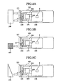
- the vehicle 100 causes an offset collision_with a barrier at a high velocity, e.g. a collision with an aluminum barrier (honeycomb structural wall made with aluminum) 107 at 64 kilometer/hour having a 40% striking area of the vehicle 100's surface, as shown in Fig. 3A, the front surface anterior to the left side seat of the vehicle 100 strikes the aluminum barrier 107.
- a barrier at a high velocity e.g. a collision with an aluminum barrier (honeycomb structural wall made with aluminum) 107 at 64 kilometer/hour having a 40% striking area of the vehicle 100's surface
- the collision load applied to the vehicle 100 is transmitted to the vehicle occupant room 105 through limited routes such as only one of the side members 104, 104 fixed to the both sides of the engine 102, etc.
- an arrow designates a transmission route of the collision load.
- the damping amount of acceleration caused by the transmission from the first acceleration sensor 2 to the second acceleration sensor 8 (i.e. the difference 18a) becomes relatively great, and,_as indicated with the symbol B in Fig. 4, the difference 18a exceeds the second initiation threshold value TH2 by a lapse of 30 milliseconds from the time the collision occurred.
- the second initiation command 22a can be outputted from the second initiation determination device 23 within a short time like 30 milliseconds from the collision occurrence and therefore the airbag can be fully unfolded.
- the front surface anterior to the left side seat of the vehicle 100 strikes the barrier 106 because the barrier 106 is placed obliquely.
- the collision load applied to the vehicle 100 is transmitted to the vehicle occupant room 105 through limited routes such as only one of the side members 104, 104 fixed to the both sides of the engine 102, etc.
- an arrow designates a transmission route of the collision load.
- the damping amount of acceleration caused by the transmission from the first acceleration sensor 2 to the second acceleration sensor 3 (i.e. the difference 18a) becomes relatively great, and,_as indicated with the symbol C in Fig. 4, the difference 18a exceeds the second initiation threshold value TH2 by a lapse of 30 milliseconds from the time the collision occurred.
- the second initiation command 22a can be outputted from the second initiation determination device 23 within a short time like 30 milliseconds from the collision occurrence and therefore the airbag can be fully unfolded.
- the second inflator 62 can be initiated at proper timing in response to a type of an occurring vehicle collision, and thus the airbag can be fully unfolded at proper timing.
- a first acceleration integrated value 16a is obtained by taking the time integral of acceleration in the vehicle 100's longitudinal direction detected with the first acceleration sensor 2 attached to the anterior portion of the vehicle 100
- a second acceleration integrated value 17a is obtained by taking the time integral of acceleration in the vehicle 100's longitudinal direction detected with the second acceleration sensor 3 attached to the substantially central portion of the vehicle 100
- the airbag (not shown) is unfolded after judging a collision type using the difference between the first acceleration integrated value 16a and the second acceleration integrated value 17a.
- a collision type can be properly judged by using a damping amount of acceleration which indicates how much amount of acceleration is reduced within transmission of a collision impact between the first acceleration sensor 2 and the second acceleration sensor 3.
- the airbag can be half unfolded or fully unfolded according to a type of collision.
- the vehicle occupant protection apparatus 1 is provided with the first acceleration sensor 2, attached to the front portion of the vehicle 10, for detecting acceleration in the vehicle 10's longitudinal direction; the second acceleration sensor 3, attached anterior to the position to which the first sensor 2 is attached in the vehicle 10's longitudinal direction, for detecting acceleration in the vehicle 10's longitudinal direction; the integral initiation control device 16 for issuing an integral initiation command at the time acceleration detected by the first acceleration sensor 2 exceeds the preset threshold value for determining whether collision of the vehicle 10 is occurring; the first acceleration integral device 16 for obtaining a first integral acceleration value by taking the time integral of output from the first acceleration sensor 2 based on the integral initiation command; the second acceleration integral device 17 for obtaining a second integral acceleration value by taking the time integral of output from the second acceleration sensor 3 based on the integral initiation command; the subtraction device 18 for subtracting the second integral acceleration value from the first integral acceleration value to obtain a difference thereof; the initiation determination device 20 for comparing the difference to the first threshold value and to the second threshold value, both
- the first and second embodiments employ the airbag apparatus as a vehicle occupant protection device.
- the vehicle occupant protection apparatus in accordance with the present invention can be applicable to control over a vehicle occupant protection device (e.g. a seat belt pretensioner device) desired to be variously operated in accordance with a collision type.
- a vehicle occupant protection device e.g. a seat belt pretensioner device
- this invention has been particularly shown and described with references to preferred embodiments thereof, it will be understood by those skilled in the art that various changes in form and details may be made therein without departing from the spirit and scope of the invention as defined by the appended claims.
Landscapes
- Engineering & Computer Science (AREA)
- Mechanical Engineering (AREA)
- Air Bags (AREA)
Abstract
Description
- The present invention relates to a vehicle occupant protection apparatus for protecting a vehicle occupant by controlling an operation of an occupant protection device (e.g. an airbag apparatus) according to a type of collision while a vehicle is colliding, and an initiation method to use for the vehicle occupant protection apparatus.
- Conventionally, there is known a vehicle occupant protection apparatus for determining greatness of collision velocity by using a change in acceleration with time (a time-integrated value of acceleration and a time-differentiated value of acceleration) detected by a single acceleration sensor (for reference, see Japanese Patent Laid-Open No. H10-29494).
- In the above apparatus, each of two inflators is not driven when the collision velocity is notably small, and only a first inflator is driven to half unfold an airbag (to inflate an airbag with a low pressure) when the collision velocity is medium, and further, after the first inflator is driven a second inflator is driven to fully unfold the airbag (to inflate the airbag with a high pressure) when the collision velocity is great.
- Also, there is known a vehicle occupant protection apparatus which detects deceleration with a single acceleration sensor, then calculates a first integrated value which is a time integrated value of the deceleration, then calculates a second integrated value by taking the time-integral of the first integrated value, then adds a weight value to each of the first integrated value and the second integrated value, and then drives an airbag by estimating movement of a vehicle occupant using the calculated sum (for reference, see Japanese Patent Publication No. H08-25430)
- It is proposed that a vehicle occupant protection apparatus detects acceleration with a single acceleration sensor thereof, then calculates acceleration, greatness of the acceleration, change in acceleration with time and a reduced quantity of velocity with a control circuit thereof, then estimates a scale of an impact by using those calculated values, and then drives each inflator according to the estimated scale (for reference, see Japanese Patent Laid-Open No. 2004-131084).
- It is also proposed that an initiation control apparatus for use on a vehicle occupant protection apparatus detects deceleration of a vehicle with a single acceleration sensor thereof, then calculates a integral velocity value, which is a time integrated value of the deceleration, then detects when the integral velocity value exceeds a first predetermined threshold value and initiates a first inflator, and then initiates a second inflator at the time the integral velocity exceeds a second predetermined threshold value, so that the second inflator can be driven without fault in the case the time integrated value of the deceleration delays in responding after the first inflator is driven in an offset collision, by improving arithmetic calculation process (for reference, see Japanese Patent Laid-Open No. H11-263188).
- Normally, when protecting a vehicle occupant from a collision impact by way of unfolding an airbag, since the time for inflating an airbag should be considered, a type of the collision needs to be determined until 30 milliseconds (0.03 seconds) before the impact of the collision which may damage the occupant applies to the occupant to inflate the airbag according to the type of the collision.
- That is, as described in H11-263188, there is a case where an airbag is fully unfolded (is inflated with a high pressure), and there is another case where the airbag is half unfolded (is inflated with a low preseure), according to the type of a collision.
- However, in the vehicle occupant protection apparatus described in H11-263188, if the first and second threshold values are predetermined in order to drive the first inflator when a low velocity head-on collision occurred and to drive the first and second inflator when a high velocity head-on collision occurred, then there may rise a case where the integrated value of the acceleration exceeds the first threshold value but does not exceed the second threshold value when a high velocity oblique collision or a high velocity offset collision occurs, and in such a case the second inflator may not be driven.
- Fig. 5 is a graph showing the problem described above. The lateral axis designates elapsed time from the beginning of a collision occurs, and the vertical axis designates integrated values of acceleration (time integrated values from the time collision occurs) detected with an acceleration sensor. The acceleration sensor may be attached either to an anterior-end portion of a vehicle or to a substantially central portion of the vehicle. In the graph "th1" designates a threshold value for initiating the first inflator and "th2" designates a threshold value for initiating the second inflator. The symbol "a" designates a characteristic of change in the integrated value in the case where a head-on collision occurs at a low velocity (e.g. 26 kilometer/hour). The symbol "b" designates a characteristic of change in the integrated value in the case where a head-on collision occurs at a high velocity (e.g. 35 kilometer/hour). The symbol "c" designates a characteristic of change in the integrated value in the case where an onset/oblique collision occurs at a high velocity (e.g. an offset collision at 64 kilometer/hour or an oblique collision at 40 kilometer/hour). As indicated with the symbol "c", in a high velocity offset collision or a high velocity oblique collision there might occur the case where the integrated value of the acceleration exceeds the first threshold value th1 but does not exceed the second threshold value th2, and in such a case the second inflator may not be driven. Further, in the case where a high velocity offset collision or a high velocity oblique collision occurs, it might take time for the integrated value of acceleration to reach the second threshold value, thus the timing for initiating the second inflator might not be proper. Further to this, another vehicle occupant protection apparatus is described in Japanese Patent Laid·Open No. 2001-10441.
- Thus, an object of the present invention is to provide a vehicle occupant protection apparatus and an initiation method to use for the vehicle occupant protection apparatus capable of more properly initiating a vehicle occupant protection device according to a collision type by determining the collision type when a vehicle collides.
- According to one aspect of the present invention, a vehicle occupant protection apparatus comprisises: a first acceleration sensor, attached to a front portion of a vehicle, for detecting acceleration in the vehicle's longitudinal direction; a second acceleration sensor, attached to a substantially central portion in the vehicle's longitudinal direction, for detecting acceleration in the vehicle's longitudinal direction; an integral initiation control device for issuing an integral initiation command at the time acceleration detected by the first acceleration sensor exceeds a preset threshold value for determining whether a collision of the vehicle is occurring; a first acceleration integral device for obtaining a first integral acceleration value by taking the time integral of acceleration detected by the first acceleration sensor based on the integral initiation command from the integral initiation control device; a second acceleration integral device for obtaining a second integral acceleration value by taking the time integral of acceleration detected by the second acceleration sensor based on the integral initiation command from the integral initiation control device; a subtraction device for calculating a difference between the first integral acceleration value and the second integral acceleration value; and an initiation determining device for determining a type of the collision using the deference calculated by the subtraction device and starting an operation of a vehicle protection device a protecting a vehicle occupant of the vehicle based on the determined type of the collision.
- The present application claims the benefit of priority to Japan Patent Application Nos. JP2004-227434, filed on August 4, 2004 and 2004-204078, filed on July 12, 2004, which are hereby incorporated by reference.
- For a better understanding of the invention, reference is made to the attached drawings, wherein:
- Fig. 1 is a block diagram showing a vehicle occupant protection apparatus of embodiments according to the present invention.
- Fig. 2 is a graph for describing an operation of a vehicle occupant protection apparatus of a first embodiment according to the present invention.
- Fig. 3A is a schematic diagram exemplarily showing an experiment in a head-on collision of a vehicle.
- Fig. 3B is a schematic diagram exemplarily showing an experiment in an offset collision of a vehicle.
- Fig. 3C is a schematic diagram exemplarily showing an experiment in an oblique collision of a vehicle.
- Fig. 4 is a graph for describing an operation of a vehicle occupant protection apparatus of a second embodiment according to the present invention.
- Fig. 5 is a graph for describing a problem of a conventional vehicle occupant protection apparatus.
- Preferred embodiments of the present invention will be explained below by referring to the accompanying drawings.
- Fig. 1 is a block diagram showing a vehicle occupant protection apparatus of the first embodiment according to the present invention. The vehicle occupant protection apparatus 1 according to the present invention includes a first acceleration sensor (front acceleration sensor) 2, a second acceleration sensor (central acceleration sensor) 3, an airbag unfolding determining
structure 4 as an initiation determining structure, an airbagunfolding driving device 5 as a driving device, and anairbag apparatus 6 as a vehicle occupant protection device. - The
first acceleration sensor 2 is attached to a substantially center of a front portion (nearby a radiator grille, for example) of a vehicle. Thefirst acceleration sensor 2 detects acceleration of the vehicle in a longitudinal direction (vehicle's longitudinal acceleration) and outputs a detected acceleration output signal. - The
second acceleration sensor 3 is attached to a substantially center of the vehicle both in a longitudinal direction and in a lateral direction (e.g. a floor tunnel portion or a floor face close to a shift lever in the vehicle). Thissecond acceleration sensor 3 does not need be located in an exact center of the vehicle in the longitudinal direction, and may be located in a portion closer to the center in the vehicle's longitudinal direction than a portion to which thefirst acceleration sensor 2 is attached. Preferably, thesecond acceleration sensor 3 is attached to a portion located in a vehicle occupant area (i.e. an inside, an upside or a lower part of a vehicle occupant room). - In this embodiment, the
first acceleration sensor 2 and thesecond acceleration sensor 3 output a positive (+) value for indicating acceleration tending to slow down the vehicle (i.e. deceleration) and a negative (-) value for indicating acceleration tending to speed up the vehicle in the case where output voltage is set to zero (0) while no acceleration is applied thereto. - The airbag unfolding determining
structure 4 is provided with LPFs (law-pass filter) 11, 12, A/D converters initiation control device 15, a first accelerationintegral device 16, a second accelerationintegral device 17, asubtraction device 18, a firstinitiation determining device 21, a first initiation threshold value producing device 22, a secondinitiation determining device 23, and a second initiation thresholdvalue producing device 24. In this embodiment, the first and secondinitiation determining devices value producing devices 22, 24 constitute aninitiation determining device 20 as set forth in the claims. - With the
LPF 11, a high-frequency noise component is removed and a low-frequency component in response to a vehicle collision is abstracted from the detected acceleration output signal from thefirst acceleration sensor 2, and then the abstracted low-frequency component is provided for the A/D converter 13 to be converted into a digital signal. Further, a high pass filter (not shown) may be employed in a previous step of theLPF 11, so that an influence of drift current of output voltage from thefirst acceleration sensor 2 can be excluded. A front acceleration digital signal (front acceleration data) outputted from the A/D converter 13 is provided for the integralinitiation control device 15 and the first accelerationintegral device 16. - The integral
initiation control device 15 continuously monitors the front acceleration (acceleration of the anterior portion of the vehicle) based on the front acceleration digital signal (front acceleration data), and issues anintegral initiation command 15a at the time the front acceleration exceeds a preset collision determining threshold value (e.g. 2 to 4 G (about 19.6 to 39.2 m/sec2)). Also, the integralinitiation control device 15 issues areset command 15b when the front acceleration remains under the preset collision determining threshold value (e.g. 2 to 4 G (about 19.6 to 39.2 m/sec2)) for a preset time (e.g. 100 millisecond). Theintegral initiation command 15a is provided for the first accelerationintegral device 16, the second accelerationintegral device 17, the first initiation threshold value producing device 22, and the second initiation thresholdvalue producing device 24, respectively. Thereset command 15b is provided for the first accelerationintegral device 16 and the second accelerationintegral device 17, respectively. - The first acceleration
integral device 16 starts time-integrating the front acceleration at the time theintegral initiation command 15a is provided, based on the front acceleration digital signal (front acceleration data). The first accelerationintegral device 16 continues taking the time integral of the front acceleration until thereset command 15b is provided therefor, and clears the integrated value to zero at the time thereset command 15b is provided therefor. The time integrated value of the acceleration of the front portion (first acceleration integrated value) is provided for thesubtraction device 18. - With the LPF 12 a high-frequency noise component is removed from and a low-frequency component in response to a vehicle collision is abstracted from the detected acceleration output signal outputted from the
second acceleration sensor 3, and then the abstracted low-frequency component is provided for the A/D converter 14 to be converted into a digital signal. Further, a high pass filter (not shown) may be employed in a previous step of theLPF 12, so that an influence of drift current of output voltage from thesecond acceleration sensor 3 can be excluded. A central acceleration digital signal (central acceleration data) is provided for the second accelerationintegral device 17. - The second acceleration
integral device 17 starts time-integrating of the central acceleration at the time theintegral initiation command 16a is provided therefor, based on the central acceleration digital signal (central acceleration data). The second accelerationintegral device 17 continues taking the time integral of the central acceleration until thereset command 15b is provided therefor, and clears the integrated value to zero at the time thereset command 15b is provided therefor. The time integrated value of the acceleration of the central portion (second acceleration integrated value) is provided for thesubtraction device 18. - The
subtraction device 18 subtracts the time integrated value of the acceleration of the central portion (second acceleration integrated value) from the time integrated value of the acceleration of the front portion (first acceleration integrated value) and outputs the difference of them. The difference outputted from thesubtraction device 18 is provided for the firstinitiation determining device 21 and the secondinitiation determining device 23, respectively. - The first initiation threshold value producing device 22 generates a first initiation threshold value TH1 predetermined in accordance with elapsed time from receipt of the
integral initiation command 15a. This first initiation threshold value TH1 is provided for the firstinitiation determining device 21. - The first
initiation determining device 21 compares the difference obtained by subtracting the time integrated value of the acceleration of the central portion (second acceleration integrated value) from the time integrated value of the acceleration of the front portion (first acceleration integrated value) with the first initiation threshold value TH1, and outputs a first initiation command at the time the difference exceeds the first initiation threshold value TH1. - The second initiation threshold
value producing device 24 generates a second initiation threshold value TH2 predetermined in accordance with elapsed time from receipt of theintegral initiation command 15a. This second initiation threshold value TH2 is provided for the secondinitiation determining device 23. - The second
initiation determining device 23 compares the difference obtained by subtracting the time integrated value of the acceleration of the central portion (second acceleration integrated value) from the time integrated value of the acceleration of the front portion (first acceleration integrated value) with the second initiation threshold value TH2, and outputs a second initiation command at the time the difference exceeds the second initiation threshold value TH2. - The first initiation threshold value TH1 is set in order that a low velocity collision can be detected thereby. The second initiation threshold value TH2 is greater than the first initiation threshold value TH1 and is set in order that a high velocity collision can be detected thereby.
- The
airbag apparatus 6 is a two-step type having thefirst inflator 61 and thesecond inflator 62, and is provided with each gas generating material (not shown) initiated by first andsecond squibs - The airbag unfolding driving
device 5 is provided with a first initiatingcircuit 51 for initiating thefirst squib 611 by applying currency, based on the first initiation command, and a second initiatingcircuit 52 for initiating thesecond squib 621 by applying currency, based on the second initiation command. - In this connection, when the difference does not exceed the second initiation threshold value TH2 for a predetermined time (e.g. 100 millisecond) from the time the first initiation command is outputted from the first
initiation determining device 21, the secondinitiation determining device 23 may be configured to output the second initiation command (forcible initiation command) at the time a predetermined time (e.g. 100 millisecond) elapses from the time the first initiation command is outputted. By so doing, unconsumed explosive does not remain after completion of an operation of theairbag apparatus 6. Further, the forcible initiation command may not be outputted from the secondinitiation determining device 23, instead, the second initiatingcircuit 52 may be configured to output the forcible initiation command. - Fig. 2 is a graph for describing an operation of a vehicle occupant protection apparatus of the first embodiment according to the present invention. The lateral axis designates elapsed time from when the
integral initiation command 15a is outputted from the integral initiation control device 15 (elapsed time from the time a collision occurred). The vertical axis designates the difference, which is an output from the subtraction device 18 (i.e. the first acceleration integrated value minus (-) the second first acceleration integrated value). A symbol "TH1" designates the first initiation threshold value produced by the first initiation threshold value producing device 22, a symbol "TH2" designates the second initiation threshold value produced by the second initiation thresholdvalue producing device 24. - A symbol "A" designates a characteristic of change in the difference in the case where a head-on collision occurs at a low velocity (e.g. a head-on collision (full-wrap collision) at 26 kilometer/hour). In a low velocity head-on collision, the difference exceeds the first initiation threshold TH1 at the point "ta", and at this point the first initiation command is outputted from the first
initiation determining device 21 to thefirst squib 611 via the first initiatingcircuit 51, initiating thefirst squib 611, thereby the first inflator is initiated and the airbag is half unfolded (is inflated with a low pressure). Since the difference in a low velocity head-on collision does not exceed the second initiation threshold value TH2, the second initiation command responsive to the second initiation threshold value TH2 is not produced. Alternatively, the forcible initiation command is produced at the time the predetermined time (e.g. 100 millisecond) elapses from the time the first initiation command is outputted, initiating thesecond inflator 62 to fully unfold the airbag (to inflate the airbag with a high pressure). - The symbol "B" designates a characteristic of change in the difference in a high velocity head-on collision (e.g. a head-on collision (full-wrap collision) at 35 kilometer/hour). In a high velocity head-on collision, the difference exceeds the first initiation threshold TH1 at the point "tb", and at this point the first initiation command is outputted from the first
initiation determining device 21, then the airbag is half unfolded (is inflated with a low pressure). Further, the difference exceeds the second initiation threshold TH2 at the point "tc", and at this point the second initiation command is outputted from the secondinitiation determining device 23 to thesecond squib 621 via the second initiatingcircuit 52, thesecond squib 621 is initiated, thesecond inflator 62 is initiated, and the airbag is fully unfolded (is inflated with a high pressure). - The symbol "C' designates a characteristic of change in the difference in a high velocity offset collision (e.g. an offset collision at 64 kilometer/hour) or a high velocity oblique collision (e.g. an oblique collision at 40 kilometer/hour). In a high velocity offset collision or a high velocity oblique collision the difference exceeds the first initiation threshold TH1 at the point "td", and at this point the first initiation command is outputted from the first
initiation determining device 21, then the airbag is half unfolded (is inflated with a low pressure). Further, the difference exceeds the second initiation threshold TH2 at the point "te", and at this point the second initiation command is outputted from the secondinitiation determining device 23, and the airbag is fully unfolded (is inflated with a high pressure). - Thus, by comparing the difference (i.e. the first acceleration integrated value minus (-) the second first acceleration integrated value) with each initiation threshold value TH1, TH2, it is surely determined which collision is occurring, a low velocity head-on collision, which produces relatively low impact, where the
second inflator 62 is not necessarily initiated, or a high velocity collision, which produces relatively high impact, where thesecond inflator 62 need be initiated, and moreover, thesecond inflator 62 can be initiated at proper timing in response to a degree of impact to half-unfold the airbag (to inflate the airbag with a high pressure). - As described above, the vehicle occupant protection apparatus 1 according to the present invention includes: the
first acceleration sensor 2, attached to the front portion of the vehicle 10, for detecting acceleration in the vehicle 10's longitudinal direction; thesecond acceleration sensor 3, attached to the substantially central portion in the vehicle 10's longitudinal direction, for detecting acceleration in the vehicle 10's longitudinal direction;
the integralinitiation control device 15 for issuing an integral initiation command at the time acceleration detected by thefirst acceleration sensor 2 exceeds the preset threshold value for determining whether a collision of the vehicle 10 is occurring; the first accelerationintegral device 16 for obtaining a first integral acceleration value by taking the time integral of acceleration detected by thefirst acceleration sensor 2 based on the integral initiation command from the integralinitiation control device 15; the second accelerationintegral device 17 for obtaining a second integral acceleration value by taking the time integral of acceleration detected by thesecond acceleration sensor 3 based on the integral initiation command from the integralinitiation control device 15; thesubtraction device 18 for calculating a difference between the first integral acceleration value and the second integral acceleration value; and theinitiation determining device 20 for determining a type of the collision using the deference calculated by thesubtraction device 18 and starting an operation of the airbag apparatus (vehicle protection device) 6 for protecting a vehicle occupant of the vehicle 10 based on the determined type of the collision. - The vehicle occupant protection apparatus 1 obtains a difference by subtracting a second acceleration integrated value obtained by taking the time integral of an output from the
second acceleration sensor 3 from a first acceleration integrated value obtained by taking the time integral of an output from thefirst acceleration sensor 2 located in an anterior portion of the vehicle 10, and judges initiation of the first andsecond inflators second inflator 62 can be surely initiated at proper timing not only in a high velocity head-on collision but also in a high velocity offset/oblique collision. - The second embodiment according to the present invention is, like the first embodiment, shown in the block diagram of Fig. 1. The vehicle occupant protection apparatus 1 according to the present invention is provided with a first acceleration sensor (front acceleration sensor) 2, a second acceleration sensor (central acceleration sensor) 3, an airbag unfolding determining
structure 4, anairbag driving device 5, and anairbag apparatus 6. - Further, as shown in Figs. 3A, 3B and 3C, a
bumper armature 101 extending in avehicle 100's lateral direction is located in an anterior portion of thevehicle 100, and aradiator 103 for cooling anengine 102 is located in the back of thebumper armature 101. - A couple of
side members engine 102, extending in a longitudinal direction of thevehicle 100. Front ends of theside members bumper armature 101, and back ends of theside members vehicle occupant room 105. - The
first acceleration sensor 2 is attached to a radiator core (not shown) which supports theradiator 103, and thesecond acceleration sensor 3 is located in a substantially central portion of thevehicle occupant room 105. - That is, in this embodiment, the
first acceleration sensor 2 is attached to an anterior portion located in a substantially center in thevehicle 100's lateral direction. Thefirst acceleration sensor 2 detects acceleration in thevehicle 100's longitudinal direction and outputs a detected front acceleration output signal. - The
second acceleration sensor 3 is attached to a substantially center in thevehicle 100's longitudinal and lateral direction (e.g. a floor tunnel portion or a floor face close to a shift lever in the vehicle). Thesecond acceleration sensor 3 detects acceleration in thevehicle 100's longitudinal direction and outputs a detected central acceleration output signal. - In this connection, the
second acceleration sensor 3 does not have to be located in the exactly center in thevehicle 100's longitudinal direction, and may be located at least posterior to thefirst acceleration sensor 2. - The
first acceleration sensor 2 and thesecond acceleration sensor 3 output a positive (+) value for indicating acceleration tending to slow down the vehicle 100 (i.e. deceleration) and a negative (-) value for indicating acceleration tending to speed up thevehicle 100 in the case where output voltage is set to zero (0) while no acceleration is applied thereto. - The airbag unfolding determining
structure 4 is provided with a front LPF (law-pass filter) 11, acentral LPF 12, afront AID converter 13, a central A/D converter 14, an integralinitiation control device 15, a first accelerationintegral device 16, a second accelerationintegral device 17, asubtraction device 18, a collision-type determining device 20 as an initiation determining device. - The
front LPF 11 and thecentral LPF 12 remove a high-frequency noise component and abstract a low-frequency component in response to a vehicle collision, from the detected acceleration output signal inputted from thefirst acceleration sensor 2 and thesecond acceleration sensor 3 respectively. - A high pass filter (not shown) may be employed in a previous step of the
front LPF 11, so that an influence of drift current of output voltage from thefirst acceleration sensor 2 can be excluded. Also, a high pass filter (not shown) may be employed in a previous step of thecentral LPF 12, so that an influence of drift current of output voltage from thefirst acceleration sensor 3 can be excluded. - The front A/
D converter 13 and the central A/D converter 14 convert a low-frequency component according to a vehicle collision inputted via thefront LPF 11 or thecentral LPF 12 into digital data. - A front acceleration digital signal (front acceleration data) outputted from the front A/
D converter 13 is provided for the integralinitiation control device 15 and the first accelerationintegral device 16. A central acceleration digital signal (central acceleration data) outputted from the central A/D converter 14 is provided for the second accelerationintegral device 17. - The integral
initiation control device 15 continuously monitors the front acceleration (acceleration of the anterior portion of the vehicle 100) based on the front acceleration digital signal (front acceleration data), and issues anintegral initiation command 15a at the time the front acceleration exceeds a preset collision determining threshold value (e.g. 2 to 4 G (about 19.6 to 39.2 m/sec2)). - Moreover, the integral
initiation control device 15 issues areset command 15b when the front acceleration remains below the preset collision determining threshold value (e.g. 2 to 4 G (about 19.6 to 39.2 m/sec2)) for a preset time (e.g. 100 millisecond). - The
integral initiation command 15a is provided for the first accelerationintegral device 16, the second accelerationintegral device 17, a first initiation threshold value producing device 22 (which will be described later), and a second initiation threshold value producing device 24 (which will be described later), respectively. Thereset command 15b is provided for the first accelerationintegral device 16 and the second accelerationintegral device 17, respectively. - The first acceleration
integral device 16 starts time-integrating the front acceleration based on the front acceleration digital signal (front acceleration data) at the time theintegral initiation command 15a is provided therefor. The first accelerationintegral device 16 continues taking the time integral of the front acceleration until thereset command 15b is provided therefor, and clears the integrated value to zero at the time thereset command 15b is provided therefor. The time integrated value of the acceleration of the front portion (first acceleration integrated value) 16a is provided for thesubtraction device 18. - The second acceleration
integral device 17 starts time-integrating of the central acceleration at the time theintegral initiation command 15a is provided therefor, based on the central acceleration digital signal (central acceleration data). The second accelerationintegral device 17 continues taking the time integral of the central acceleration until the reset command 16b is provided therefor, and clears the integrated value to zero at the time thereset command 15b is provided therefor. The time integrated value of the acceleration of the central portion (second acceleration integratedvalue 17a) is provided for thesubtraction device 18. - The
subtraction device 18 obtains adifference 18a by subtracting the time integrated value of the acceleration of the central portion (second acceleration integratedvalue 17a) from the time integrated value of the acceleration of the front portion (first acceleration integratedvalue 16a) and outputs thedifference 18a (=16a-17a). By so doing, a damping amount of acceleration, which represents how much amount of acceleration is reduced within transmission of a collision impact between thefirst acceleration sensor 2 and thesecond acceleration sensor 3 can be obtained. - The
difference 18a outputted from thesubtraction device 18 is provided for a firstinitiation determining device 21 and a secondinitiation determining device 23 of theinitiation determining device 20, respectively. - The
initiation determining device 20 includes the firstinitiation determining device 21, the first initiation threshold value producing device 22, the secondinitiation determining device 23 and the second initiation thresholdvalue producing device 24. Theinitiation determining device 20 determines a type of a vehicular collision by using the difference provided by thesubtraction device 18. - The first initiation threshold value producing device 22 generates a first initiation threshold value TH1 predetermined in accordance with elapsed time from receipt of an
integral initiation command 15a. This first initiation threshold value TH1 is provided for the firstinitiation determining device 21. - The first
initiation determining device 21 compares thedifference 18a obtained by subtracting the time integrated value of the acceleration of the central portion (second acceleration integratedvalue 17a) from the time integrated value of the acceleration of the front portion (first acceleration integratedvalue 16a) with the first initiation threshold value TH1, and outputs afirst initiation command 21a at the time thedifference 18a exceeds the first initiation threshold value TH1. - The second initiation threshold
value producing device 24 generates a second initiation threshold value TH2 predetermined in accordance with elapsed time from receipt of theintegral initiation command 16a. This second initiation threshold value TH2 is provided for the secondinitiation determining device 23. - The second
initiation determining device 23 compares thedifference 18a obtained by subtracting the time integrated value of the acceleration of the central portion (second acceleration integratedvalue 17a) from the time integrated value of the acceleration of the front portion (first acceleration integratedvalue 16a) with the second initiation threshold value TH2, and outputs asecond initiation command 22a at the time thedifference 18a exceeds the second initiation threshold value TH2. - The first initiation threshold value TH1 is set in order that a low velocity collision can be detected thereby. The second initiation threshold value TH2 is greater than the first initiation threshold value TH1 and is set in order that a high velocity collision can be detected thereby.
- The
airbag apparatus 6 is a two-step type having thefirst inflator 61 and thesecond inflator 62, and is provided with each gas generating material (not shown) initiated by afirst squib 611/second squib 621, a bag (not shown) inflated with the generated gas, and so forth. - The airbag unfolding driving
device 5 is provided with a first initiatingcircuit 51 for initiating thefirst squib 611 by applying currency, based on thefirst initiation command 21a, and a second initiatingcircuit 52 for initiating thesecond squib 621 by applying currency, based on thesecond initiation command 22a. - In this connection, when the
difference 18a does not exceed the second initiation threshold value TH2 for a predetermined time (e.g. 100 millisecond) from the time the first initiation command is outputted from the firstinitiation determining device 21, the secondinitiation determining device 23 may be configured to output the second initiation command (forcible initiation command) at the time a predetermined time (e.g. 100 millisecond) elapses from the time the first initiation command is outputted. - By so doing, unconsumed explosive does not remain after completion of an operation of the
airbag apparatus 6. The forcible initiation command may not be outputted from the secondinitiation determining device 23, instead, the second initiatingcircuit 52 may be configured to output the forcible initiation command. - The function of the vehicle occupant protection apparatus 1 according to the present invention will be described below.
- In the case where the
vehicle 100 as described above collides head-on with a barrier (a rigid concrete wall) 106 at a low velocity, e.g. 26 kilometer/hour, as shown in Fig. 3A, almost all area of the front surface of thevehicle 100strikes barrier 106 vertically. - In this case, since the collision area on the
vehicle 100 is large, the collision load applied to thevehicle 100 is transmitted to thevehicle occupant room 105 through various routes including bothside members engine 102, etc. In the Fig. 3A an arrow designates a transmission route of the collision load. - Thus, the damping amount of acceleration caused by the transmission from the
first acceleration sensor 2 to the second acceleration sensor 3 (i.e. thedifference 18a) becomes relatively small, and,_as indicated with the symbol A in Fig. 4, thedifference 18a does not exceed the second initiation threshold value TH2 from the time the collision occurred until a lapse of 30 milliseconds. - Thus, in the case where a head-on collision occurs at a low velocity, although produced acceleration in the beginning of the collision is great, the
second initiation command 22a is not outputted from the second initiation determination device and therefore the airbag can be half unfolded. - In the next case where the
vehicle 100 causes an offset collision_with a barrier at a high velocity, e.g. a collision with an aluminum barrier (honeycomb structural wall made with aluminum) 107 at 64 kilometer/hour having a 40% striking area of thevehicle 100's surface, as shown in Fig. 3A, the front surface anterior to the left side seat of thevehicle 100 strikes thealuminum barrier 107. - In this case, since the collision area on the
vehicle 100 is small, the collision load applied to thevehicle 100 is transmitted to thevehicle occupant room 105 through limited routes such as only one of theside members engine 102, etc. In the Fig. 3B an arrow designates a transmission route of the collision load. - Thus, the damping amount of acceleration caused by the transmission from the
first acceleration sensor 2 to the second acceleration sensor 8 (i.e. thedifference 18a) becomes relatively great, and,_as indicated with the symbol B in Fig. 4, thedifference 18a exceeds the second initiation threshold value TH2 by a lapse of 30 milliseconds from the time the collision occurred. - Thus, in the case where the
vehicle 100 causes an offset collision_at a high velocity, although produced acceleration in the beginning of the collision is small, thesecond initiation command 22a can be outputted from the secondinitiation determination device 23 within a short time like 30 milliseconds from the collision occurrence and therefore the airbag can be fully unfolded. - In the case where the
vehicle 100 collides obliquely with a barrier (a rigid wall made with concrete) 106 at a high velocity, e.g. 48 kilometer/hour, as shown in Fig. 3C, the front surface anterior to the left side seat of thevehicle 100 strikes thebarrier 106 because thebarrier 106 is placed obliquely. - In this case, since the collision area on the
vehicle 100 is small, the collision load applied to thevehicle 100 is transmitted to thevehicle occupant room 105 through limited routes such as only one of theside members engine 102, etc. In the Fig. 3C an arrow designates a transmission route of the collision load. - Thus, the damping amount of acceleration caused by the transmission from the
first acceleration sensor 2 to the second acceleration sensor 3 (i.e. thedifference 18a) becomes relatively great, and,_as indicated with the symbol C in Fig. 4, thedifference 18a exceeds the second initiation threshold value TH2 by a lapse of 30 milliseconds from the time the collision occurred. - Thus, in the case where the
vehicle 100 collides obliquely with abarrier 106 at a high velocity, although produced acceleration in the beginning of the collision is small, thesecond initiation command 22a can be outputted from the secondinitiation determination device 23 within a short time like 30 milliseconds from the collision occurrence and therefore the airbag can be fully unfolded. - Thus, by outputting the second initiation command based on a comparison result of the
difference 18a with the second initiation threshold value TH2, it can be surely determined which collision is occurring, a low velocity head-on collision which produces relatively low impact, where thesecond inflator 62 is not necessarily initiated or a high velocity offset/oblique collision which produces relatively high impact, where thesecond inflator 62 need be initiated. - Further, the
second inflator 62 can be initiated at proper timing in response to a type of an occurring vehicle collision, and thus the airbag can be fully unfolded at proper timing. - As described above, according to the unfolding judgment method for the vehicle occupant protection apparatus 1 of the present invention, a first acceleration integrated
value 16a is obtained by taking the time integral of acceleration in thevehicle 100's longitudinal direction detected with thefirst acceleration sensor 2 attached to the anterior portion of thevehicle 100, and a second acceleration integratedvalue 17a is obtained by taking the time integral of acceleration in thevehicle 100's longitudinal direction detected with thesecond acceleration sensor 3 attached to the substantially central portion of thevehicle 100, and then the airbag (not shown) is unfolded after judging a collision type using the difference between the first acceleration integratedvalue 16a and the second acceleration integratedvalue 17a. - By so doing, a collision type can be properly judged by using a damping amount of acceleration which indicates how much amount of acceleration is reduced within transmission of a collision impact between the
first acceleration sensor 2 and thesecond acceleration sensor 3. Thus, the airbag can be half unfolded or fully unfolded according to a type of collision. - The vehicle occupant protection apparatus 1 according to the second embodiment of the present invention is provided with the first acceleration sensor 2, attached to the front portion of the vehicle 10, for detecting acceleration in the vehicle 10's longitudinal direction; the second acceleration sensor 3, attached anterior to the position to which the first sensor 2 is attached in the vehicle 10's longitudinal direction, for detecting acceleration in the vehicle 10's longitudinal direction; the integral initiation control device 16 for issuing an integral initiation command at the time acceleration detected by the first acceleration sensor 2 exceeds the preset threshold value for determining whether collision of the vehicle 10 is occurring; the first acceleration integral device 16 for obtaining a first integral acceleration value by taking the time integral of output from the first acceleration sensor 2 based on the integral initiation command; the second acceleration integral device 17 for obtaining a second integral acceleration value by taking the time integral of output from the second acceleration sensor 3 based on the integral initiation command; the subtraction device 18 for subtracting the second integral acceleration value from the first integral acceleration value to obtain a difference thereof; the initiation determination device 20 for comparing the difference to the first threshold value and to the second threshold value, both of which are predetermined in accordance with lapsed time from start time of taking the time integral, to output a first command at the time the difference reaches the first threshold value and a second command at the time the difference reaches the second threshold value; and the airbag driving device 5 for initiating the first inflator 61 of the airbag apparatus 6 based on the first command and initiating the second inflator 62 of the airbag apparatus 6 based on the second command.
- The first and second embodiments employ the airbag apparatus as a vehicle occupant protection device. However, the vehicle occupant protection apparatus in accordance with the present invention can be applicable to control over a vehicle occupant protection device (e.g. a seat belt pretensioner device) desired to be variously operated in accordance with a collision type.
While this invention has been particularly shown and described with references to preferred embodiments thereof, it will be understood by those skilled in the art that various changes in form and details may be made therein without departing from the spirit and scope of the invention as defined by the appended claims.
Claims (11)
- A vehicle occupant protection apparatus (1) characterized by comprising:a first acceleration sensor (2), attached to a front portion of a vehicle (10, 100), for detecting acceleration in the vehicle (10, 100)'s longitudinal direction;a second acceleration sensor (3), attached to a substantially central portion in the vehicle (10, 100)'s longitudinal direction, for detecting acceleration in the vehicle (10, 100)'s longitudinal direction;an integral initiation control device (15) for issuing an integral initiation command at the time acceleration detected by the first acceleration sensor (2) exceeds a preset threshold value for determining whether a collision of the vehicle (10, 100) is occurring;a first acceleration integral device (16) for obtaining a first integral acceleration value by taking the time integral of acceleration detected by the first acceleration sensor (2) based on the integral initiation command from the integral initiation control device (15);a second acceleration integral device (17) for obtaining a second integral acceleration value by taking the time integral of acceleration detected by the second acceleration sensor (3) based on the integral initiation command from the integral initiation control device (15);a subtraction device (18) for calculating a difference between the first integral acceleration value and the second integral acceleration value; andan initiation determining device (20) for determining a type of the collision using the deference calculated by the subtraction device (18) and starting an operation of a vehicle protection device (6) for protecting a vehicle occupant of the vehicle (10, 100) based on the determined type of the collision.
- The vehicle occupant protection apparatus (1) according to claim 1, characterized in that the vehicle protection device (6) is an airbag apparatus.
- The vehicle occupant protection apparatus (1) according to claim 1, characterized in that the front portion of the vehicle (10, 100) to which the first acceleration sensor (2) is attached is located anterior to an occupant room of the vehicle.
- The vehicle occupant protection apparatus (1) according to claim 1, characterized in that the substantially central portion in the longitudinal direction of the vehicle (10, 100) to which the second acceleration sensor (3) is attached is located in an occupant room area of the vehicle (10, 100).
- The vehicle occupant protection apparatus (1) according to claim 1, characterized in that the first acceleration sensor (2) and/or the second acceleration sensor (3) is located in a substantially central portion in a lateral direction of the vehicle (10, 100).
- A vehicle occupant protection apparatus (1) characterized by comprising:a first acceleration sensor (2), attached to a front portion of a vehicle (10, 100), for detecting acceleration in the vehicle (10, 100)'s longitudinal direction;a second acceleration sensor (3), attached to a position which is closer to a center in the vehicle (10, 100)'s longitudinal direction than the front portion to which the first sensor (2) is attached, for detecting acceleration in the vehicle (10, 100)'s longitudinal direction;an integral initiation control device (15) for issuing an integral initiation command at the time acceleration detected by the first acceleration sensor (2) exceeds a preset threshold value for determining whether collision of the vehicle (10, 100) is occurring;a first acceleration integral device (16) for obtaining a first integral acceleration value by taking the time integral of output from the first acceleration sensor (2) based on the integral initiation command;a second acceleration integral device (17) for obtaining a second integral acceleration value by taking the time integral of output from the second acceleration sensor (3) based on the integral initiation command;a subtraction device (18) for subtracting the second integral acceleration value from the first integral acceleration value to obtain a difference thereof;an initiation determination device (20) for comparing the difference to a first threshold value and to a second threshold value, both of which are predetermined in accordance with lapsed time from start time of taking time integral, to output a first command at the time the difference reaches the first threshold value and a second command at the time the difference reaches the second threshold value; andan airbag driving device (5) for initiating a first inflator (61) of an airbag apparatus (6) based on the first command and initiating a second inflator (62) of the airbag apparatus (6) based on the second command.
- The vehicle occupant protection apparatus (1) according to claim 6, characterized in that the front portion of the vehicle to which the first acceleration sensor is attached is located anterior to an occupant room of the vehicle.
- The vehicle occupant protection apparatus according to claim 6, characterized in that the position to which the second sensor (3) is attached is located in an occupant room area of the vehicle (10, 100).
- The vehicle occupant protection apparatus according to claim 6, characterized in that the first acceleration sensor (2) and/or the second acceleration sensor (3) is located in a substantially center in a lateral direction of the vehicle (10, 100).
- A method for initiating a vehicle occupant protection apparatus (1) characterized by comprising the steps of:obtaining a first integral acceleration value by taking the time integral of acceleration in a longitudinal direction of a vehicle (10, 100) detected with a first acceleration sensor (2) attached to a front portion of the vehicle (10, 100);obtaining a second integral acceleration value by taking the time integral of acceleration in the longitudinal direction of the vehicle (10, 100) detected with a second acceleration sensor (3) attached to a portion closer to the vehicle (10, 100)'s center in the longitudinal direction than the front position to which the first acceleration sensor (2) is attached;determining a type of a collision of the vehicle (10, 100) by using the first integral acceleration value and the second integral acceleration value; andinitiating a vehicle occupant protection device (6) for protecting an occupant of the vehicle (10, 100) based on the determined type of the collision.
- The method for initiating a vehicle occupant protection apparatus (1) according to claim 6, characterized in that the vehicle occupant protection device (6) is an airbag apparatus.
Applications Claiming Priority (2)
| Application Number | Priority Date | Filing Date | Title |
|---|---|---|---|
| JP2004204078A JP4372631B2 (en) | 2004-07-12 | 2004-07-12 | Crew protection device |
| JP2004227434A JP4417200B2 (en) | 2004-08-04 | 2004-08-04 | Deployment determination method for occupant protection device and occupant protection device using the method |
Publications (2)
| Publication Number | Publication Date |
|---|---|
| EP1616758A1 true EP1616758A1 (en) | 2006-01-18 |
| EP1616758B1 EP1616758B1 (en) | 2007-12-26 |
Family
ID=35063329
Family Applications (1)
| Application Number | Title | Priority Date | Filing Date |
|---|---|---|---|
| EP05013367A Ceased EP1616758B1 (en) | 2004-07-12 | 2005-06-21 | Vehicle occupant protection apparatus and initiation method to use for vehicle occupant protection apparatus |
Country Status (3)
| Country | Link |
|---|---|
| US (1) | US7546193B2 (en) |
| EP (1) | EP1616758B1 (en) |
| DE (1) | DE602005003986T2 (en) |
Cited By (1)
| Publication number | Priority date | Publication date | Assignee | Title |
|---|---|---|---|---|
| EP3611060A4 (en) * | 2017-04-11 | 2021-01-20 | Veoneer Sweden AB | CONTROL DEVICE AND PROTECTION DEVICE CONTROL PROCESS |
Families Citing this family (8)
| Publication number | Priority date | Publication date | Assignee | Title |
|---|---|---|---|---|
| US9218465B2 (en) * | 2008-03-10 | 2015-12-22 | Jill Lewis Maurer | Digital media content creation and distribution methods |
| CN105128791B (en) | 2008-08-28 | 2017-09-01 | Trw汽车美国有限责任公司 | Method and apparatus for controlling activatable safety means |
| US8095275B2 (en) * | 2008-08-28 | 2012-01-10 | Trw Automotive U.S. Llc | Method and apparatus for controlling an actuatable safety device |
| JP5387892B2 (en) * | 2009-03-12 | 2014-01-15 | 株式会社ジェイテクト | Motor control device |
| DE102009054473A1 (en) * | 2009-12-10 | 2011-06-16 | Robert Bosch Gmbh | Method and control device for determining a type of collision of a vehicle |
| DE102011085565A1 (en) * | 2011-11-02 | 2013-05-02 | Robert Bosch Gmbh | Autonomous working device |
| JP5778236B2 (en) * | 2013-10-18 | 2015-09-16 | 本田技研工業株式会社 | Vehicle collision determination device |
| JP2024039286A (en) * | 2022-09-09 | 2024-03-22 | 株式会社Subaru | Collision type discrimination device |
Citations (8)
| Publication number | Priority date | Publication date | Assignee | Title |
|---|---|---|---|---|
| JPH0825430A (en) | 1994-07-12 | 1996-01-30 | Sanyo Electric Co Ltd | Ejector pin for injection molding machine |
| JPH1029494A (en) | 1996-05-14 | 1998-02-03 | Takata Kk | Air bag device |
| JPH11263188A (en) | 1998-03-19 | 1999-09-28 | Asuko Kk | Method and device for start control of occupant crash protection device and recording medium with start control program for occupant crash protection device recorded on it |
| EP0982199A1 (en) * | 1997-05-16 | 2000-03-01 | Autolive Japan Ltd. | Actuation controller for air bag device |
| JP2001010441A (en) | 1999-06-30 | 2001-01-16 | Calsonic Kansei Corp | Occupant crash protection |
| US20010043011A1 (en) * | 1999-03-02 | 2001-11-22 | Aki Ugusa | Crash detection apparatus of vehicle responsive to asymmetric collision |
| US6347268B1 (en) * | 1996-11-20 | 2002-02-12 | Toyota Jidosha Kabushiki Kaisha | Activation control apparatus for passive vehicle occupant restraint and method of controlling activation of passive vehicle occupant restraint |
| JP2004131084A (en) | 2004-02-05 | 2004-04-30 | Takata Corp | Occupant protection device |
Family Cites Families (21)
| Publication number | Priority date | Publication date | Assignee | Title |
|---|---|---|---|---|
| DE2745620A1 (en) * | 1977-10-11 | 1979-04-12 | Daimler Benz Ag | AIR BAG SYSTEM TO PROTECT THE OCCUPANTS OF A MOTOR VEHICLE IN THE EVENT OF ACCIDENTS |
| US5233530A (en) * | 1988-11-28 | 1993-08-03 | Mitsubishi Jidosha Kogyo Kabushiki Kaisha | Engine controlling system which reduces the engine output upon detection of an abnormal condition |
| US5276624A (en) * | 1990-01-25 | 1994-01-04 | Mitsubishi Jidosha Kogyo Kabushiki Kaisha | Turning control apparatus for vehicle |
| JPH0825430B2 (en) | 1990-08-24 | 1996-03-13 | 株式会社カンセイ | Vehicle occupant protection device |
| JPH04176752A (en) * | 1990-11-08 | 1992-06-24 | Matsushita Electric Ind Co Ltd | Collision detecting device |
| JPH04307348A (en) * | 1991-04-02 | 1992-10-29 | Toyota Motor Corp | Apparatus for detecting cornering power of wheel |
| US7481453B2 (en) * | 1991-07-09 | 2009-01-27 | Automotive Technologies International, Inc. | Inflator system |
| US5707077A (en) * | 1991-11-18 | 1998-01-13 | Hitachi, Ltd. | Airbag system using three-dimensional acceleration sensor |
| JP2562090B2 (en) * | 1991-12-16 | 1996-12-11 | スタンレー電気株式会社 | Rear impact warning device |
| JPH0796816A (en) * | 1993-09-30 | 1995-04-11 | Mitsubishi Motors Corp | Electronic airbag device |
| JP2941643B2 (en) * | 1994-04-14 | 1999-08-25 | 三菱自動車工業株式会社 | Starting device for occupant protection device |
| JPH09277901A (en) * | 1996-02-15 | 1997-10-28 | Toyota Motor Corp | Collision judgment value determination device and method thereof |
| US6189927B1 (en) * | 1999-12-16 | 2001-02-20 | Autoliv Asp, Inc. | Adaptive output inflator |
| US8251397B2 (en) * | 2000-10-20 | 2012-08-28 | Joseph Akwo Tabe | Advanced weight responsive supplemental restraint computer system |
| US6559557B2 (en) * | 2000-12-20 | 2003-05-06 | Delphi Technologies, Inc. | Error detection circuit for an airbag deployment control system |
| DE10134331C1 (en) * | 2001-07-14 | 2002-10-10 | Bosch Gmbh Robert | Controlling triggering of passive safety system involves detecting impact speed from time difference between start of impact, transition of acceleration from low to higher acceleration |
| GB2399137A (en) * | 2003-03-06 | 2004-09-08 | Autoliv Dev | Releasable safety clip |
| DE10361647A1 (en) * | 2003-12-30 | 2005-08-04 | General Motors Corp., Detroit | Vehicle safety system for use in a vehicle with a fuel cell system and an electric power source where the fuel cell system is connected to the air bag control |
| JP2004318902A (en) * | 2004-06-04 | 2004-11-11 | Nec Corp | Content delivery method and content delivery system |
| JP4896389B2 (en) * | 2004-11-02 | 2012-03-14 | カルソニックカンセイ株式会社 | Airbag deployment control device |
| US7505841B2 (en) * | 2005-09-02 | 2009-03-17 | Delphi Technologies, Inc. | Vision-based occupant classification method and system for controlling airbag deployment in a vehicle restraint system |
-
2005
- 2005-06-21 EP EP05013367A patent/EP1616758B1/en not_active Ceased
- 2005-06-21 DE DE602005003986T patent/DE602005003986T2/en not_active Expired - Lifetime
- 2005-06-22 US US11/158,341 patent/US7546193B2/en not_active Expired - Fee Related
Patent Citations (8)
| Publication number | Priority date | Publication date | Assignee | Title |
|---|---|---|---|---|
| JPH0825430A (en) | 1994-07-12 | 1996-01-30 | Sanyo Electric Co Ltd | Ejector pin for injection molding machine |
| JPH1029494A (en) | 1996-05-14 | 1998-02-03 | Takata Kk | Air bag device |
| US6347268B1 (en) * | 1996-11-20 | 2002-02-12 | Toyota Jidosha Kabushiki Kaisha | Activation control apparatus for passive vehicle occupant restraint and method of controlling activation of passive vehicle occupant restraint |
| EP0982199A1 (en) * | 1997-05-16 | 2000-03-01 | Autolive Japan Ltd. | Actuation controller for air bag device |
| JPH11263188A (en) | 1998-03-19 | 1999-09-28 | Asuko Kk | Method and device for start control of occupant crash protection device and recording medium with start control program for occupant crash protection device recorded on it |
| US20010043011A1 (en) * | 1999-03-02 | 2001-11-22 | Aki Ugusa | Crash detection apparatus of vehicle responsive to asymmetric collision |
| JP2001010441A (en) | 1999-06-30 | 2001-01-16 | Calsonic Kansei Corp | Occupant crash protection |
| JP2004131084A (en) | 2004-02-05 | 2004-04-30 | Takata Corp | Occupant protection device |
Cited By (2)
| Publication number | Priority date | Publication date | Assignee | Title |
|---|---|---|---|---|
| EP3611060A4 (en) * | 2017-04-11 | 2021-01-20 | Veoneer Sweden AB | CONTROL DEVICE AND PROTECTION DEVICE CONTROL PROCESS |
| US11554735B2 (en) | 2017-04-11 | 2023-01-17 | Arriver Software Ab | Control device, and method for controlling protective device |
Also Published As
| Publication number | Publication date |
|---|---|
| EP1616758B1 (en) | 2007-12-26 |
| DE602005003986T2 (en) | 2008-04-30 |
| US7546193B2 (en) | 2009-06-09 |
| US20060009895A1 (en) | 2006-01-12 |
| DE602005003986D1 (en) | 2008-02-07 |
Similar Documents
| Publication | Publication Date | Title |
|---|---|---|
| CN102407820B (en) | Collision determining apparatus for vehicle | |
| JP4063107B2 (en) | Occupant protection device starter | |
| JP3783925B2 (en) | Car occupant protection device | |
| JP3346472B2 (en) | Activation control device for occupant protection device | |
| KR102791259B1 (en) | Apparatus and method for controlling airbag | |
| US6756889B2 (en) | Dual sensor crash sensing system | |
| US7546193B2 (en) | Vehicle occupant protection apparatus and initiation method to use for vehicle occupant protection apparatus | |
| JP3632619B2 (en) | Occupant protection device starter | |
| JP3695351B2 (en) | Occupant protection device starter | |
| US7684914B2 (en) | Collision determining apparatus for a vehicle | |
| WO2006103810A1 (en) | Activation controller of occupant protection device | |
| CN112172724A (en) | How to inflate an airbag | |
| US7509196B2 (en) | Airbag development control apparatus | |
| JP2008514496A (en) | Drive control method for occupant protection means and drive control device for occupant protection means | |
| JP4417200B2 (en) | Deployment determination method for occupant protection device and occupant protection device using the method | |
| JP4306543B2 (en) | Activation control device for occupant protection device | |
| US7140464B2 (en) | Triggering unit | |
| JPH10315907A (en) | Expansion control device of air bag apparatus | |
| EP0931706A1 (en) | Device and method for protecting a vehicle occupant | |
| JP4372631B2 (en) | Crew protection device | |
| JP2004009804A (en) | Startup determination device for vehicle occupant protection device | |
| KR100636639B1 (en) | How to control the de-air airbag | |
| JP2001277999A (en) | Vehicle collision determination device | |
| JP5162415B2 (en) | Inclination detection device and occupant protection system | |
| JPH0585298A (en) | Operation control device for passenger protection device |
Legal Events
| Date | Code | Title | Description |
|---|---|---|---|
| PUAI | Public reference made under article 153(3) epc to a published international application that has entered the european phase |
Free format text: ORIGINAL CODE: 0009012 |
|
| AK | Designated contracting states |
Kind code of ref document: A1 Designated state(s): AT BE BG CH CY CZ DE DK EE ES FI FR GB GR HU IE IS IT LI LT LU MC NL PL PT RO SE SI SK TR |
|
| AX | Request for extension of the european patent |
Extension state: AL BA HR LV MK YU |
|
| 17P | Request for examination filed |
Effective date: 20060328 |
|
| AKX | Designation fees paid |
Designated state(s): DE FR GB |
|
| RIC1 | Information provided on ipc code assigned before grant |
Ipc: B60R 21/0132 20060101AFI20070307BHEP |
|
| GRAP | Despatch of communication of intention to grant a patent |
Free format text: ORIGINAL CODE: EPIDOSNIGR1 |
|
| GRAS | Grant fee paid |
Free format text: ORIGINAL CODE: EPIDOSNIGR3 |
|
| GRAA | (expected) grant |
Free format text: ORIGINAL CODE: 0009210 |
|
| AK | Designated contracting states |
Kind code of ref document: B1 Designated state(s): DE FR GB |
|
| REG | Reference to a national code |
Ref country code: GB Ref legal event code: FG4D |
|
| REF | Corresponds to: |
Ref document number: 602005003986 Country of ref document: DE Date of ref document: 20080207 Kind code of ref document: P |
|
| ET | Fr: translation filed | ||
| PLBE | No opposition filed within time limit |
Free format text: ORIGINAL CODE: 0009261 |
|
| STAA | Information on the status of an ep patent application or granted ep patent |
Free format text: STATUS: NO OPPOSITION FILED WITHIN TIME LIMIT |
|
| 26N | No opposition filed |
Effective date: 20080929 |
|
| REG | Reference to a national code |
Ref country code: FR Ref legal event code: PLFP Year of fee payment: 12 |
|
| REG | Reference to a national code |
Ref country code: FR Ref legal event code: PLFP Year of fee payment: 13 |
|
| REG | Reference to a national code |
Ref country code: FR Ref legal event code: PLFP Year of fee payment: 14 |
|
| PGFP | Annual fee paid to national office [announced via postgrant information from national office to epo] |
Ref country code: DE Payment date: 20180605 Year of fee payment: 14 |
|
| PGFP | Annual fee paid to national office [announced via postgrant information from national office to epo] |
Ref country code: FR Payment date: 20180511 Year of fee payment: 14 |
|
| PGFP | Annual fee paid to national office [announced via postgrant information from national office to epo] |
Ref country code: GB Payment date: 20180620 Year of fee payment: 14 |
|
| REG | Reference to a national code |
Ref country code: DE Ref legal event code: R119 Ref document number: 602005003986 Country of ref document: DE |
|
| GBPC | Gb: european patent ceased through non-payment of renewal fee |
Effective date: 20190621 |
|
| PG25 | Lapsed in a contracting state [announced via postgrant information from national office to epo] |
Ref country code: DE Free format text: LAPSE BECAUSE OF NON-PAYMENT OF DUE FEES Effective date: 20200101 Ref country code: GB Free format text: LAPSE BECAUSE OF NON-PAYMENT OF DUE FEES Effective date: 20190621 |
|
| PG25 | Lapsed in a contracting state [announced via postgrant information from national office to epo] |
Ref country code: FR Free format text: LAPSE BECAUSE OF NON-PAYMENT OF DUE FEES Effective date: 20190630 |